EP1343113A2 - Eingabegerät für in einem Fahrzeug eingebaute Instrumente - Google Patents
Eingabegerät für in einem Fahrzeug eingebaute Instrumente Download PDFInfo
- Publication number
- EP1343113A2 EP1343113A2 EP03004961A EP03004961A EP1343113A2 EP 1343113 A2 EP1343113 A2 EP 1343113A2 EP 03004961 A EP03004961 A EP 03004961A EP 03004961 A EP03004961 A EP 03004961A EP 1343113 A2 EP1343113 A2 EP 1343113A2
- Authority
- EP
- European Patent Office
- Prior art keywords
- switch
- driver
- input unit
- screen
- display
- Prior art date
- Legal status (The legal status is an assumption and is not a legal conclusion. Google has not performed a legal analysis and makes no representation as to the accuracy of the status listed.)
- Granted
Links
- 230000002093 peripheral effect Effects 0.000 claims description 6
- 210000003811 finger Anatomy 0.000 description 9
- XDLMVUHYZWKMMD-UHFFFAOYSA-N 3-trimethoxysilylpropyl 2-methylprop-2-enoate Chemical compound CO[Si](OC)(OC)CCCOC(=O)C(C)=C XDLMVUHYZWKMMD-UHFFFAOYSA-N 0.000 description 6
- 238000012423 maintenance Methods 0.000 description 6
- 101001057322 Synechocystis sp. (strain PCC 6803 / Kazusa) Methionine aminopeptidase C Proteins 0.000 description 5
- 238000007664 blowing Methods 0.000 description 5
- 238000001514 detection method Methods 0.000 description 5
- 238000000034 method Methods 0.000 description 5
- 230000008859 change Effects 0.000 description 4
- 238000003780 insertion Methods 0.000 description 3
- 230000037431 insertion Effects 0.000 description 3
- 238000009434 installation Methods 0.000 description 3
- 210000003813 thumb Anatomy 0.000 description 3
- 230000007704 transition Effects 0.000 description 3
- 238000013461 design Methods 0.000 description 2
- 210000005224 forefinger Anatomy 0.000 description 2
- 238000012986 modification Methods 0.000 description 2
- 230000004048 modification Effects 0.000 description 2
- 239000007787 solid Substances 0.000 description 2
- 101000911772 Homo sapiens Hsc70-interacting protein Proteins 0.000 description 1
- 101001139126 Homo sapiens Krueppel-like factor 6 Proteins 0.000 description 1
- 101000661807 Homo sapiens Suppressor of tumorigenicity 14 protein Proteins 0.000 description 1
- 244000060701 Kaempferia pandurata Species 0.000 description 1
- 235000016390 Uvaria chamae Nutrition 0.000 description 1
- 239000003086 colorant Substances 0.000 description 1
- 239000012141 concentrate Substances 0.000 description 1
- 230000000694 effects Effects 0.000 description 1
- 230000004044 response Effects 0.000 description 1
- 238000000638 solvent extraction Methods 0.000 description 1
- 210000000707 wrist Anatomy 0.000 description 1
Images


Classifications
-
- G—PHYSICS
- G06—COMPUTING; CALCULATING OR COUNTING
- G06F—ELECTRIC DIGITAL DATA PROCESSING
- G06F3/00—Input arrangements for transferring data to be processed into a form capable of being handled by the computer; Output arrangements for transferring data from processing unit to output unit, e.g. interface arrangements
- G06F3/01—Input arrangements or combined input and output arrangements for interaction between user and computer
- G06F3/048—Interaction techniques based on graphical user interfaces [GUI]
- G06F3/0484—Interaction techniques based on graphical user interfaces [GUI] for the control of specific functions or operations, e.g. selecting or manipulating an object, an image or a displayed text element, setting a parameter value or selecting a range
- G06F3/04842—Selection of displayed objects or displayed text elements
-
- B—PERFORMING OPERATIONS; TRANSPORTING
- B60—VEHICLES IN GENERAL
- B60R—VEHICLES, VEHICLE FITTINGS, OR VEHICLE PARTS, NOT OTHERWISE PROVIDED FOR
- B60R11/00—Arrangements for holding or mounting articles, not otherwise provided for
- B60R11/02—Arrangements for holding or mounting articles, not otherwise provided for for radio sets, television sets, telephones, or the like; Arrangement of controls thereof
- B60R11/0229—Arrangements for holding or mounting articles, not otherwise provided for for radio sets, television sets, telephones, or the like; Arrangement of controls thereof for displays, e.g. cathodic tubes
- B60R11/0235—Arrangements for holding or mounting articles, not otherwise provided for for radio sets, television sets, telephones, or the like; Arrangement of controls thereof for displays, e.g. cathodic tubes of flat type, e.g. LCD
-
- B—PERFORMING OPERATIONS; TRANSPORTING
- B60—VEHICLES IN GENERAL
- B60R—VEHICLES, VEHICLE FITTINGS, OR VEHICLE PARTS, NOT OTHERWISE PROVIDED FOR
- B60R11/00—Arrangements for holding or mounting articles, not otherwise provided for
- B60R11/02—Arrangements for holding or mounting articles, not otherwise provided for for radio sets, television sets, telephones, or the like; Arrangement of controls thereof
- B60R11/0264—Arrangements for holding or mounting articles, not otherwise provided for for radio sets, television sets, telephones, or the like; Arrangement of controls thereof for control means
-
- G—PHYSICS
- G06—COMPUTING; CALCULATING OR COUNTING
- G06F—ELECTRIC DIGITAL DATA PROCESSING
- G06F3/00—Input arrangements for transferring data to be processed into a form capable of being handled by the computer; Output arrangements for transferring data from processing unit to output unit, e.g. interface arrangements
- G06F3/01—Input arrangements or combined input and output arrangements for interaction between user and computer
- G06F3/03—Arrangements for converting the position or the displacement of a member into a coded form
- G06F3/033—Pointing devices displaced or positioned by the user, e.g. mice, trackballs, pens or joysticks; Accessories therefor
- G06F3/0338—Pointing devices displaced or positioned by the user, e.g. mice, trackballs, pens or joysticks; Accessories therefor with detection of limited linear or angular displacement of an operating part of the device from a neutral position, e.g. isotonic or isometric joysticks
-
- G—PHYSICS
- G06—COMPUTING; CALCULATING OR COUNTING
- G06F—ELECTRIC DIGITAL DATA PROCESSING
- G06F3/00—Input arrangements for transferring data to be processed into a form capable of being handled by the computer; Output arrangements for transferring data from processing unit to output unit, e.g. interface arrangements
- G06F3/01—Input arrangements or combined input and output arrangements for interaction between user and computer
- G06F3/03—Arrangements for converting the position or the displacement of a member into a coded form
- G06F3/033—Pointing devices displaced or positioned by the user, e.g. mice, trackballs, pens or joysticks; Accessories therefor
- G06F3/0362—Pointing devices displaced or positioned by the user, e.g. mice, trackballs, pens or joysticks; Accessories therefor with detection of 1D translations or rotations of an operating part of the device, e.g. scroll wheels, sliders, knobs, rollers or belts
-
- H—ELECTRICITY
- H01—ELECTRIC ELEMENTS
- H01H—ELECTRIC SWITCHES; RELAYS; SELECTORS; EMERGENCY PROTECTIVE DEVICES
- H01H25/00—Switches with compound movement of handle or other operating part
- H01H25/04—Operating part movable angularly in more than one plane, e.g. joystick
-
- B—PERFORMING OPERATIONS; TRANSPORTING
- B60—VEHICLES IN GENERAL
- B60R—VEHICLES, VEHICLE FITTINGS, OR VEHICLE PARTS, NOT OTHERWISE PROVIDED FOR
- B60R11/00—Arrangements for holding or mounting articles, not otherwise provided for
- B60R2011/0042—Arrangements for holding or mounting articles, not otherwise provided for characterised by mounting means
- B60R2011/0049—Arrangements for holding or mounting articles, not otherwise provided for characterised by mounting means for non integrated articles
- B60R2011/0064—Connection with the article
- B60R2011/0071—Connection with the article using latches, clips, clamps, straps or the like
-
- B—PERFORMING OPERATIONS; TRANSPORTING
- B60—VEHICLES IN GENERAL
- B60R—VEHICLES, VEHICLE FITTINGS, OR VEHICLE PARTS, NOT OTHERWISE PROVIDED FOR
- B60R11/00—Arrangements for holding or mounting articles, not otherwise provided for
- B60R2011/0042—Arrangements for holding or mounting articles, not otherwise provided for characterised by mounting means
- B60R2011/0049—Arrangements for holding or mounting articles, not otherwise provided for characterised by mounting means for non integrated articles
- B60R2011/0064—Connection with the article
- B60R2011/0073—Connection with the article using key-type connections
-
- B—PERFORMING OPERATIONS; TRANSPORTING
- B60—VEHICLES IN GENERAL
- B60R—VEHICLES, VEHICLE FITTINGS, OR VEHICLE PARTS, NOT OTHERWISE PROVIDED FOR
- B60R11/00—Arrangements for holding or mounting articles, not otherwise provided for
- B60R11/02—Arrangements for holding or mounting articles, not otherwise provided for for radio sets, television sets, telephones, or the like; Arrangement of controls thereof
- B60R2011/0294—Apparatus with multi-functionalities, e.g. radio and telephone
-
- H—ELECTRICITY
- H01—ELECTRIC ELEMENTS
- H01H—ELECTRIC SWITCHES; RELAYS; SELECTORS; EMERGENCY PROTECTIVE DEVICES
- H01H25/00—Switches with compound movement of handle or other operating part
- H01H25/04—Operating part movable angularly in more than one plane, e.g. joystick
- H01H25/041—Operating part movable angularly in more than one plane, e.g. joystick having a generally flat operating member depressible at different locations to operate different controls
- H01H2025/045—Operating part movable angularly in more than one plane, e.g. joystick having a generally flat operating member depressible at different locations to operate different controls having a rotating dial around the operating member for additional switching functions
-
- H—ELECTRICITY
- H01—ELECTRIC ELEMENTS
- H01H—ELECTRIC SWITCHES; RELAYS; SELECTORS; EMERGENCY PROTECTIVE DEVICES
- H01H25/00—Switches with compound movement of handle or other operating part
- H01H25/04—Operating part movable angularly in more than one plane, e.g. joystick
- H01H25/041—Operating part movable angularly in more than one plane, e.g. joystick having a generally flat operating member depressible at different locations to operate different controls
Definitions
- This invention relates to a input apparatus for vehicle-installed instruments for enabling the user to perform collective switching operation of the drive state of each of electrical instruments installed in a vehicle, such as an Audio/Video components or an air conditioner of the vehicle.
- Fig. 22 is a schematic representation showing the configuration of the multifunction switch in the related art.
- element 100 is a multifunction switch having a plurality of switches collectively placed so as to enable the user to perform operation in a state of grasping the multifunction switch with one palm of the user
- element 101 is a mouse-shaped switch case of the multifunction switch 100
- elements 102A, 102B, and 102C are press operation switches placed in marginal end parts of the switch case 101
- element 102D is an operation switch for the user to set the electric instruments as the user turns a dial projected from one side of the switch case 101.
- a guide display of setting the multifunction switch 100 and a display screen for displaying the setup state are placed at positions where the user operating the multifunction switch 100 easily visually recognizes the display.
- JP-A-10-297391 discloses an invention relating to an automobile switch unit having a joystick in place of the operation switch 102D to move a cursor displayed on the above-mentioned display screen to any desired position on the display screen.
- the switch unit does not have any structure higher than the operation part in the periphery of the joystick switch so as not to hinder swing operation, and includes a plurality of press switches comparatively low in height in the periphery of the joystick switch.
- an input apparatus for vehicle-installed instruments having: an operation unit being placed in the proximity of a driver's seat, wherein the operation unit including: a pair of leg parts; a palm support part extended in a lateral direction from upper end of the leg parts; a plurality of operation switches placed on an outer side of at least one of the leg parts; and an operation dial placed on a side of the palm support part; wherein the operation switches and the operation dial are operatable by a user to switch any desired indicator from a plurality of indicators displayed on a display screen into a selected status and to enter a selection of the desired indicator, thereby operating a vehicle-installed instrument.
- Fig. 1 is a perspective view to show an instrument panel of a vehicle being placed in front of a driver's seat and having a display screen for displaying the operation state when a input apparatus in the preferred embodiment of the invention is operated.
- element 1 is an instrument panel placed forward of a vehicle compartment
- element 2 is a center console being placed at the center of the instrument panel 1 for partitioning a driver's seat and a passenger seat
- element 4 is a display screen being placed on the top of the center console 2 where a driver 3 can visually recognize the display in a driving attitude
- element 5 is an instrument board where a speed meter and the like are placed.
- Fig. 2 is a schematic representation to show the schematic longitudinal cross section of the vehicle compartment with respect to the instrument panel 1, the display screen 4, the center console 2, and an arm rest 6 being extended from below the center console 2 to the back of the vehicle and contiguous with the center console 2 in the vehicle compartment.
- element 7 is a main input unit (which represents the operation unit according to the invention) being placed on the front end side of the arm rest 6 for the driver 3 to perform groping operation of setting or selecting various vehicle-installed instruments such as an air conditioner, a car navigation system, and an audio components in a comfortable attitude, the attitude such that with an elbow of the driver 3 put on the top of the arm rest 6.
- various vehicle-installed instruments such as an air conditioner, a car navigation system, and an audio components in a comfortable attitude, the attitude such that with an elbow of the driver 3 put on the top of the arm rest 6.
- Fig. 3 is a schematic representation to show a state in which the driver 3 sitting in the driver's seat takes a driving attitude, places his or her elbow on the arm rest 6, and grasps the main input unit 7 with a palm with an arm stabilized.
- the main input unit 7 is placed at a position where the driver 3 sitting in the driver's seat can grasp the main input unit 7 in a state in which the driver 3 grips a steering wheel 8 with his or her right hand and stretches his or her arm forward of his or her body naturally with his or her elbow lightly bent forward from just below the left arm.
- the driver 3 can grope for a hollow H formed below the main input unit 7, thereby finding out a jog dial 11 placed above the hollow H and further touching operation switches 12A, 12B, and 12C without grasping the main input unit 7 with his or her palm which checking the position of the main input unit 7 during driving the vehicle; the driver 3 can perform easy switch operation.
- the display screen 4 is placed at a position where the driver 3 sitting in the driver's seat can visually recognize the display simply by slightly moving his or her eyes to look ahead of the vehicle or look at the instrument board 5.
- the drier 3 can perform groping operation of the main input unit 7 with one hand while seeing the display screen 4 and can set the vehicle-installed instruments with the driving attitude kept with the scene ahead of the vehicle or the instrument board 5 in view.
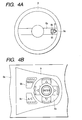
- Fig. 4A is a conceptual schematic drawing to describe an auxiliary input unit 9 placed on a hub 8a of the steering wheel 8.
- the auxiliary input unit 9 is placed leaning to the outer peripheral side of the steering wheel 8 so that the driver 3 can operate the main input unit 7 (described later) .
- the driver 3 operates the main input unit 7 while seeing the display screen 4.
- element 9a is a multi-directional operation switch having switches placed at corners and the center of a quadrangular knob. If the driver 3 presses any desired one of the switches at the four corners and the center, the switch is turned on.
- the multi-directional operation switch 9a corresponds to a joystick switch (described later) and is placed in an outermost part of the steering wheel 8.
- Element 9b is an audio switch and element 9c is an air conditioner switch; both the switches are placed inside the steering wheel 8 from the placement position of the multi-directional operation switch 9a.
- Fig. 4B is a plan schematic drawing as actual design of the auxiliary input unit 9 placed on the steering wheel 8 based on the conceptual drawing of Fig. 4A.
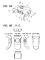
- Fig. 5 is a plan view of the main input unit 7 from the top thereof
- Fig. 6A is a perspective view of the main input unit 7
- Fig. 7 is a cross-sectional schematic representation taken on line VII-VII in Fig. 5.
- element 11 is a jog dial rotating horizontally relative to the top face of the arm rest 6 in which the main input unit 7 is placed
- elements 12A, 12B, and 12C are seesaw operation switches (operation switches) placed on one side of the main input unit 7, namely, the outer side of one leg part 13b placed upright in a direction almost at right angles to the top face of the arm rest 6.
- a first-layer screen is displayed with vehicle-installed instrument selection icons (indicators) A to F of a menu screen (described later) arranged like a horizontal ellipse as shown in Fig. 8, as the driver 3 rotates the jog dial 11, the cursor moves over the icons A to F and as the driver 3 turns on either of left and right determination switches 20 placed in a pair, the function corresponding to the icon A to F is selected. That is, any function of AIR CONDITIONER A, AUDIO B, MAP C, MAINTENANCE D, VEHICLE MEMO E, or RUN DATA F is selected.
- the operation switches 12A, 12B, and 12C are function selection switches for the driver 3 to perform selection operation in indicators displayed in six display areas X1, X2, Y1, Y2, Z1, and Z2 displayed in the upper part of each of second-layer screens (Fig. A, Fig. B, Fig. C, Fig. D, Fig. E, and Fig. F) into which the first-layer screen (Fig. 8) operated by the jog dial 11 is switched as the driver 3 turns on the determination switch 20 when the first-layer screen is displayed.
- the operation switches 12A, 12B, and 12C are placed on an almost vertical plane formed on the front end side of a main unit case 13.
- the driver 3 grasps the main unit case 13 with his or her left palm, naturally his or her thumb touches the jog dial 11 projecting from the side of the main input unit 7, his or her forefinger touches the operation switch 12C, his or her middle finger touches the operation switch 12B, and his or her third finger touches the operation switch 12A with the main unit case 13 grasped tightly with his or her palm, so that the driver 3 can easily emphasize all fingertips and can reliably operate the operation switches 12A, 12B, and 12C.
- the operation switch 12C operated with the forefinger is assigned to selection of an often used control target; the operation switch 12B operated with the middle finger is assigned to selection of a second often used control target; and the operation switch 12A operated with the third finger is assigned to selection of a third often used control target, thereby improving operability.
- Element 13 is a main unit case of the main input unit 7, and has a palm support part 13a placed in parallel with the top face of the arm rest 6 and a pair of legs 13b and 13c extended downward from the front end and the rear end of the palm support part 13a and attached to the front end part of the arm rest 6.
- the palm support part 13a is provided with the jog dial 11 and a joystick switch (multi-directional operation switch) 30.
- a recess part 15 is formed in the proximity of the center of the top face of the main unit case 13, and a joystick switch operation part 14 is placed so that the top of the joystick switch operation part 14 does not project upward from the upper opening end of the recess part 15.
- the joystick switch 30 may be any if it can be used as a scroll key; as this kind of switch, for example, a trackball, track pad, a floating switch, or the like is available.
- the recess part 15 is a cone-shaped bottomless recess part formed in the top face of the main unit case 13 so as to surround the periphery of the joystick switch operation part 14.
- Element 17 is an insertion hole made in the center of the recess part 15 into which the joystick switch operation part 14 is inserted.
- Fig. 7 is a sectional view taken on line VII-VII in Fig. 5 and is a schematic representation to show the schematic longitudinal cross section of the main input unit 7.
- element 18 is rotation operation detection unit for detecting rotation operation of the jog dial 11
- element 19 is a joystick switch operation detection unit for detecting operation of the joystick switch operation part 14.
- Element 21 is a circuit board where the rotation operation detection unit 18, the joystick switch operation detection unit 19, mechanical parts of the operation switches 12A, 12B, and 12C, and the like in the main unit case 13 are installed for electric connection.
- the main unit case 13 of the main input unit 7 forms a bridge shape and the main input unit 7 is fixed at both end parts in the length direction to the front end side of the arm rest 6 and is placed along the back and forth direction of the vehicle like a hand grip.
- the recess part 15 is formed in the proximity of the center of the top face of the main unit case 13 as described above, and is formed at the center with the insertion hole 17 into which the joystick switch operation part 14 is inserted.
- the joystick switch operation part 14 is placed upright in the up direction of the main input unit 7 and is freely swung back and forth and from side to side with a finger of the driver 3, so that the display screened on the display screen 4 is scrolled and the cursor displayed thereon is moved in response to swinging of the joystick switch operation part 14 .
- the determination switch 20 is turned on, then the function displayed on the display screen 4 is selected and determined.
- the joystick switch operation part 14 has a diameter and a shape not hindering swinging of the joystick switch operation part 14.
- Fig. 8 shows a menu screen switched as the jog dial 11 is rotated.
- the vehicle-installed instrument selection icons (indicators) of AIR CONDITIONER A, AUDIO B, MAP C, MAINTENANCE D, VEHICLE MEMO E, and RUN DATA F are displayed throughout the screen like a horizontal ellipse on the display screen 4.
- the driver 3 rotates the jog dial 11
- the colors of the icons A, B, C, D, E, and F are changed in order accordingly.
- the driver 3 turns on the determination switch 20, whereby the function corresponding to the icon is selected and determined. That is, any function of AIR CONDITIONER A, AUDIO B, MAP C, MAINTENANCE D, VEHICLE MEMO E, or RUN DATA F is selected, whereby switching operation is performed.
- the display screens shown in Figs. 9A, 9B, 9C, 9D, 9E, and 9F correspond to second-layer screens (operation screens of AIR CONDITIONER A, AUDIO B, MAP C, MAINTENANCE D, VEHICLE MEMO E, and RUN DATA F) when the selection screen of the jog dial 11 (menu screen) is the first-layer screen.
- Each of the second-layer screens is divided into first to fourth display areas 4a to 4d.
- the first display area 4a at the center of the display screens a visually understandable image of the current control target being selected (AIR CONDITIONER, AUDIO, MAP, MAINTENANCE, VEHICLE MEMO, or RUN DATA).
- the second and third display areas 4b and 4c at the left and the right of the first display area 4a display the current control state and the current condition data in real time.
- the fourth display area 4d on the top of the display screens a switch change area where selection operation of the operation switches 12A, 12B, and 12C is performed.
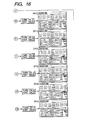
- Fig. 10 is a schematic representation to schematically illustrate the whole state transition from the menu screen to each control screen in a simple and easy-to-understand manner.
- the switch change area of the fourth display area 4d is divided into six switch display areas X1, X2, Y1, Y2, Z1, and Z2.
- the switch display areas X1 and X2 indicate areas selected by operating the operation switch 12A placed at the left of the operation switches 12A, 12B, and 12C;
- the switch display areas Y1 and Y2 indicate areas selected by operating the operation switch 12B placed at the center of the operation switches 12A, 12B, and 12C;
- the switch display areas Z1 and Z2 indicate areas selected by operating the operation switch 12C placed at the right of the operation switches 12A, 12B, and 12C.
- the driver 3 pulls up the operation switch 12A, for example, the track number of a CD is changed to a larger track number; if the driver 3 presses down the operation switch 12A, for example, the track number of a CD is changed to a smaller track number.
- the driver 3 pulls up the operation switch 12B, the source of a CD is applied; and if the driver 3 presses down the operation switch 12B, tone control is applied.
- the volume is increased; and if the driver 3 presses down the operation switch 12C, the volume is lessened.
- Fig. 11 is a whole switch layout schematic representation of the auxiliary input unit 9 placed on the hub 8a of the steering wheel 8 of the vehicle shown in Fig. 4.
- the auxiliary input unit 9 has the operation switches 9b and 9c corresponding to the generally frequently used AIR CONDITIONER and AUDIO machine selection icons of the vehicle-installed instrument selection icons (indicators) of AIR CONDITIONER A, AUDIO B, MAP C, MAINTENANCE D, VEHICLE MEMO E, and RUN DATA F switched and made selectable as the jog dial 11 is operated.
- the multi-directional operation switch 9a is a scroll switch (corresponding to the joystick switch 30) for control selection executed after function selection is executed by operating the operation switch 9b, 9c. Which of the main input unit 7 and the auxiliary input unit 9 is to be assigned priority when an ignition switch is turned on is determined as switching operation of a set switch (not shown) is performed.
- the driver 3 can press any one of the four corners of the multi-directional operation switch 9a for scrolling up and down and from side to side. If the driver 3 uses the multi-directional operation switch 9a to move the cursor to any one of the six switch display areas X1, X2, Y1, Y2, Z1, and Z2 shown in Fig. 13 and then presses the center (part represented as E in Fig. 11) of the multi-directional operation switch 9a, the switch display area is selected and determined.
- step ST10 when the driver 3 turns on the ignition switch (step ST10), an opening screen appears (step ST11) and the display state of a default screen at step ST12 is entered.
- the default screen always displays an image for the main input unit 7 or the auxiliary input unit 9, whichever is assigned priority. If the driver 3 does not operate any switch, steps ST12, ST13, and ST14 5 are repeated in order every predetermined time.
- step ST13 whether or not either the operation switch 9b or 9c of the auxiliary input unit 9 is turned on within a predetermined time is determined. If it is determined that the operation switch is not turned on, control goes to step ST14 and whether or not the jog dial 11 of the main input unit 7 is operated within a predetermined time is determined. If it is determined that the jog dial 11 is not operated, control returns to step ST12.
- step ST13 If it is determined at step ST13 that either the operation switch 9b or 9c of the auxiliary input unit 9 is turned on within the predetermined time, the screen is switched to the second-layer screen corresponding to the operation switch 9b or 9c turned on (later described in detail with reference to Fig. 14) (step ST15).
- step ST15 When a predetermined time has elapsed since the screen was switched to the second-layer screen, control returns to step ST12.
- step ST14 If it is determined at step ST14 that the jog dial 11 of the main input unit 7 is operated within the predetermined time, the screen is switched to the first-layer screen, for example, the screen in Fig. 8 (step ST15) .
- step ST15 When a predetermined time has elapsed since the screen was switched to the first-layer screen, control returns to step ST12.
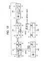
- Fig. 13 shows the state transition of a part of each control screen in the image displayed on the display screen 4 when the driver 3 turns on the AIR CONDITIONER operation switch 9c of the auxiliary input unit 9; it is the same as the switch change area of the fourth display area 4d shown in Figs. 9 and 10.
- the switch display areas X1 and X2 of the six switch display areas X1, X2, Y1, Y2, Z1 and Z2 indicate switch display areas for controlling the temperature, the air quantity, etc., of the left (passenger seat side) ; the switch display areas Z1 and Z2 indicate switch display areas for controlling the temperature, the air quantity, and the like, of the right (driver's seat side); and the switch display areas Y1 and Y2 at the center indicate areas for selecting control common to the left and the right.
- a control screen indicated by M1 in Fig. 13 is displayed in the switch change area 4d of the display screen 4. That is, a temperature increase set switch of the passenger seat is displayed in the switch display area X1 and a temperature decrease set switch of the passenger seat is displayed in the switch display area X2. A left and right separate selection switch is displayed in the switch display area Y1 and a rear seat air blowing set switch is displayed in the switch display area Y2. Further, a temperature increase set switch is displayed in the switch display area Z1 and a temperature decrease set switch is displayed in the switch display area Z2.
- a control screen indicated by M2 is displayed. That is, an air quantity increase set switch is displayed in the switch display area X1 and an air quantity decrease set switch is displayed in the switch display area X2.
- a rear seat air blowing start selection switch is displayed in the switch display area Z1.
- a control screen indicated by M3 is displayed. That is, a front DEF set switch is displayed in the switch display area X1 and a rear DEF set switch is displayed in the switch display area X2. An air outlet selection switch is displayed in the switch display area Y2. Further, an outside air taking-in selection switch is displayed in the switch display area Z1 and an inside air circulation selection switch is displayed in the switch display area Z2.
- a control screen indicated by M4 is displayed. That is, a passenger seat air blowing selection switch is displayed in the switch display area X1 and a driver's seat air blowing selection switch is displayed in the switch display area Z1.
- a control screen indicated by M5 is displayed. That is, a blown air quantity increase set switch is displayed in the switch display area X1 and a blown air quantity decrease set switch is displayed in the switch display area X2.
- An air conditioner selection switch is displayed in the switch display area Y1 and an air conditioner economy mode set switch is displayed in the switch display area Y2. Further, an air conditioner auto operation mode selection switch is displayed in the switch display area Z1 and an air conditioner stop switch is displayed in the switch display area Z2. If the driver 3 presses the center of the multi-directional operation switch 9a after the control screen is displayed, the screen returns to the control screen indicated by M1.
- the whole image of the auxiliary input unit 9 is displayed on the display screen 4. If the driver 3 then turns on the operation switch 9b twice, the display mode of the control screen is switched to the mode indicated by N1 and the display color of the display portion of "XXX NO. 1" is changed, indicating that "XXX NO. 1" is selected.
- the driver 3 then turns on the switch indicated by C, of the multi-directional operation switch 9a once, the display color of the display portion of "*** BROADCAST” is changed and the display mode of the control screen indicates that "*** BROADCAST” indicated by N2 is selected.
- the display color of the display portion of "RADIO ***” is changed and the display mode of the control screen indicates that "RADIO ***” indicated by N3 is selected.
- the display color of the display portion of "***” is changed and the display mode of the control screen indicates that "***” indicated by N4 is selected.
- the display color of the portion surrounded by a solid frame X1 at the right of the control screen is changed and the volume is increased.
- the screen is switched to the display image of the main input unit 7 of the default screen in a predetermined time.
- the driver 3 turns on the switch indicated by B, of the multi-directional operation switch 9a once in the display mode indicated by N1
- the display color of the portion surrounded by a solid frame X2 at the right of the control screen is changed and the volume is lessened.
- the screen is switched to the display image of the main input unit 7 of the default screen in a predetermined time.
- the driver when the driver concentrates on driving and it becomes necessary to operate the audio components or the air conditioner the driver can easily find out the position of the main input unit 7 by groping for the main input unit 7 with the recess part H as a guide although the driver turns his or her eyes forward. Then, the driver inserts his or her fingertip into the recess part H formed on the lower side of the main unit case 13 and grasps the main input unit 7 tightly with his or her palm, whereby naturally the periphery of the jog dial 11 strikes the finger roots.
- the display color of each entry in the menu display screened on the display screen 4 is changed.
- the driver can turn on the determination switch 20, thereby easily entering the function screen. Since the driver also reaches the operation switches 12A, 12B, and 12C naturally with his or her fingertip in a grip state, it is also made possible for the driver to easily operate the operation switches 12A, 12B, and 12C.
- the joystick switch operation part 14 is placed in the main input unit 7 so that the upper end part of the joystick switch operation part 14 does not project from the top face of the main unit case 13, so that when the driver grasps the main input unit 7, the joystick switch operation part 14 is not swung or pressed by mistake. Thus, the driver cannot operate the joystick switch operation part 14 unless he or she intentionally inserts his or her finger into the recess part 15 formed in the center of the top face of the main unit case 13.
- the driver can grasp the main input unit 7 easily in a groping state, so that it is made possible for the driver to reliably operate the jog dial 11 and the operation switches; the operability can be improved.
- the driver can operate the joystick switch operation part 14 in a stable state, the driver can precisely convey motion of his or her thumb to the joystick switch operation part 14 and can operate the joystick switch operation part 14 as he or she intends without receiving the effect of vibration of the vehicle or a swinging occurring unexpectedly during operation.
- the determination switches 20 are placed at the front of the jog dial 11 contiguously therewith, but may be placed at any positions, needless to say.
- a determination switch denoted by numeral 20' may be placed at the center of the rear end of the upper side of the main unit case 13 as shown in Fig. 17.
- the driver 3 can operate the switches such as the jog dial 11, with the main unit case 13 grasped with his or her palm and pushes the determination switch 20' in the proximity of the wrist of the palm in the state.
- Fig. 18 is an exploded view of a main input unit 50
- Fig. 19 is a plan view of the main input unit 50 viewed from above
- Fig. 20 is a right side view of the main input unit 50 in Fig. 19
- Fig. 21 is a sectional view taken on line XXI-XXI in Fig. 19.
- element 51 is a lower case shaped like a bridge formed in a lower side with a space H having the same function as the space shown in Fig. 6.
- element 52 is an upper case engaged with the lower case 51 from above. Both the lower case 51 and the upper case 52 form a main unit case corresponding to the main unit case 13 in Fig. 6.
- the upper case 52 is formed on opposed sides with a pair of first notches 52a and a pair of second notches 52b wider than the first notches 52a below the first notches 52a continuously.
- a jog dial 55a (described below) is exposed from both the first notches 52a so that it can be operated from the outside.
- Operation parts 58a and 59a of the determination switches 58 and 59 (described later) are placed in the second notches 52b, and circular arc parts of both the operation parts 58a and 59a are projected to the outside of the outer peripheral surface of the jog dial 55a (described below) . That is, the driver can easily push down the operation part 58a, 59a simply by downward moving his or her fingertip operating the jog dial 55a.
- a plurality of window parts 52d are placed on an almost perpendicular plane formed on the front end side of the upper case 52 and operation switches 57A, 57B and 57C (corresponding to the operation switches 12A, 12B and 12C in Fig. 6 and each having the same functions as the operation switches 12A, 12B, and 12C) are placed in the window parts 52d.
- a first circuit board 53 and a second circuit board 54 are housed in the space surrounded by the lower case 51 and the upper case 52.
- a jog dial switch 55 operated by the jog dial 55a (corresponding to the jog dial 11 in Fig. 6) and joystick switch operation detection unit 56 to which a joystick switch operation part 56a and an auxiliary ring member 56b are attached are attached to the first circuit board 53.
- the operation switches 57A to 57C are attached to the second circuit board 54.
- a palm support part 52e is formed on the top face of the upper case 52 and a pair of leg parts 52f and 52g is extended downward from the front end and the rear end of the palm support part 52e.
- a recess part 60 is formed in the proximity of the center of the top face of the palm support part 52e.
- the joystick switch operation part 56a and the auxiliary ring member 56b are placed in the recess part 60 so that the upper end parts of the joystick switch operation part 56a and the auxiliary ring member 56b do not project upward from the upper opening end of the recess part 60.
- Element 61 is an insertion hole made in the center of the recess part 60 into which the joystick switch operation part 56a is inserted.
- the operation parts 58a, 59a is shaped roughly like a circular arc, and wall parts 58b, 59b is formed upright along the outer peripheral margin of the operation parts 58a, 59a.
- the determination switches 58 and 59 are assembled, they are disposed so that the lower side of the outer peripheral margin of the jog dial 55a is positioned on the inner sides of the wall parts 58b and 59b.
- the operation part 58a, 59a is formed on sides with a pair of circular bosses 58c, 59c, and the pairs of circular bosses 58c and 59c are rotatably supported by pairs of support members 51a and 51b placed corresponding to the lower case 51 for rotation.
- the operation part 58a or 59a rotates on the circular boss 58c or 59c by a predetermined angle and is displaced from the position indicated by the solid line to the position indicated by the dashed line.
- the recess part is formed in the lower part of the input apparatus according to the invention, so that the driver can easily find out the position of the operation dial with the recess part as a guide and can easily operate the dial.
- the palm support part is attached to the leg parts almost at right angle, whereby it is made possible for the operator to emphasize his or her finger and reliably operate the switches.
- the operated switch positions and the display screen can be matched with each other, so that the driver can easily understand the switch positions sensuously, namely, simply by seeing the display screen.
- the user uses the operation dial to execute menu selection based on the indicators displayed on the display screen and uses the operation switches to select a function of the vehicle-installed instrument, so that the driver can easily and sensuously understand the switch position to be pressed and dial selection operation while seeing the image displayed on the display screen.
- the auxiliary input unit attached to the steering wheel there is provided with the selection function of selecting a frequently used indicator among the indicators selected by operating the operation dial and displayed on the display screen. Therefore, the steering wheel always grasped by the driver is provided with the switch function involved in the frequently used indicator, whereby switch operation is facilitated.
- the determination switch is placed in the proximity of the operation dial for determining any desired indicator made selectable by operating the operation dial, thereby enabling the driver to easily operate the determination switch with his or her finger operating the operation dial.
- the determination switch has the operation part being put on the operation dial and projected from the peripheral surface of the operation dial to the outside, thereby enabling the driver to more easily the operation part simply by a little moving his or her finger operating the operation dial.
Landscapes
- Engineering & Computer Science (AREA)
- General Engineering & Computer Science (AREA)
- Theoretical Computer Science (AREA)
- Human Computer Interaction (AREA)
- Physics & Mathematics (AREA)
- General Physics & Mathematics (AREA)
- Mechanical Engineering (AREA)
- Switches With Compound Operations (AREA)
- Position Input By Displaying (AREA)
- Instrument Panels (AREA)
- Rotary Switch, Piano Key Switch, And Lever Switch (AREA)
Applications Claiming Priority (4)
| Application Number | Priority Date | Filing Date | Title |
|---|---|---|---|
| JP2002064262 | 2002-03-08 | ||
| JP2002064262 | 2002-03-08 | ||
| JP2002122766A JP2003327059A (ja) | 2002-03-08 | 2002-04-24 | 車両用入力装置 |
| JP2002122766 | 2002-04-24 |
Publications (3)
| Publication Number | Publication Date |
|---|---|
| EP1343113A2 true EP1343113A2 (de) | 2003-09-10 |
| EP1343113A3 EP1343113A3 (de) | 2004-02-11 |
| EP1343113B1 EP1343113B1 (de) | 2006-07-05 |
Family
ID=27759758
Family Applications (1)
| Application Number | Title | Priority Date | Filing Date |
|---|---|---|---|
| EP03004961A Expired - Lifetime EP1343113B1 (de) | 2002-03-08 | 2003-03-10 | Eingabegerät für in einem Fahrzeug eingebaute Instrumente |
Country Status (4)
| Country | Link |
|---|---|
| US (1) | US6903652B2 (de) |
| EP (1) | EP1343113B1 (de) |
| JP (1) | JP2003327059A (de) |
| DE (1) | DE60306561T2 (de) |
Cited By (13)
| Publication number | Priority date | Publication date | Assignee | Title |
|---|---|---|---|---|
| WO2005077701A1 (de) * | 2004-02-13 | 2005-08-25 | Daimlerchrysler Ag | Bedienvorrichtung für ein fahrzeug |
| DE102004010205B3 (de) * | 2004-03-02 | 2005-10-20 | Siemens Ag | Bedienelement, insbesondere zur Steuerung eines medizinischen Systems |
| GB2422184A (en) * | 2005-01-11 | 2006-07-19 | Mssdesign Ltd | Actual or virtual dial on a vehicle steering wheel for display indicator movement and selection |
| EP1826056A1 (de) * | 2006-02-24 | 2007-08-29 | Harman Becker Automotive Systems GmbH | Multifunktionseingabegerät |
| EP1911629A1 (de) * | 2005-07-29 | 2008-04-16 | HONDA MOTOR CO., Ltd. | Betätigungsvorrichtung für fahrzeug |
| FR2909045A3 (fr) * | 2006-11-24 | 2008-05-30 | Renault Sas | Agencement de commandes d'equipements de vehicule automobile |
| WO2008092598A1 (de) * | 2007-01-30 | 2008-08-07 | Johnson Controls Gmbh | Kfz-anzeigeinstrument mit positionveränderlichen bedienelement |
| WO2008138491A1 (de) * | 2007-05-14 | 2008-11-20 | Bayerische Motoren Werke Aktiengesellschaft | Bedieneinrichtung |
| WO2009012856A1 (de) * | 2007-07-25 | 2009-01-29 | Daimler Ag | Bedieneinrichtung für ein fahrzeug |
| FR2930653A1 (fr) * | 2008-04-23 | 2009-10-30 | Peugeot Citroen Automobiles Sa | Dispositif de reglage de plusieurs fonctions d'un systeme, notamment d'un systeme embarque dans un vehicule automobile |
| GB2476837A (en) * | 2010-01-12 | 2011-07-13 | Worthington Sharpe Ltd | Rotatable Input Device |
| EP3225458A1 (de) * | 2016-04-01 | 2017-10-04 | Grammer Ag | Bedienelemente in einer armlehnenvorrichtung |
| EP2930046B1 (de) * | 2012-12-07 | 2022-03-30 | Kabushiki Kaisha Tokai Rika Denki Seisakusho | Schaltvorrichtung |
Families Citing this family (60)
| Publication number | Priority date | Publication date | Assignee | Title |
|---|---|---|---|---|
| US7126580B2 (en) | 2002-06-13 | 2006-10-24 | Panasonic Automotive Systems Company Of America | Interface for a multifunctional system |
| JP4026071B2 (ja) * | 2003-09-25 | 2007-12-26 | ソニー株式会社 | 車載装置及びコンテンツ提供方法 |
| US20050073195A1 (en) * | 2003-10-06 | 2005-04-07 | Popilek Mark E. | Steering wheel mounted scroll wheel and method |
| DE10360664A1 (de) * | 2003-12-23 | 2005-07-28 | Daimlerchrysler Ag | Bediensystem für ein Kraftfahrzeug |
| GB2409664A (en) * | 2003-12-29 | 2005-07-06 | Nokia Corp | A key arrangement |
| JP2005202811A (ja) * | 2004-01-19 | 2005-07-28 | Nippon Seiki Co Ltd | パルス発生装置及びその装置を備えた車両用表示装置 |
| US7373229B2 (en) * | 2004-07-29 | 2008-05-13 | Gm Global Technology Operations, Inc. | Multifunction control system |
| US20060092129A1 (en) * | 2004-10-20 | 2006-05-04 | Visteon Global Technologies, Inc. | Human machine interface for vehicle |
| US20060082545A1 (en) * | 2004-10-20 | 2006-04-20 | Visteon Global Technologies, Inc. | Human machine interface for vehicle including proximity sensor |
| US20060092130A1 (en) * | 2004-10-20 | 2006-05-04 | Visteon Global Technologies, Inc. | Human machine interface for a vehicle including touch sensor |
| JP2006298241A (ja) * | 2005-04-22 | 2006-11-02 | Toyota Motor Corp | 車両用表示装置 |
| JP4700432B2 (ja) * | 2005-07-29 | 2011-06-15 | 本田技研工業株式会社 | 車両用操作装置 |
| JP4650247B2 (ja) * | 2005-12-07 | 2011-03-16 | 株式会社デンソー | カーナビゲーションシステム |
| US7742857B2 (en) * | 2005-12-07 | 2010-06-22 | Mazda Motor Corporation | Automotive information display system |
| US7999790B2 (en) * | 2006-05-12 | 2011-08-16 | Sikorsky Aircraft Corporation | Multi-functional mission grip for a vehicle |
| JP4888063B2 (ja) * | 2006-11-08 | 2012-02-29 | 株式会社デンソー | 手動操作装置 |
| ITMI20070140A1 (it) * | 2007-01-30 | 2008-07-31 | Campagnolo Srl | Dispositivo di interazione uomo-bicicletta |
| JP4960127B2 (ja) * | 2007-03-28 | 2012-06-27 | 株式会社デンソー | 操作デバイス |
| ITMI20070737A1 (it) * | 2007-04-12 | 2008-10-13 | Campagnolo Srl | Apparecchiatura e sistema elettronico per bicicletta e metodi relativi |
| JP5393680B2 (ja) * | 2007-09-10 | 2014-01-22 | ジョンソン・コントロールズ・ゲー・エム・ベー・ハー | 特注可能な表示機器 |
| ITMI20072407A1 (it) * | 2007-12-20 | 2009-06-21 | Campagnolo Srl | Apparecchiatura elettronica per bicicletta |
| JP5046909B2 (ja) * | 2007-12-21 | 2012-10-10 | 株式会社日本マイクロニクス | 電気試験用接触子、これを用いる電気的接続装置、及び接触子の製造方法 |
| TW200933439A (en) * | 2008-01-31 | 2009-08-01 | Compal Electronics Inc | Method and apparatus for controlling functionalities of computer system |
| JP4623391B2 (ja) * | 2008-11-07 | 2011-02-02 | 株式会社デンソー | 車載用遠隔操作装置 |
| US9641678B2 (en) * | 2009-01-29 | 2017-05-02 | Ford Global Technologies, Llc | System and method for interrupting an instructional prompt to signal upcoming input over a wireless communication link |
| JP5279597B2 (ja) | 2009-04-24 | 2013-09-04 | 株式会社デンソー | 車両用操作装置 |
| JP2011113345A (ja) * | 2009-11-27 | 2011-06-09 | Fujitsu Ten Ltd | 車載表示システム |
| US8457839B2 (en) * | 2010-01-07 | 2013-06-04 | Ford Global Technologies, Llc | Multi-display vehicle information system and method |
| JP5204163B2 (ja) * | 2010-07-28 | 2013-06-05 | 本田技研工業株式会社 | インターフェース装置 |
| US20120041633A1 (en) | 2010-08-16 | 2012-02-16 | Ford Global Technologies, Llc | Systems and methods for regulating control of a vehicle infotainment system |
| US8559932B2 (en) | 2010-12-20 | 2013-10-15 | Ford Global Technologies, Llc | Selective alert processing |
| EP2518591B1 (de) | 2011-04-25 | 2018-05-30 | LS Automotive Technologies Co., Ltd. | Haptische Lenkradschaltvorrichtung und haptisches Lenkradschaltsystem damit |
| EP2518592B1 (de) | 2011-04-25 | 2017-07-26 | Daesung Electric Co., Ltd | Haptische Lenkradschaltvorrichtung |
| JP5870841B2 (ja) * | 2012-05-17 | 2016-03-01 | 株式会社デンソー | 車両用表示装置 |
| JP5971700B2 (ja) * | 2012-05-17 | 2016-08-17 | アルパイン株式会社 | 表示装置 |
| JP2014046867A (ja) * | 2012-08-31 | 2014-03-17 | Sony Corp | 入力装置 |
| JP5998885B2 (ja) * | 2012-11-30 | 2016-09-28 | マツダ株式会社 | 車両用入力装置 |
| JP5678948B2 (ja) * | 2012-12-12 | 2015-03-04 | 株式会社デンソー | 車両用表示装置およびプログラム |
| US9007199B2 (en) | 2013-01-29 | 2015-04-14 | Honda Motor Co., Ltd. | Drive mode selector |
| JP5880468B2 (ja) * | 2013-02-05 | 2016-03-09 | マツダ株式会社 | 車両用操作スイッチの脱落構造 |
| US9069396B2 (en) | 2013-03-12 | 2015-06-30 | Lightlab Imaging, Inc. | Controller and user interface device, systems, and methods |
| US8909212B2 (en) | 2013-03-14 | 2014-12-09 | Ford Global Technologies, Llc | Method and apparatus for disclaimer presentation and confirmation |
| US8862320B2 (en) | 2013-03-14 | 2014-10-14 | Ford Global Technologies, Llc | Method and apparatus for ambient lighting incoming message alert |
| JP6136627B2 (ja) * | 2013-06-24 | 2017-05-31 | マツダ株式会社 | 車両用情報表示装置 |
| US9098180B1 (en) * | 2013-08-29 | 2015-08-04 | Panasonic Automotive Systems Company Of America, Division Of Panasonic Corporation Of North America | User interface and method for personalized radio station creation |
| CN104599888B (zh) * | 2013-11-01 | 2017-04-12 | 褚锦雄 | 五向位开关基座结构 |
| JP6156087B2 (ja) * | 2013-11-15 | 2017-07-05 | マツダ株式会社 | 車両用センターコンソール構造 |
| JP5899251B2 (ja) * | 2014-01-29 | 2016-04-06 | 本田技研工業株式会社 | 車両用入力装置 |
| JP5924355B2 (ja) * | 2014-02-10 | 2016-05-25 | トヨタ自動車株式会社 | 車両用情報表示装置 |
| JP2015176286A (ja) * | 2014-03-14 | 2015-10-05 | 株式会社デンソー | 機器操作装置 |
| DE102014216389A1 (de) * | 2014-08-19 | 2016-02-25 | BSH Hausgeräte GmbH | Bedienvorrichtung für ein Haushaltsgerät mit stabil positioniertem ringförmigen Bedienelement-Vorderteil und Haushaltsgerät mit einer derartigen Bedienvorrichtung |
| JP6627087B2 (ja) * | 2016-08-30 | 2020-01-08 | パナソニックIpマネジメント株式会社 | 入力装置 |
| CN111095393B (zh) * | 2017-09-21 | 2022-07-05 | 马自达汽车株式会社 | 车用显示装置 |
| US10858016B2 (en) * | 2017-11-02 | 2020-12-08 | Progress Rail Locomotive Inc. | Remotely operated railcar hatches |
| USD944868S1 (en) | 2018-09-07 | 2022-03-01 | Crown Equipment Corporation | Arm pad |
| USD944869S1 (en) | 2018-09-07 | 2022-03-01 | Crown Equipment Corporation | Arm pad |
| USD922279S1 (en) | 2018-10-17 | 2021-06-15 | Crown Equipment Corporation | Control pod |
| DE102020117691A1 (de) | 2020-07-06 | 2022-01-13 | Grammer Aktiengesellschaft | Lenkvorrichtung für Fahrzeuge |
| JPWO2022259888A1 (de) * | 2021-06-09 | 2022-12-15 | ||
| CN114084074A (zh) * | 2021-11-24 | 2022-02-25 | 湖南郴州汽车运输集团有限责任公司 | 城乡一体化客运车辆的车载式调度信息接收装置 |
Citations (6)
| Publication number | Priority date | Publication date | Assignee | Title |
|---|---|---|---|---|
| JPH01142958A (ja) * | 1987-11-30 | 1989-06-05 | Toshiba Corp | メモリ管理方式 |
| JPH10214543A (ja) * | 1997-01-31 | 1998-08-11 | Yazaki Corp | システムスイッチ |
| JP2000276976A (ja) * | 1999-03-25 | 2000-10-06 | Calsonic Kansei Corp | マルチファンクションスイッチ |
| DE10105177A1 (de) * | 2001-02-01 | 2002-08-14 | Caa Ag | Fahrzeugrechner-System und Bedienvorrichtung für ein Fahrzeugrechner-System |
| EP1258385A2 (de) * | 2001-05-17 | 2002-11-20 | Calsonic Kansei Corporation | Betätigungsvorrichtung in einem Fahrzeug |
| JP2003168346A (ja) * | 2001-12-03 | 2003-06-13 | Calsonic Kansei Corp | 乗り物搭載機器用操作装置 |
Family Cites Families (3)
| Publication number | Priority date | Publication date | Assignee | Title |
|---|---|---|---|---|
| US5045842A (en) * | 1989-10-23 | 1991-09-03 | Galvin James J | Computer input device |
| US6241611B1 (en) * | 1995-05-10 | 2001-06-05 | Nintendo Co., Ltd. | Function expansion device and operating device using the function expansion device |
| JPH10297391A (ja) | 1997-04-23 | 1998-11-10 | Harness Sogo Gijutsu Kenkyusho:Kk | 自動車のスイッチ装置 |
-
2002
- 2002-04-24 JP JP2002122766A patent/JP2003327059A/ja active Pending
-
2003
- 2003-03-07 US US10/383,220 patent/US6903652B2/en not_active Expired - Fee Related
- 2003-03-10 EP EP03004961A patent/EP1343113B1/de not_active Expired - Lifetime
- 2003-03-10 DE DE60306561T patent/DE60306561T2/de not_active Expired - Fee Related
Patent Citations (6)
| Publication number | Priority date | Publication date | Assignee | Title |
|---|---|---|---|---|
| JPH01142958A (ja) * | 1987-11-30 | 1989-06-05 | Toshiba Corp | メモリ管理方式 |
| JPH10214543A (ja) * | 1997-01-31 | 1998-08-11 | Yazaki Corp | システムスイッチ |
| JP2000276976A (ja) * | 1999-03-25 | 2000-10-06 | Calsonic Kansei Corp | マルチファンクションスイッチ |
| DE10105177A1 (de) * | 2001-02-01 | 2002-08-14 | Caa Ag | Fahrzeugrechner-System und Bedienvorrichtung für ein Fahrzeugrechner-System |
| EP1258385A2 (de) * | 2001-05-17 | 2002-11-20 | Calsonic Kansei Corporation | Betätigungsvorrichtung in einem Fahrzeug |
| JP2003168346A (ja) * | 2001-12-03 | 2003-06-13 | Calsonic Kansei Corp | 乗り物搭載機器用操作装置 |
Non-Patent Citations (4)
| Title |
|---|
| PATENT ABSTRACTS OF JAPAN vol. 013, no. 397 (P-928), 5 September 1989 (1989-09-05) & JP 01 142958 A (TOSHIBA CORP), 5 June 1989 (1989-06-05) * |
| PATENT ABSTRACTS OF JAPAN vol. 1998, no. 13, 30 November 1998 (1998-11-30) & JP 10 214543 A (YAZAKI CORP), 11 August 1998 (1998-08-11) & US 6 476 794 B1 (KATAOKA ICHIRO ET AL) 5 November 2002 (2002-11-05) * |
| PATENT ABSTRACTS OF JAPAN vol. 2000, no. 13, 5 February 2001 (2001-02-05) & JP 2000 276976 A (CALSONIC KANSEI CORP), 6 October 2000 (2000-10-06) * |
| PATENT ABSTRACTS OF JAPAN vol. 2003, no. 10, 8 October 2003 (2003-10-08) & JP 2003 168346 A (CALSONIC KANSEI CORP), 13 June 2003 (2003-06-13) * |
Cited By (20)
| Publication number | Priority date | Publication date | Assignee | Title |
|---|---|---|---|---|
| WO2005077701A1 (de) * | 2004-02-13 | 2005-08-25 | Daimlerchrysler Ag | Bedienvorrichtung für ein fahrzeug |
| DE102004010205B3 (de) * | 2004-03-02 | 2005-10-20 | Siemens Ag | Bedienelement, insbesondere zur Steuerung eines medizinischen Systems |
| US7113836B2 (en) | 2004-03-02 | 2006-09-26 | Siemens Aktiengesellschaft | Control device for maneuvering an apparatus |
| GB2422184A (en) * | 2005-01-11 | 2006-07-19 | Mssdesign Ltd | Actual or virtual dial on a vehicle steering wheel for display indicator movement and selection |
| CN101233013B (zh) * | 2005-07-29 | 2011-06-08 | 本田技研工业株式会社 | 车辆用操作装置 |
| EP1911629A1 (de) * | 2005-07-29 | 2008-04-16 | HONDA MOTOR CO., Ltd. | Betätigungsvorrichtung für fahrzeug |
| EP1911629A4 (de) * | 2005-07-29 | 2008-12-03 | Honda Motor Co Ltd | Betätigungsvorrichtung für fahrzeug |
| EP1826056A1 (de) * | 2006-02-24 | 2007-08-29 | Harman Becker Automotive Systems GmbH | Multifunktionseingabegerät |
| US9321348B2 (en) | 2006-02-24 | 2016-04-26 | Harman Becker Automotive Systems Gmbh | Multifunction input device |
| FR2909045A3 (fr) * | 2006-11-24 | 2008-05-30 | Renault Sas | Agencement de commandes d'equipements de vehicule automobile |
| WO2008092598A1 (de) * | 2007-01-30 | 2008-08-07 | Johnson Controls Gmbh | Kfz-anzeigeinstrument mit positionveränderlichen bedienelement |
| WO2008138491A1 (de) * | 2007-05-14 | 2008-11-20 | Bayerische Motoren Werke Aktiengesellschaft | Bedieneinrichtung |
| WO2009012856A1 (de) * | 2007-07-25 | 2009-01-29 | Daimler Ag | Bedieneinrichtung für ein fahrzeug |
| FR2930653A1 (fr) * | 2008-04-23 | 2009-10-30 | Peugeot Citroen Automobiles Sa | Dispositif de reglage de plusieurs fonctions d'un systeme, notamment d'un systeme embarque dans un vehicule automobile |
| GB2476837A (en) * | 2010-01-12 | 2011-07-13 | Worthington Sharpe Ltd | Rotatable Input Device |
| US8890814B2 (en) | 2010-01-12 | 2014-11-18 | Worthington Sharpe Limited | Input device |
| GB2476837B (en) * | 2010-01-12 | 2015-06-03 | Worthington Sharpe Ltd | Input device |
| EP2930046B1 (de) * | 2012-12-07 | 2022-03-30 | Kabushiki Kaisha Tokai Rika Denki Seisakusho | Schaltvorrichtung |
| EP3225458A1 (de) * | 2016-04-01 | 2017-10-04 | Grammer Ag | Bedienelemente in einer armlehnenvorrichtung |
| US10266071B2 (en) | 2016-04-01 | 2019-04-23 | Grammer Ag | Control elements in an armrest device |
Also Published As
| Publication number | Publication date |
|---|---|
| DE60306561D1 (de) | 2006-08-17 |
| US6903652B2 (en) | 2005-06-07 |
| US20030234764A1 (en) | 2003-12-25 |
| JP2003327059A (ja) | 2003-11-19 |
| DE60306561T2 (de) | 2006-11-16 |
| EP1343113B1 (de) | 2006-07-05 |
| EP1343113A3 (de) | 2004-02-11 |
Similar Documents
| Publication | Publication Date | Title |
|---|---|---|
| EP1343113B1 (de) | Eingabegerät für in einem Fahrzeug eingebaute Instrumente | |
| US6707387B2 (en) | Operating device for operating apparatus mounted on vehicle | |
| US7116317B2 (en) | Systems and methods for user interfaces designed for rotary input devices | |
| JP4836050B2 (ja) | 車載電子機器用入力システム | |
| JP4960127B2 (ja) | 操作デバイス | |
| US9346356B2 (en) | Operation input device for vehicle | |
| JP2000194502A (ja) | タッチ操作入力装置 | |
| JP2004127097A (ja) | 情報表示装置 | |
| JP2000149721A (ja) | 車載機器用操作装置 | |
| JP2001222271A (ja) | メニュー画面表示方法及びそれを用いた表示装置 | |
| JP4094282B2 (ja) | 乗り物搭載機器用操作装置 | |
| JP4792683B2 (ja) | 車両用操作スイッチ装置 | |
| JP2015189413A (ja) | 車両用操作装置 | |
| JP2007290559A (ja) | 車両用入力装置 | |
| JP2004299539A (ja) | 車載用入力装置 | |
| US8368644B2 (en) | Operation feeling giving input device | |
| JP4771237B2 (ja) | 車両用操作装置 | |
| JPH08127267A (ja) | 車載機器の操作装置 | |
| JP2009301082A (ja) | 操作感触付与型入力装置 | |
| JP5998885B2 (ja) | 車両用入力装置 | |
| JP2000235453A (ja) | 位置データ出力装置 | |
| JP4738619B2 (ja) | 車載用操作装置 | |
| WO2015129238A1 (ja) | 車両用設定装置 | |
| JP2000276976A (ja) | マルチファンクションスイッチ | |
| JP2005317303A (ja) | 車両用スイッチ装置 |
Legal Events
| Date | Code | Title | Description |
|---|---|---|---|
| PUAI | Public reference made under article 153(3) epc to a published international application that has entered the european phase |
Free format text: ORIGINAL CODE: 0009012 |
|
| AK | Designated contracting states |
Kind code of ref document: A2 Designated state(s): AT BE BG CH CY CZ DE DK EE ES FI FR GB GR HU IE IT LI LU MC NL PT SE SI SK TR |
|
| AX | Request for extension of the european patent |
Extension state: AL LT LV MK RO |
|
| PUAL | Search report despatched |
Free format text: ORIGINAL CODE: 0009013 |
|
| AK | Designated contracting states |
Kind code of ref document: A3 Designated state(s): AT BE BG CH CY CZ DE DK EE ES FI FR GB GR HU IE IT LI LU MC NL PT SE SI SK TR |
|
| AX | Request for extension of the european patent |
Extension state: AL LT LV MK RO |
|
| RIC1 | Information provided on ipc code assigned before grant |
Ipc: 7H 01H 19/04 B Ipc: 7G 06F 3/02 A Ipc: 7B 60K 37/06 B Ipc: 7G 06K 11/18 B |
|
| 17P | Request for examination filed |
Effective date: 20040317 |
|
| 17Q | First examination report despatched |
Effective date: 20040519 |
|
| AKX | Designation fees paid |
Designated state(s): DE FR GB |
|
| GRAP | Despatch of communication of intention to grant a patent |
Free format text: ORIGINAL CODE: EPIDOSNIGR1 |
|
| GRAS | Grant fee paid |
Free format text: ORIGINAL CODE: EPIDOSNIGR3 |
|
| GRAA | (expected) grant |
Free format text: ORIGINAL CODE: 0009210 |
|
| RIC1 | Information provided on ipc code assigned before grant |
Ipc: B60K 37/06 20060101ALI20060519BHEP Ipc: G06F 3/033 20060101ALI20060519BHEP Ipc: G06K 11/06 20060101ALI20060519BHEP Ipc: H01H 19/04 20060101ALI20060519BHEP Ipc: G06F 3/02 20060101AFI20060519BHEP |
|
| AK | Designated contracting states |
Kind code of ref document: B1 Designated state(s): DE FR GB |
|
| REG | Reference to a national code |
Ref country code: GB Ref legal event code: FG4D |
|
| REF | Corresponds to: |
Ref document number: 60306561 Country of ref document: DE Date of ref document: 20060817 Kind code of ref document: P |
|
| ET | Fr: translation filed | ||
| PLBE | No opposition filed within time limit |
Free format text: ORIGINAL CODE: 0009261 |
|
| STAA | Information on the status of an ep patent application or granted ep patent |
Free format text: STATUS: NO OPPOSITION FILED WITHIN TIME LIMIT |
|
| 26N | No opposition filed |
Effective date: 20070410 |
|
| PGFP | Annual fee paid to national office [announced via postgrant information from national office to epo] |
Ref country code: GB Payment date: 20080305 Year of fee payment: 6 |
|
| PGFP | Annual fee paid to national office [announced via postgrant information from national office to epo] |
Ref country code: DE Payment date: 20080306 Year of fee payment: 6 Ref country code: FR Payment date: 20080311 Year of fee payment: 6 |
|
| GBPC | Gb: european patent ceased through non-payment of renewal fee |
Effective date: 20090310 |
|
| REG | Reference to a national code |
Ref country code: FR Ref legal event code: ST Effective date: 20091130 |
|
| PG25 | Lapsed in a contracting state [announced via postgrant information from national office to epo] |
Ref country code: DE Free format text: LAPSE BECAUSE OF NON-PAYMENT OF DUE FEES Effective date: 20091001 |
|
| PG25 | Lapsed in a contracting state [announced via postgrant information from national office to epo] |
Ref country code: FR Free format text: LAPSE BECAUSE OF NON-PAYMENT OF DUE FEES Effective date: 20091123 Ref country code: GB Free format text: LAPSE BECAUSE OF NON-PAYMENT OF DUE FEES Effective date: 20090310 |