US10266071B2 - Control elements in an armrest device - Google Patents

Control elements in an armrest device Download PDF

Info

Publication number
US10266071B2
US10266071B2 US15/472,487 US201715472487A US10266071B2 US 10266071 B2 US10266071 B2 US 10266071B2 US 201715472487 A US201715472487 A US 201715472487A US 10266071 B2 US10266071 B2 US 10266071B2
Authority
US
United States
Prior art keywords
control element
control
armrest device
control elements
actuated
Prior art date
Legal status (The legal status is an assumption and is not a legal conclusion. Google has not performed a legal analysis and makes no representation as to the accuracy of the status listed.)
Active
Application number
US15/472,487
Other versions
US20170282762A1 (en
Inventor
Daniel Kleiber
Thomas Haller
Florian SCHANDERL
Current Assignee (The listed assignees may be inaccurate. Google has not performed a legal analysis and makes no representation or warranty as to the accuracy of the list.)
Grammer AG
Original Assignee
Grammer AG
Priority date (The priority date is an assumption and is not a legal conclusion. Google has not performed a legal analysis and makes no representation as to the accuracy of the date listed.)
Filing date
Publication date
Priority claimed from DE202016101747.5U external-priority patent/DE202016101747U1/en
Priority claimed from DE102016106030.5A external-priority patent/DE102016106030B4/en
Application filed by Grammer AG filed Critical Grammer AG
Assigned to GRAMMER AG reassignment GRAMMER AG ASSIGNMENT OF ASSIGNORS INTEREST (SEE DOCUMENT FOR DETAILS). Assignors: Klieber, Daniel, HALLER, THOMAS, Schanderl, Florian
Publication of US20170282762A1 publication Critical patent/US20170282762A1/en
Application granted granted Critical
Publication of US10266071B2 publication Critical patent/US10266071B2/en
Assigned to GRAMMER AG reassignment GRAMMER AG CHANGE OF ADDRESS Assignors: GRAMMER AG
Active legal-status Critical Current
Anticipated expiration legal-status Critical

Links

Images

Classifications

    • BPERFORMING OPERATIONS; TRANSPORTING
    • B60VEHICLES IN GENERAL
    • B60NSEATS SPECIALLY ADAPTED FOR VEHICLES; VEHICLE PASSENGER ACCOMMODATION NOT OTHERWISE PROVIDED FOR
    • B60N2/00Seats specially adapted for vehicles; Arrangement or mounting of seats in vehicles
    • B60N2/02Seats specially adapted for vehicles; Arrangement or mounting of seats in vehicles the seat or part thereof being movable, e.g. adjustable
    • B60N2/0224Non-manual adjustments, e.g. with electrical operation
    • B60N2/0226User interfaces specially adapted for seat adjustment
    • B60N2/0228Hand-activated mechanical switches
    • BPERFORMING OPERATIONS; TRANSPORTING
    • B60VEHICLES IN GENERAL
    • B60NSEATS SPECIALLY ADAPTED FOR VEHICLES; VEHICLE PASSENGER ACCOMMODATION NOT OTHERWISE PROVIDED FOR
    • B60N2/00Seats specially adapted for vehicles; Arrangement or mounting of seats in vehicles
    • B60N2/75Arm-rests
    • B60N2/79Adaptations for additional use of the arm-rests
    • B60N2/797Adaptations for additional use of the arm-rests for use as electrical control means, e.g. switches
    • BPERFORMING OPERATIONS; TRANSPORTING
    • B60VEHICLES IN GENERAL
    • B60NSEATS SPECIALLY ADAPTED FOR VEHICLES; VEHICLE PASSENGER ACCOMMODATION NOT OTHERWISE PROVIDED FOR
    • B60N2/00Seats specially adapted for vehicles; Arrangement or mounting of seats in vehicles
    • B60N2/56Heating or ventilating devices
    • BPERFORMING OPERATIONS; TRANSPORTING
    • B60VEHICLES IN GENERAL
    • B60NSEATS SPECIALLY ADAPTED FOR VEHICLES; VEHICLE PASSENGER ACCOMMODATION NOT OTHERWISE PROVIDED FOR
    • B60N2/00Seats specially adapted for vehicles; Arrangement or mounting of seats in vehicles
    • B60N2/64Back-rests or cushions
    • B60N2/643Back-rests or cushions shape of the back-rests
    • BPERFORMING OPERATIONS; TRANSPORTING
    • B60VEHICLES IN GENERAL
    • B60NSEATS SPECIALLY ADAPTED FOR VEHICLES; VEHICLE PASSENGER ACCOMMODATION NOT OTHERWISE PROVIDED FOR
    • B60N2/00Seats specially adapted for vehicles; Arrangement or mounting of seats in vehicles
    • B60N2/64Back-rests or cushions
    • B60N2/66Lumbar supports
    • B60N2/665Lumbar supports using inflatable bladders
    • BPERFORMING OPERATIONS; TRANSPORTING
    • B60VEHICLES IN GENERAL
    • B60NSEATS SPECIALLY ADAPTED FOR VEHICLES; VEHICLE PASSENGER ACCOMMODATION NOT OTHERWISE PROVIDED FOR
    • B60N2/00Seats specially adapted for vehicles; Arrangement or mounting of seats in vehicles
    • B60N2/90Details or parts not otherwise provided for
    • B60N2/976Details or parts not otherwise provided for massaging systems

Definitions

  • the invention relates to an armrest device for utility vehicle seats, wherein the armrest device has a plurality of first control elements and at least one second control element.
  • the state of the art discloses, for example, armrests which have a separate control element for each possible adjustment within the passenger compartment, in particular for the vehicle seat.
  • the state of the art thus discloses, for example, that for adjusting the wing mirrors, for the seat heating, for the lumbar support and other possible adjustments each of these possible adjustments has a separate control element, which control elements are arranged around the passenger in the passenger compartment in reach of the passenger.
  • This arrangement thus provides a multiplicity of control elements which can or must be actuated by a passenger, wherein the arrangement of numerous control elements within the passenger compartment can be confusing for a passenger and the particular possible adjustment currently desired cannot be found immediately and thus can also distract the vehicle driver.
  • the central idea of the invention is to provide an armrest device for utility vehicle seats, wherein the armrest device has a plurality of first control elements and at least one second control element, wherein by means of selecting and actuating one of the first control elements, which is arranged on an upper surface of the armrest device, seen in a height direction, a vehicle function can be assigned to the selected first control element, and by means of actuating the second control element, which is arranged on a side surface of the armrest device and is connected at least by means of a signal to the selected first control element, the vehicle function is adjustable.
  • the sensitivity of the vehicle function can be adjusted, wherein the term “sensitivity” is understood as meaning the ratio of the change in the vehicle function to the change causing it, analogously to the term “sensitivity” such as is known from the field of sensor technology.
  • a change in the vehicle function is initiated by actuating a second control element, wherein the duration and/or the frequency of the actuation of the second control element changes the vehicle function accordingly. It is thus conceivable that during a continuous actuation, that is to say, for example, an uninterrupted pressing of the second control element, this is detected and the vehicle function can be adjusted according to a predetermined or predeterminable sensitivity. In the case of interrupted pressing of the second control element, that is to say, for example, a repeated pressing of the second control element, it is conceivable that the vehicle function can be changed by a certain value on each pressing of the second control element. A combination of interrupted and uninterrupted pressing is of course also conceivable.
  • the most important or most frequently used vehicle functions can be arranged on the armrest and can in each case be adjusted by means of the at least one second control element.
  • the vehicle functions can be operated using one hand or very reliably without great effort, for example, depending on the arrangement of the second control element.
  • An arrangement of the first control elements on an upper surface or alternatively or cumulatively on a lower surface of the armrest device and an arrangement of the second control elements on a side surface of the armrest device has the advantage in particular that an unintentional actuation of control elements, for example by a vehicle driver's elbow, can be prevented, since actuation of control elements in two different planes prevents such unintentional actuation, in particular when the working positions of the vehicle driver are directed backwards or to the side, when the control elements do not lie in the drivers field of vision. Regardless of the arrangement of the first and/or second control elements, operating comfort is not restricted
  • the first and second control elements can be operated even more easily if the at least one second control element is arranged on the side surface of the armrest device which faces the utility vehicle seat. Referred to in each case in the longitudinal direction of the vehicle seat, for an armrest device arranged on the right the at least one second control element is located on the left-hand side surface and for an armrest device arranged on the left the at least one second control element is located on the right-hand side surface.
  • the second control element can be actuated in a particularly simple manner using the thumb, wherein the first control elements can be easily actuated using the remaining fingers.
  • the positions of the control elements are recreated according to the fundamental formation of a hand.
  • At least one second control element is arranged on the side surface of the armrest device which faces away from the vehicle seat. Actuation of the second control elements according to this embodiment can furthermore be performed in a simple manner, but since the second control elements are arranged on the side surface facing away from the vehicle seat an unintentional actuation on the part of the vehicle driver can be reduced further.
  • the positions of the first and/or second control elements are changeable with respect to the armrest device.
  • the control elements can thus be arranged according to the size and shape of the hand of a passenger or vehicle driver. It is conceivable that the control elements are arranged displaceably on a track device. The control elements can thus, for example, be displaced in their position.
  • a further advantage is that the arm support comfort can be increased further. For example, if the first control elements are shifted away from a front region of the armrest, a significantly higher comfort is achieved for supporting an elbow on the front region of the armrest, in particular during steering movements.
  • the support comfort can be increased further, in particular in the case of fixed-position first and/or second control elements, if the control elements can be concealed by a displaceable cover. If the control elements are concealed by the cover, the cover can likewise be used for supporting the arm without it being possible to actuate the control elements.
  • the cover is preferably integrated in the armrest device and can be displaced automatically and/or manually such that covering of the control elements can be achieved.
  • the vehicle functions can be adjusted if at least two second control elements are provided.
  • the two second control elements can be differentiated at least haptically from one another, for example by a different size of the control elements and/or a concave and convex configuration of the control elements. Due to the haptic differentiation it is possible for the operator to perform the particular desired function without the operator having to check visually whether the function performed also corresponds to the desired function.
  • the at least two second control elements ( 3 ) are arranged on a side surface ( 5 ) facing the utility vehicle seat and/or on a side surface ( 5 ) facing away from the utility vehicle seat.
  • the value of the vehicle function is increased, for example a lumbar support balloon is filled.
  • the second control element with the decrement function is actuated, the value of the vehicle function is lowered and the lumbar support balloon is emptied.
  • At least the first control elements each have backlighting.
  • the backlighting of the first control element can be activated when the first control element is actuated.
  • the operation by means of a hand can further be configured still more comprehensively according to a further embodiment if at least one third control element is arranged on a front surface of the armrest device, seen in the longitudinal direction of the utility vehicle seat. It is advantageous for a vehicle function to be permanently assigned to the third control element, for example the height adjustment of the utility vehicle seat or the adjustment of the damping and/or springing of the utility vehicle seat.
  • the third control elements can be conveniently operated in this context using the index finger or the middle finger.
  • the selection of one of the first control elements can be cancelled automatically after a predeterminable or predetermined period of time. If according to the present invention a first control element has been selected and actuated, the assigned vehicle function is likewise selected. When the value of the vehicle function has been adjusted and a further adjustment is no longer required, it is advantageous if the selection is cancelled automatically after a certain period of time. By this means the risk of an unintentional adjustment of the vehicle function can also be minimised.
  • the selection cancels after a period of several minutes, more advantageously after one minute and yet more advantageously after 30 seconds and particularly advantageously after 10 seconds.
  • the backlighting also extinguishes after the particular period of time, as a result of which it can be indicated visually to the vehicle driver once again that no vehicle function is selected at that moment.
  • a detection device is provided, by means of which the actuation of one of the first control elements is detectable.
  • the detection device generates a signal which can be assigned to the actuated first control element.
  • the detection device it is therefore possible to detect which first control element has been actuated.
  • the signal generated by means of the detection device can be transmitted to an assignment device and a vehicle function can be assigned to the actuated first control element by means of the assignment device.
  • a vehicle function is assigned to this control element by means of the assignment device. It is also conceivable here to assign a different vehicle function to a certain first control element by a change in the assignment device.
  • the plurality of first control elements can thus be adapted depending on the requirements and wishes of the passenger or the available functions of the utility vehicle.
  • a control device by means of which depending on the actuated first control element with the assigned vehicle function the vehicle function can be adjusted on actuation of the at least one second control element according to a predeterminable or predetermined sensitivity of the vehicle function.
  • control device is connected at least by means of a signal to the assignment device, the at least one second control element and the particular actuators for adjusting the vehicle function.
  • FIG. 1 is a perspective view of an armrest device
  • FIG. 2A is a side view of an armrest device according to FIG. 1 ;
  • FIG. 2B is a plan view of an armrest device according to FIG. 1 ;
  • FIG. 3A is a view of second control elements
  • FIG. 3B is a section in the width direction of FIG. 3A ;
  • FIG. 4 shows possible arrangements of first control elements
  • FIG. 5 shows an electronic circuit
  • the armrest device 1 shown in FIG. 1 comprises a multiplicity of first control elements 2 which are arranged on an upper surface 4 of the armrest device 1 and in particular in terms of the longitudinal direction in a front region 11 of the armrest device 1 , and two second control elements 3 which are arranged on a side surface 5 and likewise in the front region 11 of the armrest device 1 .
  • the armrest device 1 is configured such that it can be swivelled around a swivelling axis 12 , wherein by means of the swivelling axis 12 the armrest device 1 can be arranged, for example, on the utility vehicle seat (not shown here).
  • the armrest device 1 further comprises a third control element 7 which is arranged on a front surface 6 of the armrest device 1 seen in the longitudinal direction.
  • the first 2 , second 3 and likewise the third control elements 7 can be easily actuated using one hand.
  • the present armrest device 1 is a right-hand armrest.
  • the second control elements 3 can be arranged on a side surface 5 facing the vehicle seat and/or on a side surface 5 facing away from the vehicle seat.
  • FIG. 2A is a side view of the armrest device 1 of FIG. 1 It can also be clearly seen here that in the present case the upper surface 4 is lowered further with respect to an arm support 13 seen in the height direction H. This assists and facilitates likewise the operation of the control elements 2 , 3 , 7 , since the configuration of the armrest device 1 is adapted still more closely to the shape of a hand. As can be seen further, in the present case the first control elements 2 are concave in construction, so that feeling by an operator can be effected more easily.
  • FIG. 2A thus shows inter alia a different size of the second control elements 3
  • FIG. 2B which is a plan view of the armrest device 1 of FIG. 1
  • FIG. 2B shows inter alia that one of the second control elements 3 ′ is concave in construction and the other second control element 3 ′′ is convex in construction, as a result of which an easy, haptic differentiation can be provided for the operator. It is therefore not necessary for the operator to have to perform a visual control in order to check which function he is just actuating.
  • FIGS. 3A and 3B Another embodiment variant of the second control elements 3 is shown in FIGS. 3A and 3B , wherein FIG. 3A is a perspective view and FIG. 3B is a section in the width direction B through both second control elements 3 .
  • both second control elements 3 are concave in construction, so that the risk of an accidental use can be reduced as far as possible.
  • haptic differentiation in the present case it is entirely sufficient to have different sizes and optionally different raised symbols, such as a “+” and a “ ⁇ ” shown in the present case.
  • FIG. 4 shows a possible arrangement of first control elements 2 which comprises the following functions, starting from the left top to left bottom and right top to right bottom: driving mode switch, massage system, lumbar support upper balloon, side contour back cushion, seat heating, active seat climate control, lumbar support lower balloon, side contour seat cushion.
  • FIG. 5 shows in this context a possible electronic arrangement for controlling the vehicle functions 14 according to the invention.
  • the detection device 8 detects this actuation and generates a signal which is assigned to the actuated first control element 2 .
  • This signal is transmitted to an assignment device 9 , wherein a vehicle function 14 can be assigned to the actuated first control element 2 by means of the assignment device 9 .
  • a different vehicle function 14 can also be assigned to each first control element.
  • a control device 10 is further provided, which is connected at least by means of a signal to the assignment device 9 , the second control elements 3 and the associated actuators 15 .
  • the particular vehicle function 14 also comprises information on the manner in which an actuator 15 is controlled by means of the control device. This is appropriate since a lumbar support should of course be adjusted with a different adjustment speed to a massage system or a cushion contour, for example of the backrest or of the seat part.
  • the second control element 2 can be actuated continuously and/or actuated several times.
  • a change in the vehicle function is initiated by actuating a second control element, wherein the duration and/or the frequency of the actuation of the second control element changes the vehicle function accordingly.
  • this is detected and the vehicle function can be adjusted according to a predetermined or predeterminable sensitivity.
  • interrupted pressing of the second control element that is to say, for example, a repeated pressing of the second control element
  • the vehicle function can be changed by a certain value on each pressing of the second control element.
  • a combination of interrupted and uninterrupted pressing is of course also conceivable.

Abstract

Armrest device for utility vehicle seats, wherein the armrest device has a plurality of first control elements and at least one second control element, wherein by means of selecting and actuating one of the first control elements which is arranged on an upper surface of the armrest device, seen in a height direction, a vehicle function can be assigned to the selected first control element and by means of actuating the second control element, which is arranged on a side surface of the armrest device and is connected at least by means of a signal to the selected first control element, the vehicle function is adjustable.

Description

CROSS-REFERENCE TO RELATED APPLICATIONS
This application claims the benefit of German Patent Application No. DE 10 2016 106 030.5 filed Apr. 1, 2016, and German Patent Application No. DE 20 2016 101 747.5 filed Apr. 1, 2016, the entire contents of which are incorporated herein by reference.
FIELD
The invention relates to an armrest device for utility vehicle seats, wherein the armrest device has a plurality of first control elements and at least one second control element.
BACKGROUND
The state of the art discloses, for example, armrests which have a separate control element for each possible adjustment within the passenger compartment, in particular for the vehicle seat. The state of the art thus discloses, for example, that for adjusting the wing mirrors, for the seat heating, for the lumbar support and other possible adjustments each of these possible adjustments has a separate control element, which control elements are arranged around the passenger in the passenger compartment in reach of the passenger.
This arrangement thus provides a multiplicity of control elements which can or must be actuated by a passenger, wherein the arrangement of numerous control elements within the passenger compartment can be confusing for a passenger and the particular possible adjustment currently desired cannot be found immediately and thus can also distract the vehicle driver.
SUMMARY
It is accordingly the object of the present invention to reduce the number of control elements and to provide good accessibility without the passenger or the vehicle driver being distracted.
This object is achieved according to the features of claim 1. Advantageous embodiments of the invention are to be found in the dependent claims.
The central idea of the invention is to provide an armrest device for utility vehicle seats, wherein the armrest device has a plurality of first control elements and at least one second control element, wherein by means of selecting and actuating one of the first control elements, which is arranged on an upper surface of the armrest device, seen in a height direction, a vehicle function can be assigned to the selected first control element, and by means of actuating the second control element, which is arranged on a side surface of the armrest device and is connected at least by means of a signal to the selected first control element, the vehicle function is adjustable.
In particular, by actuating the second control element the sensitivity of the vehicle function can be adjusted, wherein the term “sensitivity” is understood as meaning the ratio of the change in the vehicle function to the change causing it, analogously to the term “sensitivity” such as is known from the field of sensor technology.
A change in the vehicle function is initiated by actuating a second control element, wherein the duration and/or the frequency of the actuation of the second control element changes the vehicle function accordingly. It is thus conceivable that during a continuous actuation, that is to say, for example, an uninterrupted pressing of the second control element, this is detected and the vehicle function can be adjusted according to a predetermined or predeterminable sensitivity. In the case of interrupted pressing of the second control element, that is to say, for example, a repeated pressing of the second control element, it is conceivable that the vehicle function can be changed by a certain value on each pressing of the second control element. A combination of interrupted and uninterrupted pressing is of course also conceivable.
According to the present invention, the most important or most frequently used vehicle functions can be arranged on the armrest and can in each case be adjusted by means of the at least one second control element. By the particular arrangement of the control elements, of the first control elements on an upper surface of the armrest device and of the second control elements on a side surface of the armrest device, the vehicle functions can be operated using one hand or very reliably without great effort, for example, depending on the arrangement of the second control element.
An arrangement of the first control elements on an upper surface or alternatively or cumulatively on a lower surface of the armrest device and an arrangement of the second control elements on a side surface of the armrest device has the advantage in particular that an unintentional actuation of control elements, for example by a vehicle driver's elbow, can be prevented, since actuation of control elements in two different planes prevents such unintentional actuation, in particular when the working positions of the vehicle driver are directed backwards or to the side, when the control elements do not lie in the drivers field of vision. Regardless of the arrangement of the first and/or second control elements, operating comfort is not restricted
According to a particularly preferred embodiment, the first and second control elements can be operated even more easily if the at least one second control element is arranged on the side surface of the armrest device which faces the utility vehicle seat. Referred to in each case in the longitudinal direction of the vehicle seat, for an armrest device arranged on the right the at least one second control element is located on the left-hand side surface and for an armrest device arranged on the left the at least one second control element is located on the right-hand side surface.
By means of such an arrangement of the second control element the second control element can be actuated in a particularly simple manner using the thumb, wherein the first control elements can be easily actuated using the remaining fingers. The positions of the control elements are recreated according to the fundamental formation of a hand.
Alternatively or cumulatively, according to a further preferred embodiment, it is conceivable that at least one second control element is arranged on the side surface of the armrest device which faces away from the vehicle seat. Actuation of the second control elements according to this embodiment can furthermore be performed in a simple manner, but since the second control elements are arranged on the side surface facing away from the vehicle seat an unintentional actuation on the part of the vehicle driver can be reduced further.
According to a further embodiment, it is conceivable that the positions of the first and/or second control elements are changeable with respect to the armrest device. The control elements can thus be arranged according to the size and shape of the hand of a passenger or vehicle driver. It is conceivable that the control elements are arranged displaceably on a track device. The control elements can thus, for example, be displaced in their position. A further advantage is that the arm support comfort can be increased further. For example, if the first control elements are shifted away from a front region of the armrest, a significantly higher comfort is achieved for supporting an elbow on the front region of the armrest, in particular during steering movements.
Alternatively or cumulatively, the support comfort can be increased further, in particular in the case of fixed-position first and/or second control elements, if the control elements can be concealed by a displaceable cover. If the control elements are concealed by the cover, the cover can likewise be used for supporting the arm without it being possible to actuate the control elements. The cover is preferably integrated in the armrest device and can be displaced automatically and/or manually such that covering of the control elements can be achieved.
According to a particularly preferred embodiment, the vehicle functions can be adjusted if at least two second control elements are provided. Particularly advantageously, the two second control elements can be differentiated at least haptically from one another, for example by a different size of the control elements and/or a concave and convex configuration of the control elements. Due to the haptic differentiation it is possible for the operator to perform the particular desired function without the operator having to check visually whether the function performed also corresponds to the desired function.
According to a particularly preferred embodiment, the at least two second control elements (3) are arranged on a side surface (5) facing the utility vehicle seat and/or on a side surface (5) facing away from the utility vehicle seat.
It is further advantageous to provide two second control elements and to allocate the one second control element an increment function and the other second control element a decrement function. On actuating the second control element with the increment function the value of the vehicle function is increased, for example a lumbar support balloon is filled. When the second control element with the decrement function is actuated, the value of the vehicle function is lowered and the lumbar support balloon is emptied.
It is further advantageous if at least the first control elements each have backlighting. Particularly advantageously, the backlighting of the first control element can be activated when the first control element is actuated.
By this means the operator can check by a brief visual contact which vehicle function is selected at that moment.
The operation by means of a hand can further be configured still more comprehensively according to a further embodiment if at least one third control element is arranged on a front surface of the armrest device, seen in the longitudinal direction of the utility vehicle seat. It is advantageous for a vehicle function to be permanently assigned to the third control element, for example the height adjustment of the utility vehicle seat or the adjustment of the damping and/or springing of the utility vehicle seat. The third control elements can be conveniently operated in this context using the index finger or the middle finger.
According to a further preferred embodiment, the selection of one of the first control elements can be cancelled automatically after a predeterminable or predetermined period of time. If according to the present invention a first control element has been selected and actuated, the assigned vehicle function is likewise selected. When the value of the vehicle function has been adjusted and a further adjustment is no longer required, it is advantageous if the selection is cancelled automatically after a certain period of time. By this means the risk of an unintentional adjustment of the vehicle function can also be minimised. Advantageously, the selection cancels after a period of several minutes, more advantageously after one minute and yet more advantageously after 30 seconds and particularly advantageously after 10 seconds.
If backlighting is to be provided, the backlighting also extinguishes after the particular period of time, as a result of which it can be indicated visually to the vehicle driver once again that no vehicle function is selected at that moment.
According to a particularly preferred embodiment, a detection device is provided, by means of which the actuation of one of the first control elements is detectable. Advantageously, the detection device generates a signal which can be assigned to the actuated first control element.
By means of the detection device it is therefore possible to detect which first control element has been actuated.
According to a further embodiment, the signal generated by means of the detection device can be transmitted to an assignment device and a vehicle function can be assigned to the actuated first control element by means of the assignment device.
According to the actuation of the first control element, a vehicle function is assigned to this control element by means of the assignment device. It is also conceivable here to assign a different vehicle function to a certain first control element by a change in the assignment device.
The plurality of first control elements can thus be adapted depending on the requirements and wishes of the passenger or the available functions of the utility vehicle.
According to a preferred embodiment, a control device is provided, by means of which depending on the actuated first control element with the assigned vehicle function the vehicle function can be adjusted on actuation of the at least one second control element according to a predeterminable or predetermined sensitivity of the vehicle function.
According to a further embodiment, the control device is connected at least by means of a signal to the assignment device, the at least one second control element and the particular actuators for adjusting the vehicle function.
Further advantageous embodiments emerge from the dependent claims.
BRIEF DESCRIPTION OF THE DRAWINGS
Further aims, advantages and purposes of the present invention are to be found in the following description in combination with the drawings, in which:
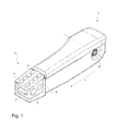
FIG. 1 is a perspective view of an armrest device;
FIG. 2A is a side view of an armrest device according to FIG. 1;
FIG. 2B is a plan view of an armrest device according to FIG. 1;
FIG. 3A is a view of second control elements;
FIG. 3B is a section in the width direction of FIG. 3A;
FIG. 4 shows possible arrangements of first control elements;
FIG. 5 shows an electronic circuit.
DETAILED DESCRIPTION
The armrest device 1 shown in FIG. 1 comprises a multiplicity of first control elements 2 which are arranged on an upper surface 4 of the armrest device 1 and in particular in terms of the longitudinal direction in a front region 11 of the armrest device 1, and two second control elements 3 which are arranged on a side surface 5 and likewise in the front region 11 of the armrest device 1. The armrest device 1 is configured such that it can be swivelled around a swivelling axis 12, wherein by means of the swivelling axis 12 the armrest device 1 can be arranged, for example, on the utility vehicle seat (not shown here). The armrest device 1 further comprises a third control element 7 which is arranged on a front surface 6 of the armrest device 1 seen in the longitudinal direction.
By means of the arrangement shown in FIG. 1, the first 2, second 3 and likewise the third control elements 7 can be easily actuated using one hand. Preferably, the present armrest device 1 is a right-hand armrest. However, it is also conceivable for the armrest device 1 shown to be a left-hand armrest. The second control elements 3 can be arranged on a side surface 5 facing the vehicle seat and/or on a side surface 5 facing away from the vehicle seat.
FIG. 2A is a side view of the armrest device 1 of FIG. 1 It can also be clearly seen here that in the present case the upper surface 4 is lowered further with respect to an arm support 13 seen in the height direction H. This assists and facilitates likewise the operation of the control elements 2, 3, 7, since the configuration of the armrest device 1 is adapted still more closely to the shape of a hand. As can be seen further, in the present case the first control elements 2 are concave in construction, so that feeling by an operator can be effected more easily.
It is further to be seen that the second control elements 3 attached on the side can be differentiated haptically. FIG. 2A thus shows inter alia a different size of the second control elements 3, while FIG. 2B, which is a plan view of the armrest device 1 of FIG. 1, shows inter alia that one of the second control elements 3′ is concave in construction and the other second control element 3″ is convex in construction, as a result of which an easy, haptic differentiation can be provided for the operator. It is therefore not necessary for the operator to have to perform a visual control in order to check which function he is just actuating.
Another embodiment variant of the second control elements 3 is shown in FIGS. 3A and 3B, wherein FIG. 3A is a perspective view and FIG. 3B is a section in the width direction B through both second control elements 3.
As can be seen from the drawings, in the present case both second control elements 3 are concave in construction, so that the risk of an accidental use can be reduced as far as possible. For the haptic differentiation in the present case it is entirely sufficient to have different sizes and optionally different raised symbols, such as a “+” and a “−” shown in the present case.
FIG. 4 shows a possible arrangement of first control elements 2 which comprises the following functions, starting from the left top to left bottom and right top to right bottom: driving mode switch, massage system, lumbar support upper balloon, side contour back cushion, seat heating, active seat climate control, lumbar support lower balloon, side contour seat cushion.
FIG. 5 shows in this context a possible electronic arrangement for controlling the vehicle functions 14 according to the invention. When an operator actuates a first control element 2, the detection device 8 detects this actuation and generates a signal which is assigned to the actuated first control element 2. This signal is transmitted to an assignment device 9, wherein a vehicle function 14 can be assigned to the actuated first control element 2 by means of the assignment device 9. By changing the underlying assignment specification, a different vehicle function 14 can also be assigned to each first control element.
A control device 10 is further provided, which is connected at least by means of a signal to the assignment device 9, the second control elements 3 and the associated actuators 15.
Preferably, the particular vehicle function 14 also comprises information on the manner in which an actuator 15 is controlled by means of the control device. This is appropriate since a lumbar support should of course be adjusted with a different adjustment speed to a massage system or a cushion contour, for example of the backrest or of the seat part.
Advantageously, the second control element 2 can be actuated continuously and/or actuated several times. A change in the vehicle function is initiated by actuating a second control element, wherein the duration and/or the frequency of the actuation of the second control element changes the vehicle function accordingly. It is thus conceivable that during a continuous actuation, that is to say, for example, an uninterrupted pressing of the second control element, this is detected and the vehicle function can be adjusted according to a predetermined or predeterminable sensitivity. In the case of interrupted pressing of the second control element, that is to say, for example, a repeated pressing of the second control element, it is conceivable that the vehicle function can be changed by a certain value on each pressing of the second control element. A combination of interrupted and uninterrupted pressing is of course also conceivable.
All the features disclosed in the application text are claimed as essential to the invention where they are novel with respect to the state of the art individually or in combination.
LIST OF REFERENCE SIGNS
  • 1 Armrest device
  • 2 First control element
  • 3 Second control element
  • 4 Upper surface
  • 5 Side surface
  • 6 Front surface
  • 7 Third control element
  • 8 Detection device
  • 9 Assignment device
  • 10 Control device
  • 11 Front region
  • 12 Swiveling axis
  • 13 Arm support surface
  • 14 Vehicle function
  • 15 Actuator
  • B Width direction
  • L Longitudinal direction
  • H Height direction

Claims (10)

The invention claimed is:
1. An armrest device for a utility vehicle seat, wherein the armrest device comprises:
a plurality of first control elements arranged on an upper surface of the armrest device, wherein a first control element of the plurality of first control elements is configured to be actuated to assign a vehicle function to the first control element and to form an actuated first control element, and
at least one second control element arranged on a side surface of the armrest device, wherein a second control element of the at least one second control element is operably connected to the actuated first control element via a plurality of signals, and the second control element of the at least one second control element is configured to be actuated to adjust the vehicle function;
a detection device that detects actuation of the first control element of the plurality of first control elements and that generates a signal of the plurality of signals which can be assigned to the actuated first control element, wherein the detection device is configured to transmit the signal generated to an assignment device, which is configured to assign a vehicle function to the actuated first control element; and
a control device, wherein, depending on the actuated first control element with the assigned vehicle function, the control device is configured to adjust the vehicle function on actuation of the second control element of the at least one second control element according to a predeterminable or predetermined plan, wherein the control device is connected via additional signals of the plurality of signals to the assignment device, the at least one second control element, and actuators for adjusting the vehicle function.
2. The armrest device according to claim 1, wherein the at least one second control element is arranged on a side surface of the armrest device which faces the utility vehicle seat.
3. The armrest device according to claim 1, wherein the at least one second control element is arranged on a side surface of the armrest device which faces away from the utility vehicle seat.
4. The armrest device according to claim 1, wherein the at least one second control element comprises two second control elements that are differentiated at least haptically from one another.
5. The armrest device according to claim 4, wherein the two second control elements are arranged on a side surface facing the utility vehicle seat and/or on a side surface facing away from the utility vehicle seat.
6. The armrest device according to claim 4, wherein haptically differentiated is at least one of a size difference and a concavity difference.
7. The armrest device according to claim 1, wherein first control elements of the plurality of first control elements each have backlighting that can be activated when each first control element of the plurality of first control elements is actuated.
8. The armrest device according to claim 1, wherein at least one third control element is arranged on a front surface of the armrest device.
9. The armrest device according to claim 1, wherein actuation of the first control element of the plurality of first control elements can be cancelled automatically after a predeterminable or predetermined period of time.
10. The armrest device according to claim 1, wherein the vehicle function is at least one of a driving mode, a massage system, a lumbar support upper balloon, a side contour back cushion, a seat heater, an active seat climate control, a lumbar support lower balloon, and a side contour seat cushion.
US15/472,487 2016-04-01 2017-03-29 Control elements in an armrest device Active US10266071B2 (en)

Applications Claiming Priority (6)

Application Number Priority Date Filing Date Title
DE102016106030 2016-04-01
DE202016101747.5U DE202016101747U1 (en) 2016-04-01 2016-04-01 Controls in an armrest device
DE202016101747U 2016-04-01
DE202016101747.5 2016-04-01
DE102016106030.5 2016-04-01
DE102016106030.5A DE102016106030B4 (en) 2016-04-01 2016-04-01 Operating elements in an armrest device and method for adjusting a vehicle function

Publications (2)

Publication Number Publication Date
US20170282762A1 US20170282762A1 (en) 2017-10-05
US10266071B2 true US10266071B2 (en) 2019-04-23

Family

ID=58410124

Family Applications (1)

Application Number Title Priority Date Filing Date
US15/472,487 Active US10266071B2 (en) 2016-04-01 2017-03-29 Control elements in an armrest device

Country Status (3)

Country Link
US (1) US10266071B2 (en)
EP (1) EP3225458B1 (en)
CN (1) CN107264354B (en)

Cited By (4)

* Cited by examiner, † Cited by third party
Publication number Priority date Publication date Assignee Title
USD890559S1 (en) 2018-04-23 2020-07-21 Gci Outdoor, Inc. Armrest
US20200376995A1 (en) * 2019-05-29 2020-12-03 Gulfstream Aerospace Corporation Seat assembly including an armrest with a lever handle and method for making the same
USD935256S1 (en) 2019-05-30 2021-11-09 Gulfstream Aerospace Corporation Armrest including a seat console
USD997618S1 (en) 2020-07-08 2023-09-05 Gci Outdoor Llc Armrest

Families Citing this family (5)

* Cited by examiner, † Cited by third party
Publication number Priority date Publication date Assignee Title
EP3225458B1 (en) * 2016-04-01 2018-12-12 Grammer Ag Control elements in an armrest device
FR3072914B1 (en) * 2017-10-27 2021-04-16 Renault Sas VEHICLE SEAT EQUIPPED WITH A CONTROL ARMREST
EP3947150A4 (en) * 2019-04-01 2022-11-30 HAECO Americas, LLC Seat system having a solenoid-actuated recline lever
DE102019213846A1 (en) * 2019-09-11 2021-03-11 Zf Friedrichshafen Ag Motor vehicle
US11958395B2 (en) * 2022-01-21 2024-04-16 Aquila Corporation Vehicle seat with embedded inflatable bladder system

Citations (36)

* Cited by examiner, † Cited by third party
Publication number Priority date Publication date Assignee Title
US5244066A (en) * 1992-10-16 1993-09-14 Caterpillar Inc. Vehicle control console having finger tip controls
US5555172A (en) * 1994-08-22 1996-09-10 Prince Corporation User interface for controlling accessories and entering data in a vehicle
US5566778A (en) * 1994-08-03 1996-10-22 Same S.P.A Control assembly for operating an agricultural tractor
US5887669A (en) * 1997-05-08 1999-03-30 Case Corporation Auxiliary hydraulic control system
US5945646A (en) * 1997-08-04 1999-08-31 Lear Automotive Dearborn, Inc. Multi-switch device for controlling vehicle subsystems
US5960903A (en) * 1997-04-25 1999-10-05 Linde Aktiengesellschaft Driver restraint device for an industrial truck
DE10037619A1 (en) 2000-08-02 2002-02-14 Daimler Chrysler Ag Arrangement of controls
US20020125988A1 (en) * 2000-12-08 2002-09-12 Chikao Nagasaka Device controller
US6476794B1 (en) * 1997-01-31 2002-11-05 Yazaki Corporation System switch
US20020171292A1 (en) * 2000-08-03 2002-11-21 Emil Dinkel Switch arrangement
EP1343113A2 (en) 2002-03-08 2003-09-10 Calsonic Kansei Corporation Input apparatus for vehicle-installed instruments
US20040164963A1 (en) * 2003-01-16 2004-08-26 Takatoshi Ono Trackball device and vehicle incorporating the same
US20050133292A1 (en) * 2003-12-19 2005-06-23 Caterpillar, Inc. Operator control assembly
US7018158B2 (en) * 2002-04-03 2006-03-28 Kabushiki Kaisha Toyota Jidoshokki Operating member and armrest for industrial vehicle
FR2889125A3 (en) 2005-07-27 2007-02-02 Renault Sas Control console for e.g. commercial vehicle, has end integrated to unit e.g. armrest, or central control, lateral opening rotating control unit around vertical axis and accessible from both sides of console, and reception cavity
US7302322B1 (en) * 2006-06-28 2007-11-27 Gm Global Technology Operations, Inc. Vehicular interface including armrest control assembly
US20070273207A1 (en) * 2005-02-11 2007-11-29 Daimlerchrysler Ag Operational Control for a Vehicle
US7373229B2 (en) * 2004-07-29 2008-05-13 Gm Global Technology Operations, Inc. Multifunction control system
US20080278442A1 (en) * 2000-08-25 2008-11-13 Toyota Jidosha Kabushiki Kaisha Control apparatus and method for input screens
US20090140993A1 (en) * 2007-11-29 2009-06-04 Daesung Electric Co., Ltd Sensation system
US20100199212A1 (en) * 2008-09-26 2010-08-05 Visteon Global Technologies, Inc. Operating Element For Display-Supported Technical Systems
US20110025488A1 (en) * 2009-07-31 2011-02-03 Honda Motor Co., Ltd. Control knob assembly, system and control method
US7965282B2 (en) * 2005-07-29 2011-06-21 Honda Motor Co., Ltd. Operation device for vehicle
US7999790B2 (en) * 2006-05-12 2011-08-16 Sikorsky Aircraft Corporation Multi-functional mission grip for a vehicle
US8039769B2 (en) * 2006-09-19 2011-10-18 Deere & Company Joystick deactivation
US20120193930A1 (en) * 2010-12-03 2012-08-02 Valtra Oy Ab Utility Vehicle Driver's Station
US8378969B2 (en) * 2008-11-07 2013-02-19 Denso Corporation Remote control apparatus for vehicle
US20140297105A1 (en) * 2011-12-29 2014-10-02 David L. Graumann Configurable control panels
US9007199B2 (en) * 2013-01-29 2015-04-14 Honda Motor Co., Ltd. Drive mode selector
US9069396B2 (en) * 2013-03-12 2015-06-30 Lightlab Imaging, Inc. Controller and user interface device, systems, and methods
US20150251573A1 (en) * 2014-03-10 2015-09-10 Ford Global Technologies, Llc Switch for selecting and adjusting seat-related functions of motor vehicle seats
US20150375865A1 (en) * 2014-06-26 2015-12-31 Itt Manufacturing Enterprises Llc Powered seat and control thereof
US20170015422A1 (en) * 2014-03-31 2017-01-19 B/E Aerospace, Inc. Electronically actuated cable release mechanism for adjustable aircraft passenger seat features and method therefor
US20170217343A1 (en) * 2016-02-03 2017-08-03 Grammer Ag Armrest device
US20170282762A1 (en) * 2016-04-01 2017-10-05 Grammer Ag Control elements in an armrest device
US20170325287A1 (en) * 2016-05-09 2017-11-09 Daechang Co., Ltd. Armrest and control method for the same

Family Cites Families (3)

* Cited by examiner, † Cited by third party
Publication number Priority date Publication date Assignee Title
CN204105374U (en) * 2014-08-19 2015-01-21 大康控股集团有限公司 A kind of multifunction seat
CN204774764U (en) * 2015-05-29 2015-11-18 苏州中航中振汽车饰件有限公司 Multi -functional massage seat chair of commercial affairs car
CN205113075U (en) * 2015-11-12 2016-03-30 西安航空学院 Multi -functional ventilation car seat

Patent Citations (39)

* Cited by examiner, † Cited by third party
Publication number Priority date Publication date Assignee Title
US5244066A (en) * 1992-10-16 1993-09-14 Caterpillar Inc. Vehicle control console having finger tip controls
US5566778A (en) * 1994-08-03 1996-10-22 Same S.P.A Control assembly for operating an agricultural tractor
US5555172A (en) * 1994-08-22 1996-09-10 Prince Corporation User interface for controlling accessories and entering data in a vehicle
US6476794B1 (en) * 1997-01-31 2002-11-05 Yazaki Corporation System switch
US5960903A (en) * 1997-04-25 1999-10-05 Linde Aktiengesellschaft Driver restraint device for an industrial truck
US5887669A (en) * 1997-05-08 1999-03-30 Case Corporation Auxiliary hydraulic control system
US5945646A (en) * 1997-08-04 1999-08-31 Lear Automotive Dearborn, Inc. Multi-switch device for controlling vehicle subsystems
DE10037619A1 (en) 2000-08-02 2002-02-14 Daimler Chrysler Ag Arrangement of controls
US20040031667A1 (en) * 2000-08-02 2004-02-19 Emil Dinkel Arrangement of operator control elements
US20020171292A1 (en) * 2000-08-03 2002-11-21 Emil Dinkel Switch arrangement
US20080278442A1 (en) * 2000-08-25 2008-11-13 Toyota Jidosha Kabushiki Kaisha Control apparatus and method for input screens
US20020125988A1 (en) * 2000-12-08 2002-09-12 Chikao Nagasaka Device controller
EP1343113A2 (en) 2002-03-08 2003-09-10 Calsonic Kansei Corporation Input apparatus for vehicle-installed instruments
US20030234764A1 (en) * 2002-03-08 2003-12-25 Calsonic Kansei Corporation Input apparatus for vehicle-installed instruments
US7018158B2 (en) * 2002-04-03 2006-03-28 Kabushiki Kaisha Toyota Jidoshokki Operating member and armrest for industrial vehicle
US20040164963A1 (en) * 2003-01-16 2004-08-26 Takatoshi Ono Trackball device and vehicle incorporating the same
US20050133292A1 (en) * 2003-12-19 2005-06-23 Caterpillar, Inc. Operator control assembly
US7373229B2 (en) * 2004-07-29 2008-05-13 Gm Global Technology Operations, Inc. Multifunction control system
US20070273207A1 (en) * 2005-02-11 2007-11-29 Daimlerchrysler Ag Operational Control for a Vehicle
FR2889125A3 (en) 2005-07-27 2007-02-02 Renault Sas Control console for e.g. commercial vehicle, has end integrated to unit e.g. armrest, or central control, lateral opening rotating control unit around vertical axis and accessible from both sides of console, and reception cavity
US7965282B2 (en) * 2005-07-29 2011-06-21 Honda Motor Co., Ltd. Operation device for vehicle
US7999790B2 (en) * 2006-05-12 2011-08-16 Sikorsky Aircraft Corporation Multi-functional mission grip for a vehicle
US7302322B1 (en) * 2006-06-28 2007-11-27 Gm Global Technology Operations, Inc. Vehicular interface including armrest control assembly
DE102007029598A1 (en) 2006-06-28 2008-02-21 GM Global Technology Operations, Inc., Detroit Vehicle interface with armrest control arrangement
US8039769B2 (en) * 2006-09-19 2011-10-18 Deere & Company Joystick deactivation
US20090140993A1 (en) * 2007-11-29 2009-06-04 Daesung Electric Co., Ltd Sensation system
US20100199212A1 (en) * 2008-09-26 2010-08-05 Visteon Global Technologies, Inc. Operating Element For Display-Supported Technical Systems
US8378969B2 (en) * 2008-11-07 2013-02-19 Denso Corporation Remote control apparatus for vehicle
US20110025488A1 (en) * 2009-07-31 2011-02-03 Honda Motor Co., Ltd. Control knob assembly, system and control method
US20120193930A1 (en) * 2010-12-03 2012-08-02 Valtra Oy Ab Utility Vehicle Driver's Station
US20140297105A1 (en) * 2011-12-29 2014-10-02 David L. Graumann Configurable control panels
US9007199B2 (en) * 2013-01-29 2015-04-14 Honda Motor Co., Ltd. Drive mode selector
US9069396B2 (en) * 2013-03-12 2015-06-30 Lightlab Imaging, Inc. Controller and user interface device, systems, and methods
US20150251573A1 (en) * 2014-03-10 2015-09-10 Ford Global Technologies, Llc Switch for selecting and adjusting seat-related functions of motor vehicle seats
US20170015422A1 (en) * 2014-03-31 2017-01-19 B/E Aerospace, Inc. Electronically actuated cable release mechanism for adjustable aircraft passenger seat features and method therefor
US20150375865A1 (en) * 2014-06-26 2015-12-31 Itt Manufacturing Enterprises Llc Powered seat and control thereof
US20170217343A1 (en) * 2016-02-03 2017-08-03 Grammer Ag Armrest device
US20170282762A1 (en) * 2016-04-01 2017-10-05 Grammer Ag Control elements in an armrest device
US20170325287A1 (en) * 2016-05-09 2017-11-09 Daechang Co., Ltd. Armrest and control method for the same

Non-Patent Citations (2)

* Cited by examiner, † Cited by third party
Title
Extended Search Report for European Patent Application No. 17162252.5, dated Aug. 2, 2017, 3 pages.
Search Report prepared by the German Patent Office dated Dec. 16, 2016, for German Patent Application No. 102016106030.5.

Cited By (5)

* Cited by examiner, † Cited by third party
Publication number Priority date Publication date Assignee Title
USD890559S1 (en) 2018-04-23 2020-07-21 Gci Outdoor, Inc. Armrest
US20200376995A1 (en) * 2019-05-29 2020-12-03 Gulfstream Aerospace Corporation Seat assembly including an armrest with a lever handle and method for making the same
US10894495B2 (en) * 2019-05-29 2021-01-19 Gulfstream Aerospace Corporation Seat assembly including an armrest with a lever handle and method for making the same
USD935256S1 (en) 2019-05-30 2021-11-09 Gulfstream Aerospace Corporation Armrest including a seat console
USD997618S1 (en) 2020-07-08 2023-09-05 Gci Outdoor Llc Armrest

Also Published As

Publication number Publication date
CN107264354B (en) 2019-11-05
EP3225458A1 (en) 2017-10-04
US20170282762A1 (en) 2017-10-05
EP3225458B1 (en) 2018-12-12
CN107264354A (en) 2017-10-20

Similar Documents

Publication Publication Date Title
US10266071B2 (en) Control elements in an armrest device
CN104302504B (en) For controlling the device of the illumination in space inside the vehicle
US10493925B2 (en) Vehicle seat comprising a display device
CN104943579B (en) System for controlling and selecting massage functions of a motor vehicle seat
US11307751B2 (en) Vehicle seat with seat operating device
WO2016070951A1 (en) Display device for a motor vehicle, method for operating a display device, and motor vehicle having a display device
US9751380B2 (en) Air vent assembly with integral air vent and control head
CN108297644B (en) Ventilation system and ventilation method for a motor vehicle
US11247585B2 (en) Vehicle seat with operating device
DE202016101747U1 (en) Controls in an armrest device
CN109476233B (en) Operating device for a motor vehicle and method for operating a motor vehicle by means of an operating device
KR101409153B1 (en) Apparatus for adjustment seat with adjustable speed
CN109017968B (en) Steering column adjustment assembly
US10882422B2 (en) Seat for vehicles with segmented backrest and movable lumbar portion
KR20190022833A (en) Method and apparatus for controlling temperature control function of vehicle seat
EP3670234A1 (en) Arrangement of an operating unit in a motor vehicle
US20240042910A1 (en) Motor vehicle
NL2026146B1 (en) Vehicle cabin unit and vehicle
JP2009262849A (en) Device and method for adjusting driving attitude of vehicle
DE19943998C2 (en) Multifunctional vehicle seat
DE102016106030A1 (en) Controls in an armrest device
KR20220135853A (en) Seat control safety apparatus of vehicle
CN110834595A (en) Interaction unit and method for controlling an adjustable element of a motor vehicle

Legal Events

Date Code Title Description
AS Assignment

Owner name: GRAMMER AG, GERMANY

Free format text: ASSIGNMENT OF ASSIGNORS INTEREST;ASSIGNORS:KLIEBER, DANIEL;HALLER, THOMAS;SCHANDERL, FLORIAN;SIGNING DATES FROM 20170419 TO 20170424;REEL/FRAME:042295/0152

STPP Information on status: patent application and granting procedure in general

Free format text: PUBLICATIONS -- ISSUE FEE PAYMENT VERIFIED

STCF Information on status: patent grant

Free format text: PATENTED CASE

AS Assignment

Owner name: GRAMMER AG, GERMANY

Free format text: CHANGE OF ADDRESS;ASSIGNOR:GRAMMER AG;REEL/FRAME:054922/0406

Effective date: 20201231

MAFP Maintenance fee payment

Free format text: PAYMENT OF MAINTENANCE FEE, 4TH YEAR, LARGE ENTITY (ORIGINAL EVENT CODE: M1551); ENTITY STATUS OF PATENT OWNER: LARGE ENTITY

Year of fee payment: 4