EP1318332A2 - Umlenkelement für eine Kugelumlaufspindel - Google Patents
Umlenkelement für eine Kugelumlaufspindel Download PDFInfo
- Publication number
- EP1318332A2 EP1318332A2 EP02258300A EP02258300A EP1318332A2 EP 1318332 A2 EP1318332 A2 EP 1318332A2 EP 02258300 A EP02258300 A EP 02258300A EP 02258300 A EP02258300 A EP 02258300A EP 1318332 A2 EP1318332 A2 EP 1318332A2
- Authority
- EP
- European Patent Office
- Prior art keywords
- leg portions
- central portion
- circulation member
- center line
- screw shaft
- Prior art date
- Legal status (The legal status is an assumption and is not a legal conclusion. Google has not performed a legal analysis and makes no representation as to the accuracy of the status listed.)
- Granted
Links
Images


Classifications
-
- F—MECHANICAL ENGINEERING; LIGHTING; HEATING; WEAPONS; BLASTING
- F16—ENGINEERING ELEMENTS AND UNITS; GENERAL MEASURES FOR PRODUCING AND MAINTAINING EFFECTIVE FUNCTIONING OF MACHINES OR INSTALLATIONS; THERMAL INSULATION IN GENERAL
- F16H—GEARING
- F16H25/00—Gearings comprising primarily only cams, cam-followers and screw-and-nut mechanisms
- F16H25/18—Gearings comprising primarily only cams, cam-followers and screw-and-nut mechanisms for conveying or interconverting oscillating or reciprocating motions
- F16H25/20—Screw mechanisms
- F16H25/22—Screw mechanisms with balls, rollers, or similar members between the co-operating parts; Elements essential to the use of such members
-
- F—MECHANICAL ENGINEERING; LIGHTING; HEATING; WEAPONS; BLASTING
- F16—ENGINEERING ELEMENTS AND UNITS; GENERAL MEASURES FOR PRODUCING AND MAINTAINING EFFECTIVE FUNCTIONING OF MACHINES OR INSTALLATIONS; THERMAL INSULATION IN GENERAL
- F16C—SHAFTS; FLEXIBLE SHAFTS; ELEMENTS OR CRANKSHAFT MECHANISMS; ROTARY BODIES OTHER THAN GEARING ELEMENTS; BEARINGS
- F16C33/00—Parts of bearings; Special methods for making bearings or parts thereof
- F16C33/30—Parts of ball or roller bearings
- F16C33/37—Loose spacing bodies
- F16C33/3706—Loose spacing bodies with concave surfaces conforming to the shape of the rolling elements, e.g. the spacing bodies are in sliding contact with the rolling elements
-
- F—MECHANICAL ENGINEERING; LIGHTING; HEATING; WEAPONS; BLASTING
- F16—ENGINEERING ELEMENTS AND UNITS; GENERAL MEASURES FOR PRODUCING AND MAINTAINING EFFECTIVE FUNCTIONING OF MACHINES OR INSTALLATIONS; THERMAL INSULATION IN GENERAL
- F16H—GEARING
- F16H25/00—Gearings comprising primarily only cams, cam-followers and screw-and-nut mechanisms
- F16H25/18—Gearings comprising primarily only cams, cam-followers and screw-and-nut mechanisms for conveying or interconverting oscillating or reciprocating motions
- F16H25/20—Screw mechanisms
- F16H25/22—Screw mechanisms with balls, rollers, or similar members between the co-operating parts; Elements essential to the use of such members
- F16H25/2204—Screw mechanisms with balls, rollers, or similar members between the co-operating parts; Elements essential to the use of such members with balls
- F16H25/2214—Screw mechanisms with balls, rollers, or similar members between the co-operating parts; Elements essential to the use of such members with balls with elements for guiding the circulating balls
-
- Y—GENERAL TAGGING OF NEW TECHNOLOGICAL DEVELOPMENTS; GENERAL TAGGING OF CROSS-SECTIONAL TECHNOLOGIES SPANNING OVER SEVERAL SECTIONS OF THE IPC; TECHNICAL SUBJECTS COVERED BY FORMER USPC CROSS-REFERENCE ART COLLECTIONS [XRACs] AND DIGESTS
- Y10—TECHNICAL SUBJECTS COVERED BY FORMER USPC
- Y10T—TECHNICAL SUBJECTS COVERED BY FORMER US CLASSIFICATION
- Y10T74/00—Machine element or mechanism
- Y10T74/19—Gearing
- Y10T74/19642—Directly cooperating gears
- Y10T74/19698—Spiral
- Y10T74/19702—Screw and nut
- Y10T74/19744—Rolling element engaging thread
- Y10T74/19749—Recirculating rolling elements
- Y10T74/19767—Return path geometry
Definitions
- the present invention relates to a circulation member or part for circulating balls of a ball screw and also relates to a ball screw using the circulation member.
- a ball screw generally comprises a screw shaft having an outer peripheral surface on which a ball rolling groove having a spiral or helical shape is formed, a nut member having an inner peripheral surface on which a ball rolling groove having a spiral or helical shape is formed, and a number of balls disposed between a loaded ball rolling passage formed by the ball rolling grooves of the screw shaft and nut member.
- the balls roll in the loaded rolling passage formed by the screw shaft and the nut member.
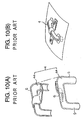
- FIG. 9 shows one example of a nut member, to which a return pipe 3 as a circulation member is mounted so as to connect one and the other end portions of a loaded rolling passage 2.
- the return pipe 3 has a portal shape having a leg portion of which end portions are provided with scooping portions for scooping the balls.
- the return pipe 3 acts to scoop, at its one end, the balls rolling on the loaded rolling passage 2, to guide them inside the return pipe 3 and then to return them to the loaded rolling passage from the other end thereof. According to such action, the balls rolling on the loaded rolling passage 2 circulate, in the endless manner, in the circulation passage composed of the loaded rolling passage 2 and the return pipe 3.
- FIG. 10 shows another example of a conventional return pipe 4.
- the return pipe 4 is divided into two parts 4a, 4a in a plane including an axial line of the pipe. These two parts 4a, 4a are produced by press-working a metal plate member by using a mold so as to provide a semi-circular cross section.
- the object of the present invention is to provide a circulation member of a ball screw capable of being easily manufactured even if a pair of leg portions provided at both end portions of a central portion of the circulation member are inclined at predetermined angles from each other with respect to the central portion thereof so as to correspond to the lead angle of a screw shaft.
- Another object of the present invention is to provide a screw shaft provided with the circulation member of the character mentioned above.
- a circulation member of a ball screw for circulating a ball rolling on a spiral ball rolling groove formed on a screw shaft comprising:
- the circulation member of the ball screw is molded by using a mold
- a mold product is generally formed by using a pair of mold halves to be opened in opposing directions. Therefore, in a case where the joining surfaces of the divided parts of the circulation member have twisted surfaces, it is difficult to mold the divided parts.
- the circulation member is divided by the first and second division surfaces, the joining surfaces of the divided parts are not twisted.
- the circulation member can be formed through the molding process.
- the circulation member can be formed from resin as well as metal. The circulation member can be thus manufactured at high performance and low cost, being advantageous.
- the center lines of the inner peripheries of the paired leg portions are inclined with respect to the center line of the inner periphery of the central portion of the circulation member so as to correspond to a lead angle of the screw shaft.
- leg portions are disposed so that the center lines of the inner peripheries thereof are each positioned in a tangential direction of the spiral ball rolling groove.
- the divided two parts have joining surfaces on which a staged portion having difference in level is formed by the first and second division surfaces.
- the circulation member can be easily manufactured.
- the staged portion may be utilized as positioning member.
- the divided parts are molded products of resin.
- the balls mainly slide but slightly roll. Because of this reason, when the ball is circulated at high speed, a large load is applied to a direction changing passage of the circulation member, resulting in generation of wearing or dust.
- the circulation member is formed as a mold product of resin, thus preventing dust or like from generating.
- a free end portions of the paired leg portions are formed with scooping portions respectively which scope balls rolling on a periphery of the screw shaft by contacting the balls, the scooping portions are molded integrally with the divided parts respectively, and each of the scooping portions is not divided by either one of the first and second division surfaces.
- the ball contacts with the scooping portion and then is scooped thereby from the loaded rolling passage into the circulation member, and for this purpose, it is required for the scooping portion to have a certain strength .
- the scooping portion when the ball is smoothly scooped, it is also required to have a high dimensional performance.
- the scooping portion is formed by divided portions, there may cause a force on the scooping portions to be opened by the contact of the balls, and in addition, there may cause a difference in level at the division (divided) surfaces.
- the scooping portions are formed integrally with the divided parts respectively, and not divided, so that the scooping portions can maintain the strength and high dimensional precision. These scooping portions can be also utilized for positioning at a time of assembling the divided parts.
- circulation member is divided into two parts only by the first and second division surfaces.
- the division surfaces having simple shapes can be provided, thus easily manufacturing the circulation member.
- each of the divided parts is formed integrally with a mount seat for mounting the circulation member to a nut member of a ball screw.
- the mount seat for mounting the circulation member to the nut member is integrally formed with each of the divided parts, the number of parts can be reduced, resulting in cost reduction and the rotation of the circulation member can be also prevented.
- the mounting angle of the circulation member with respect to the nut member becomes easily adjustable and the scooping portion can be suitable positioned.
- a circulation member of a ball screw for circulating a ball rolling on a spiral ball rolling groove formed on a screw shaft comprising:
- a fitting hole formed on the nut member for fitting the circulation member provides a slot shape on a plane. This is not avoided in its structure because a tube having a circular section is inserted, in an oblique attitude, into the nut member. Such slot is worked and formed by horizontally sliding a blade having a circular section, for example.
- the leg portion is formed so as to have a thickness different in circumferential direction at the section in the direction normal to the center line of the outer periphery of the leg portion.
- the leg portion can be formed so as to provide substantially circular outer shape in section, whereby the hole of the nut member can be formed so as to also provide substantially the circular shape in section in conformity with the outer shape of the circulation member. Therefore, the fitting hole can be easily formed on the nut member with high accuracy.
- the center lines of the inner peripheries of the paired leg portions are inclined with respect to the center line of the inner periphery of the central portion of the circulation member so as to correspond to a lead angle of the screw shaft.
- the leg portions are disposed so that the center lines of the inner peripheries thereof are each positioned in a tangential direction of the spiral ball rolling groove.
- a ball screw comprising:
- a ball screw comprising:
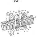
- FIG. 1 shows a ball screw to which a circulation member according to one embodiment of the present invention is mounted.
- a ball screw 8 comprises a screw shaft 9 having a spiral ball rolling groove 9a formed on its outer peripheral surface, a nut member 10 having a spiral loaded rolling groove 10a formed on its inner peripheral surface so as to oppose to the ball rolling groove 9a of the screw shaft 9 and a number of balls 11, 11, ---, 11 rolling in a passage, as loaded rolling passage, formed by the ball rolling groove 9a and the loaded rolling groove 10a.
- the nut member 10 is equipped with two, for example, return pipes 12 as circulation members or parts.
- the return pipe 12 constitutes a non-loaded return passage by connecting one and the other ends of the loaded rolling passage.
- the return pipe 12 provides approximately a portal shape having a central portion 12a and a pair of leg portions 12b, 12b formed at both ends of the central portion 12a.
- the paired leg portions 12b, 12b of the return pipe 12 are fitted into the loaded rolling passage at an interval of several pitches.
- the return pipes 12, 12 are fixed to the nut member 10 by, for example, means of bolts 13.
- the screw shaft 9 is formed, on its outer peripheral surface, with the ball rolling groove 9a through grinding or rolling working, so as to provide an approximately semi-circular cross section and a constant spiral lead.
- the nut member 10 has substantially a cylindrical shape and is provided with a flanged portion 14 at its one end surface for mounting the ball screw to a machine or like. Further, as mentioned before, on the inner peripheral surface of the nut member 10 is formed the loaded rolling groove 10, having approximately semi-circular cross section, so as to oppose to the ball rolling groove 9a of the screw shaft 9.
- the nut member 10 is also formed with a flat portion 15 by planing a portion of the upper surface of the nut member 10, and a several return pipe fitting holes into which the leg portions 12b, 12b of the return pipes 12 are formed in this flat portion 15.
- a number of spacers 16, 16, ---, 16 are interposed between the respective adjacent balls 11, 11 so as to prevent the balls from contacting or colliding each other.
- the return pipe 12 according to the present invention is of course applicable to a ball screw provided with no such spacer.
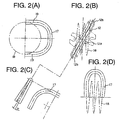
- FIG. 2 includes views showing the relationship between the non-loaded return passage 17 formed in the inner peripheral surface of the return pipe 12 and the spiral loaded rolling passage 18 formed on the screw shaft 9 of the ball screw.
- the outer configuration of the return pipe 12 is designated by two-dot chain line
- the non-loaded return passage 17 is shown with solid line
- the center line of a track of the ball in the loaded rolling passage 18 is shown with one-dot chain line.
- FIG. 2A shows a state of the screw shaft 9 viewed from its axial direction
- FIG. 2B is a plan view of the screw shaft 9 from the upper side thereof
- FIG. 2C shows a twisted state of the non-loaded return passage 17
- FIG. 2D is a side view from the side portion of the screw shaft 9.
- the balls 11 roll on the spiral loaded rolling passage 18.
- the ball change a direction in its own advancing direction, any compulsory force is not applied.
- center lines 19, 19 of the inner peripheral surfaces of the paired leg portions 12b, 12b of the return pipe 12 are positioned, as shown in FIG. 2A, in the tangential direction of the loaded rolling passage 18 and, as shown in FIGs. 2B to 2D, are inclined, with an angle ⁇ between them, in different directions from each other with the center line of the central portion 12a being the center thereof so as to correspond to the lead angle of the spiral loaded rolling passage 18.
- the center line of the leg portion 12b is positioned in the tangential direction and inclined in the direction corresponding to the lead angle of the spiral loaded rolling passage 18.
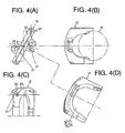
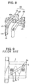
- FIG. 3 is the developed perspective view of the return pipe 12 and FIG. 4 shows details of the assembled return pipe 12 of FIG. 3, in which FIG. 4A shows a plan view of the return pipe 12, FIG. 4B is the side view of the return pipe 12 viewed from the axial direction of the screw shaft 9, FIG. 4C shows the side view of the return pipe 12 viewed from a direction normal to the axial line of the screw shaft 9, and FIG. 4D is the front view of the return pipe 12.
- the return pipe 12 is divided into two parts approximately along the axial line thereof.
- the return pipe 12 is divided by a first division surface 21 including the center line of the inner periphery of one leg portion 12b and the center line of the inner periphery of the central portion 12a and, different from this first division surface 21, a second division surface 22 including the center line of the inner periphery of the other one leg portion 12b and the center line of the inner periphery of the central portion 12a.
- first and second division surfaces 21 and 22 are flat surfaces.
- a staged portion 23 (a portion having difference in level) is formed at a position at which the first and second division surfaces 21 and 22 intersect each other on the joining surfaces of the respective divided parts 20, 20 (which may mean herein parts to be divided 20, 20).
- the staged portion 23 is formed at substantially the central portion in the axial direction of the return pipe.
- the laterally paired divided parts 20, 20 provide the quite same shape, and the paired divided parts 20, 20 are combined through, such as, thermal calking, fusing or joining (bonding) process, or by using adhesive sheet or clip as coupling means. Further, the staged portion 23 formed on the joining surface may be formed with an arcuate portion.
- the return pipe 12 is formed by means of mold, it is general to mold a mold product by using mold halves which are openable in front and rear direction. Accordingly, if the joining surfaces of the divided parts 20, 20 of the return pipe 12 have twisted shapes, it is difficult to mold the divided parts 20, 20. On the contrary, according to the embodiment of the present invention, since the return pipe 12 is divided at the first and second division surfaces 21 and 22, the joining surfaces (surfaces to be joined) of the divided parts 20, 20 will never be twisted, thus realizing the improved molding of the divided parts 20, 20.
- the return pipe 12 can be formed from resin or metal material, which results in improved performance of the return pipe 12 as well as cost merit. Moreover, it becomes also possible to form the return pipe in different shape so as to be made thick at only a required portion such as direction changing portion without making the even thickness at all the portion of the return pipe, thus being advantageous. Still furthermore, by utilizing the staged portion 23, the respective divided parts 20, 20 can be easily coupled and positioned when assembled.
- the return pipe 12 can be formed by turning one of them by 180° and assembling it with the other one part, and furthermore, the paired divided parts 20, 20 can be manufactured by using one set of mold halves, which also result in the decreasing of the initial manufacturing cost.
- the return pipe 12 is formed from a resin product.
- the resin pipe 12 may be formed of resin or metal material by using a mold.
- the metal product it is molded by thermally treating metal powder, and the metal product will provide a strength substantially identical to that of a conventional metal tube.
- wearing will be caused and, hence, chip or like may be generated.
- the balls 11, 11, --- carry out the rolling motion between the screw shaft 9 and the nut member 10, so that less wearing is caused and, hence, less chip, dust or like is generated.
- the divided part 20 has the first division surface 21 and the second division surface 22, and the staged portion 23 is formed at the central portion in the axial direction thereof.
- This staged portion 23 is formed on each side of the non-loaded return passage 17.
- Scooping portions 25, 25 are molded to the front (free) end portions of the paired leg portions 12b, 12b, respectively, so as to contact and scoop the balls 11 rolling around the screw shaft 9 into the return pipe 12.
- These scooping portions 25, 25 are integrally formed on the respective divided parts 20, 20 but are not divided by the first or second division surface 21 or 22.
- the first and second division surfaces 21 and 22 brake off on the way of the leg portions 12b, 12b respectively, and intersect leg portion division surfaces 26, 26 normal to the center lines of the inner peripheries of the leg portions 12b, 12b.
- the scooping portion 25 is thus formed in one of the divided leg portion 12b.
- the leg portion 12b in which the scooping portion 25 is not formed is cut off by the same plane as that of the leg portion division surface 26.
- the scooping portions 25, 25 are formed in the paired leg portions 12b, 12b of the return pipe 12, respectively.
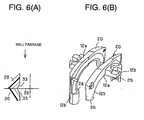
- FIG. 6 shows the detail of the divided two parts 20, 20 of the return pipe 12 at a portion near the leg portion division surface 26 (i.e., joining surface) , in which FIG. 6A shows the sectional view along the center line of the leg portion 12b of the divided part 20 and FIG . 6B is a perspective view thereof .
- a difference in level staged portion
- chamfering may be effected to one or both of the joining surfaces 33, 33 of the two divided parts 20, 20.
- the scooping portion 25 contacts the ball 11 to scoop the ball 11 from the loaded rolling passage 18 into the return pipe 12. For this purpose, it is required for the scooping portion 25 to have a certain strength. Moreover, in order to smoothly scoop the ball 11, it is also required for the scooping portion 25 to have a high precision in dimension. In such requirement, if the scooping portion 12b is formed in a divided manner to the divided two leg portions 12b, there is a fear of causing a force to the scooping portion 25 to be opened by the contact of the ball 11 to the divided scooping portion 25, and moreover, the scooping portion 25 may itself provide the difference in level at the divided portions.
- the scooping portion 25 is integrally formed in each of the divided parts 20, 20 and is not itself divided, so that the scooping portion 25 thus formed can provide high strength and high dimensional precision. Moreover, such scooping portion 25 may be utilized as a positioning member at the time of assembling the respective divided parts 20, 20 into the return pipe 12.
- the scooping portion 25 of the described embodiment has a shape such that a cut end (section) provides a width gradually narrowed towards the inward of the return pipe 12, and the ball 11 can be scooped through the contact of both side portions of this cut end portion to the ball 11.
- the scooping portion 25 is formed, at its root portion, with a tongue shaped projection 27, which acts to guide the spacer 16 disposed between adjacent two balls 11, 11.
- the scooping portion 25 since the scooping portion 25 has a complicated shape or configuration, it is difficult to machine work the scooping portion 25. And, it is difficult to form the scooping portion 25 by using only a laterally divided mold halves .
- the scooping portion 25 is molded by using a slide mold, not shown, enabling scooping portion 25 to slide in the axial direction of the leg portion 12b. More especially, the slide mold is inserted into a lateral pair of molds at the time of molding process, and next, under the inserted state, the scooping portion 25 is formed in the divided part 20. When the mold halves are separated, the slide mold is slid in the opposing direction to thereby take out the divided part 20.
- the slide mold not only the complicated scooping portion, but also the inner periphery of the leg portion can be molded or formed.
- the scooping portion 25 is not formed with any lip portion for scooping the ball 11 in contact thereto, it is of course possible to form a certain projection or like portion, such as lip, contacting and scooping the ball.
- Each of the divided parts 20, 20 of the return pipe 12 is integrally formed with a mount seat 29 (FIG. 5).
- a tubular return pipe of conventional structure formed through a bending working or like working it is necessary to separately dispose a pressing part for pressing the return pipe to the nut member.
- the mount seat 29 for mounting the return pipe 12 to the nut member 10 is integrally formed with each divided part 20, parts or members to be required for the ball screw can be significantly reduced, thus being advantageous especially in cost.
- the rotation of the return pipe 12 can be also prevented.
- the return pipe 12 will be mounted to the nut member 10 with easily adjustable mount angle, and the scooping portion 25 can be hence suitably positioned in operation.
- a positioning pin 31 is integrally formed on the first division surface 21 of each of the divided parts 20 of the return pipe 12 for mutually positioning the paired divided parts 20, 20, and on the other hand, a hole 32 to be fitted with the positioning pin 31 is formed on the second division surface 22 of each divided part 20.
- the positioning pin 31 and the fitting hole 32 serve to position the divided parts 20, 20 in association with the staged portion 23 and the scooping portion 25 as mentioned above.
- FIG. 7 shows the return pipe 12 as the circulation member and a mount (mounting) hole 33 formed in the nut member 10, in which FIG. 7A shows a conventional tube-type return pipe and FIG. 7B shows the return pipe 12 according to the present invention.
- the leg portion 12b of the return pipe 12 is inclined with respect to the central portion 12a thereof, and the leg portion 12b has the even thickness in its section .
- the mount hole 33 for mounting the return pipe to the nut member 10 provides a slot shape on a plane. Such fact is not avoidable in its structure because the tube having a circular section is inserted into the nut member 10 in an oblique state.
- This mount hole 33 in slot shape is, for example, formed by horizontally sliding a blade having a circular section.
- hole forming method there is a fear of being inclined by a resisting force to the blade at the time of horizontally moving the blade, which results in deterioration in working accuracy.
- a gap may be formed between the mount hole 33 and the return pipe 12 and any foreign substance may be invaded into such gap.
- the inner periphery of the leg portion 12b of the return pipe 12 is inclined with respect to the inner periphery of the central portion 12a thereof, but the outer periphery of the leg portion 12b is not inclined with respect to the outer periphery of the central portion 12a. That is, the center lines of the paired leg portions 12b, 12b of the return pipe 12 are parallel to each other and the thickness of the leg portion 12b differs in its circumferential direction at a cross section in the direction normal to the center line of the outer periphery of the leg portion 12b. Thus , the outer peripheries of the paired leg portions 12b, 12b have each substantially circular cross section.
- the thickness of the leg portion 12b differs in the circumferential direction on the cross section in the direction normal to the center line of the outer periphery of the leg portion 12b, irrespective of the inner peripheral shape of the leg portion 12b, the outer periphery of the leg portion 12b can be made to provide, for example, substantially circular section, whereby the mount hole 33 formed in the nut member 10 can accord with the outer shape of the return pipe 12 , for example, so as to provide substantially circular section.
- the mount hole 33 can be easily formed in the nut member 10 with high precision.
- FIG. 8 represents another example of a circulation member for the ball screw.
- a circulation member 43 as return pipe comprises a pair of divided parts 40, 40 which are divided only by first and second division surfaces 41 and 42.
- a portion having difference in level as a staged portion 45 is formed at a central portion 43a of the circulation member 43 by the first and second division surfaces 41 and 42.
- a scooping portion 44 formed in the front end of each of the paired leg portions 43b, 43b is also divided into two parts by the first and second division surfaces 41 and 42.
- the scooping portions 44 are formed in a pair of leg portions 43b, 43b of the respective divided parts 40, 40 so as to provide each substantially semi-circular section, and the scooping portion 44 is itself formed by joining, i.e., assembling, the two divided parts 40, 40 for forming the circulation member 43 as the return pipe.
- a third division surface different from the first division surface, the second division surface and the leg portion division surface may be additionally formed on the joining surfaces of the respective divided parts of the return pipe.
- the staged portion different in level may be formed at a portion other than the central portion of the return pipe.
- the return pipe may be formed as a metal product as well as resin product.
- the ball screw of the described invention may be applied as a ball screw assembled to a driving unit.
Priority Applications (1)
| Application Number | Priority Date | Filing Date | Title |
|---|---|---|---|
| EP05011823A EP1577585B1 (de) | 2001-12-05 | 2002-12-02 | Umlenkelement für eine Kugelumlaufspindel |
Applications Claiming Priority (4)
| Application Number | Priority Date | Filing Date | Title |
|---|---|---|---|
| JP2001372047 | 2001-12-05 | ||
| JP2001372047 | 2001-12-05 | ||
| JP2002324425 | 2002-11-07 | ||
| JP2002324425A JP3993504B2 (ja) | 2001-12-05 | 2002-11-07 | ボールねじの循環部品及びボールねじ |
Related Child Applications (1)
| Application Number | Title | Priority Date | Filing Date |
|---|---|---|---|
| EP05011823A Division EP1577585B1 (de) | 2001-12-05 | 2002-12-02 | Umlenkelement für eine Kugelumlaufspindel |
Publications (3)
| Publication Number | Publication Date |
|---|---|
| EP1318332A2 true EP1318332A2 (de) | 2003-06-11 |
| EP1318332A3 EP1318332A3 (de) | 2004-03-24 |
| EP1318332B1 EP1318332B1 (de) | 2006-02-15 |
Family
ID=26624896
Family Applications (2)
| Application Number | Title | Priority Date | Filing Date |
|---|---|---|---|
| EP05011823A Expired - Lifetime EP1577585B1 (de) | 2001-12-05 | 2002-12-02 | Umlenkelement für eine Kugelumlaufspindel |
| EP02258300A Expired - Lifetime EP1318332B1 (de) | 2001-12-05 | 2002-12-02 | Umlenkelement für eine Kugelumlaufspindel |
Family Applications Before (1)
| Application Number | Title | Priority Date | Filing Date |
|---|---|---|---|
| EP05011823A Expired - Lifetime EP1577585B1 (de) | 2001-12-05 | 2002-12-02 | Umlenkelement für eine Kugelumlaufspindel |
Country Status (7)
| Country | Link |
|---|---|
| US (1) | US7040189B2 (de) |
| EP (2) | EP1577585B1 (de) |
| JP (1) | JP3993504B2 (de) |
| KR (2) | KR100912568B1 (de) |
| CN (2) | CN100350174C (de) |
| AT (2) | ATE353123T1 (de) |
| DE (2) | DE60209194T2 (de) |
Cited By (3)
| Publication number | Priority date | Publication date | Assignee | Title |
|---|---|---|---|---|
| EP1375938A1 (de) * | 2002-06-25 | 2004-01-02 | THK Co., Ltd. | Linearlager mit einer Kugelumlenkvorrichtung oder Kugelgewindetrieb mit einer Umlaufvorrichtung |
| EP1681493A1 (de) * | 2003-10-30 | 2006-07-19 | NSK Ltd. | Kugelspindelvorrichtung |
| EP2784351A1 (de) * | 2013-03-29 | 2014-10-01 | Jtekt Corporation | Kugelrückführung für Kugelumlaufspindel |
Families Citing this family (36)
| Publication number | Priority date | Publication date | Assignee | Title |
|---|---|---|---|---|
| DE10242297A1 (de) * | 2002-09-12 | 2004-03-18 | Ina-Schaeffler Kg | Kugelgewindetrieb |
| JP3097525U (ja) * | 2003-04-21 | 2004-01-29 | Thk株式会社 | 転動体ねじ装置 |
| CN100553869C (zh) | 2003-09-10 | 2009-10-28 | 日本精工株式会社 | 滚珠丝杠装置 |
| JP2005083519A (ja) * | 2003-09-10 | 2005-03-31 | Nsk Ltd | ボールねじ装置 |
| JP2005155720A (ja) * | 2003-11-21 | 2005-06-16 | Thk Co Ltd | ねじ装置及びその製造方法 |
| JP2005240878A (ja) * | 2004-02-25 | 2005-09-08 | Nsk Ltd | ボールねじ |
| DE102004023354A1 (de) * | 2004-05-12 | 2005-12-08 | Ina-Schaeffler Kg | Kugelgewindetrieb |
| DE102004023353A1 (de) * | 2004-05-12 | 2005-12-08 | Ina-Schaeffler Kg | Kugelgewindetrieb |
| JP2006046530A (ja) | 2004-08-05 | 2006-02-16 | Nsk Ltd | ボールねじ装置 |
| EP1624228B1 (de) * | 2004-08-06 | 2011-10-12 | NSK Ltd. | Kugelumlaufmechanismus und Kugelgewindetrieb |
| JP4525233B2 (ja) * | 2004-08-06 | 2010-08-18 | 日本精工株式会社 | ボール循環部材およびボールねじ |
| WO2006068202A1 (ja) * | 2004-12-22 | 2006-06-29 | Nsk Ltd. | ボールねじ装置 |
| US20060169079A1 (en) * | 2005-02-02 | 2006-08-03 | Mao-Tu Lee | Muffling structure of high-speed ball screw |
| KR100654025B1 (ko) * | 2005-02-24 | 2006-12-05 | 히순-첸 리 | 고속 볼스크류의 머플링 장치 |
| JPWO2006104015A1 (ja) * | 2005-03-25 | 2008-09-04 | 日本精工株式会社 | ボールねじ |
| JP4875888B2 (ja) * | 2005-11-30 | 2012-02-15 | Thk株式会社 | 転動体ねじ装置及び転動体ねじ装置の循環部材の製造方法 |
| JP4657936B2 (ja) * | 2006-01-25 | 2011-03-23 | Thk株式会社 | ボールねじ |
| CN101382188B (zh) * | 2007-09-03 | 2010-07-28 | 上银科技股份有限公司 | 一种外循环式滚珠螺杆 |
| US7934438B2 (en) * | 2007-10-31 | 2011-05-03 | Hiwin Technologies Corp. | Ball screw device having circulating device background of the invention |
| CN101655144B (zh) * | 2008-08-19 | 2012-02-15 | 全球滚珠科技股份有限公司 | 滚珠螺杆装置 |
| TWI385325B (zh) * | 2008-11-14 | 2013-02-11 | Hiwin Tech Corp | 滾珠螺桿 |
| CN101749391B (zh) * | 2008-12-13 | 2012-05-30 | 上银科技股份有限公司 | 外循环滚珠螺杆装置 |
| US20110303036A1 (en) * | 2009-01-06 | 2011-12-15 | Hiwin Technologies Corp. | Ball return device for ball screw device |
| DE102009009522A1 (de) * | 2009-02-18 | 2010-08-19 | Schaeffler Technologies Gmbh & Co. Kg | Umlenkkörper für einen Kugelgewindetrieb |
| DE102010050175A1 (de) * | 2010-10-30 | 2012-05-03 | Volkswagen Ag | Kugelgewindemutter |
| DE102011017262A1 (de) * | 2011-04-15 | 2012-10-18 | Volkswagen Aktiengesellschaft | Kugelgewindetrieb und Kugelrückführungspfadteilstück |
| JP5856506B2 (ja) * | 2012-03-07 | 2016-02-09 | Thk株式会社 | モータ制御装置、及び磁極位置検出方法 |
| DE102013226712A1 (de) | 2013-12-19 | 2015-06-25 | Volkswagen Aktiengesellschaft | Kugelrückführungsvorrichtung für eine Kugelgewindemutter, Klammer zur Fixierung einer Kugelrückführungsvorrichtung, Kugelgewindemutter sowie Anordnung einer Kugelrückführungsvorrichtung an einer Kugelgewindemutter |
| CN107107949A (zh) * | 2014-12-03 | 2017-08-29 | Trw汽车美国有限责任公司 | 用于车辆转向器的齿条滚珠螺母组件及其相关部件 |
| DE102016007542A1 (de) * | 2016-06-22 | 2017-12-28 | Thyssenkrupp Ag | Kugelgewindetrieb einer elektromechanischen Servolenkung mit Umlenkkörper für eine Kugelrückführung |
| TWI606197B (zh) * | 2016-12-23 | 2017-11-21 | Hiwin Tech Corp | External circulation ball screw |
| CN108386506A (zh) | 2017-01-24 | 2018-08-10 | 上银科技股份有限公司 | 外循环式滚珠螺杆 |
| CN110375045A (zh) * | 2018-04-13 | 2019-10-25 | 银鼎精密元件(上海)有限公司 | 二件式回流管及滚珠螺杆结构 |
| CN110375046B (zh) * | 2018-04-13 | 2022-07-19 | 银鼎精密元件(上海)有限公司 | 滚珠螺杆结构 |
| CN114060486B (zh) * | 2020-08-06 | 2024-04-16 | 银泰科技股份有限公司 | 外循环滚珠螺杆及其回流管结构 |
| CN114370484A (zh) * | 2022-03-22 | 2022-04-19 | 天津德科智控股份有限公司 | 一种组合式返向器及滚珠丝杠螺母装置 |
Family Cites Families (22)
| Publication number | Priority date | Publication date | Assignee | Title |
|---|---|---|---|---|
| US2851897A (en) * | 1957-03-05 | 1958-09-16 | Alfred P M Cochrane | Screw and nut assembly |
| US3143896A (en) * | 1962-03-20 | 1964-08-11 | Gen Motors Corp | Ball nut return guide |
| US3145580A (en) * | 1963-01-29 | 1964-08-25 | Gen Motors Corp | Ball bearing nut and screw assembly |
| FR2230238A5 (de) * | 1973-05-16 | 1974-12-13 | Tech Integrale | |
| DE2809647C2 (de) * | 1978-03-06 | 1979-06-28 | Zahnradfabrik Friedrichshafen Ag, 7990 Friedrichshafen | Kugelumlaufschraubgetriebe |
| JPS6037489Y2 (ja) * | 1981-05-15 | 1985-11-08 | 日本精工株式会社 | ボ−ルねじのボ−ルチユ−ブ |
| US4750378A (en) * | 1986-11-13 | 1988-06-14 | Sheppard Peter H | Ball screw mechanism |
| JPH0527729Y2 (de) * | 1987-02-20 | 1993-07-15 | ||
| IT1219011B (it) * | 1988-02-11 | 1990-04-24 | Roltra Spa | Accoppiamento vite madrevite a circolazione di sfere |
| US4953419A (en) * | 1989-09-19 | 1990-09-04 | Dana Corporation | Ball screw return system |
| US5063809A (en) * | 1990-10-15 | 1991-11-12 | Dana Corporation | Return tube arrangement for ball screw assembly |
| JP2545265Y2 (ja) * | 1991-03-28 | 1997-08-25 | 日本精工株式会社 | ボールねじのボール循環路 |
| JPH06201013A (ja) * | 1992-12-28 | 1994-07-19 | Koyo Seiko Co Ltd | ボールねじ |
| US5555770A (en) | 1994-10-12 | 1996-09-17 | Thomson Saginaw Ball Screw Company, Inc. | Ball screw and nut system |
| CN1107178C (zh) * | 1996-06-21 | 2003-04-30 | Thk株式会社 | 滚珠丝杠装置 |
| JP3726394B2 (ja) * | 1997-01-14 | 2005-12-14 | 日本精工株式会社 | ボールねじのボール循環チューブ |
| JPH10213203A (ja) * | 1997-01-31 | 1998-08-11 | Tsubakimoto Chain Co | ボールねじ用リターンチューブ |
| KR100373570B1 (ko) * | 1997-07-31 | 2003-02-26 | 티에치케이 가부시끼가이샤 | 볼나사장치 |
| JP4294115B2 (ja) * | 1998-03-25 | 2009-07-08 | Thk株式会社 | ボールねじ装置 |
| JP4220018B2 (ja) * | 1998-06-26 | 2009-02-04 | Thk株式会社 | ボールねじ |
| JP4256003B2 (ja) * | 1999-01-29 | 2009-04-22 | Thk株式会社 | 転動体保持スペーサー及びこれを用いた直線運動装置 |
| US20050005436A1 (en) * | 2003-07-09 | 2005-01-13 | Jung-Chien Chang | Method for preparing thin integrated circuits with multiple circuit layers |
-
2002
- 2002-11-07 JP JP2002324425A patent/JP3993504B2/ja not_active Expired - Lifetime
- 2002-12-02 AT AT05011823T patent/ATE353123T1/de active
- 2002-12-02 EP EP05011823A patent/EP1577585B1/de not_active Expired - Lifetime
- 2002-12-02 AT AT02258300T patent/ATE317952T1/de active
- 2002-12-02 DE DE60209194T patent/DE60209194T2/de not_active Expired - Lifetime
- 2002-12-02 DE DE60217979T patent/DE60217979T2/de not_active Expired - Lifetime
- 2002-12-02 EP EP02258300A patent/EP1318332B1/de not_active Expired - Lifetime
- 2002-12-04 KR KR1020020076463A patent/KR100912568B1/ko active IP Right Grant
- 2002-12-04 US US10/309,341 patent/US7040189B2/en not_active Expired - Lifetime
- 2002-12-05 CN CNB021559317A patent/CN100350174C/zh not_active Expired - Lifetime
- 2002-12-05 CN CN2007101487772A patent/CN101118003B/zh not_active Expired - Lifetime
-
2009
- 2009-06-03 KR KR1020090048832A patent/KR100966210B1/ko active IP Right Grant
Non-Patent Citations (1)
| Title |
|---|
| None |
Cited By (6)
| Publication number | Priority date | Publication date | Assignee | Title |
|---|---|---|---|---|
| EP1375938A1 (de) * | 2002-06-25 | 2004-01-02 | THK Co., Ltd. | Linearlager mit einer Kugelumlenkvorrichtung oder Kugelgewindetrieb mit einer Umlaufvorrichtung |
| US6874939B2 (en) | 2002-06-25 | 2005-04-05 | Thk Co., Ltd. | Circulation member, motion guide device provided with circulation member and ball screw provided with circulation member |
| EP1681493A1 (de) * | 2003-10-30 | 2006-07-19 | NSK Ltd. | Kugelspindelvorrichtung |
| EP1681493A4 (de) * | 2003-10-30 | 2009-08-26 | Nsk Ltd | Kugelspindelvorrichtung |
| EP2784351A1 (de) * | 2013-03-29 | 2014-10-01 | Jtekt Corporation | Kugelrückführung für Kugelumlaufspindel |
| US9377092B2 (en) | 2013-03-29 | 2016-06-28 | Jtekt Corporation | Ball screw deflector |
Also Published As
| Publication number | Publication date |
|---|---|
| DE60217979D1 (de) | 2007-03-22 |
| KR20030046313A (ko) | 2003-06-12 |
| DE60209194D1 (de) | 2006-04-20 |
| KR100966210B1 (ko) | 2010-06-25 |
| KR100912568B1 (ko) | 2009-08-19 |
| ATE317952T1 (de) | 2006-03-15 |
| CN1423071A (zh) | 2003-06-11 |
| EP1577585A1 (de) | 2005-09-21 |
| DE60217979T2 (de) | 2007-10-18 |
| KR20090065501A (ko) | 2009-06-22 |
| EP1318332B1 (de) | 2006-02-15 |
| CN101118003B (zh) | 2013-07-17 |
| EP1318332A3 (de) | 2004-03-24 |
| DE60209194T2 (de) | 2006-08-10 |
| CN101118003A (zh) | 2008-02-06 |
| ATE353123T1 (de) | 2007-02-15 |
| JP2003232421A (ja) | 2003-08-22 |
| JP3993504B2 (ja) | 2007-10-17 |
| US7040189B2 (en) | 2006-05-09 |
| CN100350174C (zh) | 2007-11-21 |
| EP1577585B1 (de) | 2007-01-31 |
| US20030123951A1 (en) | 2003-07-03 |
Similar Documents
| Publication | Publication Date | Title |
|---|---|---|
| US7040189B2 (en) | Circulation member of ball screw and ball screw using same | |
| US5491997A (en) | Apparatus and method for forming a heat exchanger inner fin having cross-flow passages | |
| JP2007255435A (ja) | 転動体ねじ装置及び転動体ねじ装置の製造方法 | |
| JP3964008B2 (ja) | チューブ式ボールねじ装置 | |
| JP2008202672A (ja) | ボールねじ及びその製造方法 | |
| US6813969B2 (en) | Rocker return liner for ball nut | |
| JP4875888B2 (ja) | 転動体ねじ装置及び転動体ねじ装置の循環部材の製造方法 | |
| JP3609731B2 (ja) | ボール連結体 | |
| US20050016308A1 (en) | Tube guide for ball screw, ball screw and method for manufacturing thereof | |
| JP3150527U (ja) | 転動体ねじ装置 | |
| WO2016204023A1 (ja) | ボールねじ用ボール循環チューブ及びボールねじ並びにボールねじの製造方法 | |
| JPH1151145A (ja) | 側蓋式ボールねじ装置 | |
| JP4777934B2 (ja) | ボールねじの循環部品及びボールねじ | |
| WO2024075799A1 (ja) | ボールねじ | |
| JPH0635719U (ja) | ボールねじ | |
| JP2023167944A (ja) | ボールねじ装置 | |
| JP2006038216A (ja) | ボールねじ装置 | |
| JP2007100935A (ja) | ボールねじ装置 | |
| JP2003343683A (ja) | 直動装置 | |
| JP2003113836A (ja) | ボールリニアガイド及びボールリニアガイドの製造方法 | |
| JP4405841B2 (ja) | 異なるボールスクリューに共用される循環こま | |
| JPH11210859A (ja) | ボールねじの回帰経路システム | |
| JP2003194178A (ja) | ボールねじ | |
| JP2000266050A (ja) | 直線摺動用ベアリング | |
| JP2003194175A (ja) | ボールねじ |
Legal Events
| Date | Code | Title | Description |
|---|---|---|---|
| PUAI | Public reference made under article 153(3) epc to a published international application that has entered the european phase |
Free format text: ORIGINAL CODE: 0009012 |
|
| AK | Designated contracting states |
Designated state(s): AT BE BG CH CY CZ DE DK EE ES FI FR GB GR IE IT LI LU MC NL PT SE SI SK TR |
|
| AX | Request for extension of the european patent |
Extension state: AL LT LV MK RO |
|
| RIN1 | Information on inventor provided before grant (corrected) |
Inventor name: SHIRAI, TAKEKI,C/O THK CO., LTD. Inventor name: KADONO, TOSHIAKI,C/O THK CO., LTD. Inventor name: NIWA, HIROSHI,C/O THK CO., LTD. Inventor name: SHOJI, HIRONORI,C/O THK CO., LTD. Inventor name: MICHIOKA, HIDEKAZU,C/O THK CO., LTD. Inventor name: IIDA, KATSUYA,C/O THK CO., LTD. Inventor name: ABE, YASUYUKI,C/O THK CO., LTD. |
|
| PUAL | Search report despatched |
Free format text: ORIGINAL CODE: 0009013 |
|
| AK | Designated contracting states |
Kind code of ref document: A3 Designated state(s): AT BE BG CH CY CZ DE DK EE ES FI FR GB GR IE IT LI LU MC NL PT SE SI SK TR |
|
| AX | Request for extension of the european patent |
Extension state: AL LT LV MK RO |
|
| 17P | Request for examination filed |
Effective date: 20040916 |
|
| AKX | Designation fees paid |
Designated state(s): AT BE BG CH CY CZ DE DK EE ES FI FR GB GR IE IT LI LU MC NL PT SE SI SK TR |
|
| 17Q | First examination report despatched |
Effective date: 20050202 |
|
| GRAP | Despatch of communication of intention to grant a patent |
Free format text: ORIGINAL CODE: EPIDOSNIGR1 |
|
| GRAS | Grant fee paid |
Free format text: ORIGINAL CODE: EPIDOSNIGR3 |
|
| GRAA | (expected) grant |
Free format text: ORIGINAL CODE: 0009210 |
|
| RIN1 | Information on inventor provided before grant (corrected) |
Inventor name: SHIRAI, TAKEKI,C/O THK CO., LTD. Inventor name: NIWA, HIROSHI,C/O THK CO., LTD. Inventor name: ABE, YASUYUKI,C/O THK CO., LTD. Inventor name: IIDA, KATSUYA,C/O THK CO., LTD. Inventor name: MICHIOKA, HIDEKAZU,C/O THK CO., LTD. Inventor name: SHOJI, HIRONORI,C/O THK CO., LTD. Inventor name: KADUNO, TOSHIAKI,C/O THK CO., LTD. |
|
| AK | Designated contracting states |
Kind code of ref document: B1 Designated state(s): AT BE BG CH CY CZ DE DK EE ES FI FR GB GR IE IT LI LU MC NL PT SE SI SK TR |
|
| PG25 | Lapsed in a contracting state [announced via postgrant information from national office to epo] |
Ref country code: SI Free format text: LAPSE BECAUSE OF FAILURE TO SUBMIT A TRANSLATION OF THE DESCRIPTION OR TO PAY THE FEE WITHIN THE PRESCRIBED TIME-LIMIT Effective date: 20060215 Ref country code: CH Free format text: LAPSE BECAUSE OF FAILURE TO SUBMIT A TRANSLATION OF THE DESCRIPTION OR TO PAY THE FEE WITHIN THE PRESCRIBED TIME-LIMIT Effective date: 20060215 Ref country code: NL Free format text: LAPSE BECAUSE OF FAILURE TO SUBMIT A TRANSLATION OF THE DESCRIPTION OR TO PAY THE FEE WITHIN THE PRESCRIBED TIME-LIMIT Effective date: 20060215 Ref country code: SK Free format text: LAPSE BECAUSE OF FAILURE TO SUBMIT A TRANSLATION OF THE DESCRIPTION OR TO PAY THE FEE WITHIN THE PRESCRIBED TIME-LIMIT Effective date: 20060215 Ref country code: BE Free format text: LAPSE BECAUSE OF FAILURE TO SUBMIT A TRANSLATION OF THE DESCRIPTION OR TO PAY THE FEE WITHIN THE PRESCRIBED TIME-LIMIT Effective date: 20060215 Ref country code: FI Free format text: LAPSE BECAUSE OF FAILURE TO SUBMIT A TRANSLATION OF THE DESCRIPTION OR TO PAY THE FEE WITHIN THE PRESCRIBED TIME-LIMIT Effective date: 20060215 Ref country code: LI Free format text: LAPSE BECAUSE OF FAILURE TO SUBMIT A TRANSLATION OF THE DESCRIPTION OR TO PAY THE FEE WITHIN THE PRESCRIBED TIME-LIMIT Effective date: 20060215 |
|
| REG | Reference to a national code |
Ref country code: GB Ref legal event code: FG4D Ref country code: CH Ref legal event code: EP |
|
| REG | Reference to a national code |
Ref country code: IE Ref legal event code: FG4D |
|
| REF | Corresponds to: |
Ref document number: 60209194 Country of ref document: DE Date of ref document: 20060420 Kind code of ref document: P |
|
| PG25 | Lapsed in a contracting state [announced via postgrant information from national office to epo] |
Ref country code: BG Free format text: LAPSE BECAUSE OF FAILURE TO SUBMIT A TRANSLATION OF THE DESCRIPTION OR TO PAY THE FEE WITHIN THE PRESCRIBED TIME-LIMIT Effective date: 20060515 Ref country code: SE Free format text: LAPSE BECAUSE OF FAILURE TO SUBMIT A TRANSLATION OF THE DESCRIPTION OR TO PAY THE FEE WITHIN THE PRESCRIBED TIME-LIMIT Effective date: 20060515 Ref country code: DK Free format text: LAPSE BECAUSE OF FAILURE TO SUBMIT A TRANSLATION OF THE DESCRIPTION OR TO PAY THE FEE WITHIN THE PRESCRIBED TIME-LIMIT Effective date: 20060515 |
|
| PG25 | Lapsed in a contracting state [announced via postgrant information from national office to epo] |
Ref country code: ES Free format text: LAPSE BECAUSE OF FAILURE TO SUBMIT A TRANSLATION OF THE DESCRIPTION OR TO PAY THE FEE WITHIN THE PRESCRIBED TIME-LIMIT Effective date: 20060526 |
|
| PG25 | Lapsed in a contracting state [announced via postgrant information from national office to epo] |
Ref country code: PT Free format text: LAPSE BECAUSE OF FAILURE TO SUBMIT A TRANSLATION OF THE DESCRIPTION OR TO PAY THE FEE WITHIN THE PRESCRIBED TIME-LIMIT Effective date: 20060717 |
|
| NLV1 | Nl: lapsed or annulled due to failure to fulfill the requirements of art. 29p and 29m of the patents act | ||
| REG | Reference to a national code |
Ref country code: CH Ref legal event code: PL |
|
| ET | Fr: translation filed | ||
| PG25 | Lapsed in a contracting state [announced via postgrant information from national office to epo] |
Ref country code: IE Free format text: LAPSE BECAUSE OF NON-PAYMENT OF DUE FEES Effective date: 20061204 |
|
| PLBE | No opposition filed within time limit |
Free format text: ORIGINAL CODE: 0009261 |
|
| STAA | Information on the status of an ep patent application or granted ep patent |
Free format text: STATUS: NO OPPOSITION FILED WITHIN TIME LIMIT |
|
| PG25 | Lapsed in a contracting state [announced via postgrant information from national office to epo] |
Ref country code: MC Free format text: LAPSE BECAUSE OF NON-PAYMENT OF DUE FEES Effective date: 20061231 |
|
| 26N | No opposition filed |
Effective date: 20061116 |
|
| GBPC | Gb: european patent ceased through non-payment of renewal fee |
Effective date: 20061202 |
|
| PG25 | Lapsed in a contracting state [announced via postgrant information from national office to epo] |
Ref country code: GB Free format text: LAPSE BECAUSE OF NON-PAYMENT OF DUE FEES Effective date: 20061202 |
|
| PG25 | Lapsed in a contracting state [announced via postgrant information from national office to epo] |
Ref country code: GR Free format text: LAPSE BECAUSE OF FAILURE TO SUBMIT A TRANSLATION OF THE DESCRIPTION OR TO PAY THE FEE WITHIN THE PRESCRIBED TIME-LIMIT Effective date: 20060516 Ref country code: CZ Free format text: LAPSE BECAUSE OF FAILURE TO SUBMIT A TRANSLATION OF THE DESCRIPTION OR TO PAY THE FEE WITHIN THE PRESCRIBED TIME-LIMIT Effective date: 20060215 |
|
| PG25 | Lapsed in a contracting state [announced via postgrant information from national office to epo] |
Ref country code: EE Free format text: LAPSE BECAUSE OF FAILURE TO SUBMIT A TRANSLATION OF THE DESCRIPTION OR TO PAY THE FEE WITHIN THE PRESCRIBED TIME-LIMIT Effective date: 20060215 |
|
| PG25 | Lapsed in a contracting state [announced via postgrant information from national office to epo] |
Ref country code: TR Free format text: LAPSE BECAUSE OF FAILURE TO SUBMIT A TRANSLATION OF THE DESCRIPTION OR TO PAY THE FEE WITHIN THE PRESCRIBED TIME-LIMIT Effective date: 20060215 Ref country code: LU Free format text: LAPSE BECAUSE OF NON-PAYMENT OF DUE FEES Effective date: 20061202 |
|
| PG25 | Lapsed in a contracting state [announced via postgrant information from national office to epo] |
Ref country code: CY Free format text: LAPSE BECAUSE OF FAILURE TO SUBMIT A TRANSLATION OF THE DESCRIPTION OR TO PAY THE FEE WITHIN THE PRESCRIBED TIME-LIMIT Effective date: 20060215 |
|
| REG | Reference to a national code |
Ref country code: FR Ref legal event code: PLFP Year of fee payment: 14 |
|
| REG | Reference to a national code |
Ref country code: FR Ref legal event code: PLFP Year of fee payment: 15 |
|
| REG | Reference to a national code |
Ref country code: FR Ref legal event code: PLFP Year of fee payment: 16 |
|
| PGFP | Annual fee paid to national office [announced via postgrant information from national office to epo] |
Ref country code: AT Payment date: 20211222 Year of fee payment: 20 Ref country code: DE Payment date: 20211210 Year of fee payment: 20 Ref country code: FR Payment date: 20211224 Year of fee payment: 20 |
|
| PGFP | Annual fee paid to national office [announced via postgrant information from national office to epo] |
Ref country code: IT Payment date: 20211224 Year of fee payment: 20 |
|
| REG | Reference to a national code |
Ref country code: DE Ref legal event code: R071 Ref document number: 60209194 Country of ref document: DE |
|
| REG | Reference to a national code |
Ref country code: AT Ref legal event code: MK07 Ref document number: 317952 Country of ref document: AT Kind code of ref document: T Effective date: 20221202 |