EP1246732B1 - Steuereinheit für fahrzeug - Google Patents
Steuereinheit für fahrzeug Download PDFInfo
- Publication number
- EP1246732B1 EP1246732B1 EP00989125A EP00989125A EP1246732B1 EP 1246732 B1 EP1246732 B1 EP 1246732B1 EP 00989125 A EP00989125 A EP 00989125A EP 00989125 A EP00989125 A EP 00989125A EP 1246732 B1 EP1246732 B1 EP 1246732B1
- Authority
- EP
- European Patent Office
- Prior art keywords
- lever
- control device
- steering wheel
- retarder
- incorporates
- Prior art date
- Legal status (The legal status is an assumption and is not a legal conclusion. Google has not performed a legal analysis and makes no representation as to the accuracy of the status listed.)
- Expired - Lifetime
Links
- 230000000694 effects Effects 0.000 claims description 14
- 238000012423 maintenance Methods 0.000 claims description 11
- 230000007935 neutral effect Effects 0.000 claims description 11
- 230000008859 change Effects 0.000 claims description 6
- 230000003213 activating effect Effects 0.000 claims description 3
- 230000008901 benefit Effects 0.000 description 4
- 230000004913 activation Effects 0.000 description 1
- 239000012141 concentrate Substances 0.000 description 1
- 238000010276 construction Methods 0.000 description 1
- 238000010586 diagram Methods 0.000 description 1
- 239000010720 hydraulic oil Substances 0.000 description 1
- 230000007246 mechanism Effects 0.000 description 1
- 238000000034 method Methods 0.000 description 1
- 230000000750 progressive effect Effects 0.000 description 1
- 238000005086 pumping Methods 0.000 description 1
Images

Classifications
-
- F—MECHANICAL ENGINEERING; LIGHTING; HEATING; WEAPONS; BLASTING
- F16—ENGINEERING ELEMENTS AND UNITS; GENERAL MEASURES FOR PRODUCING AND MAINTAINING EFFECTIVE FUNCTIONING OF MACHINES OR INSTALLATIONS; THERMAL INSULATION IN GENERAL
- F16H—GEARING
- F16H59/00—Control inputs to control units of change-speed-, or reversing-gearings for conveying rotary motion
- F16H59/02—Selector apparatus
- F16H59/0204—Selector apparatus for automatic transmissions with means for range selection and manual shifting, e.g. range selector with tiptronic
-
- B—PERFORMING OPERATIONS; TRANSPORTING
- B60—VEHICLES IN GENERAL
- B60K—ARRANGEMENT OR MOUNTING OF PROPULSION UNITS OR OF TRANSMISSIONS IN VEHICLES; ARRANGEMENT OR MOUNTING OF PLURAL DIVERSE PRIME-MOVERS IN VEHICLES; AUXILIARY DRIVES FOR VEHICLES; INSTRUMENTATION OR DASHBOARDS FOR VEHICLES; ARRANGEMENTS IN CONNECTION WITH COOLING, AIR INTAKE, GAS EXHAUST OR FUEL SUPPLY OF PROPULSION UNITS IN VEHICLES
- B60K20/00—Arrangement or mounting of change-speed gearing control devices in vehicles
- B60K20/02—Arrangement or mounting of change-speed gearing control devices in vehicles of initiating means
- B60K20/06—Arrangement or mounting of change-speed gearing control devices in vehicles of initiating means mounted on steering column or the like
-
- B—PERFORMING OPERATIONS; TRANSPORTING
- B60—VEHICLES IN GENERAL
- B60K—ARRANGEMENT OR MOUNTING OF PROPULSION UNITS OR OF TRANSMISSIONS IN VEHICLES; ARRANGEMENT OR MOUNTING OF PLURAL DIVERSE PRIME-MOVERS IN VEHICLES; AUXILIARY DRIVES FOR VEHICLES; INSTRUMENTATION OR DASHBOARDS FOR VEHICLES; ARRANGEMENTS IN CONNECTION WITH COOLING, AIR INTAKE, GAS EXHAUST OR FUEL SUPPLY OF PROPULSION UNITS IN VEHICLES
- B60K35/00—Instruments specially adapted for vehicles; Arrangement of instruments in or on vehicles
- B60K35/10—Input arrangements, i.e. from user to vehicle, associated with vehicle functions or specially adapted therefor
-
- B—PERFORMING OPERATIONS; TRANSPORTING
- B60—VEHICLES IN GENERAL
- B60T—VEHICLE BRAKE CONTROL SYSTEMS OR PARTS THEREOF; BRAKE CONTROL SYSTEMS OR PARTS THEREOF, IN GENERAL; ARRANGEMENT OF BRAKING ELEMENTS ON VEHICLES IN GENERAL; PORTABLE DEVICES FOR PREVENTING UNWANTED MOVEMENT OF VEHICLES; VEHICLE MODIFICATIONS TO FACILITATE COOLING OF BRAKES
- B60T7/00—Brake-action initiating means
- B60T7/02—Brake-action initiating means for personal initiation
- B60T7/08—Brake-action initiating means for personal initiation hand actuated
- B60T7/10—Disposition of hand control
-
- G—PHYSICS
- G05—CONTROLLING; REGULATING
- G05G—CONTROL DEVICES OR SYSTEMS INSOFAR AS CHARACTERISED BY MECHANICAL FEATURES ONLY
- G05G9/00—Manually-actuated control mechanisms provided with one single controlling member co-operating with two or more controlled members, e.g. selectively, simultaneously
- G05G9/02—Manually-actuated control mechanisms provided with one single controlling member co-operating with two or more controlled members, e.g. selectively, simultaneously the controlling member being movable in different independent ways, movement in each individual way actuating one controlled member only
- G05G9/04—Manually-actuated control mechanisms provided with one single controlling member co-operating with two or more controlled members, e.g. selectively, simultaneously the controlling member being movable in different independent ways, movement in each individual way actuating one controlled member only in which movement in two or more ways can occur simultaneously
- G05G9/047—Manually-actuated control mechanisms provided with one single controlling member co-operating with two or more controlled members, e.g. selectively, simultaneously the controlling member being movable in different independent ways, movement in each individual way actuating one controlled member only in which movement in two or more ways can occur simultaneously the controlling member being movable by hand about orthogonal axes, e.g. joysticks
-
- B—PERFORMING OPERATIONS; TRANSPORTING
- B60—VEHICLES IN GENERAL
- B60K—ARRANGEMENT OR MOUNTING OF PROPULSION UNITS OR OF TRANSMISSIONS IN VEHICLES; ARRANGEMENT OR MOUNTING OF PLURAL DIVERSE PRIME-MOVERS IN VEHICLES; AUXILIARY DRIVES FOR VEHICLES; INSTRUMENTATION OR DASHBOARDS FOR VEHICLES; ARRANGEMENTS IN CONNECTION WITH COOLING, AIR INTAKE, GAS EXHAUST OR FUEL SUPPLY OF PROPULSION UNITS IN VEHICLES
- B60K2360/00—Indexing scheme associated with groups B60K35/00 or B60K37/00 relating to details of instruments or dashboards
- B60K2360/126—Rotatable input devices for instruments
-
- F—MECHANICAL ENGINEERING; LIGHTING; HEATING; WEAPONS; BLASTING
- F16—ENGINEERING ELEMENTS AND UNITS; GENERAL MEASURES FOR PRODUCING AND MAINTAINING EFFECTIVE FUNCTIONING OF MACHINES OR INSTALLATIONS; THERMAL INSULATION IN GENERAL
- F16H—GEARING
- F16H59/00—Control inputs to control units of change-speed-, or reversing-gearings for conveying rotary motion
- F16H59/02—Selector apparatus
- F16H2059/0239—Up- and down-shift or range or mode selection by repeated movement
- F16H2059/0247—Up- and down-shift or range or mode selection by repeated movement with lever or paddle behind steering wheel
-
- F—MECHANICAL ENGINEERING; LIGHTING; HEATING; WEAPONS; BLASTING
- F16—ENGINEERING ELEMENTS AND UNITS; GENERAL MEASURES FOR PRODUCING AND MAINTAINING EFFECTIVE FUNCTIONING OF MACHINES OR INSTALLATIONS; THERMAL INSULATION IN GENERAL
- F16H—GEARING
- F16H59/00—Control inputs to control units of change-speed-, or reversing-gearings for conveying rotary motion
- F16H59/02—Selector apparatus
- F16H59/08—Range selector apparatus
- F16H2059/081—Range selector apparatus using knops or discs for rotary range selection
-
- G—PHYSICS
- G05—CONTROLLING; REGULATING
- G05G—CONTROL DEVICES OR SYSTEMS INSOFAR AS CHARACTERISED BY MECHANICAL FEATURES ONLY
- G05G9/00—Manually-actuated control mechanisms provided with one single controlling member co-operating with two or more controlled members, e.g. selectively, simultaneously
- G05G9/02—Manually-actuated control mechanisms provided with one single controlling member co-operating with two or more controlled members, e.g. selectively, simultaneously the controlling member being movable in different independent ways, movement in each individual way actuating one controlled member only
- G05G9/04—Manually-actuated control mechanisms provided with one single controlling member co-operating with two or more controlled members, e.g. selectively, simultaneously the controlling member being movable in different independent ways, movement in each individual way actuating one controlled member only in which movement in two or more ways can occur simultaneously
- G05G9/047—Manually-actuated control mechanisms provided with one single controlling member co-operating with two or more controlled members, e.g. selectively, simultaneously the controlling member being movable in different independent ways, movement in each individual way actuating one controlled member only in which movement in two or more ways can occur simultaneously the controlling member being movable by hand about orthogonal axes, e.g. joysticks
- G05G2009/04777—Manually-actuated control mechanisms provided with one single controlling member co-operating with two or more controlled members, e.g. selectively, simultaneously the controlling member being movable in different independent ways, movement in each individual way actuating one controlled member only in which movement in two or more ways can occur simultaneously the controlling member being movable by hand about orthogonal axes, e.g. joysticks with additional push or pull action on the handle
-
- G—PHYSICS
- G05—CONTROLLING; REGULATING
- G05G—CONTROL DEVICES OR SYSTEMS INSOFAR AS CHARACTERISED BY MECHANICAL FEATURES ONLY
- G05G9/00—Manually-actuated control mechanisms provided with one single controlling member co-operating with two or more controlled members, e.g. selectively, simultaneously
- G05G9/02—Manually-actuated control mechanisms provided with one single controlling member co-operating with two or more controlled members, e.g. selectively, simultaneously the controlling member being movable in different independent ways, movement in each individual way actuating one controlled member only
- G05G9/04—Manually-actuated control mechanisms provided with one single controlling member co-operating with two or more controlled members, e.g. selectively, simultaneously the controlling member being movable in different independent ways, movement in each individual way actuating one controlled member only in which movement in two or more ways can occur simultaneously
- G05G9/047—Manually-actuated control mechanisms provided with one single controlling member co-operating with two or more controlled members, e.g. selectively, simultaneously the controlling member being movable in different independent ways, movement in each individual way actuating one controlled member only in which movement in two or more ways can occur simultaneously the controlling member being movable by hand about orthogonal axes, e.g. joysticks
- G05G2009/04781—Manually-actuated control mechanisms provided with one single controlling member co-operating with two or more controlled members, e.g. selectively, simultaneously the controlling member being movable in different independent ways, movement in each individual way actuating one controlled member only in which movement in two or more ways can occur simultaneously the controlling member being movable by hand about orthogonal axes, e.g. joysticks with additional rotation of the controlling member
Definitions
- the present invention relates to a control device in a vehicle according to the preamble to patent claim 1.
- a gear lever for a semi-automatic gearbox is known from SE 462 246 or WO 9 004 225.
- the lever can be moved in the longitudinal direction of the vehicle for setting various functional positions. The positions are for manual gear selection (M), automatic gear selection (A), neutral (N) and reverse (R). In positions M and A the lever can be moved perpendicular to the longitudinal direction of the vehicle in order to change gear.
- the lever is conventionally situated beside the driver's seat, on top of the engine tunnel. This means that the driver has to take a hand off the steering wheel when operating the gear lever.
- a retarder consists of two vanes in a housing, one of which is fixed and the other rotates at a speed proportional to the vehicle's speed. Pumping hydraulic oil into the narrow space between the vanes creates a resistance which imparts a braking torque to the drive shafts.
- the retarder's braking effect is controlled by the driver by means of a lever which in certain applications can be drawn gradually towards the driver whereby the braking effect increases as the lever comes nearer to the driver.
- a usual location of this lever is on the instrument panel. This compels the driver to raise his/her arm and reach for the lever when he/she wishes to use it. This movement may be perceived as inconvenient and difficult, thereby contributing to the retarder not being used to the desirable extent.
- the object of the invention is to eliminate said disadvantages and provide a new multifunctional control device which replaces both the gear lever and the retarder lever, resulting in greater driving safety and better ergonomics for the driver. This is achieved with an arrangement which exhibits the features indicated by the characterising part of patent claim 1.
- the problem is solved by combining the gear lever and retarder lever in the form of a single lever mounted on the steering column. This enables the driver to both change gear and brake without taking his/her hands off the steering wheel. Combining the two functions in a single lever means that the space around the steering wheel is not so limited as it would be if each of them had its own control lever.
- the lever is substantially closer to the steering wheel than the conventional gear lever location on the engine tunnel, thereby making it easier for the driver to maintain concentration on the road during gearchange operations. Gear changing can be carried out without the driver having to take a hand off the steering wheel.
- Valuable space in the vehicle's cab is also gained by removing the gear lever from the engine tunnel. This makes it easier for the driver to move from the driving seat to other spaces in the cab, e.g. the bunk.
- the combined gear and retarder lever improves the ergonomics for the driver.
- the retarder lever on today's vehicles is often situated such that the driver has to reach for it when he wishes to use it. Making the control more readily accessible makes the retarder easier to use and increased use of this function is therefore to be expected.
- lever for two functions causes no conflict as regards the location of the lever such as would be the case if separate gear and retarder levers were situated at the steering wheel. Hence the lever can be situated at the best possible location from the ergonomic and practical point of view.
- a further advantage is that only one lever housing for the two functions has to be mounted on the steering column.
- a further object of the invention is therefore to provide a multi-function lever which is of user-friendly and logical construction.
- the known gear lever (1) depicted in Figure 1 is connected to a semi-automatic (so-called opticruise) gearbox whereby a computer-controlled system makes automatic gearchanging possible with a manual gearbox. Gear changes can be effected fully automatically by the computer or, if so desired, manually by the driver.
- the lever (1) is situated on the vehicle's engine tunnel beside the driving seat.
- the driver selects for himself the driving programme he wishes to use.
- the driving programmes available are manual (M), automatic (A), neutral (N) and reverse (R).
- the desired driving programme is set by the driver moving the lever (1) in the longitudinal direction of the vehicle to the appropriate position (R, N, A or M).
- To change gear up or down the lever is moved to the left or right respectively transversely to the longitudinal direction of the vehicle. Gear changing is possible irrespective of the driving programme set (R, N, A or M).
- a so-called hill button (2) is arranged adjacent to the gear lever (1). With this button the driver can activate the hill position, which is appropriate when running heavily laden on very hilly roads or steep gradients. When this position is activated and the automatic (A) driving programme is selected with the lever (1), gear changes are quicker and take place at a higher engine speed than in the normal position.
- the known lever (3) depicted in Figure 2 is connected to a previously described so-called retarder.
- the retarder lever (3) is arranged on the instrument panel and can be placed in a number of positions (0-V), of which the initial position (0) means that the retarder is disconnected.
- the succession of other positions (I-V) provide a progressive increase in the retarder braking effect.
- the last position (V) also connects the exhaust brake (EB) to provide a further increase in the braking effect. Drawing the lever downwards towards the cab floor (in the direction of the arrow R) increases the braking effect.
- the retarder function may also be made to act as a constant speed maintenance function by operating a button (4) on the lever (3).
- the retarder's braking effect is then adjusted automatically so that the vehicle endeavours to maintain the same speed, e.g. on downgrades. Pressing a button (5) enables this constant speed maintenance function to come in automatically as soon as the brake pedal is activated.
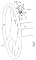
- FIG 3 depicts an embodiment of a combined gear and retarder control (6) according to the invention.
- the combined control (6) in this example is mounted in the steering column (7).
- This location at the steering wheel (8) has a number of advantages such as simplified operation, increased driving safety and better ergonomics. Other locations for the control are also conceivable, e.g. on the engine tunnel or the instrument panel.
- the control (6) in Figure 3 takes the form of a lever.
- the lever's stem (12) is mounted in the steering column (7) in a manner conventional for control levers.
- the retarder function is activated by moving the lever peripherally along the steering wheel rim.
- the braking effect increases gradually the further the lever is away from its initial position. If this movement for activating the retarder is executed clockwise (9) to increase the braking effect, the movement will resemble the well-established movement of previously known retarder levers, e.g. that depicted in Figure 1. This movement is therefore perceived as natural for the brake function. In this case the braking effect will be reduced by moving the lever back anticlockwise (11) along the steering wheel rim (10). The zero position for the retarder is maximum anticlockwise.
- the lever (6) has a rotatable portion (13) with which the driver can select the running position. This is done by turning the portion (13) step by step to the reverse, neutral or drive positions.
- the selectable running positions may be marked with letters on an unrotatable portion (33) of the lever. They may be marked, for example, R for reverse, N for neutral and D for drive in a manner known to most drivers.
- the rotatable portion (13) is advantageously provided with a mark (e.g. a dot) positioned centrally to the letter which denotes the running position selected.
- the letter which indicates the selected running position is preferably shown on a display on the instrument panel.
- the lever's end portion (14) serves as a push-button and by pressing it substantially horizontally towards (15) the steering wheel the driver can switch between the manual and automatic positions. He/she thus chooses between manual or automatic gearchanging.
- This push-button function only works when the rotary portion (13) is in its Drive position. Upward or downward gear changes are effected respectively by the driver moving the lever substantially vertically upwards towards (16) and downwards away from (17) the steering wheel.
- the upward and downward gearchange function is non-locking so that the lever always reverts to its original position, a certain distance away from the steering wheel, after the gear change. Gear changing can be effected irrespective of the running position selected.
- the lever (6) might also be equipped with a button or the like for activating the constant speed maintenance function.
- the embodiment according to Figure 3 results in a very compact and flexible lever.
- the rotary portion (13) is used for selecting any of the running programmes (Reverse, Neutral and Drive).
- the Drive programme When the Drive programme is selected, switching between manual and automatic is effected by pressing the end (14) of the lever.
- the rotary portion (13) will be used relatively infrequently.
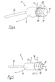
- FIGS. 4-9 depict further embodiments of the invention. These diagrams depict the levers (6) as free-standing, but their stem (12) is intended to be fastened to a steering column in a conventional manner.
- the retarder function is activated by moving the lever (6) peripherally along the steering wheel rim (10), preferably clockwise (9) (not shown in these drawings) in the same manner as in the embodiment depicted in Figure 3.
- the braking effect increases gradually the further clockwise (9) the lever is moved.
- To reduce the braking effect the lever is moved anticlockwise (11) along the undepicted steering wheel rim (10).
- the zero position for the retarder is maximum anticlockwise.
- the lever (6) depicted in Figure 4 incorporates two rotatable portions (18,19).
- the first (18) is for setting the selected running programme (Reverse, Neutral, Manual or Automatic) by turning the portion (18) step by step about the central axis of the lever.
- the second rotary portion (19) which is situated axially outside the first (18), effects upward and downward gearchanging.
- the rotary portion (19) may either be non-locking or have fixed positions. Changing up is effected by rotation in one direction, preferably towards the driver, and changing down by rotation in the opposite direction, preferably away from the driver.
- the retarder's constant speed maintenance function is activated by pressing the whole lever (6) axially inwards and preferably substantially horizontally (15) towards the steering column.
- the advantage of this embodiment is that the respective functions of the retarder and the gearchange mechanism are distinguished purely in terms of movement.
- the rotation (20) is associated with operating the opticruise (the gearbox) and the clockwise/anticlockwise movement (9,11) peripherally along the steering wheel is associated with operating the retarder. This reduces the risk of retarder control being confused with opticruise control.
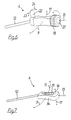
- the embodiment depicted in Figure 5 has great similarities with that in Figure 4.
- One difference is that the running programme is set by moving the lever (6) away from (17) and towards (16) the plane of the steering wheel in four positions (Reverse, Neutral, Manual and Automatic).
- the four running positions should be marked on the lever in some suitable manner, e.g. by letters situated logically on the lever.
- the running position selected is shown on a display on the instrument panel to make it easy for the driver to see which running position has been set at the time.
- the lever (6) incorporates a rotatable portion (19) for upward and downward gearchanging which functions in the same manner as depicted in Figure 4.
- the lever (6) depicted in Figure 6 likewise incorporates a rotary portion (18) for setting the running programme.
- the portion (18) can be turned step by step about the central axis of the lever to set any of the running programmes (Reverse, Neutral, Manual and Automatic).
- the end of the rotary portion (18), which here again is arranged in the outer end of the lever (6), has on it a non-locking push-button (21) with which the retarder's constant speed maintenance function can be activated in the same manner as described in Figure 5.
- Upward and downward gearchanging is effected with a non-locking toggle switch (22).
- Changing up is preferably by moving the toggle switch (22) towards (23) the driver and changing down by moving it away from (24) the driver, but the opposite is also conceivable.
- the fact that the toggle switch (22) is non-locking means that it can be operated with one or two fingers.
- the advantages of this embodiment are that all of the lever's functions are clearly distinguished in terms of movement and that the lever (6) is always the same distance away from the steering wheel.
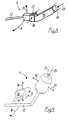
- Figure 7 depicts a lever (6) which incorporates a sliding knob (25) for setting the selected running programme.
- the sliding knob (25) is moved step by step between the running positions. These are preferably marked on the fixed portion (34) of the lever, along the path of movement of the sliding knob.
- the selected running programme is shown on a display on the instrument panel. Upward and downward gearchanging is effected in the same manner as in the embodiment according to Figure 3. This is a movement which is usual for gear changing in racing contexts.
- the retarder's constant speed maintenance function is activated by the whole lever being pushed in substantially horizontally towards (15) the steering wheel.
- the lever (6) depicted in Figure 8 incorporates a rotatable portion (18) for setting the running programme in the same manner as in the embodiment depicted in Figure 4.
- Upward and downward gearchanging is effected by two non-locking buttons (26,27), one for changing up and the other for changing down.
- the lever (6) is somewhat angled. This makes it easy for the driver to take hold of the lever in order to use the retarder, since the lever protrudes besides the steering wheel.
- the buttons are in a relatively protected location beneath the steering wheel, so that there is relatively little risk of the driver inadvertently touching them.
- the retarder's constant speed maintenance function is activated by pressing the outer end of the lever in line (29) with the central axis of the angled portion (28) of the lever (6).
- the lever (6) depicted in Figure 9 is also angled.
- the running programme (Reverse, Neutral, Manual or Automatic) is selected by sliding the lever (6) away from (31) and towards (30) the steering wheel in four positions. This resembles the movement of today's opticruise lever (depicted in Figure 1).
- the lever incorporates a permanently non-locking gearchange device (32) pivoting on the stem (12).
- upward gearchanging is effected by moving the device (32) substantially vertically upwards (16) the steering wheel. If downward gearchanging is desired, the device (32) is moved in the same manner downwards (17) away from the steering wheel. Changing up and down might also be effected by moving the device (32) substantially horizontally forward and rearwards respectively instead.
- the device (32) may either follow the lever's retarder movement (9,11) or be independent of that movement and always stay in the same position.
- the retarder's constant speed maintenance function is activated by the driver pressing a button (21) at the outer end of the lever in line (29) with the central axis of the angled portion of the lever (6).
- a multiplicity of further embodiments are possible by combining the patterns of movement described with the relevant functions (retarder braking, running programme selection, gear changing and constant speed maintenance).
- the lever may also be equipped with a so-called hill button and/or an automatic retarder activation button.
- the lever's retarder movement is alike in all the embodiments described, but other movements, e.g. rotation, movement towards/away from the steering wheel etc, are also conceivable.
- the lever and its movements may also be implemented with a satellite which protrudes from the vehicle's instrument panel and in which control devices corresponding to the lever can be incorporated. This solution also makes it easy for the driver to reach the control device for effecting gearchange and brake functions.
Landscapes
- Engineering & Computer Science (AREA)
- Mechanical Engineering (AREA)
- Transportation (AREA)
- Chemical & Material Sciences (AREA)
- Combustion & Propulsion (AREA)
- General Engineering & Computer Science (AREA)
- Physics & Mathematics (AREA)
- General Physics & Mathematics (AREA)
- Automation & Control Theory (AREA)
- Arrangement Or Mounting Of Control Devices For Change-Speed Gearing (AREA)
- Control Of Transmission Device (AREA)
- Mechanical Control Devices (AREA)
Claims (13)
- Steuereinrichtung (6) in einem Fahrzeug, die mit einem halbautomatischen Getriebe verbunden und für dessen Betätigung vorgesehen ist, in mehrere Gangwechsel-Funktionsstellungen einstellbar ist und in mindestens einer Gangwechsel-Funktionsstellung für Vorwärtsfahrt betätigbar ist, damit ein Gangwechsel stattfindet, dadurch gekennzeichnet, dass die Steuereinrichtung (6) auch mit einer zusätzlichen Retarderbremse verbunden und zu deren Betätigung vorgesehen ist.
- Steuereinrichtung (6) nach Patentanspruch 1, dadurch gekennzeichnet, dass die Steuereinrichtung (6) aus einem Hebel (6) besteht, der im Bereich nahe dem Lenkrad (8) des Fahrzeugs angeordnet ist, so dass der Hebel (6) vom Fahrer betätigt werden kann, ohne dass dieser seine ursprüngliche Fahrhaltung zu ändern braucht, und vorzugsweise ohne eine Hand vom Lenkrad (8) zu entfernen.
- Steuereinrichtung nach Anspruch 1 oder 2, dadurch gekennzeichnet, dass der Hebel (6) verschiedene Bewegungsmuster zum Ausführen von Funktionen hat, die mit dem Getriebe bzw. der zusätzlichen Bremse verbunden sind.
- Steuereinrichtung nach Patentanspruch 3, dadurch gekennzeichnet, dass die zusätzliche Bremse eine in unterschiedlichem Ausmaß betätigbare Bremse, ein sogenannter Retarder ist und dass der Hebel (6) in einer zum Lenkrad (8) parallelen Ebene und entlang des Kranzes (10) des Lenkrades aus einer Stellung heraus beweglich ist, in welcher der Retarder inaktiv ist, und dass die Wirkung des Retarders aktiviert wird und die Bremswirkung zunimmt, je weiter der Hebel bewegt wird.
- Steuereinrichtung nach Patentanspruch 4, dadurch gekennzeichnet, dass der Hebel (6) einen Abschnitt (13, 18) umfasst, der um die Längsachse des Hebels drehbar ist, um gewünschte Gangwechsel-Funktionsstellungen einzustellen, und dass dieser Abschnitt (13, 18) schrittweise in mindestens eine Rückwärtsstellung, eine neutrale Stellung und eine Fahrstellung gedreht werden kann.
- Steuereinrichtung nach Patentanspruch 4, dadurch gekennzeichnet, dass der Hebel (6) schrittweise zu der in bezug auf den äußeren Abschnitt des Zentrums des Lenkrades längsgerichteten Mittellinie des Hebels hin und von ihr weg in eine Richtung radial und normal (16, 17, 30, 31) zu dieser Mittellinie bewegbar ist, und dass jeder Schritt einer Gangwechsel-Funktionsstellung entspricht.
- Steuereinrichtung nach Patentanspruch 4, dadurch gekennzeichnet, dass der Hebel (6) einen Schiebeknopf (25) aufweist, der schrittweise in der Längsrichtung des Hebels bewegbar ist, und dass jeder Schritt einer Gangwechsel-Funktionsstellung entspricht.
- Steuereinrichtung nach einem der Patentansprüche 5-7, dadurch gekennzeichnet, dass der Hebel (6) oder ein Abschnitt (32) des Hebels aus einer mit der längsgerichteten Mittellinie des Stiels (12) des Hebels im Wesentlichen parallelen Ebene in nicht verriegelnder Weise nach oben (16) und nach unten (17) bewegbar ist und dadurch einen Gangwechsel nach oben bzw. nach unten bewirkt.
- Steuereinrichtung nach einem der Patentansprüche 5-6, dadurch gekennzeichnet, dass der Hebel (6) einen drehbaren Abschnitt (17) aufweist, der schrittweise um die Mittelachse des Hebels drehbar ist, um Gänge nach Wunsch einzustellen.
- Steuereinrichtung nach einem der Patentansprüche 5-6, dadurch gekennzeichnet, dass der Hebel (6) einen nicht-verriegelnd drehbaren Abschnitt (19, 22) aufweist, der nicht-verriegelnd um die Mittellinie des Hebels aus einer neutralen Stellung in Richtung zu (23) und weg von (24) dem Fahrer drehbar ist für ein Herauf- bzw. Herunterschalten.
- Steuereinrichtung nach einem der Patentansprüche 5-7, dadurch gekennzeichnet, dass der Hebel (6) zwei nicht verriegelnde Knöpfe (26, 27) aufweist, und dass ein Heraufschalten durch Drücken eines von ihnen (26, 27), und ein Herunterschalten durch Drücken des anderen (27, 26) bewirkt wird.
- Steuereinrichtung nach Patentanspruch 5, dadurch gekennzeichnet, dass der Hebel (6) einen Endabschnitt (14) aufweist, der in Fahrstellung des Hebels nicht-verriegelnd in der Längsrichtung des Hebels einwärts in Richtung (15) zum Lenkrad bewegbar ist, um ein Umschalten zwischen den Funktionsstellungen für manuellen und automatischen Gangwechsel zu bewirken.
- Steuereinrichtung nach irgendeinem der Patentansprüche, dadurch gekennzeichnet, dass die Einrichtung (6) ein Bauteil (21) zum Aktivieren einer Geschwindigkeits-Konstanthaltungsfunktion aufweist. 5641
Applications Claiming Priority (3)
| Application Number | Priority Date | Filing Date | Title |
|---|---|---|---|
| SE9904751A SE9904751L (sv) | 1999-12-23 | 1999-12-23 | Manöverdon i ett fordon |
| SE9904751 | 1999-12-23 | ||
| PCT/SE2000/002623 WO2001047738A1 (en) | 1999-12-23 | 2000-12-21 | Control arrangement for a vehicle |
Publications (2)
| Publication Number | Publication Date |
|---|---|
| EP1246732A1 EP1246732A1 (de) | 2002-10-09 |
| EP1246732B1 true EP1246732B1 (de) | 2004-04-07 |
Family
ID=20418277
Family Applications (1)
| Application Number | Title | Priority Date | Filing Date |
|---|---|---|---|
| EP00989125A Expired - Lifetime EP1246732B1 (de) | 1999-12-23 | 2000-12-21 | Steuereinheit für fahrzeug |
Country Status (8)
| Country | Link |
|---|---|
| US (1) | US6945349B2 (de) |
| EP (1) | EP1246732B1 (de) |
| JP (1) | JP4792188B2 (de) |
| AT (1) | ATE263689T1 (de) |
| BR (2) | BRPI0016512B1 (de) |
| DE (1) | DE60009749T2 (de) |
| SE (1) | SE9904751L (de) |
| WO (1) | WO2001047738A1 (de) |
Families Citing this family (27)
| Publication number | Priority date | Publication date | Assignee | Title |
|---|---|---|---|---|
| FR2848506B1 (fr) | 2002-12-11 | 2005-12-16 | Peugeot Citroen Automobiles Sa | Module integral de controle de marche d'un vehicule automobile |
| KR100488740B1 (ko) * | 2003-08-27 | 2005-05-11 | 현대자동차주식회사 | 차량용 시프트 바이 와이어 시스템의 시프팅 장치 |
| US20050274563A1 (en) * | 2004-05-28 | 2005-12-15 | Bruce Ahnafield | Joystick-operated driving system |
| FR2879973B1 (fr) * | 2004-12-23 | 2008-06-13 | Renault Sas | Agencement de commandes sous volant |
| SE529592C2 (sv) * | 2005-02-03 | 2007-09-25 | Scania Cv Abp | Manöverdon för manövrering av en halvautomatisk växellåda hos ett fordon samt inrättning hos ett fordon innefattande ett sådant manöverdon |
| FR2887187B1 (fr) * | 2005-06-15 | 2008-10-10 | Peugeot Citroen Automobiles Sa | Support pour organe de commande de vehicule automobile |
| DE102005036923A1 (de) * | 2005-08-05 | 2007-02-08 | Bayerische Motoren Werke Ag | Bedieneinrichtung für ein Fahrerassistenzsystem für ein Kraftfahrzeug |
| DE102006004080A1 (de) | 2006-01-28 | 2007-08-02 | Zf Friedrichshafen Ag | Antriebsstrang eines Kraftfahrzeuges |
| JP4705529B2 (ja) * | 2006-07-21 | 2011-06-22 | 株式会社東海理化電機製作所 | レンジ切替操作装置 |
| JP4629627B2 (ja) * | 2006-07-21 | 2011-02-09 | 株式会社東海理化電機製作所 | レンジ切替操作装置 |
| SE530989C2 (sv) * | 2007-03-26 | 2008-11-11 | Volvo Lastvagnar Ab | Manöveranordning för ett fordon |
| DE102007022527A1 (de) * | 2007-05-14 | 2008-11-20 | Bayerische Motoren Werke Aktiengesellschaft | Bedieneinrichtung |
| US7775136B2 (en) * | 2007-08-13 | 2010-08-17 | Schwulst Kyle E E | Twist-grip handlebar controller |
| JP5662135B2 (ja) * | 2010-12-22 | 2015-01-28 | 富士重工業株式会社 | 運転操作装置 |
| KR101693890B1 (ko) * | 2011-11-14 | 2017-01-06 | 현대자동차주식회사 | 차량의 amt 셀렉터 레버 작동구조 |
| JP5882066B2 (ja) * | 2012-01-19 | 2016-03-09 | 日立建機株式会社 | 作業車両の制御装置 |
| JP5896301B2 (ja) * | 2012-12-25 | 2016-03-30 | 三菱自動車工業株式会社 | 回生ブレーキ制御装置 |
| US10384546B2 (en) * | 2014-01-13 | 2019-08-20 | Ge Global Sourcing Llc | System and method for controlling a vehicle |
| KR101655624B1 (ko) * | 2014-12-23 | 2016-09-07 | 현대자동차주식회사 | 차량의 통합형 전자식 변속레버 어셈블리 |
| DE102015000720B4 (de) | 2015-01-21 | 2023-06-01 | Man Truck & Bus Se | Auswahlvorrichtung zur Auswahl von Fahrstufen und Fahrprogrammen für ein automatisiertes oder automatisches Getriebe |
| US10100919B1 (en) | 2016-06-10 | 2018-10-16 | Kongsberg Power Products Systems I, Inc. | Shifter assembly |
| US11014450B2 (en) | 2017-02-24 | 2021-05-25 | Ford Global Technologies, Llc | Stalk mounted telescoping rotary shift knob |
| DE102017210254A1 (de) | 2017-06-20 | 2018-12-20 | Zf Friedrichshafen Ag | Bedieneinrichtung für ein Lenkrad eines Fahrzeugs |
| KR102381747B1 (ko) * | 2017-07-24 | 2022-04-04 | 현대자동차주식회사 | 변속 장치를 포함하는 차량 |
| USD875003S1 (en) | 2018-04-13 | 2020-02-11 | Paccar Inc | Stalk mounted automated manual shifter |
| KR20210020069A (ko) * | 2018-06-15 | 2021-02-23 | 지에이치에스피, 아이엔씨. | 2차 회전식 손잡이를 갖는 회전식 시프터 |
| WO2022208228A1 (en) * | 2021-03-30 | 2022-10-06 | Ghsp, Inc. | Vehicle drive train control interface |
Citations (2)
| Publication number | Priority date | Publication date | Assignee | Title |
|---|---|---|---|---|
| EP0209431A1 (de) * | 1985-06-28 | 1987-01-21 | Regie Nationale Des Usines Renault | Kombinierte Schaltgetriebe- und Handbremssteuervorrichtung |
| DE19632254C1 (de) * | 1996-08-09 | 1997-10-23 | Volkswagen Ag | Handbremshebel mit integrierter Getriebeschaltung |
Family Cites Families (32)
| Publication number | Priority date | Publication date | Assignee | Title |
|---|---|---|---|---|
| US3727730A (en) * | 1972-01-31 | 1973-04-17 | Caterpillar Tractor Co | Vehicle power and brake cooling control |
| JPS6022525Y2 (ja) * | 1978-10-06 | 1985-07-04 | 株式会社東海理化電機製作所 | 自動車用レバ−コンビネ−シヨンスイツチ |
| JPS5565752A (en) * | 1978-10-30 | 1980-05-17 | Volvo Ab | Speed changer for vehicle |
| US4503300A (en) * | 1983-08-03 | 1985-03-05 | Dana Corporation | Control assembly with multi-axis mounting connection |
| FR2600285B1 (fr) * | 1986-06-20 | 1988-10-07 | Renault | Dispositif de commande electromecanique de boite de vitesses automatique |
| US4742806A (en) * | 1986-09-10 | 1988-05-10 | Tart Jr Earl D | Auxiliary engine braking system |
| US5099720A (en) * | 1987-02-26 | 1992-03-31 | Zahnradfabrik Friedrichshafen Ag | Control mechanism for an automatic gear-shifting transmission using turn signal control unit |
| US4924960A (en) | 1988-10-12 | 1990-05-15 | Robal, Inc. | Highly reliable remote control system |
| US4966044A (en) * | 1989-05-30 | 1990-10-30 | J. I. Case Company | Directional control system for a tractor transmission |
| SE9003318L (sv) * | 1990-10-19 | 1991-11-11 | Saab Automobile | Reglage, arrangemang och foerfarande foer reglering av servoorgan foer motorfordons framfoerande |
| IT1245452B (it) * | 1991-03-13 | 1994-09-20 | Iveco Fiat | Sistema di comando di un rallentatore idraulico per veicoli industriali e veicolo provvisto di tale sistema |
| GB9206344D0 (en) * | 1992-03-24 | 1992-05-06 | Lucas Ind Plc | Improved braking in electronic braking systems |
| JPH05301533A (ja) * | 1992-04-27 | 1993-11-16 | Isuzu Motors Ltd | 車両用シフトレバー |
| JPH0648216A (ja) * | 1992-07-29 | 1994-02-22 | Toyota Motor Corp | 定速走行装置付車両の自動変速機の制御装置 |
| DE19537273A1 (de) * | 1995-10-06 | 1997-04-10 | Zahnradfabrik Friedrichshafen | Einrichtung zur Geschwindigkeitsregelung von Fahrzeugen |
| JP3471149B2 (ja) * | 1995-10-11 | 2003-11-25 | ジヤトコ株式会社 | 補助ブレーキ装置 |
| JPH09254676A (ja) * | 1996-03-19 | 1997-09-30 | Tokai Rika Co Ltd | 自動変速機の操作装置 |
| JP3743692B2 (ja) * | 1997-03-26 | 2006-02-08 | 株式会社小松製作所 | リターダ自動制御装置 |
| US5957001A (en) * | 1997-05-01 | 1999-09-28 | Eaton Corporation | Transmission control lever with user interface |
| DE19721166C2 (de) * | 1997-05-21 | 1998-11-26 | Voith Turbo Kg | Einrichtung und Verfahren zur Einstellung von Retarderbremsprogrammen und/oder Retarderbremsfunktionen |
| SE517480C2 (sv) * | 1997-08-11 | 2002-06-11 | Volvo Car Corp | Sätt och system för reglering av ett fordons hastighet |
| DE19915892B4 (de) * | 1998-04-09 | 2008-11-06 | Nissan Motor Co., Ltd., Yokohama | Schaltvorrichtung für ein Automatikgetriebe |
| DE19822860C2 (de) * | 1998-05-22 | 2002-08-08 | Daimler Chrysler Ag | Verfahren und Vorrichtung zum Abbremsen eines Fahrzeugs |
| DE19832870C1 (de) * | 1998-07-22 | 1999-04-08 | Porsche Ag | Bedienelement für eine Abstandsregeleinrichtung für Fahrzeuge |
| JP3495259B2 (ja) * | 1998-07-31 | 2004-02-09 | ナイルス株式会社 | 車両用レバースイッチの構造 |
| US6151977A (en) * | 1999-02-26 | 2000-11-28 | Freightliner Corporation | Lever assembly for an electronically controllable vehicle transmission |
| DE19916924A1 (de) * | 1999-04-14 | 2000-10-19 | Bayerische Motoren Werke Ag | Kraftfahrzeug mit einer Wähleinrichtung |
| GB2353832A (en) * | 1999-09-04 | 2001-03-07 | New Holland Uk Ltd | Gear change command mechanism for a vehicle |
| US6172312B1 (en) * | 1999-10-20 | 2001-01-09 | Valeo Electrical Systems, Inc. | Combination transmission gear select and auxiliary switch lever |
| JP2001185006A (ja) * | 1999-12-27 | 2001-07-06 | Isuzu Motors Ltd | 車両における電装品操作スイッチの自動復帰制御方法 |
| JP2001248716A (ja) * | 2000-03-07 | 2001-09-14 | Honda Motor Co Ltd | 車両用自動変速機のシフト制御装置 |
| IT1320577B1 (it) * | 2000-08-01 | 2003-12-10 | Magneti Marelli Spa | Dispositivo selettore di marce per cambio automatizzato. |
-
1999
- 1999-12-23 SE SE9904751A patent/SE9904751L/ not_active IP Right Cessation
-
2000
- 2000-12-21 US US10/169,049 patent/US6945349B2/en not_active Expired - Lifetime
- 2000-12-21 EP EP00989125A patent/EP1246732B1/de not_active Expired - Lifetime
- 2000-12-21 AT AT00989125T patent/ATE263689T1/de not_active IP Right Cessation
- 2000-12-21 JP JP2001548304A patent/JP4792188B2/ja not_active Expired - Lifetime
- 2000-12-21 BR BRPI0016512-3A patent/BRPI0016512B1/pt unknown
- 2000-12-21 DE DE60009749T patent/DE60009749T2/de not_active Expired - Lifetime
- 2000-12-21 WO PCT/SE2000/002623 patent/WO2001047738A1/en active IP Right Grant
- 2000-12-21 BR BR0016512-3A patent/BR0016512A/pt active IP Right Grant
Patent Citations (2)
| Publication number | Priority date | Publication date | Assignee | Title |
|---|---|---|---|---|
| EP0209431A1 (de) * | 1985-06-28 | 1987-01-21 | Regie Nationale Des Usines Renault | Kombinierte Schaltgetriebe- und Handbremssteuervorrichtung |
| DE19632254C1 (de) * | 1996-08-09 | 1997-10-23 | Volkswagen Ag | Handbremshebel mit integrierter Getriebeschaltung |
Also Published As
| Publication number | Publication date |
|---|---|
| SE514131C2 (sv) | 2001-01-08 |
| US20030000763A1 (en) | 2003-01-02 |
| DE60009749D1 (de) | 2004-05-13 |
| US6945349B2 (en) | 2005-09-20 |
| BRPI0016512B1 (pt) | 2017-07-04 |
| JP4792188B2 (ja) | 2011-10-12 |
| WO2001047738A1 (en) | 2001-07-05 |
| ATE263689T1 (de) | 2004-04-15 |
| DE60009749T2 (de) | 2005-04-28 |
| SE9904751L (sv) | 2001-01-08 |
| EP1246732A1 (de) | 2002-10-09 |
| SE9904751D0 (sv) | 1999-12-23 |
| BR0016512A (pt) | 2002-09-17 |
| JP2003518464A (ja) | 2003-06-10 |
Similar Documents
| Publication | Publication Date | Title |
|---|---|---|
| EP1246732B1 (de) | Steuereinheit für fahrzeug | |
| JP2003518464A5 (de) | ||
| JP4452349B2 (ja) | 車両用の加速・減速意思入力装置 | |
| SE506002C2 (sv) | Regleranordning för styrning och transmissionsväxling | |
| RU2515005C2 (ru) | Устройство и способ управления автоматической коробкой передач автомобиля | |
| JP2001039176A (ja) | オートマチック式伝動装置用の切換装置 | |
| US20190375392A1 (en) | Device and method for controlling a vehicle and vehicle | |
| US4850238A (en) | Shiftlever mechanism for an automatic transmission | |
| JPH09254676A (ja) | 自動変速機の操作装置 | |
| JP2003312301A (ja) | 手動変速モードを具備した自動変速機用コラムタイプシフトレバーの構造 | |
| US6474187B1 (en) | Device for changing the gears of an automatic transmission | |
| JP3718646B2 (ja) | スイッチ装置 | |
| JPH05118414A (ja) | 自動変速機の操作装置 | |
| EP4073401A1 (de) | Steuerschnittstellensystem zum steuern eines fahrzeugs über eine elektronische steuereinheit, wobei das fahrzeug dieses system umfasst | |
| JPH05203020A (ja) | 自動変速機のシフトパターン切換装置 | |
| JPH10329567A (ja) | 自動車のステアリングスイッチ | |
| EP1363048B1 (de) | Steuerungsvorrichtung für ein Kraftfahrzeug | |
| JP2000027982A (ja) | 自動変速機の制御装置 | |
| JPH066057U (ja) | 自動車用変速装置の変速操作装置 | |
| CN117098683A (zh) | 车辆传动系控制界面 | |
| JP2966022B2 (ja) | 車両用自動変速機の操作装置 | |
| KR100461832B1 (ko) | 수동 변속 모드가 구비된 자동 변속기용 컬럼 타입 시프트 레버 | |
| JPH03253426A (ja) | 車両用自動変速機のシフトレバー | |
| JP3017500B2 (ja) | 自動変速機の制御装置 | |
| JP2918963B2 (ja) | 操作レバー装置 |
Legal Events
| Date | Code | Title | Description |
|---|---|---|---|
| PUAI | Public reference made under article 153(3) epc to a published international application that has entered the european phase |
Free format text: ORIGINAL CODE: 0009012 |
|
| 17P | Request for examination filed |
Effective date: 20020723 |
|
| AK | Designated contracting states |
Kind code of ref document: A1 Designated state(s): AT BE CH CY DE DK ES FI FR GB GR IE IT LI LU MC NL PT SE TR |
|
| GRAP | Despatch of communication of intention to grant a patent |
Free format text: ORIGINAL CODE: EPIDOSNIGR1 |
|
| GRAS | Grant fee paid |
Free format text: ORIGINAL CODE: EPIDOSNIGR3 |
|
| GRAA | (expected) grant |
Free format text: ORIGINAL CODE: 0009210 |
|
| AK | Designated contracting states |
Kind code of ref document: B1 Designated state(s): AT BE CH CY DE DK ES FI FR GB GR IE IT LI LU MC NL PT SE TR |
|
| PG25 | Lapsed in a contracting state [announced via postgrant information from national office to epo] |
Ref country code: CY Free format text: LAPSE BECAUSE OF FAILURE TO SUBMIT A TRANSLATION OF THE DESCRIPTION OR TO PAY THE FEE WITHIN THE PRESCRIBED TIME-LIMIT Effective date: 20040407 Ref country code: CH Free format text: LAPSE BECAUSE OF FAILURE TO SUBMIT A TRANSLATION OF THE DESCRIPTION OR TO PAY THE FEE WITHIN THE PRESCRIBED TIME-LIMIT Effective date: 20040407 Ref country code: BE Free format text: LAPSE BECAUSE OF FAILURE TO SUBMIT A TRANSLATION OF THE DESCRIPTION OR TO PAY THE FEE WITHIN THE PRESCRIBED TIME-LIMIT Effective date: 20040407 Ref country code: AT Free format text: LAPSE BECAUSE OF FAILURE TO SUBMIT A TRANSLATION OF THE DESCRIPTION OR TO PAY THE FEE WITHIN THE PRESCRIBED TIME-LIMIT Effective date: 20040407 Ref country code: FI Free format text: LAPSE BECAUSE OF FAILURE TO SUBMIT A TRANSLATION OF THE DESCRIPTION OR TO PAY THE FEE WITHIN THE PRESCRIBED TIME-LIMIT Effective date: 20040407 Ref country code: NL Free format text: LAPSE BECAUSE OF FAILURE TO SUBMIT A TRANSLATION OF THE DESCRIPTION OR TO PAY THE FEE WITHIN THE PRESCRIBED TIME-LIMIT Effective date: 20040407 Ref country code: TR Free format text: LAPSE BECAUSE OF FAILURE TO SUBMIT A TRANSLATION OF THE DESCRIPTION OR TO PAY THE FEE WITHIN THE PRESCRIBED TIME-LIMIT Effective date: 20040407 Ref country code: LI Free format text: LAPSE BECAUSE OF FAILURE TO SUBMIT A TRANSLATION OF THE DESCRIPTION OR TO PAY THE FEE WITHIN THE PRESCRIBED TIME-LIMIT Effective date: 20040407 |
|
| REG | Reference to a national code |
Ref country code: GB Ref legal event code: FG4D |
|
| REG | Reference to a national code |
Ref country code: CH Ref legal event code: EP |
|
| REF | Corresponds to: |
Ref document number: 60009749 Country of ref document: DE Date of ref document: 20040513 Kind code of ref document: P |
|
| REG | Reference to a national code |
Ref country code: IE Ref legal event code: FG4D |
|
| PG25 | Lapsed in a contracting state [announced via postgrant information from national office to epo] |
Ref country code: DK Free format text: LAPSE BECAUSE OF FAILURE TO SUBMIT A TRANSLATION OF THE DESCRIPTION OR TO PAY THE FEE WITHIN THE PRESCRIBED TIME-LIMIT Effective date: 20040707 Ref country code: GR Free format text: LAPSE BECAUSE OF FAILURE TO SUBMIT A TRANSLATION OF THE DESCRIPTION OR TO PAY THE FEE WITHIN THE PRESCRIBED TIME-LIMIT Effective date: 20040707 Ref country code: SE Free format text: LAPSE BECAUSE OF FAILURE TO SUBMIT A TRANSLATION OF THE DESCRIPTION OR TO PAY THE FEE WITHIN THE PRESCRIBED TIME-LIMIT Effective date: 20040707 |
|
| PG25 | Lapsed in a contracting state [announced via postgrant information from national office to epo] |
Ref country code: ES Free format text: LAPSE BECAUSE OF FAILURE TO SUBMIT A TRANSLATION OF THE DESCRIPTION OR TO PAY THE FEE WITHIN THE PRESCRIBED TIME-LIMIT Effective date: 20040718 |
|
| NLV1 | Nl: lapsed or annulled due to failure to fulfill the requirements of art. 29p and 29m of the patents act | ||
| REG | Reference to a national code |
Ref country code: CH Ref legal event code: PL |
|
| PG25 | Lapsed in a contracting state [announced via postgrant information from national office to epo] |
Ref country code: IE Free format text: LAPSE BECAUSE OF NON-PAYMENT OF DUE FEES Effective date: 20041221 Ref country code: LU Free format text: LAPSE BECAUSE OF NON-PAYMENT OF DUE FEES Effective date: 20041221 |
|
| ET | Fr: translation filed | ||
| PG25 | Lapsed in a contracting state [announced via postgrant information from national office to epo] |
Ref country code: MC Free format text: LAPSE BECAUSE OF NON-PAYMENT OF DUE FEES Effective date: 20041231 |
|
| PLBE | No opposition filed within time limit |
Free format text: ORIGINAL CODE: 0009261 |
|
| STAA | Information on the status of an ep patent application or granted ep patent |
Free format text: STATUS: NO OPPOSITION FILED WITHIN TIME LIMIT |
|
| 26N | No opposition filed |
Effective date: 20050110 |
|
| REG | Reference to a national code |
Ref country code: IE Ref legal event code: MM4A |
|
| PG25 | Lapsed in a contracting state [announced via postgrant information from national office to epo] |
Ref country code: PT Free format text: LAPSE BECAUSE OF NON-PAYMENT OF DUE FEES Effective date: 20040907 |
|
| REG | Reference to a national code |
Ref country code: DE Ref legal event code: R008 Ref document number: 60009749 Country of ref document: DE Ref country code: DE Ref legal event code: R039 Ref document number: 60009749 Country of ref document: DE |
|
| REG | Reference to a national code |
Ref country code: DE Ref legal event code: R039 Ref document number: 60009749 Country of ref document: DE Effective date: 20150130 |
|
| REG | Reference to a national code |
Ref country code: FR Ref legal event code: PLFP Year of fee payment: 16 |
|
| REG | Reference to a national code |
Ref country code: FR Ref legal event code: PLFP Year of fee payment: 17 |
|
| REG | Reference to a national code |
Ref country code: DE Ref legal event code: R040 Ref document number: 60009749 Country of ref document: DE Ref country code: DE Ref legal event code: R097 Ref document number: 60009749 Country of ref document: DE |
|
| REG | Reference to a national code |
Ref country code: FR Ref legal event code: PLFP Year of fee payment: 18 |
|
| PGFP | Annual fee paid to national office [announced via postgrant information from national office to epo] |
Ref country code: DE Payment date: 20191210 Year of fee payment: 20 |
|
| PGFP | Annual fee paid to national office [announced via postgrant information from national office to epo] |
Ref country code: FR Payment date: 20191115 Year of fee payment: 20 Ref country code: IT Payment date: 20191209 Year of fee payment: 20 |
|
| PGFP | Annual fee paid to national office [announced via postgrant information from national office to epo] |
Ref country code: GB Payment date: 20191219 Year of fee payment: 20 |
|
| REG | Reference to a national code |
Ref country code: DE Ref legal event code: R071 Ref document number: 60009749 Country of ref document: DE |
|
| REG | Reference to a national code |
Ref country code: GB Ref legal event code: PE20 Expiry date: 20201220 |
|
| PG25 | Lapsed in a contracting state [announced via postgrant information from national office to epo] |
Ref country code: GB Free format text: LAPSE BECAUSE OF EXPIRATION OF PROTECTION Effective date: 20201220 |
|
| P01 | Opt-out of the competence of the unified patent court (upc) registered |
Effective date: 20230518 |