EP1170655A2 - Schaltungseinrichtung für ein Übertragungssystem - Google Patents
Schaltungseinrichtung für ein Übertragungssystem Download PDFInfo
- Publication number
- EP1170655A2 EP1170655A2 EP01305438A EP01305438A EP1170655A2 EP 1170655 A2 EP1170655 A2 EP 1170655A2 EP 01305438 A EP01305438 A EP 01305438A EP 01305438 A EP01305438 A EP 01305438A EP 1170655 A2 EP1170655 A2 EP 1170655A2
- Authority
- EP
- European Patent Office
- Prior art keywords
- grip
- connecting member
- opening
- mounting
- shift
- Prior art date
- Legal status (The legal status is an assumption and is not a legal conclusion. Google has not performed a legal analysis and makes no representation as to the accuracy of the status listed.)
- Withdrawn
Links
Images

Classifications
-
- G—PHYSICS
- G05—CONTROLLING; REGULATING
- G05G—CONTROL DEVICES OR SYSTEMS INSOFAR AS CHARACTERISED BY MECHANICAL FEATURES ONLY
- G05G1/00—Controlling members, e.g. knobs or handles; Assemblies or arrangements thereof; Indicating position of controlling members
- G05G1/04—Controlling members for hand actuation by pivoting movement, e.g. levers
- G05G1/06—Details of their grip parts
-
- F—MECHANICAL ENGINEERING; LIGHTING; HEATING; WEAPONS; BLASTING
- F16—ENGINEERING ELEMENTS AND UNITS; GENERAL MEASURES FOR PRODUCING AND MAINTAINING EFFECTIVE FUNCTIONING OF MACHINES OR INSTALLATIONS; THERMAL INSULATION IN GENERAL
- F16H—GEARING
- F16H59/00—Control inputs to control units of change-speed- or reversing-gearings for conveying rotary motion
- F16H59/02—Selector apparatus
- F16H59/0278—Constructional features of the selector lever, e.g. grip parts, mounting or manufacturing
- F16H2059/0282—Lever handles with lock mechanisms, e.g. for allowing selection of reverse gear or releasing lever from park position
-
- Y—GENERAL TAGGING OF NEW TECHNOLOGICAL DEVELOPMENTS; GENERAL TAGGING OF CROSS-SECTIONAL TECHNOLOGIES SPANNING OVER SEVERAL SECTIONS OF THE IPC; TECHNICAL SUBJECTS COVERED BY FORMER USPC CROSS-REFERENCE ART COLLECTIONS [XRACs] AND DIGESTS
- Y10—TECHNICAL SUBJECTS COVERED BY FORMER USPC
- Y10T—TECHNICAL SUBJECTS COVERED BY FORMER US CLASSIFICATION
- Y10T74/00—Machine element or mechanism
- Y10T74/20—Control lever and linkage systems
- Y10T74/20012—Multiple controlled elements
- Y10T74/20018—Transmission control
- Y10T74/2014—Manually operated selector [e.g., remotely controlled device, lever, push button, rotary dial, etc.]
-
- Y—GENERAL TAGGING OF NEW TECHNOLOGICAL DEVELOPMENTS; GENERAL TAGGING OF CROSS-SECTIONAL TECHNOLOGIES SPANNING OVER SEVERAL SECTIONS OF THE IPC; TECHNICAL SUBJECTS COVERED BY FORMER USPC CROSS-REFERENCE ART COLLECTIONS [XRACs] AND DIGESTS
- Y10—TECHNICAL SUBJECTS COVERED BY FORMER USPC
- Y10T—TECHNICAL SUBJECTS COVERED BY FORMER US CLASSIFICATION
- Y10T74/00—Machine element or mechanism
- Y10T74/20—Control lever and linkage systems
- Y10T74/20576—Elements
- Y10T74/20582—Levers
- Y10T74/20612—Hand
-
- Y—GENERAL TAGGING OF NEW TECHNOLOGICAL DEVELOPMENTS; GENERAL TAGGING OF CROSS-SECTIONAL TECHNOLOGIES SPANNING OVER SEVERAL SECTIONS OF THE IPC; TECHNICAL SUBJECTS COVERED BY FORMER USPC CROSS-REFERENCE ART COLLECTIONS [XRACs] AND DIGESTS
- Y10—TECHNICAL SUBJECTS COVERED BY FORMER USPC
- Y10T—TECHNICAL SUBJECTS COVERED BY FORMER US CLASSIFICATION
- Y10T74/00—Machine element or mechanism
- Y10T74/20—Control lever and linkage systems
- Y10T74/20576—Elements
- Y10T74/20636—Detents
- Y10T74/20648—Interrelated lever release
-
- Y—GENERAL TAGGING OF NEW TECHNOLOGICAL DEVELOPMENTS; GENERAL TAGGING OF CROSS-SECTIONAL TECHNOLOGIES SPANNING OVER SEVERAL SECTIONS OF THE IPC; TECHNICAL SUBJECTS COVERED BY FORMER USPC CROSS-REFERENCE ART COLLECTIONS [XRACs] AND DIGESTS
- Y10—TECHNICAL SUBJECTS COVERED BY FORMER USPC
- Y10T—TECHNICAL SUBJECTS COVERED BY FORMER US CLASSIFICATION
- Y10T74/00—Machine element or mechanism
- Y10T74/20—Control lever and linkage systems
- Y10T74/20576—Elements
- Y10T74/20636—Detents
- Y10T74/20672—Lever engaging rack
- Y10T74/20696—Finger lever release
Definitions
- the invention relates to a shift knob and a shift lever, which are adapted to a vehicle.
- a shift lever as a component of a transmission system for operation of transmission function of a vehicle, has at its upper end a shift knob for the driver to grip when driving.
- the shift knob is provided with a knob button for push-in operation in a shift operation.
- the grip of shift knob is made of a resin, a leather, aluminum or a wood, which improves its appearance and touch quality.
- response to client needs causes the production of a plurality of kinds of vehicles, which are assembled with shift knobs whose grips are made of different kinds of materials respectively.
- An object of the present invention is to provide a shift lever which facilitates the exchange of a grip as a constituent component of a shift knob and a shift lever.
- a first aspect of the invention provides the following shift knob.
- the knob includes a grip.
- a mechanism is for transmission operation via the grip.
- a connecting member is assembled with the mechanism.
- the connecting member is mounted to the grip.
- a second aspect of the invention provides the following shift lever.
- the shift lever includes a grip.
- a lever is for operation with the grip.
- the lever has a transmission member incorporated therein.
- a mechanism is for operating the transmission member via the grip.
- a connecting member is assembled with the mechanism.
- the connecting member is fixed to the lever.
- the connecting member has the transmission member incorporated therein.
- the connecting member is mounted to the grip.
- the grip defines a first opening on a side thereof, and the connecting member is inserted in the first opening.
- the grip has a mounting means for mounting the connecting member within the first opening.
- the grip includes a second opening in communication with the first opening through the grip.
- the mechanism includes a button pivotable on the connecting member.
- the button projects from the first opening.
- the button and the first opening define a space therebetween.
- the shift lever further includes a cover for covering the space between the button and the first opening.
- the mechanism includes a first rotation member for pivotal motion on the connecting member; a second rotation member to be pushed by the first rotation member for pivotal motion on the connecting member and to be brought into contact with the transmission member; and a biasing member for biasing against the first rotation member.
- the connecting member supports the first rotation and the second rotation members.
- the biasing member is located between the connecting member and the first rotation member.
- the connecting member is fixed in the first opening, using the space.
- a third aspect of the invention provides the following assembly method of a shift lever.
- a mechanism is assembled to a connecting member.
- the connecting member is inserted in a second opening of a grip via a first opening of the grip.
- the connecting member is mounted to the grip.
- the assembly method further includes fixing a lever to the connecting member.
- the mechanism is assembled to the connecting member first, the connecting member is then mounted to the grip, thus facilitating the exchange operation of the grip.
- the exchange of the knob can be performed.
- the necessity to exchange only the grip of the shift lever mechanism reduces cost considerably.
- the first opening facilitates the insertion and mounting of the connecting member assembled with the mechanism, thus facilitating the grip exchange operation.
- the mounting means for mounting the connecting member is simplified, so that the grip is easily made of aluminum or a wood in addition to a resin.
- the use of the space allows the connecting member to be fixed to the mounting means in the first opening, thus facilitating the exchange operation of the grip.
- the cover prevents foreign substances from entering into the grip or the connecting member, while the concealment of the fixing parts from view improves the appearance for beautification purposes.
- the constitution of the mechanism with the first and the second rotation member and the biasing means reduces a number of components, and facilitates the assembly to the connecting member, thus improving the assemble ability and reducing the manufacturing cost.
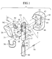
- Fig. 1 shows the structure of shift knob E1 of the shift lever of a transmission system according to the first embodiment of the invention.
- the shift knob is mounted to the upper end of the shift lever to operate the transmission mechanism of a vehicle.
- the shift knob has a knob button 20; a base 10 assembled to a mechanism M1 of a conversion means 30 which is worked by operation of knob button 20; a grip 40 removably mounted to base 10; and a cover 50 removably mounted to grip 40 to cover a gap between grip 40 and knob button 20.
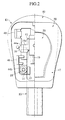
- the shift knob E1, though base 10, is attached to a shift lever 60.
- the operation of knob button 20 works through the conversion means 30, as a link lever in the embodiment, a compression rod 61 as a transmission member located slidably in a shift lever 60.
- the base 10 is configured in tube to allow shift lever 60 to be inserted therein.
- the shift lever From the upper to intermediate at the front, the shift lever has an assembly part 11 to allow the assembly of mechanism M1, including a link lever 30.
- Assembly part 11 has opposed shaft mounting parts 12 on both the left and right of the upper portion thereof, to allow the rotatable mounting link lever 30 by means of a pin 16.
- Assembly part 11 has opposed shaft mounting parts provided on both the sides of the lower portion thereof, to allow the rotatable mounting of the base of knob button 20 by a pin 15.
- Projecting from the both the left and right sides of base 10 are mounting parts 14 for the removable mounting of the base 10 to grip 40.
- Knob button 20 has shaft support holes 21 on both the left and right sides of its base. Between the left and right support holes 21, the left and right mounting parts 13 of base 10 are interposed, being mounted by pin 15. Between left and right mounting parts 13 and the base of knob button 20, a leaf spring 24 as a biasing means 24 is to bias outwards the upper portion of knob button 20.
- a shaft support 22 projects from the inner face of the upper portion of knob button 20, which supports the upper arm 31 of link lever 30, or conversion means, by pin 35.
- the shaft support 22 is formed in an elongated hole in the second embodiment as will be detailed later.
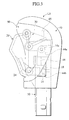
- knob button 20 causes the rotation of link lever 30 about shaft support 33 (mounted to the shaft support 12 of base 10), pin 35, which is inserted in the shaft support 34 of an upper arm 31, moves in a shaft support hole 23 as indicated in Fig. 4.
- Link lever 30 has an upper arm 31 and an operation arm 32 joined with each other, which are configured in L-shape.
- the crossing part has shaft support 33, which is interposed between the left and right shaft mounting parts 12 of base 10 and mounted by pin 16.
- Upper arm 31 has at its outer end an shaft support 34 connected by pin 35 with an elongated hole formed to the shaft support of knob button 20.
- the bottom face of operation arm 32 is to be brought in contact with a head 62 of compression rod 61.
- the operation of knob button 20 causes the smooth operation of compression rod 61 by means of link lever 30.
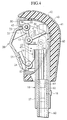
- Grip 40 is constituted with a grip body 41, and a surface cover 42 covering the outer surface of grip body 41 (alternatively, it may be constituted with only a grip body 41).
- the front side faces of grip body 41 are largely made open.
- the opening 43 allows base 10 assembled with a mechanism M1 such as knob button 20 and link lever 30 to be inserted therein, thus achieving removable mounting.
- the first embodiment has a plurality of mounting parts 44 as a mounting means provided directly to the inner face of the rear of grip body 41.
- Mounting parts 44 each define a threaded hole, which is fastened with a screw 18 as a fastening means through a hole formed to mounting part 14 of base 10.
- the lower part of grip body 41 defines a lower opening 46 which communicates with opening 43.
- An insertion part 17 in the lower portion of base 10 is, in turn, inserted into lower opening 46 via opening 43.
- a screw 18 fastens insertion part 17 of base 10 to the upper end of shift lever 60, being screwed into the threaded hole of shift lever 60 through the hole of insertion part 17.
- opening 43 has mounting parts 44 fixed separately therein for the attachment of base 10.
- Mounting parts 44 each include a cover locking part 48 for the locking of cover 50; and an upper mounting part 44a and lower mounting part 44b for mounting base 10.
- Upper mounting part 44a is formed with mounting holes facing sideways , for base 10 to be screwed to grip body 41 from both the sides by screws 18 as a fastening means.
- an upper mounting part 14a also faces sideways.
- leaf spring 24 as a biasing means are mounted to a spring holding part 19 in base 10 as shown in Figs. 5 and 6 and a spring holding part 25 at knob button 20, allowing the top of knob button 20 to be biased outwards.
- spring holding part 19 in base 10 includes a pair of L-shaped spring locking parts 19a which project from the outer face of base 10 extend along the axis of the base; a projection 19b which projects from the bottom face of the space between spring locking parts 19a i.e. the surface of base 10 and extends along the axis of the base; bent parts 19d which extend along insertion inner faces of locking parts 19a respectively.
- Spring holding part 25 of knob button 20 has an identical structure.
- Leaf spring 24 is mounted spring holding part 19 of base 10 and to spring holding part 25 of the knob button by gentle pushing, thus allowing the upper portion of knob button 20 to be biased outwards.
- grip body 41 of grip 40 is formed by a frame being molded from a hard synthetic resin beforehand and the frame as a core then being insert molded using a soft synthetic resin.
- grip 40 becomes soft to touch, improving the drive experience.
- the outer surface of produced grip body 41 further has a leather surface cover 42, which completes grip 40.
- a cut 63 in the upper end of shift lever 60 is employed for positioning and prevention of rotation of the knob upon insertion.
- Base 10 has a projection that engages with cut 63 in its insertion part 17.
- cover locking part 48 and mounting part 44 with upper and lower mounting parts 44a and 44b, being separately formed, are fixed within grip 40.
- grip 40 is molded from a material with good formability such as a synthetic resin
- the integral formation of these is preferable.
- the separate formation of cover locking part 48 and mounting part 44 are preferable to reduce in production costs.
- knob button 20 biasing means 24 for biasing knob button 20 to project outwardly from opening 43 of grip 40, and conversion means 30 for converting the pushing operation of knob button 20 into the axial movement of the compression rod constitute mechanism M1 that is attached to assembly part 11 of base 10, the structure of which improves the mechanism M1 in assembly operability.
- Knob button 20 located projecting from opening 43 of grip 40 and the inner surface of opening 43 define a space 47 therebetween.
- a fastening means of screw 18 of the embodiment fastens mounting part 14 of base 10 to the mounting means of grip body 41 in opening 43. Thereby, assembly ability and exchange operation of grip 40 are improved.
- knob button 20 projecting from opening 43 of grip 40 and provided with cover 50 to cover space 47 between knob button 20 and opening 43 of grip 40 reliably prevent any extraneous material from invading grip 40 or base 10 assembled with mechanism M1, and, on the other hand, keep the assembled parts from being visible from the outside, thus improving and beautifying the appearance.
- composing grip body 41 of only a mounting part 44 for mounting base 10 and a cover locking part 48 simplifies its structure. Thus, manufacture is facilitated even when Aluminum or a wood in addition to a resin are used.
- mounting part 44 for the mounting of base 10 further simplifies the structure of grip body 41, thus being preferable for the manufacturing process when using aluminum or wood.
Landscapes
- Engineering & Computer Science (AREA)
- General Engineering & Computer Science (AREA)
- Mechanical Engineering (AREA)
- Physics & Mathematics (AREA)
- General Physics & Mathematics (AREA)
- Automation & Control Theory (AREA)
- Arrangement Or Mounting Of Control Devices For Change-Speed Gearing (AREA)
- Control Of Transmission Device (AREA)
Applications Claiming Priority (2)
| Application Number | Priority Date | Filing Date | Title |
|---|---|---|---|
| JP2000192773A JP2002002321A (ja) | 2000-06-27 | 2000-06-27 | シフトレバー装置のシフトノブ構造 |
| JP2000192773 | 2000-06-27 |
Publications (2)
| Publication Number | Publication Date |
|---|---|
| EP1170655A2 true EP1170655A2 (de) | 2002-01-09 |
| EP1170655A3 EP1170655A3 (de) | 2002-11-20 |
Family
ID=18691857
Family Applications (1)
| Application Number | Title | Priority Date | Filing Date |
|---|---|---|---|
| EP01305438A Withdrawn EP1170655A3 (de) | 2000-06-27 | 2001-06-22 | Schaltungseinrichtung für ein Übertragungssystem |
Country Status (3)
| Country | Link |
|---|---|
| US (1) | US6732608B2 (de) |
| EP (1) | EP1170655A3 (de) |
| JP (1) | JP2002002321A (de) |
Cited By (6)
| Publication number | Priority date | Publication date | Assignee | Title |
|---|---|---|---|---|
| WO2003048611A1 (de) * | 2001-12-03 | 2003-06-12 | ZF Lemförder Metallwaren AG | Schaltknauf |
| EP1333197A1 (de) * | 2002-01-24 | 2003-08-06 | Ford Global Technologies, Inc., A subsidiary of Ford Motor Company | Wählhebel für ein Kraftfahrzeuggetriebe |
| CN102328587A (zh) * | 2010-06-30 | 2012-01-25 | 富士机工株式会社 | 用于汽车换档杆装置的换档把手附接结构 |
| EP3184859A1 (de) * | 2015-12-25 | 2017-06-28 | Kabushiki Kaisha Tokai-Rika-Denki-Seisakusho | Schalthebelvorrichtung |
| CN103821922B (zh) * | 2012-11-16 | 2017-12-15 | 德鱼塔工业股份有限公司 | 变速杆用把手的组装结构 |
| CN109890644A (zh) * | 2016-11-10 | 2019-06-14 | 株式会社东海理化电机制作所 | 换挡装置 |
Families Citing this family (17)
| Publication number | Priority date | Publication date | Assignee | Title |
|---|---|---|---|---|
| JP4101703B2 (ja) | 2003-06-11 | 2008-06-18 | 富士機工株式会社 | シフトレバー装置 |
| JP4384539B2 (ja) | 2004-05-06 | 2009-12-16 | 株式会社東海理化電機製作所 | シフトレバー |
| JP2006051862A (ja) | 2004-08-10 | 2006-02-23 | Tokai Rika Co Ltd | シフトレバー |
| JP2009018601A (ja) * | 2007-07-10 | 2009-01-29 | Atsumi Tec:Kk | 車両用変速操作装置 |
| US20090301249A1 (en) * | 2008-06-04 | 2009-12-10 | Timothy Smith | Automobile Gear Shifter Kit |
| JP2010052673A (ja) * | 2008-08-29 | 2010-03-11 | Fuji Kiko Co Ltd | シフトレバー装置 |
| JP5086390B2 (ja) * | 2010-05-10 | 2012-11-28 | 株式会社東海理化電機製作所 | シフトレバー |
| JP5475567B2 (ja) * | 2010-06-17 | 2014-04-16 | 株式会社東海理化電機製作所 | シフトレバー |
| KR101519272B1 (ko) * | 2013-12-20 | 2015-05-11 | 기아자동차주식회사 | 탑 힌지 버튼 타입 오토 노브 |
| JP6148712B2 (ja) * | 2015-11-05 | 2017-06-14 | 株式会社東海理化電機製作所 | シフト装置 |
| KR101664753B1 (ko) * | 2015-12-30 | 2016-10-12 | 현대자동차주식회사 | 변속 노브 조립체 |
| USD789264S1 (en) * | 2016-01-21 | 2017-06-13 | Pilot, Inc. | Shift knob cover |
| USD789263S1 (en) * | 2016-01-21 | 2017-06-13 | Pilot, Inc. | Shift knob cover |
| USD779401S1 (en) * | 2016-01-21 | 2017-02-21 | Pilot, Inc. | Shift knob cover |
| KR102443027B1 (ko) | 2018-03-02 | 2022-09-14 | 삼성전자주식회사 | 반도체 발광소자 |
| CN114893560A (zh) * | 2022-03-04 | 2022-08-12 | 汉喜龙汽车零部件(上海)有限公司 | 一种汽车换挡手球 |
| USD1074373S1 (en) * | 2024-02-08 | 2025-05-13 | Elesa S.P.A. | Handgrip for machine elements |
Citations (1)
| Publication number | Priority date | Publication date | Assignee | Title |
|---|---|---|---|---|
| JP2000192773A (ja) | 1998-12-25 | 2000-07-11 | Mitsui Constr Co Ltd | バックフィルシ―ルド掘進機 |
Family Cites Families (22)
| Publication number | Priority date | Publication date | Assignee | Title |
|---|---|---|---|---|
| US3998109A (en) * | 1975-09-15 | 1976-12-21 | General Motors Corporation | Automatic transmission control linkage |
| JPS57166220A (en) | 1981-04-01 | 1982-10-13 | Aihou Tekko Kk | Conveyance equipment |
| US4795296A (en) * | 1986-11-17 | 1989-01-03 | California Institute Of Technology | Hand-held robot end effector controller having movement and force control |
| US4774850A (en) * | 1987-08-24 | 1988-10-04 | Regal Plastics Company | Gear shifter cartridge |
| JP2802938B2 (ja) | 1989-06-05 | 1998-09-24 | 富士通テン 株式会社 | ワイパ制御装置 |
| US5207740A (en) * | 1990-05-30 | 1993-05-04 | Fujikiko Kabushiki Kaisha | Control device for automatic transmission |
| JPH05215205A (ja) | 1992-01-31 | 1993-08-24 | Suzuki Motor Corp | 車両用のコントロールノブ |
| JPH06174061A (ja) * | 1992-12-14 | 1994-06-21 | Tsuda Kogyo Kk | 自動変速機用変速操作レバー |
| JP3449763B2 (ja) * | 1993-11-30 | 2003-09-22 | 富士機工株式会社 | シフトレバー装置 |
| DE4427695A1 (de) * | 1994-08-04 | 1996-02-08 | Bayerische Motoren Werke Ag | Wählhebel für ein Kraftfahrzeuggetriebe |
| DE4434135A1 (de) * | 1994-09-24 | 1996-03-28 | Bayerische Motoren Werke Ag | Schalthebel für ein Kraftfahrzeuggetriebe |
| US5596894A (en) * | 1995-01-13 | 1997-01-28 | Lee; Chi-Yuan | Lock structure for the automatic shift lever of a car |
| DE19513809C1 (de) * | 1995-04-12 | 1996-10-31 | Lemfoerder Metallwaren Ag | Schalthebel für ein Automatikgetriebe in einem Kraftfahrzeug |
| JPH09183315A (ja) | 1995-12-29 | 1997-07-15 | Delta Kogyo Co Ltd | 自動車用チェンジレバーのノブ取り付け構造 |
| JP4104179B2 (ja) * | 1996-02-20 | 2008-06-18 | アルプス電気株式会社 | 車両用ノブスイッチ |
| CZ292103B6 (cs) * | 1997-07-11 | 2003-07-16 | Hkr Haas Gmbh & Co. Kunststoff Kg | Volicí páka pro automatickou převodovku |
| JPH11151944A (ja) * | 1997-11-21 | 1999-06-08 | Toyota Motor Corp | 操作レバー装置 |
| US6189398B1 (en) * | 1998-02-27 | 2001-02-20 | Fuji Koko Co., Ltd. | Shift-lever devices |
| DE19829173B4 (de) * | 1998-06-30 | 2005-04-28 | Zf Lemfoerder Metallwaren Ag | Schalthebel mit Sperrstange |
| US6131425A (en) * | 1998-08-27 | 2000-10-17 | Li; Chi-Yuan | Automatic shift lever knob with an imbedded lock |
| JP2000108706A (ja) * | 1998-10-05 | 2000-04-18 | Tokai Rika Co Ltd | シフトレバー装置 |
| DE19941795C1 (de) * | 1999-09-02 | 2001-01-18 | United Parts Fhs Automobil Sys | Automatikschaltgriff mit Druckmechanismus |
-
2000
- 2000-06-27 JP JP2000192773A patent/JP2002002321A/ja active Pending
-
2001
- 2001-06-22 EP EP01305438A patent/EP1170655A3/de not_active Withdrawn
- 2001-06-26 US US09/892,183 patent/US6732608B2/en not_active Expired - Fee Related
Patent Citations (1)
| Publication number | Priority date | Publication date | Assignee | Title |
|---|---|---|---|---|
| JP2000192773A (ja) | 1998-12-25 | 2000-07-11 | Mitsui Constr Co Ltd | バックフィルシ―ルド掘進機 |
Cited By (9)
| Publication number | Priority date | Publication date | Assignee | Title |
|---|---|---|---|---|
| WO2003048611A1 (de) * | 2001-12-03 | 2003-06-12 | ZF Lemförder Metallwaren AG | Schaltknauf |
| US7272988B2 (en) | 2001-12-03 | 2007-09-25 | ZF Lemförder Metallwaren AG | Shift knob |
| EP1333197A1 (de) * | 2002-01-24 | 2003-08-06 | Ford Global Technologies, Inc., A subsidiary of Ford Motor Company | Wählhebel für ein Kraftfahrzeuggetriebe |
| CN102328587A (zh) * | 2010-06-30 | 2012-01-25 | 富士机工株式会社 | 用于汽车换档杆装置的换档把手附接结构 |
| CN102328587B (zh) * | 2010-06-30 | 2014-05-07 | 富士机工株式会社 | 用于汽车换档杆装置的换档把手附接结构 |
| CN103821922B (zh) * | 2012-11-16 | 2017-12-15 | 德鱼塔工业股份有限公司 | 变速杆用把手的组装结构 |
| EP3184859A1 (de) * | 2015-12-25 | 2017-06-28 | Kabushiki Kaisha Tokai-Rika-Denki-Seisakusho | Schalthebelvorrichtung |
| CN109890644A (zh) * | 2016-11-10 | 2019-06-14 | 株式会社东海理化电机制作所 | 换挡装置 |
| CN109890644B (zh) * | 2016-11-10 | 2022-03-04 | 株式会社东海理化电机制作所 | 换挡装置 |
Also Published As
| Publication number | Publication date |
|---|---|
| US20020062709A1 (en) | 2002-05-30 |
| US6732608B2 (en) | 2004-05-11 |
| JP2002002321A (ja) | 2002-01-09 |
| EP1170655A3 (de) | 2002-11-20 |
Similar Documents
| Publication | Publication Date | Title |
|---|---|---|
| US6732608B2 (en) | Shift knob and shift lever | |
| US6025565A (en) | Lever switch for vehicles | |
| US4873884A (en) | Apparatus for supporting shift lever for transmission | |
| JP6204192B2 (ja) | スナップ固定式ドアハンドルとロックノブとの組立体 | |
| JP5513442B2 (ja) | 車両用ドアのアウトハンドル装置 | |
| JP2002093273A (ja) | 車両用ハンドルスイッチの取付構造 | |
| US20040155391A1 (en) | Motor vehicle equipment module | |
| JP2003151403A (ja) | スイッチ | |
| CA2370906C (en) | Deadbolt thumbturn assembly | |
| JPH10162694A (ja) | 車両用レバースイッチの構造 | |
| KR100242773B1 (ko) | 카 오디오용 컨트롤 패널의 결합구조 | |
| US20020070597A1 (en) | Chair adjustment device | |
| JP3385349B2 (ja) | 変速機用シフトレバー装置 | |
| US20050272284A1 (en) | Interconnected chassis for a lock set | |
| JPH0623656Y2 (ja) | 自動車用ドアハンドル装置 | |
| KR100532045B1 (ko) | 자동차용 자동온도조절장치의 스위치캡 조립구조 | |
| JPH07259973A (ja) | 自動変速機の変速操作装置 | |
| JP2579542Y2 (ja) | 複合スイッチの構造 | |
| DE102023130330A1 (de) | Reziprowerkzeug | |
| JP2001032579A (ja) | アウトサイドドアハンドルの取付構造 | |
| JPH11348737A (ja) | ワイパー付き車両用ミラー | |
| KR200349579Y1 (ko) | 도어락장치의 고정패널 | |
| JPH06321160A (ja) | 自動二輪車のハンドルスイッチ取付構造 | |
| JPS625480Y2 (de) | ||
| JP2024155614A (ja) | シフト装置 |
Legal Events
| Date | Code | Title | Description |
|---|---|---|---|
| PUAI | Public reference made under article 153(3) epc to a published international application that has entered the european phase |
Free format text: ORIGINAL CODE: 0009012 |
|
| AK | Designated contracting states |
Kind code of ref document: A2 Designated state(s): AT BE CH CY DE DK ES FI FR GB GR IE IT LI LU MC NL PT SE TR |
|
| AX | Request for extension of the european patent |
Free format text: AL;LT;LV;MK;RO;SI |
|
| PUAL | Search report despatched |
Free format text: ORIGINAL CODE: 0009013 |
|
| AK | Designated contracting states |
Kind code of ref document: A3 Designated state(s): AT BE CH CY DE DK ES FI FR GB GR IE IT LI LU MC NL PT SE TR |
|
| AX | Request for extension of the european patent |
Free format text: AL;LT;LV;MK;RO;SI |
|
| RIC1 | Information provided on ipc code assigned before grant |
Free format text: 7G 05G 1/06 A, 7F 16H 59/04 B |
|
| 17P | Request for examination filed |
Effective date: 20030121 |
|
| AKX | Designation fees paid |
Designated state(s): DE GB SE |
|
| STAA | Information on the status of an ep patent application or granted ep patent |
Free format text: STATUS: THE APPLICATION IS DEEMED TO BE WITHDRAWN |
|
| 18D | Application deemed to be withdrawn |
Effective date: 20060503 |