EP1130549A2 - Appareil automatique de barrière à ouverture à l'aide d'un ticket - Google Patents
Appareil automatique de barrière à ouverture à l'aide d'un ticket Download PDFInfo
- Publication number
- EP1130549A2 EP1130549A2 EP01300958A EP01300958A EP1130549A2 EP 1130549 A2 EP1130549 A2 EP 1130549A2 EP 01300958 A EP01300958 A EP 01300958A EP 01300958 A EP01300958 A EP 01300958A EP 1130549 A2 EP1130549 A2 EP 1130549A2
- Authority
- EP
- European Patent Office
- Prior art keywords
- ticket
- magnetic
- wireless
- passage
- main body
- Prior art date
- Legal status (The legal status is an assumption and is not a legal conclusion. Google has not performed a legal analysis and makes no representation as to the accuracy of the status listed.)
- Withdrawn
Links
Images


Classifications
-
- G—PHYSICS
- G07—CHECKING-DEVICES
- G07B—TICKET-ISSUING APPARATUS; FARE-REGISTERING APPARATUS; FRANKING APPARATUS
- G07B15/00—Arrangements or apparatus for collecting fares, tolls or entrance fees at one or more control points
- G07B15/02—Arrangements or apparatus for collecting fares, tolls or entrance fees at one or more control points taking into account a variable factor such as distance or time, e.g. for passenger transport, parking systems or car rental systems
- G07B15/04—Arrangements or apparatus for collecting fares, tolls or entrance fees at one or more control points taking into account a variable factor such as distance or time, e.g. for passenger transport, parking systems or car rental systems comprising devices to free a barrier, turnstile, or the like
-
- G—PHYSICS
- G07—CHECKING-DEVICES
- G07C—TIME OR ATTENDANCE REGISTERS; REGISTERING OR INDICATING THE WORKING OF MACHINES; GENERATING RANDOM NUMBERS; VOTING OR LOTTERY APPARATUS; ARRANGEMENTS, SYSTEMS OR APPARATUS FOR CHECKING NOT PROVIDED FOR ELSEWHERE
- G07C9/00—Individual registration on entry or exit
- G07C9/10—Movable barriers with registering means
Definitions
- the present invention relates to an automatic ticket gate apparatus, which are installed at entrance and exit gates of stations and a like of transportation facilities including railways.
- automatic ticket gate apparatus are installed at stations of transportation facilities including railways.
- the automatic ticket gate apparatus receive and transfer the magnetic tickets inserted by users and read out information magnetically recorded on tickets and return the tickets at the take-off port in the forwarding side of the apparatus.
- Propriety of passage (entrance to station premises or exit from station premises) of users is judges and when the passage in permitted, a gate is opened to allow passage. When passage is not permitted, the gate is closed to prevent the passage of the user. Also, guidance such as cautions is displayed at a display panel mounted on the top cover of apparatus, or outputted by a speaker.
- this kind of automatic ticket gate apparatus are provided with a wireless communication function and execute similar judgement of passage for wireless ticket and controls the passage of users.
- An object of the present invention is to reduce the space for installing automatic ticket gate apparatus sharply and to provide automatic ticket gate apparatus that can prevent erroneous presentation of a wireless ticket to ticket gate apparatus.
- automatic ticket gate apparatus comprising a main body defining a passage for ticket checking; a wireless communicating face inclined from horizontal toward the passage, which is provided on the top of the main body and which is provided with a wireless communicator which communicates with a wireless ticket carried by a passenger passing the passage; and ticket checking means for checking ticket information communicated with the wireless ticket through the wireless communicator, the wireless ticket being carried by the passenger.
- the tickets that are processed by the ticket gate apparatus of the present invention are magnetic tickets and wireless tickets. Furthermore, magnetic tickets are limited to one size. Wireless tickets shall cover the tickets of different sizes from the magnetic tickets that are limited to one size.
- magnetic tickets which shall be processed by the automatic ticket gate apparatus of the present invention, shall be limited to Edomondson size (57.5 mm ⁇ 30 mm). Furthermore, the magnetic tickets, which are to be processed by the apparatus, shall be limited to the tickets available only in the issued date as the tickets for a certain short distance. In the other words, the magnetic tickets shall be limited to the normal tickets only.
- season-tickets which allow the transportation in a certain period and for a certain section (57.5 mm ⁇ 85 mm)
- prepaid ticket such as Stored Fare Tickets, which allow the transportation against the information regarding the sum of money registered in the ticket in advance
- tickets for long distance Long distance tickets
- the volume of the data can be limited by limiting the kinds of the magnetic tickets (by limiting the use to the normal tickets only), and therefore the volume of the data to be recorded in the magnetic tickets can be limited, and as the result, the size of the magnetic tickets can be also unified to Edomondson size only.
- magnetic tickets can be unified to the Edomondson size only by changing the recording system. For example, FM-System, which is of high recording density and does not require CP truck (Clock Pulse), can be adopted, while NRZ 1 System (Non return to zero one), which is of low recording density, is abandoned. Even in the case of magnetic tickets of Edomondson size, relatively large volume of data can be stored. As the result, long distance tickets involving the information of the super express ticket can be issued as magnetic tickets of Edomondson size.
- Fig.1 is a perspective illustration showing the outline of outlook of an automatic ticket gate apparatus in accordance with the present invention.
- Fig.2 is a drawing showing top view, side view and elevational view of the automatic ticket gate apparatus in accordance with the present invention.
- Fig.3 is a sectional drawing showing the outline of the inside construction of the automatic ticket gate apparatus of the present invention.
- an automatic ticket gate apparatus comprises a main controller 1, a control panel for maintenance 2, a power source unit 3, a door 4, a human monitoring sensor unit 5, a speaker 6, a ticket collector 7, a ticket checking processor 10a, and a ticket collecting processor 10b and a like.
- the main controller 1 performs the control of the whole automatic ticket gate apparatus.
- the control panel for maintenance 2 is the panel, which is operated by the staff-member in charge of maintenance of the automatic ticket gate apparatus.
- the power source unit 3 supplies with current to the respective parts of the automatic ticket gate apparatus.
- the door 4 closes the passage by closing the door.
- the door 4 is driven by the door opening/closing drive 4a.
- the human monitoring sensor unit 5 is to detect the user, who passes on the side of the automatic ticket gate apparatus, in other words, the users who pass through the ticket checking passage.
- the speaker 6 is to output various information to the users.
- the ticket collector 7 is equipped with a collecting box, in which used magnetic tickets are collected.
- the ticket checking processor 10a comprises a processor.
- the ticket checking processor 10a comprises a passage display 12a, an insert port 14a, a fare adjustment key 15a, a wireless communicator 16a, a guidance display 18a, a checking result display 20a, a take-out port 22a and a conveying mechanism 24a.
- the passage display 12a indicates various guidance to the user, who passes through the passage along the automatic ticket gate apparatus.
- the insert port 14a is to receive the magnetic ticket inserted by the user.
- the fare adjustment key 15a is to instruct a fare adjustment to the main body of the apparatus, when a fare adjustment is required.
- the wireless communicator 16a is to communicate with the wireless tickets, which is held up by users, to receive the data sent by the wireless ticket or to send data to the wireless tickets.
- the guidance display 18a is to display various guidance to the users.
- the checking result indicating display 20a is to indicate the checking result. For example, when the passage is allowed, a blue lamp lights up and when the passage is rejected, a red lamp lights up. Furthermore, the checking result indicating display 20a may be equipped with a display by means of letters.
- the ticket take-out port 22a is to deliver the magnetic ticket that has been received at the insert port 14a. In other words, the magnetic ticket is returned to the user.
- the conveying mechanism 24a is to transfer the magnetic ticket that is received at the insert port 14a to the take-out port 22a.
- the ticket collecting processor 10b comprises a processor.
- the ticket collecting processor 10b comprises a passage display 12b, an insert port 14b, a fare adjustment key 15b, a wireless communicator 16b, a guidance display 18b, a checking result display 20b, a take-out port 22b and a conveying mechanism 24b.
- the passage display 12b indicates various guidance to the user, who passes through the passage along the automatic ticket gate apparatus.
- the insert port 14b is to receive the magnetic ticket inserted by the user.
- the fare adjustment key 15b is to instruct a fare adjustment to the main body of the apparatus, when a fare adjustment is required.
- the wireless communicator 16b is to communicate with the wireless tickets, which is held up by users, to receive the data sent by the wireless ticket or to send data to the wireless tickets.
- the guidance display 18b is to display various guidance to the users.
- the checking result indicating display 20b is to indicate the checking result. For example, when the passage is allowed, a blue lamp lights up and when the passage is rejected, a red lamp lights up. Furthermore, the checking result indicating display 20b may be equipped with a display by means of letters.
- the ticket take-out port 22b is to deliver the magnetic ticket that has been received at the insert port 14b. In other words, the magnetic ticket is returned to the user.
- the conveying mechanism 24b is to transfer the magnetic ticket that is received at the insert port 14b to the take-out port 22b, or to the ticket collector 7. Meantime, instead of providing a ticket take-out port 22b at the ticket collecting processor 10b, al the tickets received at the insert port 14b may be collected by the ticket collector 7.
- the conveying mechanism 24a provided as a part of the ticket checking processor 10a is covered by a top cover 26a.
- This top cover 26a is mounted on the automatic ticket gate apparatus allowing to be opened and closed freely.
- On the top cover 26b there are provided with an insert port 14a, a wireless communicator 16a, a guidance display 18a, a checking result indicating display 20a and a take-out port 22a.
- a top cover 26b covers the conveying mechanism 24b as a part of the ticket collecting processor 10b.
- This top cover 26b is mounted on the automatic ticket gate apparatus allowing to be opened and closed freely.
- On the top cover 26b there are provided an insert port 14b, a wireless communicator 16b, a guidance display 18b and a checking result indicating display 20b.
- the one top cover 26a is so composed that it can be opened toward the one side passage separated by the automatic ticket gate apparatus and the top cover 26b is so composed that it can be opened toward the other side passage separated by this automatic ticket gate apparatus.
- the main body of the said automatic ticket gate apparatus defines the ticket checking and collecting passage and the top covers 26a and 26 b are mounted on the box 10.
- the top cover 26a is provided with a wireless communicator 16a so that it functions as the communication face.
- the top cover 26b is also provided with a wireless communicator 16b and functions as a communicating face. These communicating faces are inclined from the horizontal toward the respective passages.
- the main body of the automatic ticket gate apparatus defines the first passage and the second passage for ticket checking and collecting and is installed between the both passages.
- the top cover 26a as a wireless communicating face is provided from one end almost to the center of the box 10 on the top, and is inclined from the horizontal toward the first passage.
- a ticket checking process is performed for the user who advances toward the first direction on the first passage from one end to the other end of the box 10 of the automatic ticket gate apparatus, basing upon the ticket data obtained from the wireless ticket through the wireless communicator 16a provided on the top cover 26a.
- the top cover 26b as the communicating face is provided from the other end almost to the center of the box 10 on the box and is inclined from the horizontal toward the second passage.
- a ticket checking process is performed for the person who advances reversibly toward the second direction on the second passage from the other end to one end of the box 10 of the automatic ticket gate apparatus, basing upon the ticket data obtained from the wireless ticket through the wireless communicator 16b provided on the top cover 26b.
- the users can hold up the wireless ticket to the wireless communicators 16a and 16b in a natural posture. Similarly, the users can confirm the content indicated in the guidance indicating displays 18a and 18b in natural posture.
- a checking result indicating display 20a On the side face supporting the inclination of the top cover 26b protruding against the top cover 26a, which functions as a communicating face, there is provided a checking result indicating display 20b.
- a checking result indicating display 20b On the side surface supporting the inclination of the top cover 26a protruding against the top cover 26b, which functions as a communicating face, there is provided a checking result indicating display 20b.
- the checking result indicating display 20b is provided on the protruding portion over the top cover 26b, an excellent visual recognition can be allowed.
- the checking result indicating display 20b is provided on the protruding portion of the top cover 26a an excellent visual recognition can be allowed.
- the checking result indicating display 20a protrudes over the top cover 26a, it can be protected that the wireless tickets held up to the wireless communicator 16a is held up to the wireless communicator 16b successively. In other words, the checking result indicating display 20a plays a role that it shelters the wireless ticket held up to the wireless communicator 16a.
- the checking result indicating display 20b protrudes over the top cover 26b, it can be protected that the wireless tickets held up to the wireless communicator 16b is held up to the wireless communicator 16a successively. In other words, the checking result indicating display 20b plays a role that it shelters the wireless ticket held up to the wireless communicator 16b.
- a magnetic ticket can be delivered at a delivery angle as shown in Fig.4A. That is, the magnetic ticket is received and transferred horizontally in the apparatus and at the same time the magnetic ticket is turned to the direction crossing to the communication face and transferred to meet the inclination of the communicating face. Also, a magnetic ticket can be delivered at a delivery angle shown in Fig.4B. In case of Fig.4A, the magnetic ticket is delivered, while a side of the ticket is kept parallel to the top cover as the communicating face.
- the magnetic ticket is delivered, while the side of the magnetic ticket crossing to the transfer direction is kept non-parallel to the top cover as the communicating face.
- the arrangement allows to have the user take out the magnetic ticket, without forcing the user to take an unnatural posture.
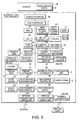
- Fig.5 is a block diagram showing the schematic constitution of the ticket gate apparatus in accordance with the present invention.
- a ticket gate apparatus of the present invention comprises a main controller 1, a ROM 30, a RAM 32, a fare memory 34, a reader/writer 36, a conveyer controller 38, a printer controller 40, a ticket sensor monitoring unit 42, a human sensor monitoring unit 44, a door opening/closing controller 46, a display controller 48, a punching controller 50, a holding controller 52, a top cover opening/closing monitor 54, a power source controller 56, a maintenance controlling panel controller 58, a mode changing switch 60, a wireless communication controller 62, as network communication controller 64, a monitor interface 66 and a like.
- the main controller 1 performs the whole control of the automatic ticket gate apparatus.
- the ROM 30 memories the control program for the main controller 1.
- the RAM 32 memories temporarily the data arising at the time of controlling the automatic ticket gate apparatus by the main controller.
- the fare memory 34 memories the data of the fares.
- the reader/writer 36 controls the magnetic head for reading and recording to read out the data stored magnetically in the magnetic ticket and record magnetically the specified data in the magnetic ticket.
- the conveyer controller 38 performs the control of the transfer of the magnetic ticket by the conveying mechanisms 24a and 24b. This conveyer controller 38 controls the shutters 37 provided at the insert ports 14a and 14b to prohibit the insertion of the magnetic ticket.
- the printer controller 40 controls the thermal head 39 to print the specified data in the magnetic ticket.
- the ticket monitoring sensor unit 42 checks the signals detected from a plurality of ticket sensors 41 provided along the conveying mechanism 24a and 24b and monitors the transfer situation of the magnetic ticket by the conveying mechanisms 24a and 24b.
- the human sensor monitoring unit 44 checks the human detecting signals from the human detecting sensor 5 to monitor the passerby along the automatic ticket gate apparatus.
- the door opening/closing controller 46 controls the drive for opening and closing the door 4.
- the display controller 48 controls the display of the various displays such as a passage display 12a, a guidance display 18a, a checking result indicating display 20a, a passage display 12b, a guidance display 18b, a checking result indicating display 20b and a like.
- the punching controller 50 controls the timing for punching and a like by the punching mechanism 49 provided at a certain position along the conveying mechanisms 24a and 24b.
- the holding controller 52 performs the holding of the magnetic ticket by the holding mechanism 51 provided at a certain position along the conveying mechanisms 24a and 24b.
- the top cover opening/closing monitor 54 checks the detecting signals from the top cover sensor 54a that detects the opening/closing state of the top cover 26a and from the top cover sensor 54b that detects the opening/closing state of the top cover 26b to monitor the opening/closing state of the top covers 26a and 26b.
- the power source controller performs the control of the power supply by the power source unit3.
- the maintenance controlling panel controller 58 performs the control of the automatic ticket gate apparatus basing upon the settings inputted by the control panel for maintenance 2.
- the maintenance controlling panel controller 58 performs also the switching subject for the maintenance by means of the control panel for maintenance. For example, in the state that the top cover 26a only is open (the opening/closing state of the top cover is monitored by the top cover opening/closing monitor 54, the maintenance controlling panel controller 58 switches the object for maintenance by the control panel for maintenance to the ticket collecting processor 10b. Furthermore, in the state that the both top covers 26a and 26b are open, the maintenance controlling panel controller 58 switches the object for maintenance by the control panel for maintenance 2 to the both ticket checking processors 10a and 10b.
- the mode-changing switch 60 switches the mode for the automatic ticket gate apparatus.
- a magnetic mode As the modes, a magnetic mode, a wireless mode and a combination mode are provided.
- the objects of the ticket checking process and the ticket collecting process becomes magnetic tickets only.
- the passage displays 12a and 12b indicate that the magnetic tickets only are objects of the process. In such a case, even effective wireless ticket is not allowed for the passage.
- the mode is switched to the wireless mode by means of mode-changing switch 60, the objects of ticket checking and collecting processes becomes wireless tickets only.
- the guidance displays 12a and 12b indicate that the wireless tickets only are the objects of the process.
- the insert port shutters provided at the insert ports 14a and 14b are closed so that magnetic ticket cannot be inserted into the insert ports 14a and 14b.
- the mode is switched to the combination mode by the mode changing switch 60, the object of the ticket processing and collecting process become both magnetic tickets and the wireless tickets.
- the passage displays 12a and 12b indicate that both magnetic tickets and wireless tickets are the object of the process.
- the wireless communication controller 62 performs the control of the receiving power of the wireless communicators 16a and 16b, the demodulation of the data received at the wireless communicators 16a and 16b and the modulation of the data to be transmitted from the wireless communicators 16a and 16b.
- the network communication controller 64 performs the control the communication with the outside network.
- the monitor interface functions as the interface between the monitor 66 installed outside and the automatic ticket gate apparatus. Also the monitor 66 is provided with a mode-changing switch 60. By the mode changing switch 60 provided in the monitor 66, the mode can be changed for each automatic ticket gate apparatus independently.
- a plurality of automatic ticket gate apparatus are installed on the boundary between the station premises and outside the station premises.
- the space between the respective automatic ticket gate apparatus are the common passages for ticket checking and ticket collecting process.
- the ticket gate apparatus provided either with a ticket checking processor or with a ticket collecting processor is installed.
- a user When a user receives a ticket checking process with a magnetic ticket, the user enters into the passage from outside the station premises and inserts a magnetic ticket into the insert port 14a.
- the inserted magnetic ticket is transferred by the conveying mechanism 24a, and the data stored in the magnetic ticket are read out by the magnetic head 35 for reader/writer on the way, and certain data are stored in the magnetic ticket as the case may be.
- the main controller 1 performs a judgement as to the propriety of passage basing upon the data read out from the magnetic ticket and the data stored in the fare memory 34.
- a puncher or a printer processes the magnetic ticket as the case may be, and is delivered at the take-out port 22a. In this case, the checking result indicating display 20a lights up blue.
- the magnetic ticket is delivered as it is at the take-out port 22a and at the same time, the passage of the user is prevented by closing the door 4. (The entrance into the station premises is prohibited.) In this case the checking result indicating display 20a lights up red.
- the user When a user receives the ticket checking process with wireless ticket, the user enters into the passage from the outside the station premises and holds up the wireless ticket to the wireless communicator 16a. Thereat, the data stored in the wireless ticket is read out by a communication between the wireless ticket and the wireless communicator 16a and certain data are written in the wireless ticket as the case may be.
- the main controller 1 performs a judgment as to the propriety of the passage basing upon the data read out from the wireless ticket and the data stored in the fare memory 34.
- the checking result indicating display 20a lights up blue.
- the passage of the user is prevented by closing the door 4. (The entrance into the station premises is prohibited.) In this case the checking result indicating display 20a lights up red.
- the user When a user receives a ticket collecting process with a magnetic ticket, the user enters from the inside station premises and inserts the magnetic ticket into the insert port 14b.
- the inserted magnetic ticket is transferred by the conveying mechanism 24b and the data stored in the magnetic ticket are read out by the magnetic head 35 for the reader/writer on the way.
- the main controller 1 performs a judgment as to the propriety of the passage basing upon the data read out from the magnetic ticket and the data stored in the fare memory 34.
- the magnetic ticket When the passage is permitted, the magnetic ticket is collected by the ticket collector 7. In this case, the checking result indicating display 20b lights up blue.
- the magnetic ticket is delivered at the take-out port 22b as it is and the passage of the user is prevented by closing the door 4. (The exit to outside the station premises is prohibited.) In this case, the checking result indicating display 20b lights up red.
- the main controller 1 performs a judgement as to the propriety of the passage basing upon the data read out from the wireless ticket and the data stored in the fare memory 34.
- the checking result indicating display 20b lights up blue.
- the passage of the user is prevented by closing the door 4. (The exit to outside the station premises is prohibited.) In this case the checking result indicating display 20b lights up red.
- the monitor 68 is informed of the machine number of the automatic ticket gate apparatus, at which passage is rejected.
- the location of the magnetic head 35 is described.
- One side of the magnetic ticket is a magnetic recording side, on which the magnetic information is stored and the other side is the printing side, on which information by means of letters is printed.
- the magnetic head 35 is located so that the magnetic ticket can be processed, in any case when the magnetic ticket is inserted with the magnetic recording side up or down.
- the first arrangement of the magnetic head 35 is described.
- a magnetic head 35 for the reader/writer is located along the conveying mechanism 24a and 24 b, for the case that a magnetic ticket is inserted with the magnetic recording side down.
- a magnetic head 35 for the reader/writer is located along the conveying mechanism 24a and 24b, for the case that magnetic ticket is inserted with the magnetic recording side up.
- both cases that the magnetic ticket is inserted with the magnetic recording side down or up can be dealt.
- the magnetic head 35 for the writer may be eliminated. (The magnetic head for the writer is not provided.) Especially, for it is not necessary to write data in the magnetic ticket.
- the magnetic recording side of the magnetic ticket to be collected at the ticket collector 7, may be destroyed by punching by the punching mechanism 49.
- the constitution of the machine can be simplified by eliminating the magnetic head 35 for the writer at the ticket collecting processor 10b.
- the second arrangement of the magnetic head is described.
- the magnetic head 35 for the writer is located along the conveying mechanism 24a and 24b for the case that a magnetic ticket is inserted with a magnetic recording side down.
- the magnetic head 35 for the writer is located along the conveying mechanism 24a and 24b for the case that a magnetic ticket is inserted with the magnetic recording side up.
- the magnetic head 35 for the tickets with the magnetic recording side down only is located along the conveying mechanism 24a and 24b.
- the magnetic tickets inserted with the magnetic recording side both down and up can be dealt. There is no problem, when the magnetic ticket is inserted with the magnetic recording side down.
- the output for the reading out the data becomes weak. This is due to the fact that the magnetic recording side becomes far from the magnetic head and the magnetic output becomes weak because of the influence of space loss. In this case the output current is lower than a specified value, the gain of the reading out amplifier is changed over, and the reading out can be realized by increasing the magnification of the output.
- the magnetic head 35 for the reader/write can be eliminated, same as in the case of the arrangement 1 of the magnetic head 35. (The magnetic head for the writer is not provided.)
- the magnetic recording side of the magnetic ticket to be collected by the ticket collector 7, may be destroyed by punching by the punching mechanism 49.
- the constitution of the machine can be simplified by eliminating the magnetic head for the writer at the ticket collecting processor.
- the ticket checking processor 10a of the present invention is provided with a take-out port 22a in the neighborhood of the center of the ticket checking and collecting passage. For this reason, there is a possibility that a wireless ticket user who has entered in the ticket collecting passage in advance, can take out erroneously the magnetic ticket of the next following user of the magnetic ticket, who comes after into the passage. Therefore, as explained in the following, it is necessary to control the timing to receive the next user.
- the passage through the ticket collecting passage is prevented by closing the door (ST16).
- the passage through the ticket collecting passage is permitted while the door is open (ST18).
- the passage state of the first user is recognized basing upon the output from the human sensor 5, and the timing for receiving the next user is controlled, basing upon the passage state of the first user. For example, until the first user reaches the center of No.1 machine (ST20 NO), the next user is not received at all (ST22). In other words, neither a magnetic ticket nor a wireless ticket of the next user is received. Accordingly, the insertion of the magnetic ticket into the insert port 12a is prohibited, while the shutter 37 of the ticket insert port 12a is closed. In this case, the guidance for the entrance prohibition is displayed at the passage display 12a.
- the magnetic ticket of the next user is not received (ST28).
- the receipt of the magnetic ticket of the next user is permitted (ST30). At this moment, the shutter 37 is opened and the insertion of the magnetic ticket into the insert port 12a is permitted.
- next user is the user of the wireless ticket
- the receipt of the ticket is permitted earlier than the case that the next user is the user of the magnetic ticket. This is due to the fact that the foregoing user never takes out erroneously the ticket of the next user erroneously, when the next user is a user of a wireless ticket. Therefore, at the timing that the necessary data are dispatched to the wireless ticket and the recording is finished, after the wireless communication is made with the wireless ticket of the foregoing user and a judgment for the passage is made, the receipt of the wireless ticket of the next user is permitted.
- the next user is the user of a magnetic ticket
- the receipt of the ticket is permitted, after it is detected that the foregoing user (the user of the wireless ticket) has passed through the center of the automatic ticket gate apparatus and has reached to the exit.
- the utilization efficiency of the automatic ticket gate apparatus is increased.
- the utilization efficiency can be increased by operating the automatic ticket gate apparatus in a changed mode as follows.
- the automatic ticket gate apparatus is provided with a mode changing switch 60.
- the monitor 68 is provided with a mode-changing switch 68.
- the mode-changing switch provided in the monitor 68 could change the mode of each machine.
- This mode changing switch 60 changes the mode among a exclusive magnetic ticket mode, an exclusive wireless ticket mode and a combination mode.
- the object of the ticket checking and collecting processors of the automatic ticket gate apparatus become only magnetic tickets. In this case, it is displayed on the displays 12a and 12b, that the magnetic tickets only are the objects of the process. In such a case, even with an effective wireless ticket, the passage is not permitted.
- the operation mode is changed to the exclusive wireless mode by the mode-changing switch 60
- the object of the ticket checking and collecting process by the automatic ticket gate apparatus becomes only wireless ticket. In this case, it is displayed on the passage displays 12a and 12b, that the wireless tickets only are the objects of the process. In this case, the passage is not permitted even with an affective wireless ticket.
- the objects of the ticket checking and collecting processors become wireless tickets only.
- the passage displays 12a and 12b display that wireless tickets only are the objects of the process. Furthermore, the shutters of the ticket insert ports 14a and 14b are closed, and the magnetic tickets cannot be inserted.
- the object of the ticket checking and collection processors becomes both magnetic tickets and wireless tickets. In this case, it is displayed on the passage displays 12a and 12b that both magnetic tickets and wireless tickets are object of the processing.
- a station is assumed where a plurality of automatic ticket gate apparatus are provided and a plurality of the passages for ticket checking and collecting are provided.
- the automatic ticket gate apparatus are operated in the exclusive wireless mode.
- the remaining automatic ticket gate apparatus are operated in the exclusive magnetic ticket mode or in the combination mode.
- the users are pass users. In the operation of this automatic ticket gate apparatus, all the passes are allocated to the wireless tickets.
- the processing efficiency per a automatic ticket gate apparatus can be increased, so that as the result, the crowdedness of the ticket processing can be relieved.
- the processing efficiency of the ticket checking and collecting process can be increased.
- the automatic ticket gate apparatus of the present invention are able to handle both magnetic tickets and wireless tickets. Therefore, the automatic ticket gate apparatus are provided with a processor for handling magnetic tickets and a processor for handling wireless tickets.
- the apparatus can be operated by changing operating mode as described in the above. The changing of the operating mode can be executed by a maintenance staff-member, or can be performed automatically by the machine itself by detecting the trouble situation.
- the automatic ticket gate apparatus are provided with a fare adjustment keys 15a and 15b and the adjustment of the fare becomes possible by pushing down the adjustment key 15a.
- the timing for the pushing down the adjustment key 15a may be either before the first ticket is processed or after the said ticket is processed.
- the guidance displays 18a and 18b are designed as touch panels so that the adjustment keys may be displayed on the guidance displays 18a and 18b.
- the automatic ticket gate apparatus not provided with an adjustment key, but to have the said mechanism to judge the propriety of the fare adjustment and to request fare adjustment.
- the automatic ticket gate apparatus receives both a magnetic ticket and a wireless ticket (ST40), the fare adjustment key 15a or 15b is pushed down (ST42, YES).
- ST40 the fare adjustment key 15a or 15b is pushed down
- ST42 YES
- the fare adjustment key 15a or 15 b is pushed down before the ticket is received.
- the user has not another magnetic ticket or another wireless ticket, he may not execute fare adjustment.
- the next magnetic ticket or the wireless ticket is requested for the fare adjustment (ST50).
- the guidance such as "a magnetic ticket should be inserted into the insert port or "a wireless ticket shall be held to the wireless communicator" is displayed on the guidance display 18a or 18b.
- this first magnetic ticket is held at the holding mechanism 51 and is subject to a combined judgment and a fare adjustment.
- the passage is permitted (ST58). Also, when either one of the first ticket and the second ticket is a ticket, with which fare adjustment is allowed (such as SF card in which the sum for fare adjustment is not short), the fare adjustment is performed and then the passage is permitted (ST58). Also, in case of the above combined judgement or fare adjustment, the ticket is recorded with a specified data. When the combined judgment is negative and the fare adjustment cannot be performed (ST56, NO), the door is closed and the passage is prohibited (ST60).
- the automatic ticket gate apparatus receives both a magnetic ticket and a wireless ticket (ST40), either the magnetic ticket or the wireless ticket is received, without pressing the fare adjustment key 15a or 15b (ST42, NO) down, the passage checking process is performed basing upon the received ticket (ST 64).
- the checking result is acceptable (OK) (ST64, YES)
- the passage is permitted (ST 58).
- the checking result is negative (NG)
- the passage is prohibited by closing the door and the guidance indicating display 18a or 18b indicates the guidance such as "Please push down the fare adjustment key, when the fare adjustment is requested", and a like.
- the process is finished while the passage is prohibited (ST60).
- the first ticket is a magnetic ticket
- this magnetic ticket is returned.
- the guidance display indicates a guidance such as " Please insert a magnetic ticket into the insert port or hold up a wireless ticket to the wireless communicator" and a like.
- the first ticket is a magnetic ticket
- this magnetic ticket is held at the holding mechanism 51, and the combined judgment and the fare adjustment shall be awaited.
- the passage is permitted (ST58).
- ticket is an adjustable ticket (a ticket such as SF card, which is not short of the sum for fare adjustment)
- the fare adjustment is performed and the passage is permitted (ST58).
- a specified data is recorded in the ticket as the case may be.
- the door is closed and the passage is prohibited (ST 60).
- the space for the installation can be reduced remarkably, and the ticket gate apparatus, which is able to perform the ticket checking process easily (easy to hold up the wireless ticket to the wireless communicator, easy to recognize the checking result indicating display, easy to take out the delivered magnetic ticket and so on), can be provided.
Landscapes
- Physics & Mathematics (AREA)
- General Physics & Mathematics (AREA)
- Business, Economics & Management (AREA)
- Finance (AREA)
- Devices For Checking Fares Or Tickets At Control Points (AREA)
Applications Claiming Priority (2)
| Application Number | Priority Date | Filing Date | Title |
|---|---|---|---|
| JP2000054636 | 2000-02-29 | ||
| JP2000054636A JP4619476B2 (ja) | 2000-02-29 | 2000-02-29 | 自動改札機 |
Publications (2)
| Publication Number | Publication Date |
|---|---|
| EP1130549A2 true EP1130549A2 (fr) | 2001-09-05 |
| EP1130549A3 EP1130549A3 (fr) | 2004-10-13 |
Family
ID=18575866
Family Applications (1)
| Application Number | Title | Priority Date | Filing Date |
|---|---|---|---|
| EP01300958A Withdrawn EP1130549A3 (fr) | 2000-02-29 | 2001-02-02 | Appareil automatique de barrière à ouverture à l'aide d'un ticket |
Country Status (6)
| Country | Link |
|---|---|
| US (1) | US6749118B2 (fr) |
| EP (1) | EP1130549A3 (fr) |
| JP (1) | JP4619476B2 (fr) |
| KR (1) | KR100392947B1 (fr) |
| CN (1) | CN1156798C (fr) |
| TW (1) | TW480463B (fr) |
Cited By (2)
| Publication number | Priority date | Publication date | Assignee | Title |
|---|---|---|---|---|
| WO2005015507A1 (fr) | 2003-08-07 | 2005-02-17 | Cubic Corporation | Systeme de barriere virtuelle |
| WO2016019444A1 (fr) * | 2014-08-08 | 2016-02-11 | Digicon S.A. Controle Eletrônico Para Mecânica | Système et procédé de contrôle et de surveillance pour accès à une zone réglementée |
Families Citing this family (17)
| Publication number | Priority date | Publication date | Assignee | Title |
|---|---|---|---|---|
| US20030038777A1 (en) * | 2001-02-02 | 2003-02-27 | Lorna Goulden | Interactive display system |
| US7513423B2 (en) * | 2004-06-11 | 2009-04-07 | Axess Ag | Device for controlling access in a passage lane |
| ECSP055650A (es) * | 2004-12-22 | 2006-01-27 | Transporte De Pasajeros Metro | Dispositivo de control y seguridad que registra la carga y el cobro electrónico de tarifas respecto de una tarjeta de proximidad con un monto determinado en un sistema de transporte de pasajeros. |
| US8615426B2 (en) | 2006-12-26 | 2013-12-24 | Visa U.S.A. Inc. | Coupon offers from multiple entities |
| CN101647040A (zh) | 2006-12-26 | 2010-02-10 | 维萨美国股份有限公司 | 使用别名的移动支付系统和方法 |
| US9940627B2 (en) | 2006-12-26 | 2018-04-10 | Visa U.S.A. Inc. | Mobile coupon method and system |
| US8215560B2 (en) * | 2007-09-26 | 2012-07-10 | Visa U.S.A., Inc. | Real-time card balance on card plastic |
| US9715709B2 (en) | 2008-05-09 | 2017-07-25 | Visa International Services Association | Communication device including multi-part alias identifier |
| US8308059B2 (en) | 2008-06-19 | 2012-11-13 | Visa U.S.A., Inc. | Real-time card credit limit on card plastic |
| US9542687B2 (en) | 2008-06-26 | 2017-01-10 | Visa International Service Association | Systems and methods for visual representation of offers |
| FR2965382B1 (fr) * | 2010-09-24 | 2013-04-05 | Thales Sa | Systeme de mise en communication d'un lecteur avec un media sans contact et ensemble associe. |
| TWI478107B (zh) * | 2011-11-29 | 2015-03-21 | Hon Hai Prec Ind Co Ltd | 票閘控制裝置及方法 |
| FR3013493B1 (fr) * | 2013-11-20 | 2016-01-01 | Thales Sa | Systeme de controle d'acces a une zone reservee avec module loge sous le passage |
| CN107305711B (zh) * | 2016-04-19 | 2019-09-10 | 新谊整合科技股份有限公司 | 多功能报到装置、系统及其运作方法 |
| USD825781S1 (en) * | 2016-06-01 | 2018-08-14 | Cubic Corporation | Access gate with optical reader |
| CN105975890B (zh) * | 2016-06-12 | 2019-05-17 | 北京泰德汇智科技有限公司 | 采用同步天线远距离读取id卡的装置和工作方法 |
| CN112348976B (zh) * | 2020-10-15 | 2022-11-18 | 成都市以太节点科技有限公司 | 一种铁路客票管理方法及系统 |
Citations (3)
| Publication number | Priority date | Publication date | Assignee | Title |
|---|---|---|---|---|
| US5382781A (en) * | 1992-10-27 | 1995-01-17 | Mitsubishi Denki Kabushiki Kaisha | Data reader for non-contact and contact IC cards |
| US5397883A (en) * | 1992-12-28 | 1995-03-14 | Kabushiki Kaisha Toshiba | Automatic ticket-examining apparatus for more than one medium |
| US5414249A (en) * | 1992-07-20 | 1995-05-09 | Kabushiki Kaisha Toshiba | Automatic gate apparatus |
Family Cites Families (27)
| Publication number | Priority date | Publication date | Assignee | Title |
|---|---|---|---|---|
| JPS5330399A (en) * | 1976-09-01 | 1978-03-22 | Toshiba Corp | Automatic ticket inspecting system |
| JPS57203190A (en) * | 1981-06-10 | 1982-12-13 | Tokyo Shibaura Electric Co | Automatic ticket checker |
| JPH03198186A (ja) * | 1989-12-27 | 1991-08-29 | Omron Corp | 駅務システム |
| JPH05165857A (ja) * | 1991-12-12 | 1993-07-02 | Omron Corp | 非接触管理装置 |
| JP3083217B2 (ja) * | 1993-02-22 | 2000-09-04 | 株式会社東芝 | 自動改札装置 |
| JPH06333110A (ja) * | 1993-05-20 | 1994-12-02 | Omron Corp | 非接触形自動改札機 |
| JP2604259Y2 (ja) * | 1993-12-27 | 2000-04-24 | 日本信号株式会社 | 自動改札機 |
| US5740369A (en) * | 1994-06-17 | 1998-04-14 | Hitachi, Ltd. | Information delivery system and portable information terminal |
| NO301677B2 (no) * | 1994-08-23 | 1997-11-24 | Hans Magnus Kleppa | Gate Reader |
| JPH0887622A (ja) * | 1994-09-19 | 1996-04-02 | Toshiba Corp | 記録媒体処理装置 |
| JP3614480B2 (ja) * | 1994-11-18 | 2005-01-26 | 株式会社日立製作所 | 電子チケット販売・払戻システム及びその販売・払戻方法 |
| JPH0962882A (ja) * | 1995-08-30 | 1997-03-07 | Matsushita Electric Ind Co Ltd | チケット発行、利用システム |
| DE69636134T2 (de) * | 1995-09-06 | 2006-09-28 | Nec Corp. | Drahtloses Kartensystem |
| JPH09115015A (ja) * | 1995-10-13 | 1997-05-02 | Nippon Signal Co Ltd:The | 自動改札機 |
| JP3802137B2 (ja) * | 1996-06-04 | 2006-07-26 | 株式会社東芝 | 自動改札装置 |
| JP3434991B2 (ja) * | 1996-10-22 | 2003-08-11 | リズム時計工業株式会社 | ゲート装置 |
| JPH10149468A (ja) * | 1996-11-21 | 1998-06-02 | Oki Electric Ind Co Ltd | 自動化ゲート装置 |
| JPH10240974A (ja) * | 1997-02-21 | 1998-09-11 | Omron Corp | 紙葉類放出装置および自動改札機 |
| JP3869065B2 (ja) * | 1997-03-03 | 2007-01-17 | 株式会社東芝 | 改札システム、検索装置、改札システムの通行管理方法 |
| JPH10334288A (ja) * | 1997-06-03 | 1998-12-18 | Omron Corp | 自動改札機 |
| JP3999882B2 (ja) * | 1998-07-29 | 2007-10-31 | 株式会社東芝 | シート媒体分離装置および自動改札装置 |
| JP2000057388A (ja) * | 1998-08-14 | 2000-02-25 | Toshiba Corp | 自動改札装置及び駅務システム |
| JP2000132720A (ja) * | 1998-10-26 | 2000-05-12 | Nippon Signal Co Ltd:The | 非接触式自動改札機 |
| JP2000251097A (ja) * | 1999-02-25 | 2000-09-14 | Toshiba Corp | 自動改札機 |
| EP1079334A1 (fr) * | 1999-08-24 | 2001-02-28 | Kabushiki Kaisha Toshiba | Système de barrière |
| TW533381B (en) * | 2000-02-29 | 2003-05-21 | Tokyo Shibaura Electric Co | Automatic ticket checking apparatus, ticket checking method thereof and radio communication equipment |
| KR100371412B1 (ko) * | 2000-10-11 | 2003-02-07 | 주식회사 케이디이컴 | 비접촉식 정액권 및 일회권을 이용한 지하철 요금 징수시스템 |
-
2000
- 2000-02-29 JP JP2000054636A patent/JP4619476B2/ja not_active Expired - Fee Related
-
2001
- 2001-01-16 TW TW90100955A patent/TW480463B/zh not_active IP Right Cessation
- 2001-02-02 EP EP01300958A patent/EP1130549A3/fr not_active Withdrawn
- 2001-02-26 KR KR10-2001-0009609A patent/KR100392947B1/ko not_active IP Right Cessation
- 2001-02-28 CN CNB011089245A patent/CN1156798C/zh not_active Expired - Fee Related
- 2001-02-28 US US09/793,890 patent/US6749118B2/en not_active Expired - Fee Related
Patent Citations (3)
| Publication number | Priority date | Publication date | Assignee | Title |
|---|---|---|---|---|
| US5414249A (en) * | 1992-07-20 | 1995-05-09 | Kabushiki Kaisha Toshiba | Automatic gate apparatus |
| US5382781A (en) * | 1992-10-27 | 1995-01-17 | Mitsubishi Denki Kabushiki Kaisha | Data reader for non-contact and contact IC cards |
| US5397883A (en) * | 1992-12-28 | 1995-03-14 | Kabushiki Kaisha Toshiba | Automatic ticket-examining apparatus for more than one medium |
Cited By (4)
| Publication number | Priority date | Publication date | Assignee | Title |
|---|---|---|---|---|
| WO2005015507A1 (fr) | 2003-08-07 | 2005-02-17 | Cubic Corporation | Systeme de barriere virtuelle |
| US7331522B2 (en) | 2003-08-07 | 2008-02-19 | Cubic Corporation | Virtual gate system |
| WO2016019444A1 (fr) * | 2014-08-08 | 2016-02-11 | Digicon S.A. Controle Eletrônico Para Mecânica | Système et procédé de contrôle et de surveillance pour accès à une zone réglementée |
| US9679425B2 (en) | 2014-08-08 | 2017-06-13 | Digicon S.A. Controle Electrônico Para Mecânica | Control and monitoring system and method for access to a restricted area |
Also Published As
| Publication number | Publication date |
|---|---|
| EP1130549A3 (fr) | 2004-10-13 |
| KR100392947B1 (ko) | 2003-07-28 |
| TW480463B (en) | 2002-03-21 |
| CN1311493A (zh) | 2001-09-05 |
| US6749118B2 (en) | 2004-06-15 |
| US20010017585A1 (en) | 2001-08-30 |
| CN1156798C (zh) | 2004-07-07 |
| JP2001243509A (ja) | 2001-09-07 |
| JP4619476B2 (ja) | 2011-01-26 |
| KR20010085593A (ko) | 2001-09-07 |
Similar Documents
| Publication | Publication Date | Title |
|---|---|---|
| EP1130549A2 (fr) | Appareil automatique de barrière à ouverture à l'aide d'un ticket | |
| US6732924B2 (en) | Automatic ticket checking apparatus | |
| US6595416B1 (en) | System for rapidly dispensing and adding value to fare cards | |
| JP3802137B2 (ja) | 自動改札装置 | |
| JP2001243508A (ja) | 自動改集札装置 | |
| JP3920392B2 (ja) | 自動改札機 | |
| KR100263937B1 (ko) | 자동개찰기 및 자동개찰방법 | |
| JP4084063B2 (ja) | 無線カードシステム | |
| JP2005196621A (ja) | 自動改札機 | |
| JP2696173B2 (ja) | ホテル等用駐車場管理装置 | |
| KR0151511B1 (ko) | 휠체어 이용자를 위한 자동개찰 시스템 및 그 제어방법 | |
| JP3802188B2 (ja) | 自動改札装置および自動改札方法 | |
| JPH09259304A (ja) | 媒体処理装置 | |
| JP3782181B2 (ja) | 改札装置及び改札方法 | |
| JP3299142B2 (ja) | 自動改札機 | |
| JPH06236465A (ja) | 料金徴収設備 | |
| JP2885991B2 (ja) | 自動改札機 | |
| JPH07272027A (ja) | 入出場管理装置 | |
| JP2000113239A (ja) | 自動改札装置と自動改札方法 | |
| JPH06243315A (ja) | 料金徴収設備 | |
| JPH10275251A (ja) | 自動改札装置及び改札方法 | |
| JP2001043405A (ja) | 自動改札機 | |
| JPH11219455A (ja) | 複数枚券処理機能付き自動改札機 | |
| JPH09288746A (ja) | 自動改札機 | |
| JP2001202536A (ja) | 自動改札機 |
Legal Events
| Date | Code | Title | Description |
|---|---|---|---|
| PUAI | Public reference made under article 153(3) epc to a published international application that has entered the european phase |
Free format text: ORIGINAL CODE: 0009012 |
|
| 17P | Request for examination filed |
Effective date: 20010226 |
|
| AK | Designated contracting states |
Kind code of ref document: A2 Designated state(s): AT BE CH CY DE DK ES FI FR GB GR IE IT LI LU MC NL PT SE TR |
|
| AX | Request for extension of the european patent |
Free format text: AL;LT;LV;MK;RO;SI |
|
| PUAL | Search report despatched |
Free format text: ORIGINAL CODE: 0009013 |
|
| AK | Designated contracting states |
Kind code of ref document: A3 Designated state(s): AT BE CH CY DE DK ES FI FR GB GR IE IT LI LU MC NL PT SE TR |
|
| AX | Request for extension of the european patent |
Extension state: AL LT LV MK RO SI |
|
| RIC1 | Information provided on ipc code assigned before grant |
Ipc: 7G 07B 15/02 B Ipc: 7G 06K 7/00 B Ipc: 7G 07C 9/02 B Ipc: 7G 07B 11/00 A |
|
| 17Q | First examination report despatched |
Effective date: 20050307 |
|
| AKX | Designation fees paid |
Designated state(s): DE FR GB |
|
| STAA | Information on the status of an ep patent application or granted ep patent |
Free format text: STATUS: THE APPLICATION IS DEEMED TO BE WITHDRAWN |
|
| 18D | Application deemed to be withdrawn |
Effective date: 20050719 |