EP1127817A2 - Maschine zum Vereinzeln von flachen Gegenständen - Google Patents
Maschine zum Vereinzeln von flachen Gegenständen Download PDFInfo
- Publication number
- EP1127817A2 EP1127817A2 EP01810175A EP01810175A EP1127817A2 EP 1127817 A2 EP1127817 A2 EP 1127817A2 EP 01810175 A EP01810175 A EP 01810175A EP 01810175 A EP01810175 A EP 01810175A EP 1127817 A2 EP1127817 A2 EP 1127817A2
- Authority
- EP
- European Patent Office
- Prior art keywords
- separation
- machine according
- trolley
- objects
- machine
- Prior art date
- Legal status (The legal status is an assumption and is not a legal conclusion. Google has not performed a legal analysis and makes no representation as to the accuracy of the status listed.)
- Granted
Links
- 238000000926 separation method Methods 0.000 claims abstract description 99
- 238000006073 displacement reaction Methods 0.000 abstract 1
- 238000002955 isolation Methods 0.000 description 4
- 210000003746 feather Anatomy 0.000 description 3
- 238000000034 method Methods 0.000 description 3
- 238000004806 packaging method and process Methods 0.000 description 3
- BDAGIHXWWSANSR-UHFFFAOYSA-M Formate Chemical compound [O-]C=O BDAGIHXWWSANSR-UHFFFAOYSA-M 0.000 description 1
- 230000000903 blocking effect Effects 0.000 description 1
- 238000010073 coating (rubber) Methods 0.000 description 1
- 238000011109 contamination Methods 0.000 description 1
- 230000002093 peripheral effect Effects 0.000 description 1
- 239000004033 plastic Substances 0.000 description 1
- 238000004804 winding Methods 0.000 description 1
Images






Classifications
-
- B—PERFORMING OPERATIONS; TRANSPORTING
- B65—CONVEYING; PACKING; STORING; HANDLING THIN OR FILAMENTARY MATERIAL
- B65H—HANDLING THIN OR FILAMENTARY MATERIAL, e.g. SHEETS, WEBS, CABLES
- B65H3/00—Separating articles from piles
- B65H3/46—Supplementary devices or measures to assist separation or prevent double feed
- B65H3/52—Friction retainers acting on under or rear side of article being separated
- B65H3/5246—Driven retainers, i.e. the motion thereof being provided by a dedicated drive
-
- B—PERFORMING OPERATIONS; TRANSPORTING
- B65—CONVEYING; PACKING; STORING; HANDLING THIN OR FILAMENTARY MATERIAL
- B65H—HANDLING THIN OR FILAMENTARY MATERIAL, e.g. SHEETS, WEBS, CABLES
- B65H1/00—Supports or magazines for piles from which articles are to be separated
- B65H1/02—Supports or magazines for piles from which articles are to be separated adapted to support articles on edge
- B65H1/025—Supports or magazines for piles from which articles are to be separated adapted to support articles on edge with controlled positively-acting mechanical devices for advancing the pile to present the articles to the separating device
-
- B—PERFORMING OPERATIONS; TRANSPORTING
- B65—CONVEYING; PACKING; STORING; HANDLING THIN OR FILAMENTARY MATERIAL
- B65H—HANDLING THIN OR FILAMENTARY MATERIAL, e.g. SHEETS, WEBS, CABLES
- B65H3/00—Separating articles from piles
- B65H3/02—Separating articles from piles using friction forces between articles and separator
- B65H3/06—Rollers or like rotary separators
- B65H3/0653—Rollers or like rotary separators for separating substantially vertically stacked articles
-
- B—PERFORMING OPERATIONS; TRANSPORTING
- B65—CONVEYING; PACKING; STORING; HANDLING THIN OR FILAMENTARY MATERIAL
- B65H—HANDLING THIN OR FILAMENTARY MATERIAL, e.g. SHEETS, WEBS, CABLES
- B65H2403/00—Power transmission; Driving means
- B65H2403/70—Clutches; Couplings
- B65H2403/72—Clutches, brakes, e.g. one-way clutch +F204
-
- B—PERFORMING OPERATIONS; TRANSPORTING
- B65—CONVEYING; PACKING; STORING; HANDLING THIN OR FILAMENTARY MATERIAL
- B65H—HANDLING THIN OR FILAMENTARY MATERIAL, e.g. SHEETS, WEBS, CABLES
- B65H2511/00—Dimensions; Position; Numbers; Identification; Occurrences
- B65H2511/50—Occurence
- B65H2511/51—Presence
Definitions
- the present invention relates to a machine according to the preamble of claim 1.
- flat objects which are used in arranged in a stack to separate (separate) for further processing, i.e. piece by piece to separate from the stack and then e.g. via a conveyor belt to a processor Hand over unit.
- These can be thin sheet-like objects such as Trade forms, envelopes, etc., which are individually a scale, franking device, Packaging machine, folding device or a printer, etc. are fed. It can but also for thicker flat objects such as B. Compact disks act individually to one Packaging machine to be handed over.
- the present invention has for its object a machine of the aforementioned Way to separate items arranged in a stack to create the powerful and is easy to use and easily inserted between different work processes can be.
- the objects become horizontal one Transfer room fed, isolated there and then vertically downwards for further processing spent.
- the output of the individual Objects also take place in other directions. Loading the machine with the goods to be separated is possible without special measures and in particular does not require a business interruption.
- a particular advantage of the invention lies in the fact that there is no individual setting for different Thicknesses and formats of the items is necessary, which makes them easy to use and results in reliable operation.
- a vertically adjustable console allows the drop height of the individual objects depending on their dimensions or based on the requirements of the subsequent further processing units. After leaving the machine, the objects are immediately free and can continue are processed.
- the machine can be used in many different ways: It can be autonomous or easily used in conjunction with other units in a processing chain such as as a donor for envelopes for inserting or franking machines, or as a paper dispenser for folding machines or printers, or as a dispenser for a packaging line for compact discs.
- 1 to 4 show the basic structure of the machine according to the invention.
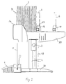
- FIG. 1 and 2 each show a side view of the complete machine with a stack of objects 2 with a small format or of objects 5 with a larger format, the be transferred to a further processing unit after the separation.
- the feeder the objects 2.5 are carried out with a horizontally displaceable trolley 10 with a holding bracket 6.
- the bracket 6 and another bracket 29 at the opposite end of the Stacks prevent the stack from tipping over.
- the ones to be separated Objects for example, envelopes 2, 5 fed from a stack.
- FIG. 1 and Fig. 2 an envelope 2 and 5 has been separated and issued. He's lying on one Scales of a franking device 1, which due to the weight of the franking on the envelope 2, 5 attaches and then for example forwards it to a shipping unit.
- the machine is carried by a bracket 30 with a vertical support 49. Your height above the Footprint is provided on both sides by hand screws 3 on guides 4 of the carrier 49 adjustable.
- Hoods 14 attached on both sides cover parts of the machine drive and protect it
- FIG. 3 shows a side view into the machine and FIG. 4 shows a top view of the machine.
- Fig. 3 is the hood 14 facing the viewer (Fig.1 and 2) and the side wall 7B of a frame 7 omitted.
- Cross profiles 8A ... 8F connect the side walls 7A and 7B and form with them the frame 7.
- the frame 7 has parallel to the side walls 7A, 7B extending longitudinal profiles 50, 51, which act as a support for the stack and as slide rails serve for the trolley 10.
- In the longitudinal direction there is at least one guide shaft 9 in the frame 7 used.
- the trolley 10 is guided by two guide bearings 11 from the guide shaft 9.
- a Drive shaft 12 drives two belts 13 rotating on rollers 42A, 42B.
- the rollers 42A are arranged on the drive shaft 12 and the rollers 42B on a shaft 66.
- the straps 13 are connected to the trolley 10 with fastening means 52.
- the trolley 10 has a stop 32 and a spring system 23 with a spring 33 and a U-shaped spring holder 34.
- the stop 32 is via the spring system 23 after all Pages freely connected to the trolley 10 and is pressed together when Spring 33 pushed against the trolley 10.
- the spring-loaded stop 32 in conjunction with a pre-separation stage 36 one gentle pressure in the transfer space 31.
- the drive of the machine is for the sake of Clarity only hinted at. It is on the left and right outside on the side walls 7A, 7B distributed under the hoods 14. Details of the drive are described below with reference to FIG. 7 described.
- Fig. 5a shows details of the separation in a sectional view and Fig. 5b in a plan view.
- the singulation has two singularly structured singulation stages arranged one above the other 37 and 38. These essentially consist of a singling element V1 or V2 and a separating roller 18 or 18A arranged opposite one another at the same height.
- the separation rolls 18 and 18A are arranged on separating shafts 17 and 17A, respectively.
- the separating element V consists essentially of 3 Parts, namely a sleeve 53 with rubber coating 60, an adjusting sleeve 54 and a wrap spring 55, which are arranged on a shaft 25.
- Sleeve 53 and adjusting sleeve 54 are preferred made of plastic. Their bore also serves as a bearing on the shaft 25.
- Both sleeves 53, 54 are secured with a fine toothing 56 against rotation.
- the pods 53, 54 can be extended axially. As a result, the toothing 56 can be adjusted, until the wrap spring 55, which is somewhat oversize and one in diameter compared to the shaft 25 increasing winding reserve, has reached the desired torque.
- Both Ends of the wrap spring 55 are fixed to the sleeves.
- the sleeves 53, 54 then become axial pressed together and snap.
- the torque of the separating element V can can be adjusted in this way as required.
- the separating element V can in a direction of rotation to a certain desired Torque, i.e. be set to a freewheel with a certain rotational resistance.
- a certain desired Torque i.e. be set to a freewheel with a certain rotational resistance.
- the sleeve 53 in one direction with a freewheel determined by the torque turn on shaft 25.
- the sleeve 53 is based on the principle a wrap spring clutch is blocked and cannot rotate.
- the shaft 25 of the upper separating element V1 (Fig.5) is driven by a cardan shaft 41. It is in one Frame 7 fastened holder 26 and can easily move in the radial direction (e.g. by about 7 mm) move.
- a spring 27 enables this movement and the necessary compressive force can can be adjusted by a knurled nut 28 acting on the spring 27.
- the pressure between the separating roller 18 and the separating element V1 and. the Torque of the separating element V1 must have a certain relationship to one another exhibit. If there are no sheets in between, the separating roller 18 must Single element V1 can still drive, i.e. the separating element V1 must turn.
- the correct functioning of the separation is guaranteed if by appropriate Adjusting the knurled nut 28 the friction between two successive Envelopes (B1 and B2 in Fig. 5a) is smaller than the torque of the separating element V1, i.e. in this case the envelope B1 must grind on the envelope B2 and the envelope B2 remains or will remain together with the separating element V1 pushed back and then stands still until the envelope B1 completely completes the level 37 happened.
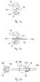
- FIG. 9a shows the Mode of operation if a single envelope B1 in a separation level, e.g. in the 5 reaches the upper singulation stage 37.
- the separating shaft is rotating 17 and shaft 25 clockwise.
- the separating element V1 rotates counterclockwise with an adjustable freewheel.
- the roller 18 forces the opposite one Separation element V1 to rotate counterclockwise.
- Fig. 9b illustrates the behavior of a singulation stage when several objects arrive in this area at the same time.
- the set torque is Separating element V1 greater than the friction between the envelopes B1 and B2. Therefore, the separating element V1 pushes the ones lying under the uppermost envelope B1 Envelopes back. The top envelope B1 is pushed forward unhindered and grinds over the envelope B2 below. If the last envelope arrives, the case according to FIG. 9a occurs again.
- FIG. 5 An execution of the machine with only one separation stage is conceivable.
- the one shown in Fig. 5 Version with two overlapping and identically structured separation stages 37, 38 increases the safety and reliability of the separation process. In particular, such a structure ensures a straight feed of those to be processed Objects without special guide elements. Both isolation levels 37, 38 remain completely autonomous in their function.
- the second (lower) separating stage 38 from a separating roller 18A with a shaft 17A and one Singling element V2, which is constructed identically to the singling element V1 Separation stage 37.
- the separation rollers 18 and 18A are in the direction of travel of the objects (in Fig.
- the freewheeling direction corresponds to the direction of rotation of the separating shafts 17 and 17A of the separating rollers 18 and 18A, respectively. In the other direction they are Separating rollers 18, 18A are fixedly coupled to the separating shaft 17 or 17A.
- a pre-separation stage 36 is also provided in the machine. Details the pre-separation stage 36 are shown in FIG. 10. It consists of a pre-separation wave 17B, from a pre-singling roller that is free-running on the shaft 17B in both directions of rotation 18B and a freewheel sleeve 39.
- the shaft 17B is on both sides on arms 20, 20A (Fig. 7) rotatably mounted.
- the arms 20, 20A are articulated, for example on the separating shaft 17.
- the pre-separation shaft 17B thus forms a rocker with the arms 20, 20A 64.
- the freewheel sleeve 39 is next to the pre-separation roller 18B on the pre-separation shaft 17B arranged. It is only in the running direction of the objects to be separated, in Fig. 3 down free running on the pre-separation shaft 17B, i.e. rotatable.
- the pre-separation roller 18B and the freewheel sleeve 39 each have a driver pin 40A or 40 (FIG. 10), which axially in the same Distance from the shaft 17B and are directed towards each other.
- the pre-separation role Like the separating rollers 18, 18B, 18B is preferably provided with a rubber covering Mistake.
- the pre-separation stage 36 essentially has the following two functions: First, it controls the switching on and off of the feed of the trolley 10 via the rocker 64. Second, it ensures that the first (foremost) envelope from the stack in the transfer space 31 with a certain pressure in the upper separating stage 37 with the separating roller 18 and the separating element V1 arrives (Fig. 3). Because the singling element V1 and the singling roll 18 have a greater common peripheral speed than the pre-singling roll 18B, the pre-singling roll 18B rotates - driven by the envelope - faster than the pre-singling shaft 17B.
- the driver pin 40A (FIG.
- protruding from the pre-singling roller 18B therefore moves away from the driving pin 40 in the freewheel sleeve 39 in order to hit the driving pin 40 again after a partial rotation of the pre-singling roller 18B and thereby take the freewheel sleeve 39 with it.
- the pre-separation roller 18B remains until the drive of the pre-separation shaft 17B via the freewheel sleeve 39 and the pin 40 catches up with the pre-separation roller 18B with the pin 40A and can advance the next envelope.
- This arrangement prevents the subsequent second envelope from being inserted at the wrong time. In addition, excessive wear of the pre-separation roller 18B is prevented.
- FIG. 7 details of the drive of the machine are in two side views and in one Shown top view.
- the top view is two-dimensional for better understanding, i.e. in one level.
- a laterally mounted motor 15 drives a motor shaft 16. about a reduction gear with gears 100 ... 106 distributed on both sides of the machine and 107 ... 111, the singulation waves 17, 17A, the pre-singulation wave 17B and the feed of the trolley 10 is driven.
- the separating shaft 17A and the cardan shafts 41 (Fig. 5b) driven by the separating shaft 17 in a 1: 1 ratio.
- the shaft 17B runs at a ratio of 1: 3.5 slower than the shaft 17.
- the drive for the trolley 10 has its origin in the singling wave 17 and runs along the dashed line Line in the direction of arrow D to shaft 12.
- the drive for the separating shafts 17, 17A, 17B has its origin in the motor shaft 16 and runs along the dashed line in the direction of the arrow C.
- the branching of the drive takes place with the gears 102, 103, which are fixed are interconnected.
- the switch 22 is arranged with respect to the rocker 64 so that the pressure of the stack on the pre-separation roller 18B and thus on the rocker 64 cannot exceed a certain value. So that is ensures that the front envelope of the stack is never between the stack and the Pre-separation roller 18B is pinched, thereby blocking the separation process can.
- the switch 22 switches the electric clutch 19 off and the movement of the trolley 10 is stopped. At this moment, the trolley 10 free running in both directions (forward and backward direction) with a certain running resistance and the previously compressed spring 33 of the stop 32 relaxes again.
- the stop 32 then only has a supporting function for the stack. As soon as the pressure of the Stack on the pre-separation roller 18B in the course of the separation process a certain one Value falls below, the feed of the trolley 10 by the switch 22 on the electric clutch 19 switched on again.
- the trolley 10 can be moved manually in both directions be pushed. This simplifies the loading of the stack, in particular also for reloading during the operation of the machine.
- the trolley 10 is initially until Stack pushed and ensures at all times to keep the stack upright. After deducting the of the last pulp envelope from the stack, the stop 32 touches the pre-singling roller 18B. Finally, the rocker 64 stops the feed of the trolley 10 via the switch 22.
- FIG. Another possible application of the machine according to the invention is shown in FIG.
- the stacked envelopes are moved vertically from bottom to top of trolley 10 Transfer room led.
- the feed, the pre-separation stage 36 and the separation stages 37, 38 are rotated upwards by 90 degrees compared to the previously described example.
- the envelopes are separated from the top of the stack and the envelopes are issued individually in a horizontal direction.
- the stop 32 and the spring system 23 with the spring 33 and the spring holder 34 can be omitted here.
- an electrical circuit board 35 which contains a counter.
- a photocell the sequence of the machine controls when the envelopes exit the machine.
- the machine can be started / stopped, for example, from a franking machine via a photocell to be controlled.
- the machine described is not only suitable for separating envelopes, but also generally for separating sheet-shaped objects of various thicknesses and in various formats.
- Objects such as paper sheets from 70 to 160 grams / m2, empty or filled envelopes in open or closed condition, Labels on carrier paper, compact disks etc. up to a thickness of approx. 6 mm without any problems to process.
- the batch to be processed can be of any length. If the stack is short, the machine can also work without mechanical stack feed. In this case, the machine must be inclined by approx. 45 ° in the direction of the separation stage, e.g. in a processing line including from a printer and an inserter, the Machine is inserted as a buffer between the printer and the inserter.
- the Stack advanced by its own weight on the longitudinal profiles 50, 51.
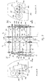
- FIG. 11 and 12 show a further embodiment of the machine, FIG. 11 being a sectional view the top view of Fig. 12.
- This embodiment is particularly suitable for Reliable separation of relatively thin and flexible objects, such as paper sheets 5 (stationery). It differs essentially from the machine described above through a built-in chain guide unit 44 and through a single separation stage 43.
- the chain guide unit 44 has at least two parallel to the guide shaft 9 Circulating chains 57, 58.
- a roller chain such as that is suitable as circulating chains 57, 58 is used for example in bicycles. There is a circulating chain on each side of the guide shaft 9 57 and 58 respectively.
- the circulating chains 57, 58 are passed through their chain links Rails 71A, 71B - for example parallel to the guide shaft 9 vertically arranged sheets - are carried and are on the rails 71, 71A in both directions parallel to the guide shaft 9 free running.
- the rails 71, 71A are fastened to the frame 7 on cross members 75A, 75B. she simultaneously serve as a guideway for the trolley 46.
- the rails 71A, 71 B on each side has a horizontally attached support 74A, 74B on which the trolley 46 can slide.
- the circulation chains 57, 58 replace the longitudinal profiles 50, 51 in the previously described Embodiment as a carrier for the sheets 5.
- the trolley 46 the drive of which is basically the same as in the embodiment according to 1ff, has a holding bracket 59 which is articulated via a tension spring 47.
- the Retaining bracket 59 can therefore move backwards - to the right in FIG. 11. This allows one unhindered reloading of the stack of sheets 5 even while the machine is operating.
- the trolley 46 backs away in the direction of the arrow (FIG. 11), a certain one Resistance of the trolley 46 in this direction a falling or slipping of the stack prevented.
- a chain tensioner 45 prevents the circulating chains 57, 58 from loosening.
- the stack with the sheets 5 to be separated is located directly on the circulating chains 57, 58 between the bracket 59 and a further holder 61 in the area of separation. The stack is moved by the trolley 46 in the direction of the separation.
- the simplified separation essentially consists of a pre-separation level 77 and a singling level 43, which is identical in structure and function to the pre-singling level 36 and the singulation stage 37 in FIG. 3. Their arrangement is also shown in FIG the machine as described with reference to Fig. 3ff.
- On a rocker 76 are a pre-separation role 62 and next to it a freewheel sleeve with opposing driving pins arranged according to Fig. 10.
- the pre-separation roller 62 and the separation roller 63 are arranged on transverse shafts 72, 73 which are rotatably attached to the rocker 76 are.
- the rocker 76 is articulated at the pivot point 65 via the shaft 73 on the frame 7 and connected to a spring 21 attached to the frame 7.
- On frame 7 is also the separating element V1 attached, the pressure against the separating roller 63 with a knurled nut 69 and a spring 68 can be adjusted.
- On the frame 7 there is still at least one sliding plate 70 attached approximately over the entire width of the machine.
- the drive for the feed of the trolley 46 and the various elements of the Separations are identical to the drive in the previously described version of the machine.
- the foremost sheets 5 come in when the stack is advanced the transfer space 31 and stand vertically on the sliding plate 70.
- the foremost sheet is from the pre-separation roller 62 down between the separation roller 63 and the separation element V1 pushed, taken over by them and then ejected in the direction of the arrow.
- the separation of the sheets 5 entering the transfer space 31 is basically the same as in the embodiment described with reference to FIG. 3ff.
- the design of the machine according to FIGS. 11 and 12 uses the same basic structure the frame 7, the carrier 49, the feed for the trolley 10 and the gear with the Motor 15 as the machine according to Fig. 1ff.
- the chain guide unit 44 can be used as Module are installed, the rails 71A, 71B are attached to the frame 7 and the Replace longitudinal profiles 50, 51 (Fig. 4).
- the simplified separation can also be done with the Pre-singling role 62 and the singling level 43 instead of the singling Install as shown in Fig. 3.
- the drive of the machine can be used for this embodiment 3ff are adopted unchanged. So the machine can be started easily adapt to changing requirements regarding the items to be separated.
- the individual was output Objects down (Fig. 1 and 2) with horizontal feeding of the objects and laterally (Fig. 8) with feeding the objects from below.
- Fig. 8 By making simple adjustments it is also possible in both embodiments for further output directions for the individual To provide objects.
- the basic structure of those standing on the console 30 remains Machine with the carrier 49 and the frame 7 unchanged.
- the pre-separation system and the separation system rotated by 90 degrees be arranged in the frame 7. In this case there is in particular the pre-separation wave and the separating shafts perpendicular to the base of the machine.
Landscapes
- Engineering & Computer Science (AREA)
- Mechanical Engineering (AREA)
- Sheets, Magazines, And Separation Thereof (AREA)
- Sorting Of Articles (AREA)
- Pile Receivers (AREA)
- Processing And Handling Of Plastics And Other Materials For Molding In General (AREA)
- Combined Means For Separation Of Solids (AREA)
Abstract
Description
- Fig. 1,2
- je eine Seitenansicht der vollständigen Maschine für zwei verschiedene Anwendungen (unterschiedliche Formate der verarbeiteten Gegenstände)
- Fig. 3
- eine Seitenansicht der Maschine ohne Seitenwand
- Fig. 4
- eine Sicht von oben auf die Maschine
- Fig. 5
- die Vereinzelungsstufen in einem Schnittbild und einer Sicht von vorne
- Fig. 6
- Einzelheiten eines Vereinzelungselementes
- Fig. 7
- verschiedene Darstellungen des Antriebes der Maschine
- Fig. 8
- eine weitere Anwendungsmöglichkeit der Maschine
- Fig. 9
- die Funktionsweise der Vereinzelung (Separierung)
- Fig. 10
- Einzelheiten der Vorvereinzelungsstufe
- Fig. 11
- eine weitere Ausführungsform der Maschine in einem Schnittbild
- Fig. 12
- die weitere Ausführungsform der Maschine gemäss Fig. 11 in einer Draufsicht
Erstens steuert sie das Ein- und Ausschalten des Vorschubes der Laufkatze 10 über die Wippe 64. Zweitens gewährleistet sie, dass der erste (vorderste) Briefumschlag vom Stapel im Übergaberaum 31 mit einem bestimmten Druck in die obere Vereinzelungsstufe 37 mit der Vereinzelungsrolle 18 und dem Vereinzelungselement V1 gelangt (Fig. 3). Weil das Vereinzelungselement V1 und die Vereinzelungsrolle 18 eine grössere gemeinsame Umfangsgeschwindigkeit aufweisen als die Vorvereinzelungsrolle 18B, dreht die Vorvereinzelungsrolle 18B - getrieben durch den Briefumschlag - schneller als die Vorvereinzelungswelle 17B. Der aus der Vorvereinzelungsrolle 18B herausragende Mitnehmerstift 40A (Fig. 10) entfernt sich deshalb vom Mitnehmerstift 40 in der Freilaufhülse 39, um nach einer Teilumdrehung der Vorvereinzelungsrolle 18B wieder auf den Mitnehmerstift 40 zu stossen und dabei die Freilaufhülse 39 mitzunehmen. Bei Erreichen des Endes des ersten Briefumschlages bleibt die Vorvereinzelungsrolle 18B solange stehen, bis der Antrieb der Vorvereinzelungswelle 17B über die Freilaufhülse 39 und den Stift 40 die Vorvereinzelungsrolle 18B mit dem Stift 40A wieder einholt und den nächsten Briefumschlag vorschieben kann. Mit dieser Anordnung wird verhindert, dass der nachfolgende zweite Briefumschlag im falschen Zeitpunkt eingeschoben wird. Zudem wird eine übermässige Abnützung der Vorvereinzelungsrolle 18B verhindert.
- 1
- Frankiereinrichtung
- 2
- Gegenstand mit kleinem Format/Briefumschlag
- 3
- Handschraube
- 4
- Führung
- 5
- Gegenstand mit grossem Format/Briefumschlag
- 6
- Haltebügel
- 7
- Rahmen
- 7A, 7B
- Seitenwände des Rahmens 7
- 8A...8F
- Querprofile
- 9
- Führungswelle
- 10
- Laufkatze
- 11
- Gleitlager
- 12
- Antriebswelle
- 13
- Riemen
- 14A, 14B
- Hauben
- 15
- Motor
- 16
- Motorwelle
- 17
- Vereinzelungswelle
- 17A
- Vereinzelungswelle
- 17B
- Vorvereinzelungswelle
- 18
- Vereinzelungsrolle der oberen Vereinzelungsstufe
- 18A
- Vereinzelungsrolle der unteren Vereinzelungsstufe
- 18B
- Vorvereinzelungsrolle
- 19
- Elektrokupplung
- 20, 20A
- Arme
- 21
- Feder
- 22
- Schalter
- 23
- Federsystem mit Feder 33 und Federhalter 34
- 24, 24A
- Reduktionsgetriebe
- 25
- Welle von Vereinzelungselement V1
- 25A
- Welle von Vereinzelungselement V2
- 26
- Halter
- 27
- Feder für Vereinzelungselement
- 28
- Rändelmutter für Vereinzelungselement
- 29
- Haltebügel
- 30
- Konsole
- 31
- Übergaberaum
- 32
- Anschlag Laufkatze
- 33
- Feder
- 34
- Federhalter
- 35
- elektrische Leiterplatte
- 36
- Vorvereinzelungsstufe
- 37
- obere Vereinzelungsstufe
- 38
- untere Vereinzelungsstufe
- 39
- Freilaufhülse
- 40
- Mitnehmerstift Freilauf
- 40A
- Mitnehmerstift Vorvereinzelungsrolle
- 41, 41A
- Kardanwelle
- 42A, 42B
- Rollen
- 43
- Vereinzelungsstufe (Fig. 11)
- 44
- Kettenführungseinheit
- 45
- Kettenspanner
- 46
- Laufkatze
- 47
- Spannfeder
- 48
- Nachladepaket
- 49
- Träger
- 50
- Längsprofil (Gleitschiene)
- 51
- Längsprofil (Gleitschiene)
- 52
- Befestigungsmittel Laufkatze an Riemen
- 53
- Hülse
- 54
- Einstellhülse
- 55
- Schlingfeder
- 56
- Verzahnung
- 57
- Umlaufkette
- 58
- Umlaufkette
- 59
- Haltebügel der Laufkatze 46
- 60
- Gummiüberzug
- 61
- Halter
- 62
- Vorvereinzelungsrolle (Fig.11)
- 63
- Vereinzelungsrolle (Fig.11)
- 64
- Wippe (Fig. 3)
- 65
- Drehpunkt von Träger 64
- 66
- Welle für Rollen 42B
- 67
- Vereinzelungselement
- 68
- Feder
- 69
- Rändelmutter
- 70
- Gleitblech
- 71A, 71B
- Schiene für Kettenführung
- 72
- Vorvereinzelungswelle
- 73
- Vereinzelungswelle
- 74A, 74B
- Träger für Laufkatze
- 75A, 75B
- Querträger
- 76
- Wippe (Fig. 11)
- 77
- Vorvereinzelungsstufe (Fig. 11)
- 100 ... 111
- Zahnräder (Getriebe)
- V1
- erstes (oberes) Vereinzelungselement
- V2
- zweites (unteres) Vereinzelungselement
Claims (18)
- Maschine zum Vereinzeln von in einem Stapel enthaltenen flachen Gegenständen (2;5), gekennzeichnet durch folgende Merkmale:eine Vorschubeinheit (9,12,13,19) mit einer Laufkatze (10) zum Zuführen der Gegenstände (2;5),eine Vorvereinzelungsstufe (36;77) zur Aufnahme der zugeführten Gegenstände (2;5) und zur stückweisen Weitergabe der Gegenstände (2;5)mindestens eine Vereinzelungsstufe (37;43) zur Aufnahme der von der Vorvereinzelungsstufe (36;77) erhaltenen Gegenstände (2;5) und zur stückweisen Ausgabe der Gegenstände (2;5)eine Antriebseinheit (15,16,17) für die Vorschubeinheit (9,12,13,19), für die Vorvereinzelungsstufe (36;77) und für die Vereinzelungsstufen (37,38;43), wobei die Antriebseinheit (15,16,17) den Vorschub der Laufkatze (10) unterbricht, wenn im Übergaberaum (31) zwischen der Laufkatze (10) und der Vorvereinzelungsstufe (36;77) die Menge von Gegenständen (2;5) einen bestimmten Wert überschreitet.
- Maschine nach Anspruch 1, dadurch gekennzeichnet, dass zwei Vereinzelungsstufen (37,38) vorgesehen sind.
- Maschine nach Anspruch 1 oder 2, dadurch gekennzeichnet, dass die Vereinzelungsstufen (37,38;43) eine auf einer Vereinzelungswelle (17,17A;73) angeordnete Vereinzelungsrolle (18,18A;63) und ein gegenüberliegendes Vereinzelungselement (V1,V2) aufweisen, und dass die Vereinzelungsrollen (18,18A;63) in Laufrichtung der Gegenstände (2;5) einen Freilauf aufweisen.
- Maschine nach Anspruch 3, dadurch gekennzeichnet, dass der Druck eines Vereinzelungselementes (V1,V2) auf die gegenüberliegende Vereinzelungsrolle (18,18A;63) einstellbar ist.
- Maschine nach Anspruch 3 oder 4, dadurch gekennzeichnet, dass das Vereinzelungselement (V1,V2) aus einer Hülse (53) und einer Einstellhülse (54) mit ineinander greifenden Verzahnungen (56) sowie aus einer Schlingfeder (55) und einer Welle (25) besteht.
- Maschine nach Anspruch 1, dadurch gekennzeichnet, dass die Vorvereinzelungsstufe (36;77) eine in beiden Drehrichtungen freilaufende Vorvereinzelungsrolle (18B;62) mit einem achsial herausragenden Mitnehmerstift (40A) aufweist, die auf einer Welle (17B;72) angeordnet ist, und dass auf der Welle (17B;72) neben der Vorvereinzelungsrolle (18B;62) eine in Laufrichtung der Gegenstände (2;5) freilaufende Freilaufhülse (39) mit einem achsial herausragenden Mitnehmerstift (40) angeordnet ist, der gegen den Mitnehmerstift (40A) gerichtet ist und in gleichem Abstand wie der Mitnehmerstift (40A) von der Welle (17B;72) angebracht ist.
- Maschine nach Anspruch 6, dadurch gekennzeichnet, dass die Vorvereinzelungsrolle (188;62) drehbar an gelenkig am Rahmen (7) befestigten Armen (20,20A) angebracht ist und mit diesen eine Wippe (64;76) bildet, die bei Erreichen eines bestimmten Druckes der zugeführten Gegenstände (2;5) auf die Vorvereinzelungsrolle (18B;62) den Vorschub der Laufkatze (10;46) über einen Schalter (22) unterbricht.
- Maschine nach einem der vorangehenden Ansprüche, dadurch gekennzeichnet, dass eine modular einbaubare Kettenführungseinheit (44) mit Umlaufketten (57,58) vorgesehen ist, auf denen die Gegenstände (2;5) aufliegen und zur Vorvereinzelungsstufe (36;77) transportiert werden.
- Maschine nach Anspruch 8, dadurch gekennzeichnet, dass die Umlaufketten (57,58) freilaufend auf Schienen (71A,71B) angeordnet sind und dass die Schienen (71A,71B) mit Trägern (74A,74B) für die Laufkatze (46) versehen sind.
- Maschine nach Anspruch 8 oder 9, dadurch gekennzeichnet, dass am Rahmen (7) ein gegen die Vereinzelungsstufe (43) gerichtetes Gleitblech (70) angebracht ist.
- Maschine nach einem der vorangehenden Ansprüche, dadurch gekennzeichnet, dass die Vorvereinzelungsstufe (36;77) und die Vereinzelungsstufen (37,38;43) horizontal zur Standfläche der Maschine angeordnet sind.
- Maschine nach einem der Ansprüche 1 bis 10, dadurch gekennzeichnet, dass die Vorvereinzelungsstufe (36;77) und die Vereinzelungsstufen (37,38;43) vertikal zur Standfläche der Maschine angeordnet sind.
- Maschine nach Anspruch 11, dadurch gekennzeichnet, dass die Vorvereinzelungsstufe (36;77) entweder oberhalb oder unterhalb der Vereinzelungsstufen (37,38;43) angeordnet ist.
- Maschine nach einem der vorangehenden Ansprüche, dadurch gekennzeichnet, dass die Laufkatze (10;46) ein Federsystem (23) mit einem Anschlag (32) aufweist, der über einen Federhalter (34) und eine Feder (33) in allen Richtungen beweglich mit der Laufkatze (10) verbunden ist.
- Maschine nach Anspruch 14, dadurch gekennzeichnet, dass die Laufkatze (46) einen Haltebügel (59) aufweist, der gelenkig gelagert und entgegen der Vorschubrichtung der Laufkatze (46) auslenkbar ist.
- Maschine nach Anspruch 14 oder 15, dadurch gekennzeichnet, dass die Laufkatze (10;46) bei stillstehendem Vorschub mit einem bestimmten Widerstand in beiden Richtungen bewegbar ist.
- Maschine nach einem der vorangehenden Ansprüche, dadurch gekennzeichnet, dass der Vorschub für die Laufkatze (10;46), der Antrieb für die Vorvereinzelungsstufe (36;77) und der Antrieb für die Vereinzelungsstufen (37,38;43) durch einen Motor (15) über ein Getriebe mit Zahnrädern (100 ... 111) erfolgt.
- Maschine nach einem der vorangehenden Ansprüche, dadurch gekennzeichnet, dass eine Konsole (30) mit Führungen (4) vorgesehen ist, mit der die Höhe der Ausgabe der Gegenstände (2;5) über der Standfläche einstellbar ist.
Applications Claiming Priority (2)
| Application Number | Priority Date | Filing Date | Title |
|---|---|---|---|
| CH20000334 | 2000-02-22 | ||
| CH3342000 | 2000-02-22 |
Publications (3)
| Publication Number | Publication Date |
|---|---|
| EP1127817A2 true EP1127817A2 (de) | 2001-08-29 |
| EP1127817A3 EP1127817A3 (de) | 2001-10-04 |
| EP1127817B1 EP1127817B1 (de) | 2006-10-11 |
Family
ID=4503086
Family Applications (1)
| Application Number | Title | Priority Date | Filing Date |
|---|---|---|---|
| EP01810175A Expired - Lifetime EP1127817B1 (de) | 2000-02-22 | 2001-02-20 | Maschine zum Vereinzeln von flachen Gegenständen |
Country Status (3)
| Country | Link |
|---|---|
| EP (1) | EP1127817B1 (de) |
| AT (1) | ATE342216T1 (de) |
| DE (1) | DE50111171D1 (de) |
Cited By (1)
| Publication number | Priority date | Publication date | Assignee | Title |
|---|---|---|---|---|
| EP1367015A3 (de) * | 2002-05-28 | 2005-05-11 | Kabushiki Kaisha Toshiba | Zuführvorrichtung |
Family Cites Families (11)
| Publication number | Priority date | Publication date | Assignee | Title |
|---|---|---|---|---|
| US4030722A (en) * | 1975-05-13 | 1977-06-21 | Pitney-Bowes, Inc. | Sheet-material separator and feeder system |
| DE2851545C2 (de) * | 1978-11-29 | 1986-03-20 | Licentia Patent-Verwaltungs-Gmbh, 6000 Frankfurt | Vorrichtung zur vereinzelten Abgabe von Briefen u.ä. flachen Sendungen aus einem Stapel |
| DE3706810C1 (de) * | 1987-03-03 | 1988-03-31 | Nixdorf Computer Ag | Regelung einer Abzugseinrichtung fuer Blattmaterial |
| JPH0816938B2 (ja) * | 1989-12-01 | 1996-02-21 | ローレルバンクマシン株式会社 | 紙幣収納箱 |
| JPH03211127A (ja) * | 1990-01-11 | 1991-09-13 | Sharp Corp | 給紙装置 |
| US5083765A (en) * | 1990-07-20 | 1992-01-28 | Actmedia, Inc. | Coupon dispenser |
| JPH0494334A (ja) * | 1990-08-10 | 1992-03-26 | Brother Ind Ltd | 自動給紙装置 |
| CA2045049C (en) * | 1991-06-20 | 1996-04-16 | Jean-Guy Cloutier | Shingled stack height sensing system for book sections conveyor |
| EP0540867B1 (de) * | 1991-09-19 | 1997-01-02 | Oki Electric Industry Co., Ltd. | Tresor und den Tresor enthaltende Anordnung |
| JP3315739B2 (ja) * | 1992-12-10 | 2002-08-19 | 株式会社リコー | 分離コロのトルク発生機構 |
| JPH0971334A (ja) * | 1995-09-04 | 1997-03-18 | Fuji Xerox Co Ltd | 画情報処理装置 |
-
2001
- 2001-02-20 EP EP01810175A patent/EP1127817B1/de not_active Expired - Lifetime
- 2001-02-20 AT AT01810175T patent/ATE342216T1/de not_active IP Right Cessation
- 2001-02-20 DE DE50111171T patent/DE50111171D1/de not_active Expired - Fee Related
Cited By (2)
| Publication number | Priority date | Publication date | Assignee | Title |
|---|---|---|---|---|
| EP1367015A3 (de) * | 2002-05-28 | 2005-05-11 | Kabushiki Kaisha Toshiba | Zuführvorrichtung |
| US7396010B2 (en) | 2002-05-28 | 2008-07-08 | Kabushiki Kaisha Toshiba | Take-out apparatus |
Also Published As
| Publication number | Publication date |
|---|---|
| ATE342216T1 (de) | 2006-11-15 |
| EP1127817A3 (de) | 2001-10-04 |
| DE50111171D1 (de) | 2006-11-23 |
| EP1127817B1 (de) | 2006-10-11 |
Similar Documents
| Publication | Publication Date | Title |
|---|---|---|
| EP1944254B1 (de) | Vorrichtung zum Transport von Druckprodukten | |
| DE69202534T2 (de) | Rollenakkumulator für Bogen. | |
| DE60311778T2 (de) | Zurückziehbare übergabeeinrichtung für eine dosiervorrichtung | |
| DE2029276C3 (de) | Vorrichtung zum Fördern eines Stapels hochkantstehender flachiger Gegenstande | |
| DE2711173B2 (de) | Einrichtung an einer schreibenden oder druckenden Büromaschine zum Beschicken derselben mit Blättern | |
| DE2060946C3 (de) | Vorrichtung zum Öffnen von gefalteten, gebundenen oder gehefteten, mehrblättrigen Papiererzeugnissen | |
| DE2315813B2 (de) | Vorrichtung zum Stapeln von bogenförmigem Material | |
| DE2640497A1 (de) | Buchbindemaschine | |
| DD140132A5 (de) | Vorrichtung zum beschicken einer packmaschine mit suesswaren | |
| DE2600651A1 (de) | Zuteileinrichtung | |
| DE2423885C2 (de) | Vorrichtung zum Übergeben von Stapeln aus blattförmigen Materialzuschnitten | |
| DE3126808C2 (de) | ||
| DE1436485B2 (de) | Vorrichtung zum Befördern, Stapeln und Zählen von Druckschriften | |
| DE1549171C3 (de) | Transportvorrichtung tür Warenpackungen | |
| DE2403410A1 (de) | Vorrichtung zum bedrucken von bogenund blattmaterial unterschiedlicher groesse | |
| DE2307799A1 (de) | Bogenfoerdergeraet, insbesondere fuer druckmaschinen | |
| EP1127817B1 (de) | Maschine zum Vereinzeln von flachen Gegenständen | |
| DE2109468C2 (de) | Faltmaschine zum Umlegen der Laschen von Faltschachteln | |
| DE3534919C2 (de) | ||
| EP0322398B1 (de) | Faltvorrichtung | |
| DE19541278C2 (de) | Stapelvorrichtung für kartenförmige Güter | |
| DE10127993A1 (de) | Vereinzelungsvorrichtung für flache Gegenstände und Vereinzelungsverfahren | |
| DE2039143C3 (de) | ||
| DE2334551A1 (de) | Blattfoerdervorrichtung | |
| DD139827A1 (de) | Anordnung zum zufuehren der aufzeichnungstraeger von einem magazin |
Legal Events
| Date | Code | Title | Description |
|---|---|---|---|
| PUAI | Public reference made under article 153(3) epc to a published international application that has entered the european phase |
Free format text: ORIGINAL CODE: 0009012 |
|
| PUAL | Search report despatched |
Free format text: ORIGINAL CODE: 0009013 |
|
| AK | Designated contracting states |
Kind code of ref document: A2 Designated state(s): AT BE CH CY DE DK ES FI FR GB GR IE IT LI LU MC NL PT SE TR |
|
| AX | Request for extension of the european patent |
Free format text: AL;LT;LV;MK;RO;SI |
|
| RIC1 | Information provided on ipc code assigned before grant |
Free format text: 7B 65H 3/06 A, 7B 65H 3/52 B, 7B 65H 1/02 B, 7B 65H 1/14 B |
|
| AK | Designated contracting states |
Kind code of ref document: A3 Designated state(s): AT BE CH CY DE DK ES FI FR GB GR IE IT LI LU MC NL PT SE TR |
|
| AX | Request for extension of the european patent |
Free format text: AL;LT;LV;MK;RO;SI |
|
| 17P | Request for examination filed |
Effective date: 20020304 |
|
| AKX | Designation fees paid |
Free format text: AT BE CH CY DE DK ES FI FR GB GR IE IT LI LU MC NL PT SE TR |
|
| 17Q | First examination report despatched |
Effective date: 20020517 |
|
| APBX | Invitation to file observations in appeal sent |
Free format text: ORIGINAL CODE: EPIDOSNOBA2E |
|
| APBZ | Receipt of observations in appeal recorded |
Free format text: ORIGINAL CODE: EPIDOSNOBA4E |
|
| APBT | Appeal procedure closed |
Free format text: ORIGINAL CODE: EPIDOSNNOA9E |
|
| GRAP | Despatch of communication of intention to grant a patent |
Free format text: ORIGINAL CODE: EPIDOSNIGR1 |
|
| APAA | Appeal reference recorded |
Free format text: ORIGINAL CODE: EPIDOS REFN |
|
| GRAS | Grant fee paid |
Free format text: ORIGINAL CODE: EPIDOSNIGR3 |
|
| APAF | Appeal reference modified |
Free format text: ORIGINAL CODE: EPIDOSCREFNE |
|
| GRAA | (expected) grant |
Free format text: ORIGINAL CODE: 0009210 |
|
| AK | Designated contracting states |
Kind code of ref document: B1 Designated state(s): AT BE CH CY DE DK ES FI FR GB GR IE IT LI LU MC NL PT SE TR |
|
| PG25 | Lapsed in a contracting state [announced via postgrant information from national office to epo] |
Ref country code: IE Free format text: LAPSE BECAUSE OF FAILURE TO SUBMIT A TRANSLATION OF THE DESCRIPTION OR TO PAY THE FEE WITHIN THE PRESCRIBED TIME-LIMIT Effective date: 20061011 Ref country code: NL Free format text: LAPSE BECAUSE OF FAILURE TO SUBMIT A TRANSLATION OF THE DESCRIPTION OR TO PAY THE FEE WITHIN THE PRESCRIBED TIME-LIMIT Effective date: 20061011 Ref country code: FI Free format text: LAPSE BECAUSE OF FAILURE TO SUBMIT A TRANSLATION OF THE DESCRIPTION OR TO PAY THE FEE WITHIN THE PRESCRIBED TIME-LIMIT Effective date: 20061011 |
|
| REG | Reference to a national code |
Ref country code: GB Ref legal event code: FG4D Free format text: NOT ENGLISH |
|
| REG | Reference to a national code |
Ref country code: CH Ref legal event code: EP |
|
| REG | Reference to a national code |
Ref country code: IE Ref legal event code: FG4D Free format text: LANGUAGE OF EP DOCUMENT: GERMAN |
|
| REF | Corresponds to: |
Ref document number: 50111171 Country of ref document: DE Date of ref document: 20061123 Kind code of ref document: P |
|
| REG | Reference to a national code |
Ref country code: CH Ref legal event code: NV Representative=s name: PETER RUTZ |
|
| PG25 | Lapsed in a contracting state [announced via postgrant information from national office to epo] |
Ref country code: SE Free format text: LAPSE BECAUSE OF FAILURE TO SUBMIT A TRANSLATION OF THE DESCRIPTION OR TO PAY THE FEE WITHIN THE PRESCRIBED TIME-LIMIT Effective date: 20070111 Ref country code: DK Free format text: LAPSE BECAUSE OF FAILURE TO SUBMIT A TRANSLATION OF THE DESCRIPTION OR TO PAY THE FEE WITHIN THE PRESCRIBED TIME-LIMIT Effective date: 20070111 |
|
| PG25 | Lapsed in a contracting state [announced via postgrant information from national office to epo] |
Ref country code: ES Free format text: LAPSE BECAUSE OF FAILURE TO SUBMIT A TRANSLATION OF THE DESCRIPTION OR TO PAY THE FEE WITHIN THE PRESCRIBED TIME-LIMIT Effective date: 20070122 |
|
| PG25 | Lapsed in a contracting state [announced via postgrant information from national office to epo] |
Ref country code: MC Free format text: LAPSE BECAUSE OF NON-PAYMENT OF DUE FEES Effective date: 20070228 |
|
| PG25 | Lapsed in a contracting state [announced via postgrant information from national office to epo] |
Ref country code: PT Free format text: LAPSE BECAUSE OF FAILURE TO SUBMIT A TRANSLATION OF THE DESCRIPTION OR TO PAY THE FEE WITHIN THE PRESCRIBED TIME-LIMIT Effective date: 20070319 |
|
| NLV1 | Nl: lapsed or annulled due to failure to fulfill the requirements of art. 29p and 29m of the patents act | ||
| ET | Fr: translation filed | ||
| GBV | Gb: ep patent (uk) treated as always having been void in accordance with gb section 77(7)/1977 [no translation filed] |
Effective date: 20061011 |
|
| REG | Reference to a national code |
Ref country code: IE Ref legal event code: FD4D |
|
| PLBE | No opposition filed within time limit |
Free format text: ORIGINAL CODE: 0009261 |
|
| STAA | Information on the status of an ep patent application or granted ep patent |
Free format text: STATUS: NO OPPOSITION FILED WITHIN TIME LIMIT |
|
| 26N | No opposition filed |
Effective date: 20070712 |
|
| PG25 | Lapsed in a contracting state [announced via postgrant information from national office to epo] |
Ref country code: GB Free format text: LAPSE BECAUSE OF FAILURE TO SUBMIT A TRANSLATION OF THE DESCRIPTION OR TO PAY THE FEE WITHIN THE PRESCRIBED TIME-LIMIT Effective date: 20061011 |
|
| BERE | Be: lapsed |
Owner name: CRATECH GMBH Effective date: 20070228 |
|
| PG25 | Lapsed in a contracting state [announced via postgrant information from national office to epo] |
Ref country code: BE Free format text: LAPSE BECAUSE OF NON-PAYMENT OF DUE FEES Effective date: 20070228 |
|
| PG25 | Lapsed in a contracting state [announced via postgrant information from national office to epo] |
Ref country code: GR Free format text: LAPSE BECAUSE OF FAILURE TO SUBMIT A TRANSLATION OF THE DESCRIPTION OR TO PAY THE FEE WITHIN THE PRESCRIBED TIME-LIMIT Effective date: 20070112 |
|
| PGFP | Annual fee paid to national office [announced via postgrant information from national office to epo] |
Ref country code: CH Payment date: 20080215 Year of fee payment: 8 |
|
| PGFP | Annual fee paid to national office [announced via postgrant information from national office to epo] |
Ref country code: DE Payment date: 20080219 Year of fee payment: 8 Ref country code: IT Payment date: 20080223 Year of fee payment: 8 |
|
| PGFP | Annual fee paid to national office [announced via postgrant information from national office to epo] |
Ref country code: AT Payment date: 20080215 Year of fee payment: 8 |
|
| PGFP | Annual fee paid to national office [announced via postgrant information from national office to epo] |
Ref country code: FR Payment date: 20080214 Year of fee payment: 8 |
|
| PG25 | Lapsed in a contracting state [announced via postgrant information from national office to epo] |
Ref country code: LU Free format text: LAPSE BECAUSE OF NON-PAYMENT OF DUE FEES Effective date: 20070220 Ref country code: CY Free format text: LAPSE BECAUSE OF FAILURE TO SUBMIT A TRANSLATION OF THE DESCRIPTION OR TO PAY THE FEE WITHIN THE PRESCRIBED TIME-LIMIT Effective date: 20061011 |
|
| PG25 | Lapsed in a contracting state [announced via postgrant information from national office to epo] |
Ref country code: TR Free format text: LAPSE BECAUSE OF FAILURE TO SUBMIT A TRANSLATION OF THE DESCRIPTION OR TO PAY THE FEE WITHIN THE PRESCRIBED TIME-LIMIT Effective date: 20061011 |
|
| REG | Reference to a national code |
Ref country code: CH Ref legal event code: PL |
|
| PG25 | Lapsed in a contracting state [announced via postgrant information from national office to epo] |
Ref country code: AT Free format text: LAPSE BECAUSE OF NON-PAYMENT OF DUE FEES Effective date: 20090220 Ref country code: LI Free format text: LAPSE BECAUSE OF NON-PAYMENT OF DUE FEES Effective date: 20090228 Ref country code: CH Free format text: LAPSE BECAUSE OF NON-PAYMENT OF DUE FEES Effective date: 20090228 |
|
| REG | Reference to a national code |
Ref country code: FR Ref legal event code: ST Effective date: 20091030 |
|
| PG25 | Lapsed in a contracting state [announced via postgrant information from national office to epo] |
Ref country code: DE Free format text: LAPSE BECAUSE OF NON-PAYMENT OF DUE FEES Effective date: 20090901 |
|
| PG25 | Lapsed in a contracting state [announced via postgrant information from national office to epo] |
Ref country code: FR Free format text: LAPSE BECAUSE OF NON-PAYMENT OF DUE FEES Effective date: 20090302 |
|
| PG25 | Lapsed in a contracting state [announced via postgrant information from national office to epo] |
Ref country code: IT Free format text: LAPSE BECAUSE OF NON-PAYMENT OF DUE FEES Effective date: 20090220 |