EP1060880B1 - Vorrichtung zum Einziehen einer Materialbahn in eine Rotationsdruckmaschine - Google Patents
Vorrichtung zum Einziehen einer Materialbahn in eine Rotationsdruckmaschine Download PDFInfo
- Publication number
- EP1060880B1 EP1060880B1 EP00110200A EP00110200A EP1060880B1 EP 1060880 B1 EP1060880 B1 EP 1060880B1 EP 00110200 A EP00110200 A EP 00110200A EP 00110200 A EP00110200 A EP 00110200A EP 1060880 B1 EP1060880 B1 EP 1060880B1
- Authority
- EP
- European Patent Office
- Prior art keywords
- triangle
- web
- hypotenuse
- attached
- guiding device
- Prior art date
- Legal status (The legal status is an assumption and is not a legal conclusion. Google has not performed a legal analysis and makes no representation as to the accuracy of the status listed.)
- Expired - Lifetime
Links
- 239000000463 material Substances 0.000 claims description 45
- 239000000835 fiber Substances 0.000 claims description 12
- 230000002787 reinforcement Effects 0.000 claims description 7
- 239000003351 stiffener Substances 0.000 claims 3
- 239000003082 abrasive agent Substances 0.000 claims 1
- 239000000853 adhesive Substances 0.000 description 8
- 230000001070 adhesive effect Effects 0.000 description 8
- 239000004744 fabric Substances 0.000 description 5
- 238000000034 method Methods 0.000 description 3
- 238000009958 sewing Methods 0.000 description 3
- 239000000725 suspension Substances 0.000 description 3
- 239000002390 adhesive tape Substances 0.000 description 2
- 239000011248 coating agent Substances 0.000 description 2
- 238000000576 coating method Methods 0.000 description 2
- 229920000642 polymer Polymers 0.000 description 2
- 239000012783 reinforcing fiber Substances 0.000 description 2
- 244000059549 Borneo rubber Species 0.000 description 1
- 229920000049 Carbon (fiber) Polymers 0.000 description 1
- 229920004943 Delrin® Polymers 0.000 description 1
- 241000270295 Serpentes Species 0.000 description 1
- 238000010521 absorption reaction Methods 0.000 description 1
- 230000004913 activation Effects 0.000 description 1
- 239000004760 aramid Substances 0.000 description 1
- 229920006231 aramid fiber Polymers 0.000 description 1
- 239000004917 carbon fiber Substances 0.000 description 1
- 239000004918 carbon fiber reinforced polymer Substances 0.000 description 1
- 238000006073 displacement reaction Methods 0.000 description 1
- 230000000694 effects Effects 0.000 description 1
- 239000011152 fibreglass Substances 0.000 description 1
- 239000011521 glass Substances 0.000 description 1
- 230000000977 initiatory effect Effects 0.000 description 1
- 239000002184 metal Substances 0.000 description 1
- 229920001778 nylon Polymers 0.000 description 1
- 229920001084 poly(chloroprene) Polymers 0.000 description 1
- 239000004753 textile Substances 0.000 description 1
- 229920001169 thermoplastic Polymers 0.000 description 1
- 239000004416 thermosoftening plastic Substances 0.000 description 1
- 230000037303 wrinkles Effects 0.000 description 1
Images


Classifications
-
- B—PERFORMING OPERATIONS; TRANSPORTING
- B41—PRINTING; LINING MACHINES; TYPEWRITERS; STAMPS
- B41F—PRINTING MACHINES OR PRESSES
- B41F13/00—Common details of rotary presses or machines
- B41F13/02—Conveying or guiding webs through presses or machines
- B41F13/03—Threading webs into printing machines
Definitions
- the present invention relates to a device for pulling a material web into a Rotary printing machine according to the preamble of claim 1.
- Web feed devices usually require the connection of a web of material with a Guide device, hereinafter referred to generally as "snake".
- a Guide device hereinafter referred to generally as "snake”.
- Such Fasteners are generally designed as a triangle.
- the through the Tension of the web across its width caused side loads mainly on the vertex of the triangle on which it is attached to the guide connected is. Due to these side loads there is a risk that the Web of material from the connecting element detaches that wrinkles form or that the web tears.
- connection of the triangle with the guide device is in this respect difficult than the triangle to avoid misalignment and / or Path shifts are aligned with respect to the transport path of the material web got to. It is known to close the triangles at their apex with the guide device connect. As a result, the triangle can be rotated to a certain extent, which means that the Path at the triangle difficult. Since the triangle is not along the transportation path of the Material web is attached, alignment of the triangle with the web is difficult to to reach. On top of that, it's not easy to position the edge of the triangle so that it coincides with the edge of the web.
- GB 2 315 062 A discloses a web feed device with a feed triangle and an attachment portion for attaching the triangle to one Traction device.
- the triangle has a first side, on the leading side Tip of the attachment section is attached. The trailing end of the first page the triangle has no contact with the fastening section.
- To the Fastening section is again a loop in the running position, which can be hooked into a corresponding counterpart of the pulling device, so that the feed triangle with a tensile force acting on its tip is applied.
- the triangle has a hypotenuse which are parallel and orthogonally reinforcing fibers.
- a device for pulling in a Material web known by means of a pull-in tip, which consists of a first and a second element and which on a leading section with a Pull rope is connected. While the second element to avoid elasticity has sudden or jerky loads on the material web to be drawn in, this can Element, for example, from a tear-resistant textile fabric, which is preferably a Gummed exist.
- the pull-in tip is affected by the pulling action of the Force applied to the pulling rope, which only peaks in the leading Attacks section in the area.
- a device for pulling a web of material into a Web-fed rotary printing press, with a first side of a predetermined length, a Underside and a triangle with hypotenuse, on which the leading end of the material web can be fastened and which is essentially one Gain oriented parallel to the hypotenuse and essentially orthogonal has reinforcement aligned with the hypotenuse, and with a guide device, is characterized by the fact that the triangle essentially along the entire predetermined length of the first side of the triangle releasable with the Guide device is connected.
- a number of Fastening points are provided at which the triangle on the Guide device attached along the entire length of one side of the feed triangle becomes.
- the attachment points facilitate their predetermined position firstly, the alignment of the feed triangle and secondly, make it easy Attach and detach the feed triangle.
- the feed triangle is preferably made of a reinforced material similar to one Fiberglass mat.
- the mat consists of a fabric with right angles arranged fabric fibers. Since the material can be rough, it can also be one Have coating that prevents damage to the web on contact becomes.
- Conceivable materials for the mat contain z. B. aramid or carbon fibers.
- the Coating can e.g. B. from a polymer such. B. rubber or neoprene.
- some of the fibers are in a first Grain direction parallel to the hypotenuse of the triangle, and a another part of the fibers, which is primarily the fixation of the first fibers in the Direction parallel to the hypotenuse of the triangle, but otherwise almost none Contribution to the absorption of the railway forces caused by the railway is in Arranged essentially perpendicular to the first fibers.
- the arrangement of the fibers creates a multitude of quadrilaterals that are parallel Fiber strands can be defined.
- the strands serve to reinforce the structure of the Triangle between the attachment points of the triangle on the guide device and the area where the sheet is attached to the triangle. In this way, one better shifting of the load on the guide element and avoidance of one Displacement of the path causing rotation of the feed triangle reached.
- the essay can preferably be designed to be flexible in the direction of transport of the web, so that it during the web feed can be bent around rollers.
- a preferred material for the stiffening insert is, for example, a polymer; the stiffening attachment can however, it can also be made of metal, provided that it does not come into contact with the rollers Leaves traces. It would be conceivable, for. B. a thermoplastic, Delrin® or Nylon®.
- the essay is preferably attached to the feed triangle such that it is an integral part is the same.
- the attachment can have a gap through which the web is threaded can to attach them to the triangle.
- the web can, for example, through the Gap pulled and then to itself with preferably double-sided adhesive tape be attached.
- the attachment can be used to avoid damage to the web Gap preferably have a rounded edge.
- a terminal strip arrangement can also be arranged on the underside of the draw-in triangle be arranged by means of which the web is attached to the triangle.
- the Terminal strip arrangement can include terminal strips with a rounded cross-section, so preventing the web from tearing.
- the triangle on the Guide device over in a row and preferably parallel to Guide device to be attached to the triangular eyelets.
- the eyelets can be in hooks arranged on the guide device which are attached to the eyelets during hold the web feed.
- the hooks can be designed such that they slide off the eyelets from the hooks are not possible during web feed.
- the hooks can also have an opening and closing function through which they hold the eyelets. The Effect is similar to that of a zipper.
- connection of the hooks with the eyelets for fastening the triangle to the Guide device takes place automatically via an external device, for example in that the hooks are widened with the help of part of the device the eyelets are then placed over the hook, and then bent back in such a way that they jam the eyelets.
- the external Activation device can be used, for example, to fasten the triangle in the area of the roller stand and continue to remove the triangle on Folder can be arranged.
- a zipper is also provided his. This offers the advantage that - with a correspondingly small distance between the Teeth of the zipper - serves as an additional reinforcement. Also has a Zipper basically has a certain flexibility and is easy to open and close. It can also be a device for automatic fastening and Removal of the feed triangle can be provided, the zipper z. B. in the area of the roll changer closes automatically and automatically in the area of the folder opens again.
- Attachment device can be provided, for example, a first section Guide the hook and a second guide section to hang the eyelets into the Can include hooks.
- a gap can preferably be formed in the first guide section through which the hooks can run.
- the hanging device can be used to efficiently attach the feed triangle to the Guide device can be used without the eyelets manually in the associated hook must be hooked. Through the hanging device must Initiation of the fastening process only the first eyelet can be hooked in manually.
- This hanging device is used to automatically insert a variety of eyelets into the the corresponding hook and so the triangle along one side on the Fasten the guide device. With the help of the device it is also possible that Removing the triangle. You can also use automatic unwinding devices for pulling in the feed triangle or take-up devices for removal and Interact storage of the feed triangle.
- the hooks by means of a first Guide section of a suspension device and the eyelets by means of a second guide section of the suspension device can be hooked into the hook.
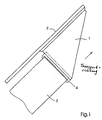
- Fig. 1 shows a first embodiment of a device according to the invention Feeding a material web into a rotary printing press.
- the device comprises a triangle 1, which is attached to a track 3 and a guide device 2.
- the triangle 1 shown in the overall view in FIG. 1 is in the manner of Guide device 2 attached that it in the direction indicated by the arrow can be performed and forms a support for the web 3.
- a stiffening attachment 4 creates additional support across the width of the web 3 and serves as a fastening interface between the web 3 and the triangle 1.
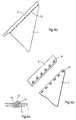
- Fig. 2 shows the orientation of the reinforcement of the feed triangle 1, i. H. the in Essentially parallel to the hypotenuse 7 of the triangle 1 and the essentially orthogonal to the hypotenuse 7 of the triangle 1 reinforcing fibers of the Mat material.
- the triangle 1 is made of a fabric mat.
- the tensile load 8 caused by the web tension has a mat the hypotenuse 7 of the triangle 1 parallel fiber direction 5 and one with respect to Hypotenuse 7 of the triangle 1 orthogonal fiber direction 6.
- the mat is preferably made of a glass fiber-like material, e.g. B. carbon fiber reinforced Plastic, manufactured.
- Fig. 3a reinforcement and fastening arrangements of the triangle 1 are closer shown.
- the feed triangle 1 is with the material web 3 via a stiffening attachment 4th connected.
- the stiffening attachment 4 is by means of an adhesive and / or Sewing connected to the triangle 1, which is indicated by the seam 9.
- the Web 3 is threaded through a gap 10 and preferably by means of double-sided Adhesive tape 11 glued to itself.
- the gap 10 is without a threaded web shown.
- the gap 10 has an edge portion 12 from one rounded material on which a cut of the web due to the thin Material of the stiffening attachment 4 counteracts.
- Fig. 4a is a hook and eye arrangement 13 for attaching the retraction triangle 1 on the guide device 2 shown.
- the triangle 1 is along the length of a Side attached to the guide device 2.
- an eyelet 14 in hooked a hook 15.
- Fig. 4c it can be seen that the hook 15 a in Transport direction of the material web 3 facing bent section 16 includes which the eyelet 14 is held on the hook 15 and a slipping of the Retraction triangle 1 prevented by the guide device 2 when the web at Pulling in under tension.
- the shape of the hook 15 advantageously allows Way also a simple removal of the triangle 1 after the completion of Feeder operation.
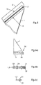
- the zipper 17 shown in this figure has same function as the hook and eye arrangement 13.
- the zipper 17 is with Adhesive 18 and / or by sewing (seam 19) on the guide device 2 and the Triangle 1 attached.
- the position of the adhesive 18 and the seam 19 with respect to the Zipper 17 can of course also reverse to the arrangement shown his. Of course, both attachments can also be made by adhesive or by Sewing is done.
- FIG. 6a shows an attachment of the draw-in triangle 1 to the web 3 according to the invention by means of a terminal strip arrangement 20.
- the Terminal strip arrangement 20 two terminal strips 21, 22, between which the Feed triangle 1 and the material web 3 are clamped.
- the terminal strips 21, 22 are for example by means of preferably countersunk screws 23 arranged in grooves and / or clamps 24 clamped together.
- the Terminal strips 21, 22 preferably have a convex cross section.
- Fig. 7a is a side view of the feed triangle 1 and the guide device 2.
- Zum Fastening the triangle 1 on the guide device 2 is an inventive External hooking device is provided, which attaches the triangle 1 to the Guide device 2 enables each eyelet 14 manually into the individual associated hook 15 must be hooked.
- the attachment device comprises for attaching the triangle 1 to the Guide device 2 a first guide section 25 for the triangle 1 and a second guide section 26 for the guide device 2.
- the first guide portion 25 aligns the eyelets 14 relative to the hooks in the manner 15 from that the end of the hook 15 can be passed through the eyelets 14.
- the guide device 2 during this Process held by the second guide 26 in its predetermined guide path.
- Fig. 7c and 7d is shown how a hook 15 during the threading process by a gap 27 formed in the first guide section 25 runs. After hanging the eyelets 14 into the hook 15, the triangle 1 and the guide device 2 are parallel aligned so that the eyelet 14 is hooked onto the hook 15. In this way, a Slipping of the triangle 1 from the guide device 2 during Rail transport prevented.
Landscapes
- Engineering & Computer Science (AREA)
- Mechanical Engineering (AREA)
- Replacement Of Web Rolls (AREA)
- Rotary Presses (AREA)
Description
- Fig. 1
- eine teilweise, schematische Draufsicht einer erfindungsgemäßen Bahneinzugsvorrichtung mit einem Einzugsdreieck, das an einer Führungseinrichtung und einer Materialbahn befestigt ist;
- Fig. 2
- eine detaillierte Draufsicht eines als eine Gewebematte ausgebildeten Einzugsdreiecks;
- Fig. 3a
- eine teilweise Draufsicht des an der Materialbahn befestigten Einzugsdreiecks;
- Fig. 3b
- eine teilweise, vergrößerte Draufsicht eines Abschnitts des in Fig. 3a gezeigten Einzugsdreiecks ohne Materialbahn;
- Fig. 3c
- einen Querschnitt in der in Fig. 3 gezeigten Pfeilrichtung entlang der Linie III-III;
- Fig. 4a
- eine teilweise Draufsicht eines mittels Haken und Ösen an der Führungseinrichtung befestigen Einzugsdreiecks;
- Fig. 4b
- eine teilweise, vergrößerte Draufsicht eines Abschnitts des in Fig. 4a gezeigten Einzugsdreiecks mit der Führungseinrichtung;
- Fig. 4c
- eine weitere teilweise, vergrößerte, perspektivische Schnittansicht, in der die Haken und Ösen näher gezeigt sind;
- Fig. 5
- eine teilweise Draufsicht des mittels eines Reißverschlusses an der Führungseinrichtung befestigen Einzugsdreiecks;
- Fig. 6a
- eine verkleinerte Draufsicht auf das mit einer Klemmleistenanordnung an der Materialbahn befestigte Einzugsdreieck;
- Fig. 6b
- eine Seitenansicht des in Fig. 6a gezeigten Einzugsdreiecks mit Klemmleistenanordnung und Materialbahn;
- Fig. 6c
- eine Querschnittsansicht der Klemmleisten, des Einzugsdreiecks und der Bahn;
- Fig. 7a
- eine Seitenansicht des Einzugsdreiecks, der Führungseinrichtung und der Einhängevorrichtung;
- Fig. 7b
- eine teilweise, vergrößerte Seitenansicht des Einzugsdreiecks, der Führungseinrichtung und der Einhängevorrichtung;
- Fig. 7c
- eine Schnittansicht des ersten Führungsabschnitts der Einhängevorrichtung; und
- Fig. 7d
- eine Rückansicht des ersten Führungsabschnitts.
- 1
- Einzugsdreieck
- 2
- Führungseinrichtung
- 3
- Materialbahn
- 4
- Versteifungsaufsatz
- 5
- parallele Faserrichtung
- 6
- orthogonale Faserrichtung
- 7
- Hypotenuse des Einzugsdreiecks
- 8
- Belastung
- 9
- Naht
- 10
- Spalt
- 11
- Klebeband
- 12
- Kantenabschnitt
- 13
- Haken- und Ösenanordnung
- 14
- Ösen
- 15
- Haken
- 16
- gebogener Abschnitt
- 17
- Reißverschluss
- 18
- Klebstoff
- 19
- Vernähnaht
- 20
- Klemmleistenanordnung
- 21
- Klemmleiste
- 22
- Klemmleiste
- 23
- Schrauben
- 24
- Klemmen
- 25
- erster Führungsabschnitt
- 26
- zweiter Führungsabschnitt
- 27
- Spalt
Claims (15)
- Vorrichtung zum Einziehen einer Materialbahn (3) in eine Rollenrotationsdruckmaschine,
mit einem eine erste Seite einer vorgegebenen Länge, eine Unterseite und eine Hypotenuse aufweisenden Einzugsdreieck (1), an welchem das vorlaufende Ende der Materialbahn (3) befestigbar ist und welches eine im Wesentlichen parallel zur Hypotenuse (7) ausgerichtete Verstärkung (5) sowie eine im Wesentlichen orthogonal zur Hypotenuse (7) ausgerichtete Verstärkung (6) aufweist, und mit einer Führungseinrichtung (2),
dadurch gekennzeichnet, dass das Einzugsdreieck (1) im Wesentlichen entlang der gesamten vorgegebenen Länge der ersten Seite des Einzugsdreiecks (1) lösbar mit der Führungseinrichtung (2) verbunden ist. - Vorrichtung nach Anspruch 1,
dadurch gekennzeichnet, dass die erste Seite des Einzugsdreiecks (1) an vorgegebenen Befestigungspunkten an der Führungseinrichtung (2) befestigbar ist. - Vorrichtung nach einem der vorhergehenden Ansprüche,
dadurch gekennzeichnet, dass das Einzugsdreieck (1) an der Führungseinrichtung (2) mittels Haken (15) und Ösen (14) befestigbar ist. - Vorrichtung nach einem der Ansprüche 1 oder 2,
dadurch gekennzeichnet, dass das Einzugsdreieck (1) mittels eines Reißverschlusses (17) an der Führungseinrichtung (2) befestigbar ist. , - Vorrichtung nach einem der vorhergehenden Ansprüche,
dadurch gekennzeichnet, dass das Einzugsdreieck (1) aus einem verstärkten Material besteht. - Vorrichtung nach einem der vorhergehenden Ansprüche,
dadurch gekennzeichnet, dass das Einzugsdreieck (1) aus einem Gewebematerial besteht. - Vorrichtung nach Anspruch 6,
dadurch gekennzeichnet, dass das Gewebematerial des Einzugsdreiecks (1) im Wesentlichen parallel zur Hypotenuse (7) verlaufende Fasern (5) enthält. - Vorrichtung nach Anspruch 7,
dadurch gekennzeichnet, dass das Gewebematerial zusätzlich im Wesentlichen senkrecht zur Hypotenuse (7) verlaufende Fasern (6) enthält. - Vorrichtung nach einem der vorhergehenden Ansprüche,
dadurch gekennzeichnet, dass das Einzugsdreieck (1) aus einem glasfaserähnlichen Material besteht. - Vorrichtung nach einem der vorhergehenden Ansprüche,
dadurch gekennzeichnet, dass das Einzugsdreieck (1) aus einem beschichteten rauen Material besteht. - Vorrichtung nach einem der vorhergehenden Ansprüche,
dadurch gekennzeichnet, dass an der Unterseite des Einzugsdreiecks (1) ein in Transportrichtung der Materialbahn (3) biegsamer Versteifungsaufsatz (4) vorgesehen ist, über den die Materialbahn (3) am Einzugsdreieck (1) befestigbar ist. - Vorrichtung nach Anspruch 11,
dadurch gekennzeichnet, dass an dem Versteifungsaufsatz (4) ein Spalt (10) gebildet ist, durch welchen das vorlaufende Ende der Materialbahn (3) zur Befestigung am Einzugsdreieck (1) hindurchführbar ist. - Vorrichtung nach einem der Ansprüche 1 bis 10,
dadurch gekennzeichnet, dass die Befestigung der Materialbahn (3) am Einzugsdreieck (1) mittels einer Klemmleistenanordnung (20) erfolgt. - Vorrichtung nach Anspruch 3,
dadurch gekennzeichnet, dass eine externe Einhängevorrichtung (13) vorgesehen ist, die einen ersten Führungsabschnitt (25) zum Einhängen der Ösen (14) und einen zweiten Führungsabschnitt (26) zur Führung der Haken (15) umfasst, und über die die Führungseinrichtung (2) in der Weise geführt wird, dass die Ösen (14) automatisch in die Haken (15) eingehängt werden. - Vorrichtung nach Anspruch 14,
dadurch gekennzeichnet, dass die externe Einhängevorrichtung (13) im Bereich des Rollenwechslers der Druckmaschine angeordnet ist.
Applications Claiming Priority (2)
| Application Number | Priority Date | Filing Date | Title |
|---|---|---|---|
| US09/335,368 US6223962B1 (en) | 1999-06-17 | 1999-06-17 | Method and apparatus for attaching a web of material for translation through a rotary printing press system |
| US335368 | 2002-12-30 |
Publications (4)
| Publication Number | Publication Date |
|---|---|
| EP1060880A2 EP1060880A2 (de) | 2000-12-20 |
| EP1060880A3 EP1060880A3 (de) | 2001-09-26 |
| EP1060880B1 true EP1060880B1 (de) | 2004-05-06 |
| EP1060880B2 EP1060880B2 (de) | 2007-05-09 |
Family
ID=23311486
Family Applications (1)
| Application Number | Title | Priority Date | Filing Date |
|---|---|---|---|
| EP00110200A Expired - Lifetime EP1060880B2 (de) | 1999-06-17 | 2000-05-16 | Vorrichtung zum Einziehen einer Materialbahn in eine Rotationsdruckmaschine |
Country Status (4)
| Country | Link |
|---|---|
| US (1) | US6223962B1 (de) |
| EP (1) | EP1060880B2 (de) |
| JP (1) | JP4638577B2 (de) |
| DE (1) | DE50006303D1 (de) |
Families Citing this family (11)
| Publication number | Priority date | Publication date | Assignee | Title |
|---|---|---|---|---|
| DE19837361A1 (de) | 1998-08-18 | 2000-02-24 | Koenig & Bauer Ag | Vorrichtung zum Einziehen einer Bedruckstoffbahn |
| DE10024010C1 (de) * | 2000-05-16 | 2001-09-20 | Koenig & Bauer Ag | Vorrichtung zum Einziehen einer Bahn |
| DE10106946A1 (de) | 2001-02-15 | 2002-08-22 | Heidelberger Druckmasch Ag | Einzugselement zum Einziehen einer Materialbahn |
| US6513428B1 (en) | 2001-07-23 | 2003-02-04 | Heidelberger Druckmaschinen Ag | Device and method for attaching a printing web to a webbing sail and device and method for webbing-up a printing machine |
| US6622959B2 (en) * | 2001-08-31 | 2003-09-23 | Martin Robitaille | Open clip automatic splicing system for hot melt coated tape rolls and method of using same |
| DE102005008984B3 (de) * | 2005-02-28 | 2006-08-03 | Koenig & Bauer Ag | Einziehvorrichtung für eine Bedruckstoffbahn in eine Druckmaschine |
| DE102007004755A1 (de) * | 2007-01-31 | 2008-08-07 | Man Roland Druckmaschinen Ag | Einziehspitze einer Vorrichtung zum Einziehen einer Bedruckstoffbahn in eine Druckmaschine |
| DE102007039486B4 (de) * | 2007-08-21 | 2011-08-25 | manroland AG, 63075 | Einziehen einer Bedruckstoffbahn in eine Rollenrotationsdruckmaschine |
| DE102007040969A1 (de) * | 2007-08-30 | 2009-03-05 | Manroland Ag | Einziehhilfe zm Einziehen einer Bedruckstoffbahn bzw. Teilbahn in eine Rollenrotationsdruckmaschine |
| US8393730B2 (en) * | 2009-08-21 | 2013-03-12 | Zamtec Ltd | Continuous web printer with flat print zones for printing opposing sides of the web |
| US8807474B2 (en) | 2011-03-04 | 2014-08-19 | Adalis Corporation | Tape splicing systems and methods |
Family Cites Families (16)
| Publication number | Priority date | Publication date | Assignee | Title |
|---|---|---|---|---|
| DE2212689A1 (de) * | 1972-03-16 | 1973-09-20 | Agfa Gevaert Ag | Vorrichtung zum behandeln eines bandfoermigen materials |
| US4330191A (en) * | 1981-02-17 | 1982-05-18 | Pako Corporation | Connector device for attaching photographic web material to a leader belt |
| US4480801A (en) * | 1982-05-13 | 1984-11-06 | Motter Printing Press Co. | Webbing system |
| DE3309121C1 (de) * | 1983-03-15 | 1984-08-16 | M.A.N.- Roland Druckmaschinen AG, 6050 Offenbach | Einrichtung zum Befestigen einer Materialbahn an dem Mitnehmer einer Bahneinzugsvorrichtung |
| DE3535852A1 (de) * | 1985-10-08 | 1987-04-16 | Agfa Gevaert Ag | Vorrichtung zum transportieren von bandfoermigem material, insbesondere fotopapier, durch eine behandlungsmaschine |
| DE3833469A1 (de) * | 1988-10-01 | 1990-04-05 | Agfa Gevaert Ag | Verfahren und vorrichtung zum befestigen des anfangs eines bandes von fotografischem material an einer klammer |
| DE3909470C1 (de) | 1989-03-22 | 1990-03-22 | Man Roland Druckmaschinen Ag, 6050 Offenbach, De | |
| JPH07108741B2 (ja) * | 1989-04-04 | 1995-11-22 | 株式会社東京機械製作所 | 輪転機の紙通し装置 |
| EP0425741A1 (de) * | 1989-11-01 | 1991-05-08 | Hamada Printing Press Co. Ltd. | Bahnzuführvorrichtung für Rotationsmaschine |
| JPH0757658B2 (ja) * | 1991-04-11 | 1995-06-21 | 株式会社東京機械製作所 | 紙通しにおける紙通し体とウェブ料紙との貼り合わせ方法及び貼り合わせ装置 |
| GB2256854B (en) * | 1991-06-18 | 1995-04-12 | Arthur Ronald Crouch | A leader for feeding strip material |
| DE9215764U1 (de) * | 1992-11-20 | 1993-01-14 | MAN Roland Druckmaschinen AG, 6050 Offenbach | Vorrichtung zum Einziehen einer Materialbahn mittels einer Einziehspitze |
| US5333771A (en) * | 1993-07-19 | 1994-08-02 | Advance Systems, Inc. | Web threader having an endless belt formed from a thin metal strip |
| DE19621507C1 (de) * | 1996-05-29 | 1997-09-18 | Heidelberger Druckmasch Ag | Bahneinzugsvorrichtung für eine bahnförmiges Material verarbeitende Maschine, insbesondere eine Rollenrotations-Druckmaschine |
| GB2314425B (en) * | 1996-06-20 | 2000-08-16 | Kodak Ltd | Photographic processing apparatus |
| GB2315062B (en) * | 1996-07-05 | 2000-12-13 | Gary Anthony Barrett | A leader for feeding paper web material |
-
1999
- 1999-06-17 US US09/335,368 patent/US6223962B1/en not_active Expired - Lifetime
-
2000
- 2000-05-16 EP EP00110200A patent/EP1060880B2/de not_active Expired - Lifetime
- 2000-05-16 DE DE50006303T patent/DE50006303D1/de not_active Expired - Lifetime
- 2000-06-16 JP JP2000181827A patent/JP4638577B2/ja not_active Expired - Fee Related
Also Published As
| Publication number | Publication date |
|---|---|
| EP1060880A2 (de) | 2000-12-20 |
| US6223962B1 (en) | 2001-05-01 |
| JP2001030460A (ja) | 2001-02-06 |
| EP1060880A3 (de) | 2001-09-26 |
| EP1060880B2 (de) | 2007-05-09 |
| DE50006303D1 (de) | 2004-06-09 |
| JP4638577B2 (ja) | 2011-02-23 |
Similar Documents
| Publication | Publication Date | Title |
|---|---|---|
| DE69015530T3 (de) | Papierbahneinführungsvorrichtung für Rotationsdruckmaschine. | |
| DE2647830C2 (de) | Lösbares, selbstklebendes Verschlußband | |
| EP0610590B1 (de) | Einrichtung zum Aufbringen eines Klebebandes auf den Bahnanfang eines Bahnwickels | |
| DE3309121C1 (de) | Einrichtung zum Befestigen einer Materialbahn an dem Mitnehmer einer Bahneinzugsvorrichtung | |
| EP1060880B1 (de) | Vorrichtung zum Einziehen einer Materialbahn in eine Rotationsdruckmaschine | |
| DE69916622T2 (de) | Spannvorrichtung | |
| DE69607550T2 (de) | Rollbaum-Reffer für Grosssegel | |
| DE3013057A1 (de) | Vorrichtung zum verbinden von gurtbaendern als nahtersatz | |
| DE60015171T2 (de) | Vorrichtung zur installation eines gewebes in einer papiermaschine | |
| DE2619537A1 (de) | Endlosfiltergurt | |
| DE60013293T2 (de) | Vorrichtung zur installation eines gewebes in einer papiermaschine | |
| DE7235912U (de) | Vorrichtung zum herstellen eines harnischgliedes mit weblitze bzw. federanker und elastischer zugkordel bei einer jacquardmaschine | |
| DE10306518B3 (de) | Markise | |
| DE69708979T2 (de) | Verfahren und Vorrichtung zum Aufwickeln einer Papierbahn | |
| DE2623437A1 (de) | Nahtverbindung fuer breite und schwere gewebe | |
| DE19801317C1 (de) | Vorrichtung zum Einführen von Endlos-Aufzeichnungsträgern in elektrografische Druck- oder Kopiereinrichtungen | |
| DE102024129031B3 (de) | Einfädelvorrichtung für eine Materialbahn | |
| EP0560187A1 (de) | Vorrichtung zum Zuführen von Nähgut, insbesondere mit sich einrollenden Kanten | |
| DE2823131A1 (de) | Webschiffchen mit kammer zur aufnahme von auf unregelmaessige weise geladenem garn | |
| DE102022126769B3 (de) | Verfahren, Stickrahmen und Stickmaschine zum Besticken von Endlosbändern unter Einsatz der Stickmaschine | |
| EP1952983B1 (de) | Einziehspitze einer Vorrichtung zum Einziehen einer Bedruckstoffbahn in eine Druckmaschine | |
| AT522716B1 (de) | Bandinstallationsvorrichtung | |
| DE2810481A1 (de) | Vorrichtung zum verbinden von planen | |
| DE1803008A1 (de) | Staurand fuer Luftkissenfahrzeuge | |
| DE10024010C1 (de) | Vorrichtung zum Einziehen einer Bahn |
Legal Events
| Date | Code | Title | Description |
|---|---|---|---|
| PUAI | Public reference made under article 153(3) epc to a published international application that has entered the european phase |
Free format text: ORIGINAL CODE: 0009012 |
|
| AK | Designated contracting states |
Kind code of ref document: A2 Designated state(s): AT BE CH CY DE DK ES FI FR GB GR IE IT LI LU MC NL PT SE Kind code of ref document: A2 Designated state(s): CH DE FR GB LI |
|
| AX | Request for extension of the european patent |
Free format text: AL;LT;LV;MK;RO;SI |
|
| PUAL | Search report despatched |
Free format text: ORIGINAL CODE: 0009013 |
|
| AK | Designated contracting states |
Kind code of ref document: A3 Designated state(s): AT BE CH CY DE DK ES FI FR GB GR IE IT LI LU MC NL PT SE |
|
| AX | Request for extension of the european patent |
Free format text: AL;LT;LV;MK;RO;SI |
|
| 17P | Request for examination filed |
Effective date: 20010905 |
|
| AKX | Designation fees paid |
Free format text: CH DE FR GB LI |
|
| 17Q | First examination report despatched |
Effective date: 20020528 |
|
| GRAP | Despatch of communication of intention to grant a patent |
Free format text: ORIGINAL CODE: EPIDOSNIGR1 |
|
| GRAS | Grant fee paid |
Free format text: ORIGINAL CODE: EPIDOSNIGR3 |
|
| GRAA | (expected) grant |
Free format text: ORIGINAL CODE: 0009210 |
|
| AK | Designated contracting states |
Kind code of ref document: B1 Designated state(s): CH DE FR GB LI |
|
| PG25 | Lapsed in a contracting state [announced via postgrant information from national office to epo] |
Ref country code: FR Free format text: LAPSE BECAUSE OF FAILURE TO SUBMIT A TRANSLATION OF THE DESCRIPTION OR TO PAY THE FEE WITHIN THE PRESCRIBED TIME-LIMIT Effective date: 20040506 Ref country code: GB Free format text: LAPSE BECAUSE OF FAILURE TO SUBMIT A TRANSLATION OF THE DESCRIPTION OR TO PAY THE FEE WITHIN THE PRESCRIBED TIME-LIMIT Effective date: 20040506 |
|
| REG | Reference to a national code |
Ref country code: GB Ref legal event code: FG4D Free format text: NOT ENGLISH |
|
| REG | Reference to a national code |
Ref country code: CH Ref legal event code: EP |
|
| REF | Corresponds to: |
Ref document number: 50006303 Country of ref document: DE Date of ref document: 20040609 Kind code of ref document: P |
|
| GBV | Gb: ep patent (uk) treated as always having been void in accordance with gb section 77(7)/1977 [no translation filed] |
Effective date: 20040506 |
|
| RAP2 | Party data changed (patent owner data changed or rights of a patent transferred) |
Owner name: GOSS INTERNATIONAL AMERICAS, INC. |
|
| PLAQ | Examination of admissibility of opposition: information related to despatch of communication + time limit deleted |
Free format text: ORIGINAL CODE: EPIDOSDOPE2 |
|
| PLBQ | Unpublished change to opponent data |
Free format text: ORIGINAL CODE: EPIDOS OPPO |
|
| PLBI | Opposition filed |
Free format text: ORIGINAL CODE: 0009260 |
|
| PLAQ | Examination of admissibility of opposition: information related to despatch of communication + time limit deleted |
Free format text: ORIGINAL CODE: EPIDOSDOPE2 |
|
| PLAR | Examination of admissibility of opposition: information related to receipt of reply deleted |
Free format text: ORIGINAL CODE: EPIDOSDOPE4 |
|
| PLBQ | Unpublished change to opponent data |
Free format text: ORIGINAL CODE: EPIDOS OPPO |
|
| PLAB | Opposition data, opponent's data or that of the opponent's representative modified |
Free format text: ORIGINAL CODE: 0009299OPPO |
|
| PLAX | Notice of opposition and request to file observation + time limit sent |
Free format text: ORIGINAL CODE: EPIDOSNOBS2 |
|
| 26 | Opposition filed |
Opponent name: MASCHINENFABRIK WIFAG Effective date: 20050204 |
|
| R26 | Opposition filed (corrected) |
Opponent name: MASCHINENFABRIK WIFAG Effective date: 20050204 |
|
| EN | Fr: translation not filed | ||
| REG | Reference to a national code |
Ref country code: CH Ref legal event code: NV Representative=s name: KIRKER & CIE SA |
|
| PLAF | Information modified related to communication of a notice of opposition and request to file observations + time limit |
Free format text: ORIGINAL CODE: EPIDOSCOBS2 |
|
| PLBB | Reply of patent proprietor to notice(s) of opposition received |
Free format text: ORIGINAL CODE: EPIDOSNOBS3 |
|
| PUAH | Patent maintained in amended form |
Free format text: ORIGINAL CODE: 0009272 |
|
| STAA | Information on the status of an ep patent application or granted ep patent |
Free format text: STATUS: PATENT MAINTAINED AS AMENDED |
|
| 27A | Patent maintained in amended form |
Effective date: 20070509 |
|
| AK | Designated contracting states |
Kind code of ref document: B2 Designated state(s): CH DE FR GB LI |
|
| REG | Reference to a national code |
Ref country code: CH Ref legal event code: AEN Free format text: AUFRECHTERHALTUNG DES PATENTES IN GEAENDERTER FORM |
|
| EN | Fr: translation not filed | ||
| PLAB | Opposition data, opponent's data or that of the opponent's representative modified |
Free format text: ORIGINAL CODE: 0009299OPPO |
|
| PGFP | Annual fee paid to national office [announced via postgrant information from national office to epo] |
Ref country code: CH Payment date: 20110525 Year of fee payment: 12 |
|
| REG | Reference to a national code |
Ref country code: CH Ref legal event code: PL |
|
| PG25 | Lapsed in a contracting state [announced via postgrant information from national office to epo] |
Ref country code: LI Free format text: LAPSE BECAUSE OF NON-PAYMENT OF DUE FEES Effective date: 20120531 Ref country code: CH Free format text: LAPSE BECAUSE OF NON-PAYMENT OF DUE FEES Effective date: 20120531 |
|
| PGFP | Annual fee paid to national office [announced via postgrant information from national office to epo] |
Ref country code: DE Payment date: 20130530 Year of fee payment: 14 |
|
| REG | Reference to a national code |
Ref country code: DE Ref legal event code: R119 Ref document number: 50006303 Country of ref document: DE |
|
| REG | Reference to a national code |
Ref country code: DE Ref legal event code: R119 Ref document number: 50006303 Country of ref document: DE Effective date: 20141202 |
|
| PG25 | Lapsed in a contracting state [announced via postgrant information from national office to epo] |
Ref country code: DE Free format text: LAPSE BECAUSE OF NON-PAYMENT OF DUE FEES Effective date: 20141202 |