EP1053159B1 - Systeme de portes souple pour quai de gare - Google Patents
Systeme de portes souple pour quai de gare Download PDFInfo
- Publication number
- EP1053159B1 EP1053159B1 EP99932409A EP99932409A EP1053159B1 EP 1053159 B1 EP1053159 B1 EP 1053159B1 EP 99932409 A EP99932409 A EP 99932409A EP 99932409 A EP99932409 A EP 99932409A EP 1053159 B1 EP1053159 B1 EP 1053159B1
- Authority
- EP
- European Patent Office
- Prior art keywords
- platform
- door system
- elements
- platform door
- barrier elements
- Prior art date
- Legal status (The legal status is an assumption and is not a legal conclusion. Google has not performed a legal analysis and makes no representation as to the accuracy of the status listed.)
- Expired - Lifetime
Links
Images


Classifications
-
- B—PERFORMING OPERATIONS; TRANSPORTING
- B61—RAILWAYS
- B61B—RAILWAY SYSTEMS; EQUIPMENT THEREFOR NOT OTHERWISE PROVIDED FOR
- B61B1/00—General arrangement of stations, platforms, or sidings; Railway networks; Rail vehicle marshalling systems
- B61B1/02—General arrangement of stations and platforms including protection devices for the passengers
Definitions
- the invention relates to a platform door system according to the preamble of claim 1 and in particular a flexible Platform door system for stations in which automatically controlled and / or automatic controlled and driverless trains run.
- the present invention also relates to a method for controlling this flexible platform door system.
- a generic Platform door system is known from EP 0 525 738 A.
- DE-OS 24 62 031 describes that a station for automatic webs preferred grid with railings. However, this does not yet ensure that Passengers do not get on the track body; in particular, there is still a risk that Body parts through the grids into the track body area and into the gauge of the train can penetrate.
- DE-OS 31 32 296 describes a safety partition on platforms that has corresponding sliding doors.
- This safety partition is a fixed structural one Measure and has gaps in the walls, in each of which only a certain sliding door is inserted. This wall requires the operation of trains with also fixed Door image.
- DE-OS 32 14 602 describes a transport system in which two Barriers on the platform are created three areas through which the Passenger flow can be directed. In this system, the openings are in the Barriers provided fixed.
- the object of the present invention is therefore to develop a generic platform door system in such a way that it is suitable to absorb the pressure wave of a passing train and keep away from passengers waiting on the platform.
- a platform door system 1 is created that has a barrier (10), which comprises shut-off elements (12) running along a track body (3) and / or one Platform (4) can be aligned, the shut-off elements (12) being displaceable relative to one another are that they can be at least partially aligned with each other, whereby freely definable, predetermined openings (5) and opening sizes along the track body (3) and / or the platform (4) can be created.
- a barrier (10) which comprises shut-off elements (12) running along a track body (3) and / or one Platform (4) can be aligned, the shut-off elements (12) being displaceable relative to one another are that they can be at least partially aligned with each other, whereby freely definable, predetermined openings (5) and opening sizes along the track body (3) and / or the platform (4) can be created.
- the platform door systems according to the invention are flexible systems that can create any door opening image as they are without fixed installed components.
- Train types be it due to different old (partly differently built) trains used, be it due to the different use of a platform for different types of trains (for example: local transport with many wider doors, long-distance transport with a few narrow doors) - should stop one after the other on the same platform.
- Fixed installed Wall sections and sliding doors would have different train doors depending on the train type cover and make getting out of these places impossible.
- the system of the present invention can also be used in an emergency or at an emergency an unscheduled stop at an unintended place on the railway set with the current location of the train and its opening picture corresponding to the opening doors be generated. As a result, investments in platform safety and in new ones are blocked Rolling stock no longer mutually.
- Shut-off elements (12) are tabular.
- the shut-off elements are particularly preferred (12) rectangular.
- a tabular, i.e. plan training can Shut-off elements can be easily moved against each other. Due to the rectangular shape the shut-off elements can be completely covered and they give a suitable space for the passage of passengers free.
- a diamond-shaped design of the elements can also be considered, around platform edges of stations built on a slope (with an inclined surface) secure.
- An embodiment is particularly preferably provided in which View narrow, elongated and / or lamellar shut-off elements provided are at stations with a gradient that changes along the edge of the platform are adaptable and form a flexible platform closure.
- shut-off elements (12) contain transparent materials; in particular, that the shut-off elements (12) predominantly contain glass and / or acrylates; in particular consist entirely of transparent materials.
- the shut-off elements (12) when retracting the The passengers can already see the train and estimate where the doors are opened and where Not. This reduces the risk of accidents, since a surprising opening is largely possible is avoided.
- the passengers carried in particular in an underground train was given the opportunity, at least at the moment of entering of the train and at the stop about the current stop and to inform you To gain an impression of at least the platform, to orientate and thus subjective Gain security.
- the static self-supporting effect of this is preferred transparent materials.
- mechanical parts in are particularly preferred the transparent material embedded.
- These mechanical parts are preferably parts that have a different strength and / or a different modulus of elasticity. This can special areas of the shut-off elements high wear, frictional forces, torsion or breaking stress be adjusted.
- the materials are preferred from the group of metals, plastics, can take high loads - especially acrylates - ceramic materials or a combination thereof.
- a platform door system provided, in which the shut-off elements (12) can be displaced relative to one another.
- a platform door system is provided, in which the shut-off elements (12) perpendicular to a line along the track body (3) and / or the platform (4) are displaceable. Due to this slight displacement of the shut-off elements against each other in an early Phase the system are brought into an operating position, from which the actual Opening picture can be made quickly. At the same time, this phase serves to warn the waiting passengers who can now expect the train to arrive soon. Prefers is such a phase also accompanied acoustically and / or visually, i.e. that at this stage acoustic signals or preferably colored light signals over the upcoming Inform the opening process.
- At least one shut-off element can be tilted and / or designed to be retractable and / or pullable.
- Individuals can Barrier elements are sunk under the platform edge. It is also possible that Raise the barrier elements to a height that allows passengers to pass. This means that the openings are not only precisely adapted to the geometry of the doors Side, but also down and up possible.
- shutoff elements (12) of different types Width are preferred.
- a constant width of the shut-off elements can also be preferred.
- the train may slip, for example if the track body is wet or covered with leaves. The train then slides over the intended breakpoint beyond. Due to the movability of the entire barrier this slipping effect compensates, since the entire barrier (with the pre-programmed Opening picture) is followed the train, so that the openings again face exactly the door positions.
- the slipping is particularly preferred Train a driver along the slipway with either the barrier directly is coupled and the barrier takes it with the train or delayed by it Track route. The excess energy of the slipping can be particularly preferred Zuges are used to take the barrier with you.
- the locking device allows the blocking elements to be additionally fixed and to stabilize. This can reinforce the barrier when it comes to the Blast wave of a passing train, especially one at high speed passing train - to be picked up by the passengers waiting on the platform keep.
- sealing devices can advantageously also be provided that also allow the platform to be blocked off from the track body odor-tight or gas-tight, hermetically sealed against the track body area. This is it is possible to achieve an orderly climatic regulation on the platforms; without disrupt the climatic influences of the environment via the track body area. In particular is it is also possible to hermetically seal platforms if this is due to fire, Smog or poison alarm, especially in underground train stations, seems desirable. This preferably makes air conditioning of train stations or platforms easier.
- the locking device (14) particularly preferably comprises at least one bolt.
- a bolt can be provided at one end of the narrow side of the shut-off device be so that 4 bolts are provided for each rectangular shut-off element. These bolts can then serve as guide pins in a guide for moving the shut-off elements and in the case of locking in the recesses provided in the guides and thereby lock the shut-off element in the guide.
- the sealing device (15) is preferably an expandable plastic bead. This makes it possible to apply it this bead with a medium such as air or oil pressing the same against the To reach shut-off elements, whereby a hermetic seal is achieved.
- a device for generating an overpressure can be provided in the platform to prevent the ingress of undesirable gases in the event of a non-optimal sealing to avoid in the platform area.
- Another advantageous platform door system of the present invention is one Control device (20) provided, the drive devices (21) which drives the Shut off elements (12) in a predetermined position and / or can move.
- the individual shut-off elements can be arranged that the desired opening image is generated.
- this control device can also move the shut-off elements so that they can then be moved more easily.
- This Drive devices can motors, especially electric motors, guides, chain hoists, Timing belts made of metal or preferably plastic, but also so-called Spindle drives or pneumatic or hydraulic drives for the shut-off elements include.
- the drive devices can be above, below or to the side of each Moving shut-off elements are arranged.
- the Shut-off elements (12) are provided with a dedication.
- at least they can assume a predetermined color in a predetermined area.
- the predetermined one can preferably assume a shape or figure which is favorable for the passenger line, for example, arrows or traffic signs can be displayed.
- These dedications can be static or preferably animated, i.e. change over time. So you can preferably changing texts and alternating notes are displayed.
- shut-off elements before or when the train enters with a Dedication indicating that a door will open in this area. It can also be indicated that passengers in this area only get out, however can't get in or vice versa.
- This dedication can affect the shut-off elements be projected.
- This dedication can also be done by acoustic signals.
- At least partially transparent shut-off elements, the dedications can also on the Platform opposite side are shown; especially by projecting the Dedications to an existing wall there. This dedication can also be moving pictures include.
- shut-off elements or parts thereof can display advertising. It is also conceivable for the shut-off elements or parts thereof provide interactive use by the waiting passengers that are touch sensitive Surfaces can communicate with a predetermined system, and thereby for example shopping or ordering opera tickets, train tickets etc. can, or that information about travel route, travel time obtained via the interactive system can be.
- the shut-off elements or parts thereof are preferably touch-sensitive Surfaces are formed, in particular shut-off elements or parts thereof are preferred LCD surfaces formed. This creates the surface or parts of the shut-off elements Images that can inform or entertain the waiting passengers. It can also be remembered to provide safety information or instructions to ensure that the to display orderly station sequence over the shut-off elements.
- An input unit (22) is preferably provided, via which a predetermined image is displayed Openings (5) can be selected.
- the input unit (22) is preferably in a tunnel provided in front of the station, with an automatic transmission of the input data the platform door system takes place.
- An input unit in the Dispatcher or control center provided and designed to automatically transfer Forward data or manually entered data to the platform door system. Thereby the required opening image is handed over to the platform door system.
- the input unit (22) is preferably fed with information signals which lead to characteristics and / or The occupancy of a train and / or the occupancy of the platform (4) correspond. So can the door image of the incoming train is transmitted to the system. The system can too be told which doors of the train will not open - and therefore which ones Platform doors do not have to open. The system can also be communicated what occupancy is to be expected at the different doors. In this way the dedications can be imported.
- the present invention are platform door systems provided in which the information signals via a barcode reader be obtained in front of the platform (4) and / or in which the information signals via Monitor system can be obtained on the train and / or where the information signals are about an input device, in particular a keyboard or a graphic panel, entered become.
- the information can be read by a barcode reader in the Tunnel on the route or below the platform edge opposite the outside of the Turn read. This is particularly suitable for unchanged information about the Train itself such as Door position of the wagons, door widths / opening widths. information about the distribution of the passengers themselves can be seen by video cameras inside the train win.
- Another preferred platform door system comprises structural devices (7, 8) and / or behind the platform with which the track area can be separated, in particular can be hermetically separated. This makes it possible, especially in Sealing off the entire station in crisis situations and prefers underground stations for civil defense. In combination with corresponding structural Locking devices at the entrance to the underground train station can be in the Rapidly accessible and efficient civil protection structures are provided. This Structural devices can be slidable concrete components.
- the task is also accomplished through a process solved.
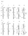
- Fig. 1 shows a schematic representation of the different opening phases (0, I, II, III and IV) two exemplary embodiments A and B of the platform door system 1 according to the invention.
- a platform door system 1 is schematically between the Track body 3 and the platform 4 shown in plan view.
- a barrier 10 exists from individual shut-off elements 12 of constant width 13, each in both directions are movable. With 13a the center distance between the shut-off elements is designated, i.e. the width 13 is plus the clear distance between an adjacent one Shutoff.
- Two locking and guide pins 14 are one on each top Shut-off element 12 provided. These locking and guide bolts 14 are in one fixed guide rail 16 introduced. There is also a second one parallel to the track body Provide guide rail 16 in which the shut-off elements can be moved.
- the shut-off elements 12 are aligned along the edge of the platform.
- the Shut-off elements 12 are locked by the locking and guide bolts 14.
- the Barrier 10 is closed, a passage from the area of the platform to the area Track body is not possible - even unintentionally.
- the platform area 4 is through the locked barrier 10 particularly pressure protected, so that even fast moving trains Station can pass.
- phase I the shut-off elements are unlocked, i.e. that the locking and Guide bolts 14 have been withdrawn from the fixed locking position.
- the Shutdown 10 is still closed, but is no longer as extremely pressure protected as in phase 0.
- shut-off elements 12 are removed from the fixed guide rail 16 on the free guide rail 16 '. This is preferably done over short, in plan Offset devices lying perpendicular (that is to say transversely) to the guide rail 16 ', particularly prefers short rail elements.
- the barrier 10 is still closed; de Shut-off elements are now ready to be offset parallel to one another to release an opening become.
- phase III predetermined shut-off elements along the free guide rail 16 'shifted to create a preselected opening pattern.
- the barrier 10 has openings 5 between the platform 4 and the Track body area 3.
- phase IV the entire platform door system 1 along the platform edge Offset distance 9 shifted. It is possible that the barrier 10 around the Offset path 9 via an additional rail 16.2 underneath (not shown) is moved.
- Phases 0 to IV interact as follows when a train enters: At passing trains the platform door system 1 is in phase 0, is locked and secured against pressure. In normal operation, it is sufficient if the platform door system 1 is is in the unlocked state of phase I. If a train is expected to stop, then The platform door system 1 changes to the state of phase II. The change from phase I II is preferably accompanied acoustically and / or visually. So it makes sense, the introduction phase II with acoustic warning signals such as beeps and orange lights. When the incoming train is almost rolled out, the platform door system 1 goes into phase III transferred, i.e. that the shut-off elements 12 open at the predetermined locations.
- the openings 5 of the barrier 10 and the are then at a standing train opening doors of the train opposite. If the train missed its ideal stop, is in the optional phase IV the barrier 10 to the corresponding malfunction of the Train, i.e. around the offset distance 9 - corrected. This is preferably done slowly and in the train's coasting phase, i.e. while this along the barrier in the station slides and rolls out.
- the individual phases 0 to IV are generally identical to those of the Embodiment A.
- the shut-off elements are on the two Guide rails 16 'and 16 "offset. This makes it possible to close each shut-off element move.
- This has the advantage in particular in phase III that it is possible to wait where the train actually stops and then the door system open according to the real location of the train without one slipped train would have to make up the entire barrier 10.
- FIG. 2a shows an opening image of a further exemplary embodiment of the invention Platform door system shown.
- This is a platform door system that manages with only one guide rail 16.
- the individual shut-off elements 12 are at Opening the barrier 10 to the right and to the left and pulled apart openings 5 are left at predetermined positions.
- the emerging on both sides Excess shut-off elements are either beyond the length of the station moved further along the track body into a stowage area 18 or into a corresponding one provided magazine 19 spent.
- FIG. 2b shows a barrier 10 according to the invention, in which the individual Shut-off elements 12 are placed on a rail 16 'and the opening pattern according to a of the embodiments of FIG. 1 can be generated.
- this preferred Embodiment can be dispensed with a storage area 18 or a magazine 19.
- platform barriers 10a are advantageous provided that can be opened for maintenance purposes for the operating personnel in the Operation preferably remain closed.
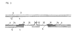
- FIG. 3 shows a schematic illustration of two opening phases of the exemplary embodiments of the platform door system according to the invention shown in FIG. 1.
- a Opening image generated in which the coupling 32 of the train 30 with a shut-off element 12 is covered to also cover this danger area.
- the remaining Barrier elements 12 adapt to the door picture of the standing train.
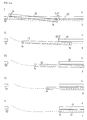
- FIG. 4a, b and c are schematic representations of the different opening phases three embodiments of shut-off elements 12 of the invention Platform door system 1 shown.
- shut-off element 12 pivoting of the shut-off element 12 along a curve (dashed line shown).
- a first phase I the shut-off element 12 becomes light rotated about its central axis until its front edge is behind the rear edge of the Neighboring element 12 'is located, and then in phases II to V behind adjacent shut-off element 12 'pivoted. This eliminates any risk of injury to Avoided passengers.
- facings 17 are preferably additionally provided do not allow that when pivoting the shut-off elements 12 objects in the minimal swivel range. Facings 17 are preferred It is planned to achieve pressure tightness in phase 0.
- shut-off element 12 is tilted about a central axis and then behind that adjacent shut-off element 12 'moved. This is particularly advantageous when on there is sufficient space on the platform side and in the track area.
- Fig. 4c it is shown how the shut-off element 12 first perpendicular to the line along the Barrier 10 is displaced in order to then parallel to the adjacent barrier element 12 ' to be moved.
- shut-off elements 12 and drive devices or motors 23 show a preferred combination of shut-off elements 12 and drive devices or motors 23.
- Each drive device with motor 23 can either unlock or move two elements 12.
- the motors 23 1 and 23 3 move the shut-off elements 12b and 12c by a maximum of one shut-off element width to the left and right after unlocking the locking devices 14.
- motor 23 (x) or motor 23 (x + 1) comes into action.
- the shut-off element 12 (y) can be moved either to the left or to the right.
- the motor thus has a physically favorable position for moving the elements 12.
- Fig. 4e the embodiment of Fig. 4d is in detail for a shut-off element 12 (y) in Interaction with the shut-off elements 12 (y-1) and 12 (y + 1) shown.
- FIG. 5 is a plan view of an embodiment of the invention Platform door system with a sinusoidal groove structure shown as a guide.
- the Shut-off elements 12 are here in sinusoidal groove structures of the guide rail 16 introduced and can be directly along this sinusoidal guide rail be moved.
- Fig. 6a is a side view of an embodiment of shut-off elements 12 of the Platform door system 1 according to the invention in the open state. This Embodiment corresponds to that of Fig. 4b.
- the shut-off elements 12 are first through a rotary motion pivoted about its central axis and then behind the neighboring one Shut-off elements 12 'pushed.
- the platform door system 1 of FIG. 6a is perpendicular to the cross section Track body and platform shown.
- the shut-off element 12 is in one Guide device 16 suspended.
- Locking bolts 14 are on the shut-off element 12 provided to anchor the shut-off element 12 in the guide device 16.
- the Guide device 16 extends to the clearance profile of the train 33, which the Borderline of the clearance profile in the drawing as a dashed line. 6a thus remains for the individual Shut-off elements 12 enough space to behind the guide device 16 adjacent shut-off elements in the space between the clearance profile of the train 33 and the non-shifted shut-off elements 12 to be moved.
- Fig. 7 shows a plan view of drive devices to demonstrate the possible Types of drives for opening a door leaf or moving a shut-off element. 7 is divided into FIGS. 7a to 7d.
- Fig. 7a is a barrier 10 consisting of individual shut-off elements 12 according to the present invention.
- the single ones Shut-off elements 12 each have two locking devices 14.
- Fig. 7b the shut-off elements 14 are shown with a drive facial expression.
- Drive wheels 24 are from the motor 23 via a drive transmission means 25, for example one Timing belt, driven.
- Deflection rollers 28 span the range of motion of the individual Drive elements on.
- Pins 26 are inserted into a latching device 29.
- the motor 23, the shut-off element 12, which is provided for opening, can be provided via a toothed belt 25 grasp and move so far that the required opening width is released.
- Fig. 7c it is shown how a shut-off element 12 by means of the drive wheel 24 and the Timing belt 25 has been moved behind an adjacent shut-off element. Is preferred the maximum opening width occurring is represented by two shut-off elements 12.
- a platform door system has thus been provided that flexibly opens images for can create different door pictures and trains and compensates for the slipping effect.
Claims (15)
- Système de portes pour quai de gare (1), comportant une obturation (10) qui comprend des éléments d'obturation (12) susceptibles d'être alignés le long d'un corps de voie (3) et/ou d'un quai de gare (4), les éléments d'obturation (12) étant mobiles les uns par rapport aux autres sur deux rails (16, 16') écartés l'un de l'autre, de manière à pouvoir être amenés du moins en partie en chevauchement mutuel, grâce à quoi des ouvertures prédéterminées librement définissables (5) peuvent être formées le long du corps de voie (3) et/ou du quai de gare (4), les éléments d'obturation (12) étant mobiles le long des rails (16, 16') dans les deux directions de telle sorte que dans le cas où le train a manqué son point d'arrêt idéal, l'obturation peut être corrigée par rattrapage de l'erreur de position correspondante du train, caractérisé en ce que les éléments d'obturation (12) présentent chacun des dispositifs de verrouillage (14) et des dispositifs d'étanchement (15), les dispositifs de verrouillage (14) servant à verrouiller de façon détachable les éléments d'obturation (12) dans les rails (16, 16'), et les dispositifs d'étanchement (15) servant à étancher des éléments d'obturation voisins (12) les uns par rapport aux autres.
- Système de portes pour quai de gare (1) selon la revendication 1, caractérisé en ce que les éléments d'obturation (12) sont en forme de panneau, en particulier en ce que les éléments d'obturation (12) sont de forme rectangulaire.
- Système de portes pour quai de gare (1) selon l'une des revendications précédentes, caractérisé en ce que les éléments d'obturation (12) contiennent des matériaux transparents, en particulier en ce que les éléments d'obturation (12) contiennent principalement du verre et/ou des acrylates et sont constitués en particulier complètement en matériaux transparents.
- Système de portes pour quai de gare (1) selon l'une des revendications précédentes, caractérisé en ce que les éléments d'obturation (12) sont susceptibles d'être décalés les uns par rapport aux autres, en particulier perpendiculairement à une ligne le long du corps de voie (3) et/ou du quai de gare (4).
- Système de portes pour quai de gare (1) selon l'une des revendications précédentes, caractérisé en ce qu'au moins un élément d'obturation est réalisé de manière à pouvoir être basculé et/ou escamoté et/ou tiré vers le haut.
- Système de portes pour quai de gare (1) selon l'une des revendications précédentes, caractérisé en ce que l'obturation (10) comprend des éléments d'obturation (12) de différentes largeurs (13).
- Système de portes pour quai de gare (1) selon la revendication 1, caractérisé en ce que le dispositif de verrouillage (14) est un goujon et le dispositif d'étanchement (15) est un bourrelet en matière plastique susceptible d'être évasé.
- Système de portes pour quai de gare (1) selon l'une des revendications précédentes, caractérisé en ce qu'il est prévu un dispositif de commande (20) qui pilote des dispositifs d'entraínement (21) qui peuvent décaler et/ou déplacer les éléments d'obturation (12) dans une position prédéterminée.
- Système de portes pour quai de gare (1) selon l'une des revendications précédentes, caractérisé en ce que les éléments d'obturation (12) peuvent être pourvus d'une identification, en particulier qu'ils peuvent prendre une couleur prédéterminée dans au moins une zone prédéterminée.
- Système de portes pour quai de gare (1) selon l'une des revendications précédentes, caractérisé en ce qu'il est prévu une unité de saisie (22) via laquelle on peut choisir préalablement une image prédéterminée d'ouvertures (5).
- Système de portes pour quai de gare (1) selon la revendication 10, caractérisé en ce que l'unité de saisie (22) est alimentée en signaux d'informations qui correspondent à des caractéristiques et/ou à l'occupation d'un train et/ou à l'occupation du quai de gare (4).
- Système de portes pour quai de gare (1) selon la revendication 11, caractérisé en ce que les signaux d'informations sont obtenues via un appareil lecteur de code à barres en avant du quai de gare (4), et/ou
en ce que les signaux d'informations sont obtenus via un système de surveillance dans le train, et/ou
en ce que les signaux d'informations sont entrés via un dispositif de saisie, en particulier un clavier ou un tableau graphique. - Système de portes pour quai de gare (1) selon l'une des revendications précédentes, caractérisé en ce qu'il est prévu des dispositifs structurels (7, 8) en avant et/ou en arrière du quai de gare par lesquels on peut séparer l'espace des voies, en particulier les séparer hermétiquement.
- Procédé pour commander des éléments d'obturation (12) d'une obturation (10) d'un système de portes pour quai de gare (1) selon l'une des revendications précédentes, qui comprend les étapes suivantes :on déplace les éléments d'obturation individuels (12) de telle sorte qu'ils sont amenés en chevauchement mutuel au moins partiellement, grâce à quoi on produit une image d'ouvertures prédéterminée qui correspond aux portes qui s'ouvrent d'un train arrivé ; on corrige tous les éléments d'obturation par rattrapage d'une erreur de position du train.
- Procédé selon la revendication 14, comprenant l'étape préalable suivante :on décale les éléments d'obturation individuels (12) les uns par rapport aux autres.
Applications Claiming Priority (3)
| Application Number | Priority Date | Filing Date | Title |
|---|---|---|---|
| DE19803991 | 1998-02-02 | ||
| DE19803991A DE19803991C2 (de) | 1998-02-02 | 1998-02-02 | Flexibles Bahnsteigtürensystem |
| PCT/EP1999/000672 WO1999038747A1 (fr) | 1998-02-02 | 1999-02-02 | Systeme de portes souple pour quai de gare |
Publications (2)
| Publication Number | Publication Date |
|---|---|
| EP1053159A1 EP1053159A1 (fr) | 2000-11-22 |
| EP1053159B1 true EP1053159B1 (fr) | 2002-05-15 |
Family
ID=7856378
Family Applications (1)
| Application Number | Title | Priority Date | Filing Date |
|---|---|---|---|
| EP99932409A Expired - Lifetime EP1053159B1 (fr) | 1998-02-02 | 1999-02-02 | Systeme de portes souple pour quai de gare |
Country Status (10)
| Country | Link |
|---|---|
| US (1) | US6360668B1 (fr) |
| EP (1) | EP1053159B1 (fr) |
| JP (1) | JP2002501856A (fr) |
| CN (1) | CN1099975C (fr) |
| AU (1) | AU3252599A (fr) |
| CA (1) | CA2319802C (fr) |
| DE (2) | DE19803991C2 (fr) |
| ES (1) | ES2173751T3 (fr) |
| HK (1) | HK1033566A1 (fr) |
| WO (1) | WO1999038747A1 (fr) |
Cited By (1)
| Publication number | Priority date | Publication date | Assignee | Title |
|---|---|---|---|---|
| DE102021110320B3 (de) | 2021-04-22 | 2022-07-07 | Cambaum Gmbh | Nachrüstbare Bahnhofsüberdachung mit integriertem Passagier-Leitsystem |
Families Citing this family (37)
| Publication number | Priority date | Publication date | Assignee | Title |
|---|---|---|---|---|
| EP1398239A1 (fr) * | 2002-07-20 | 2004-03-17 | Michael Voggenauer | Signalisation de la distance de sécurité pour les bords des quais de gare |
| EP1382505A1 (fr) * | 2002-07-20 | 2004-01-21 | Michael Voggenauer | Signalisation de la distance de sécurité pour les bords des quais de gare |
| JP4353683B2 (ja) * | 2002-07-31 | 2009-10-28 | 株式会社日立製作所 | プラットホームドア制御装置 |
| JP4279072B2 (ja) * | 2003-07-18 | 2009-06-17 | 三菱重工業株式会社 | プラットホーム上の可動柵 |
| JP4312074B2 (ja) * | 2004-02-18 | 2009-08-12 | 株式会社日立製作所 | プラットホームドア装置 |
| DE102004045558B3 (de) † | 2004-09-15 | 2005-09-08 | Siemens Ag | Verfahren und Einrichtung zum koordinierten Betrieb von Fahrzeugtüren schienen- oder spurgebundener Fahrzeuge und korrespondierenden Bahnsteigleitsystemen, insbesondere Bahnsteigtüren |
| US20080098924A1 (en) * | 2005-02-14 | 2008-05-01 | Sung Moo Han | Safety Device for Train Platforms |
| GB2436152B (en) * | 2006-03-17 | 2011-05-04 | Knorr Bremse Rail Systems | Platform screen doors |
| GB2442054B (en) * | 2006-09-18 | 2012-02-29 | Knorr Bremse Rail Systems Uk Ltd | Platform screen door |
| US20100043664A1 (en) * | 2006-10-03 | 2010-02-25 | Kaba Gilgen Ag | Gap-Bridging Device for Train Platforms |
| FR2907747B1 (fr) * | 2006-10-30 | 2008-12-26 | Regie Autonome Transports | Dispositif pour combler une lacune entre un quai et un vehicule ferroviaire |
| US7784406B2 (en) * | 2007-05-11 | 2010-08-31 | Chisena Michael P | Train-to-platform gap mitigator |
| ITTO20070396A1 (it) * | 2007-06-06 | 2008-12-07 | Oclap Srl | Barriera di accesso per banchine di stazioni ferroviarie |
| FR2918339A1 (fr) * | 2007-07-02 | 2009-01-09 | Alstom Transport Sa | Vehicule ferroviaire et dispositif d'acces audit vehicule |
| US7721653B1 (en) * | 2007-11-19 | 2010-05-25 | Lamass Burgess | Combined subway wall and door assembly and associated method |
| DE102009021505B4 (de) * | 2009-05-15 | 2012-12-13 | Jürgen Rauch | Bodengeführtes flexibles Barrieren- und Tür-System |
| DE202009009550U1 (de) * | 2009-07-10 | 2010-11-18 | Crown Technologies Gmbh | Vorrichtung zum Verwalten, Aufnehmen und/oder Abgeben von Wertgegenständen |
| JP5311313B2 (ja) * | 2010-12-03 | 2013-10-09 | 国立大学法人 東京大学 | 乗降位置可変型ホームドアの列車への対応付け装置及び乗降位置可変型ホームドアの構成決定装置 |
| KR101276143B1 (ko) | 2011-08-31 | 2013-06-18 | 서울특별시도시철도공사 | 스크린 도어 수 제어 시스템 |
| JP2014004962A (ja) * | 2012-06-26 | 2014-01-16 | Mitsubishi Electric Corp | ホーム扉装置 |
| US9452761B2 (en) | 2013-05-13 | 2016-09-27 | Overhead Door Corporation | Platform screen gate system |
| CN104176067B (zh) * | 2014-09-16 | 2017-10-31 | 中铁第四勘察设计院集团有限公司 | 适应所有列车车型的站台安全门 |
| JP6705005B2 (ja) * | 2016-05-09 | 2020-06-03 | ライザー,タル | 列車プラットホーム配置型安全システム |
| US10648235B2 (en) | 2016-08-15 | 2020-05-12 | The Boeing Company | Work stand configurable for different work areas |
| DE102017200432B4 (de) | 2017-01-12 | 2022-08-18 | Audi Ag | Verfahren zum Betreiben eines Sicherheitssystems für ein Kraftfahrzeug und Sicherheitssystem |
| CN108792901B (zh) * | 2017-05-10 | 2020-06-23 | 福建北大高科发展有限公司 | 一种安全防坠垂直电梯 |
| JP7179567B2 (ja) * | 2018-10-05 | 2022-11-29 | 三菱重工交通・建設エンジニアリング株式会社 | ホームドア制御装置 |
| CN109436016A (zh) * | 2018-12-25 | 2019-03-08 | 韩开敏 | 沿途不停站的智能化高速铁路系统 |
| DE102019208183A1 (de) * | 2019-06-05 | 2020-06-18 | Thyssenkrupp Ag | Aufzuganlage mit verfahrbarer Schachttür |
| CN111547070B (zh) * | 2020-05-25 | 2021-02-26 | 成都唐源电气股份有限公司 | 一种基于套叠式活动单元的高铁站台门 |
| CN112832614B (zh) * | 2021-01-05 | 2023-02-10 | 中车株洲电力机车有限公司 | 一种车辆站台用柔性屏蔽门及其控制方法 |
| CN112441024B (zh) * | 2021-01-29 | 2021-04-09 | 成都唐源电气股份有限公司 | 基于车型投影分布的站台门设计方法及高铁站台门 |
| CN113027277B (zh) * | 2021-03-16 | 2022-05-10 | 南京工程学院 | 一种基于门扇内外压差的关门力自适应控制系统 |
| CN113137161B (zh) * | 2021-04-14 | 2022-11-18 | 永旭(上海)通讯科技有限公司 | 一种安全屏蔽门 |
| CN113602296A (zh) * | 2021-09-18 | 2021-11-05 | 方大智创科技有限公司 | 一种站台滑动门系统 |
| RU2771395C1 (ru) * | 2021-10-22 | 2022-05-04 | Валерий Иванович Паутов | Станционное платформенное раздвижное ограждение метрополитена |
| CN114394115B (zh) * | 2021-12-29 | 2023-10-13 | 浙江中控技术股份有限公司 | 一种多车型通用轨道站台门安全定位系统及控制方法 |
Family Cites Families (12)
| Publication number | Priority date | Publication date | Assignee | Title |
|---|---|---|---|---|
| DE1580862A1 (de) * | 1967-01-27 | 1970-07-16 | August Bauereiss | Einrichtung fuer Bahnhoefe,insbesondere Schnellbahnhoefe und Haltestellen von Schnellbahnen oder U-Bahnen |
| DE2462031A1 (de) * | 1974-05-30 | 1975-12-18 | City Bahn Gmbh | Station fuer automatische bahn |
| US4048755A (en) * | 1976-06-14 | 1977-09-20 | Evans Products Company | Full length door arrangement for railway house car |
| DE3132296A1 (de) * | 1981-08-12 | 1983-03-03 | Gerhard Dipl.-Volksw. 1000 Berlin Kuban | Sicherheitstrennwand auf den bahnsteigen mit korrespondierenden schiebetueren |
| DE3214602A1 (de) * | 1982-04-20 | 1983-10-20 | Andreas 3520 Grebenstein Dangloff | Transportsystem |
| GB8709929D0 (en) * | 1987-04-27 | 1987-06-03 | Westinghouse Brake & Signal | Railway-platform door systems |
| GB2244076A (en) * | 1990-05-14 | 1991-11-20 | Jeremy Ralph Shadbolt | Automatic railway platform barrier |
| US5295441A (en) * | 1991-07-31 | 1994-03-22 | Kawasaki Jukogyo Kabushiki Kaisha | Sliding door apparatus for platform |
| US5253589A (en) * | 1991-07-31 | 1993-10-19 | Kawasaki Jukogyo Kabushiki Kaisha | Folding door apparatus for a railway platform |
| DE9211206U1 (fr) * | 1992-08-18 | 1992-10-29 | Siemens Ag, 8000 Muenchen, De | |
| US5669588A (en) * | 1996-08-26 | 1997-09-23 | Goldsmith; Michael A. | Motion barrier |
| US6105905A (en) * | 1999-01-25 | 2000-08-22 | Spence; Roy | Railway gate system |
-
1998
- 1998-02-02 DE DE19803991A patent/DE19803991C2/de not_active Expired - Fee Related
-
1999
- 1999-02-02 JP JP2000530004A patent/JP2002501856A/ja active Pending
- 1999-02-02 AU AU32525/99A patent/AU3252599A/en not_active Abandoned
- 1999-02-02 US US09/601,182 patent/US6360668B1/en not_active Expired - Fee Related
- 1999-02-02 CN CN99802625A patent/CN1099975C/zh not_active Expired - Fee Related
- 1999-02-02 WO PCT/EP1999/000672 patent/WO1999038747A1/fr active IP Right Grant
- 1999-02-02 CA CA002319802A patent/CA2319802C/fr not_active Expired - Fee Related
- 1999-02-02 EP EP99932409A patent/EP1053159B1/fr not_active Expired - Lifetime
- 1999-02-02 ES ES99932409T patent/ES2173751T3/es not_active Expired - Lifetime
- 1999-02-02 DE DE59901441T patent/DE59901441D1/de not_active Expired - Lifetime
-
2001
- 2001-04-11 HK HK01102603A patent/HK1033566A1/xx not_active IP Right Cessation
Cited By (2)
| Publication number | Priority date | Publication date | Assignee | Title |
|---|---|---|---|---|
| DE102021110320B3 (de) | 2021-04-22 | 2022-07-07 | Cambaum Gmbh | Nachrüstbare Bahnhofsüberdachung mit integriertem Passagier-Leitsystem |
| EP4079993A1 (fr) | 2021-04-22 | 2022-10-26 | Cambaum GmbH | Toiture pour gare pourvue de système intégré de guidage des passagers |
Also Published As
| Publication number | Publication date |
|---|---|
| AU3252599A (en) | 1999-08-16 |
| DE59901441D1 (de) | 2002-06-20 |
| CN1099975C (zh) | 2003-01-29 |
| CN1289295A (zh) | 2001-03-28 |
| CA2319802A1 (fr) | 1999-08-05 |
| DE19803991A1 (de) | 1999-08-05 |
| JP2002501856A (ja) | 2002-01-22 |
| DE19803991C2 (de) | 2002-01-31 |
| US6360668B1 (en) | 2002-03-26 |
| HK1033566A1 (en) | 2001-09-07 |
| EP1053159A1 (fr) | 2000-11-22 |
| WO1999038747A1 (fr) | 1999-08-05 |
| ES2173751T3 (es) | 2002-10-16 |
| CA2319802C (fr) | 2008-03-18 |
Similar Documents
| Publication | Publication Date | Title |
|---|---|---|
| EP1053159B1 (fr) | Systeme de portes souple pour quai de gare | |
| EP1735199B1 (fr) | Dispositif de commande d'une porte d'acces aux quais montee sur la voie de communication d'un vehicule guide sur rails | |
| EP2802500A1 (fr) | Système de porte de quai, procédé de fonctionnement d'un système de porte de quai et dormant pour un système de porte de quai | |
| EP2380833B1 (fr) | Déflecteur de pneu pour le guidage d'un camion | |
| DE2710296C3 (de) | Belüftungsverfahren für einen Tunnel, der von Zügen mit mehreren Maschinen durchfahren wird, und Vorrichtung zur Durchführung des Verfahrens | |
| DE1104985B (de) | Rollplattenvorrichtung zum Schliessen von OEffnungen oben offener Raeume ortsfester oder beweglicher Anlagen in Fahrzeugen | |
| WO2014106581A1 (fr) | Portière de véhicule ferroviaire | |
| DE3738302A1 (de) | Fahrzeug fuer die personenbefoerderung | |
| EP3663158A1 (fr) | Système de marche pour un véhicule | |
| DE2547818C2 (de) | Feuerschutzabschluß für eine Öffnung in Wänden oder Decken, welche von einer Förderanlage durchquert wird | |
| AT516582A1 (de) | Seilbahnanlage | |
| WO2017118699A1 (fr) | Dispositif porte et procédé de fonctionnement d'un dispositif porte | |
| WO2013092164A1 (fr) | Couplage entre porte de cabine et porte palière | |
| EP0367883A1 (fr) | Wagon pour le transport des véhicules | |
| DE4429403C2 (de) | Verfahren zum Behandeln von sich überlagernden Durchrutschwegen | |
| DE102019208183A1 (de) | Aufzuganlage mit verfahrbarer Schachttür | |
| DE1505974C3 (de) | Transportvorrichtung, insbesondere fur den Personenverkehr | |
| DE102012109584A1 (de) | Fahrzeug mit Brandschutzeinrichtung | |
| DE2916721C2 (de) | Vorrichtung zum Transport von Frachtbehältern | |
| EP3293069A1 (fr) | Procédé et remontée mécanique destinée au transport des personnes | |
| DE3744184C2 (fr) | ||
| DE102022110255A1 (de) | Rettung von Passagieren aus einer defekten Aufzugskabine oder Aufzuganlage | |
| EP4238850A1 (fr) | Plate-forme de travail pour travaux sur une zone de toit d'un véhicule, en particulier sur une zone de toit d'un véhicule électrifié, et dispositif de retenue doté d'au moins une telle plate-forme de travail | |
| DE102019130449A1 (de) | System für eine Passagier-Plattform zur Sicherung der Passagiere | |
| DE3150777C1 (de) | Feuerschutzabschluß im Zuge von bahngebundenen Förderanlagen |
Legal Events
| Date | Code | Title | Description |
|---|---|---|---|
| PUAI | Public reference made under article 153(3) epc to a published international application that has entered the european phase |
Free format text: ORIGINAL CODE: 0009012 |
|
| 17P | Request for examination filed |
Effective date: 20000706 |
|
| AK | Designated contracting states |
Kind code of ref document: A1 Designated state(s): CH DE ES FR GB IT LI |
|
| GRAG | Despatch of communication of intention to grant |
Free format text: ORIGINAL CODE: EPIDOS AGRA |
|
| 17Q | First examination report despatched |
Effective date: 20010905 |
|
| GRAG | Despatch of communication of intention to grant |
Free format text: ORIGINAL CODE: EPIDOS AGRA |
|
| GRAH | Despatch of communication of intention to grant a patent |
Free format text: ORIGINAL CODE: EPIDOS IGRA |
|
| GRAH | Despatch of communication of intention to grant a patent |
Free format text: ORIGINAL CODE: EPIDOS IGRA |
|
| GRAA | (expected) grant |
Free format text: ORIGINAL CODE: 0009210 |
|
| AK | Designated contracting states |
Kind code of ref document: B1 Designated state(s): CH DE ES FR GB IT LI |
|
| REG | Reference to a national code |
Ref country code: GB Ref legal event code: FG4D Free format text: NOT ENGLISH Ref country code: CH Ref legal event code: EP |
|
| REG | Reference to a national code |
Ref country code: CH Ref legal event code: NV Representative=s name: BUECHEL, KAMINSKI & PARTNER PATENTANWAELTE ESTABLI |
|
| REF | Corresponds to: |
Ref document number: 59901441 Country of ref document: DE Date of ref document: 20020620 |
|
| ET | Fr: translation filed | ||
| GBT | Gb: translation of ep patent filed (gb section 77(6)(a)/1977) |
Effective date: 20020720 |
|
| REG | Reference to a national code |
Ref country code: ES Ref legal event code: FG2A Ref document number: 2173751 Country of ref document: ES Kind code of ref document: T3 |
|
| PLBE | No opposition filed within time limit |
Free format text: ORIGINAL CODE: 0009261 |
|
| STAA | Information on the status of an ep patent application or granted ep patent |
Free format text: STATUS: NO OPPOSITION FILED WITHIN TIME LIMIT |
|
| 26N | No opposition filed |
Effective date: 20030218 |
|
| REG | Reference to a national code |
Ref country code: CH Ref legal event code: PFA Owner name: RAUCH, JUERGEN Free format text: RAUCH, JUERGEN#HELENE-WEBER-ALLEE 15#80637 MUENCHEN (DE) -TRANSFER TO- RAUCH, JUERGEN#HELENE-WEBER-ALLEE 15#80637 MUENCHEN (DE) |
|
| PGFP | Annual fee paid to national office [announced via postgrant information from national office to epo] |
Ref country code: CH Payment date: 20140324 Year of fee payment: 16 |
|
| PGFP | Annual fee paid to national office [announced via postgrant information from national office to epo] |
Ref country code: ES Payment date: 20140324 Year of fee payment: 16 Ref country code: IT Payment date: 20140327 Year of fee payment: 16 |
|
| REG | Reference to a national code |
Ref country code: FR Ref legal event code: PLFP Year of fee payment: 17 |
|
| REG | Reference to a national code |
Ref country code: CH Ref legal event code: PL |
|
| PG25 | Lapsed in a contracting state [announced via postgrant information from national office to epo] |
Ref country code: LI Free format text: LAPSE BECAUSE OF NON-PAYMENT OF DUE FEES Effective date: 20150228 Ref country code: CH Free format text: LAPSE BECAUSE OF NON-PAYMENT OF DUE FEES Effective date: 20150228 |
|
| PGFP | Annual fee paid to national office [announced via postgrant information from national office to epo] |
Ref country code: GB Payment date: 20150827 Year of fee payment: 17 Ref country code: DE Payment date: 20150831 Year of fee payment: 17 |
|
| PGFP | Annual fee paid to national office [announced via postgrant information from national office to epo] |
Ref country code: FR Payment date: 20150827 Year of fee payment: 17 |
|
| PG25 | Lapsed in a contracting state [announced via postgrant information from national office to epo] |
Ref country code: IT Free format text: LAPSE BECAUSE OF NON-PAYMENT OF DUE FEES Effective date: 20150202 |
|
| REG | Reference to a national code |
Ref country code: ES Ref legal event code: FD2A Effective date: 20160330 |
|
| PG25 | Lapsed in a contracting state [announced via postgrant information from national office to epo] |
Ref country code: ES Free format text: LAPSE BECAUSE OF NON-PAYMENT OF DUE FEES Effective date: 20150203 |
|
| REG | Reference to a national code |
Ref country code: DE Ref legal event code: R119 Ref document number: 59901441 Country of ref document: DE |
|
| GBPC | Gb: european patent ceased through non-payment of renewal fee |
Effective date: 20160202 |
|
| REG | Reference to a national code |
Ref country code: FR Ref legal event code: ST Effective date: 20161028 |
|
| PG25 | Lapsed in a contracting state [announced via postgrant information from national office to epo] |
Ref country code: GB Free format text: LAPSE BECAUSE OF NON-PAYMENT OF DUE FEES Effective date: 20160202 Ref country code: DE Free format text: LAPSE BECAUSE OF NON-PAYMENT OF DUE FEES Effective date: 20160901 Ref country code: FR Free format text: LAPSE BECAUSE OF NON-PAYMENT OF DUE FEES Effective date: 20160229 |