EP3663158A1 - Système de marche pour un véhicule - Google Patents
Système de marche pour un véhicule Download PDFInfo
- Publication number
- EP3663158A1 EP3663158A1 EP19209542.0A EP19209542A EP3663158A1 EP 3663158 A1 EP3663158 A1 EP 3663158A1 EP 19209542 A EP19209542 A EP 19209542A EP 3663158 A1 EP3663158 A1 EP 3663158A1
- Authority
- EP
- European Patent Office
- Prior art keywords
- vehicle
- rotating column
- step system
- plate
- tread plate
- Prior art date
- Legal status (The legal status is an assumption and is not a legal conclusion. Google has not performed a legal analysis and makes no representation as to the accuracy of the status listed.)
- Pending
Links
Images


Classifications
-
- B—PERFORMING OPERATIONS; TRANSPORTING
- B61—RAILWAYS
- B61D—BODY DETAILS OR KINDS OF RAILWAY VEHICLES
- B61D23/00—Construction of steps for railway vehicles
- B61D23/02—Folding steps for railway vehicles, e.g. hand or mechanically actuated
-
- B—PERFORMING OPERATIONS; TRANSPORTING
- B60—VEHICLES IN GENERAL
- B60R—VEHICLES, VEHICLE FITTINGS, OR VEHICLE PARTS, NOT OTHERWISE PROVIDED FOR
- B60R3/00—Arrangements of steps or ladders facilitating access to or on the vehicle, e.g. running-boards
- B60R3/02—Retractable steps or ladders, e.g. movable under shock
Definitions
- Such pedal systems are mainly used in vehicles for the transportation of people.
- it can be used on road vehicles (e.g. buses) or rail vehicles (e.g. trams, subways, local and long-distance trains).
- Pedal systems are generally used to simplify getting in and out of such a vehicle, so they serve as an aid to entry. While a vehicle is stopped at a holding platform, for example a platform, the vehicle is in its rest position, so that the passengers can enter or leave the vehicle. It is almost inevitable that there is a gap in the door area between the outside of the vehicle and the holding platform or platform. Otherwise there would inevitably be material contact between the outside of the vehicle and the holding platform or platform, which could lead to damage to the vehicle, for example in the form of sheet metal or paint damage.
- the step system according to the invention is not restricted to use in a rail vehicle stopping at platforms, as it were a bus platform if the step system is used in a bus.
- step systems that are extended or unfolded in the direction of the stop or platform when the vehicle is idle, is a way to reduce the gap size between the vehicle and the platform or platform.
- a tread system can be designed, for example, as a tread plate or step and absorbs the weight of the passengers when passengers get on or off.
- step systems with step plates or step surfaces made of metal are suitable.
- the treads can be provided with structures or mats that exert an anti-slip effect and reduce the risk of slipping for the passenger when getting on and off.
- flexible tread systems are also known, for example that discloses DE 10 2015 213 650 A1 a bridge element which is elastically deformable in parts or as a whole to bridge a gap between the floor of a rail vehicle and a platform.
- step systems are also suitable for leveling the height between the height of the passenger compartment and the stop or platform. If the step system is designed as a sliding step, the sliding step can additionally be lowered or raised to the level of the holding platform or platform.
- the tread systems can also be designed such that they rest directly on the holding platform or platform in the stopping position of the vehicle.
- Pedal systems based on sliding or folding steps are usually retracted and extended by (electro) motor drives that are provided for the respective step system, for example in the WO 2014/106581 A1 described for the example of a folding step system.
- the drive motors for the door leaves and the folding step can be controlled and regulated via a common door control device.
- a retractable door step arrangement for bridging a gap between a passenger compartment and an adjacent platform is also known.
- the door step arrangement there is composed of a running board part and a connecting part.
- the connecting part is with a retraction mechanism for moving the door step back and forth to the neighboring platform.
- the retraction mechanism is operated by an electric motor and moves the door step assembly from a retracted to a projecting position.
- a sliding step for rail vehicles which has a step cassette and an extension with a step surface which can be accommodated and displaceably mounted at least in sections in the step cassette.
- a drying chamber sealed on all sides and sealed against the ingress of moisture and dirt, is provided inside the step cassette, in which a drive motor and a control unit are arranged.
- a dedicated drive for the step system means that a number of electronic components are installed in the area of the step system. Cleaning them regularly is essential on the one hand for sufficient functionality and on the other hand to ensure operational safety. Especially in view of the fact that dirt and moisture can accumulate in the floor area of a vehicle door, ie on the border from the vehicle interior to the vehicle exterior, it is essential to clean such a drive regularly. This is also associated with regular work and costs. This problem does not arise with specially sealed drives (see, for example, the disclosure content of the DE 102 35 871 A1 ), however, such "sealed" drives must also be regularly subjected to additional maintenance.
- a further disadvantage of the common step systems equipped with their own drive is that they can only be replaced with relatively great effort. This is because they must either be removed together with the drive or separated from it.
- quick interchangeability is desirable especially for those components that are subjected to permanent stress or strain.
- Pedal systems that are subjected to treading loads on passengers almost every time the vehicle is stopped represent a prominent example of a permanently loaded component that should be replaced after a certain operating time or if it is damaged.
- the object of the present invention is to provide a step system for a vehicle, in particular a rail vehicle, which enables simplified maintenance, cleaning and interchangeability of the step system.
- the step plate of a rotary column is connected via a joint arrangement with at least, and that on the hinge arrangement, a rotary motion of the rotary column is transferred into the linear movement of the pedal plate.
- the step system for a vehicle on which the invention is based is particularly suitable for use in a rail vehicle, for example a local or long-distance train for passenger transport.
- the step system interacts with a pivoting sliding door having at least one door leaf, the door leaf of which is at least partially pivoted about a rotating column connected to the door leaf when opening and closing. Accordingly, an axis of rotation extends along the rotating column, about which the door leaf is at least partially pivoted.
- the step system according to the invention can cooperate with a single-leaf swivel sliding door, but preferably with a double-leaf swivel sliding door.
- both door leaves of the swivel sliding door are consequently at least partially pivoted about a rotating column connected to the respective door leaf when opening and closing.
- a rotating column is therefore assigned to each of the door leaves.
- the tread system comprises a tread plate which can be moved reversibly from a retracted position towards an extended position by means of a linear movement along an axis of displacement.
- reversible displaceability means that the tread plate can be displaced both from the retracted position in the direction of the extended position and from the extended position in the direction of the retracted position.
- the displacement of the tread plate from the retracted position in the direction of the extended position is brought about by the rotary movement of the at least one rotating column that takes place when the pivoting sliding door is opened.
- the displacement of the tread plate from the extended position to the retracted position is brought about by the rotary movement of the at least one rotating column that takes place when the pivoting sliding door is closed.
- the step plate is primarily a sliding step.
- the tread plate can also be designed in the manner of a tread bar.
- the step system comprises a guide device arranged on the vehicle, in which the step plate is slidably mounted.
- the tread plate is connected to at least one rotating column via a joint arrangement.
- the tread plate is preferably connected to the respective rotating columns via two separate articulated arrangements.
- a rotary movement of the rotating column can be transferred into the linear movement of the tread plate via the joint arrangement (s).
- a rotation of the rotating columns thus causes the tread plate to be displaced along the displacement axis when the door leaves are pivoted at least partially.
- the step system proposed by the present invention is that an (electro) motor drive provided specifically for the step system can be dispensed with.
- the step system can be extended and retracted via the mechanics already present on the pivoting sliding door system or the drive there for executing the pivoting and sliding movement of the door leaves.
- the mechanical rotary movement of the rotating column (s) is translated into a linear movement of the tread plate.
- the rotating column (s) and tread plate are thus set in motion by a common drive.
- the step system according to the invention is particularly suitable for use with double-leaf swivel sliding door systems, but does not rule out use with single-leaf swivel sliding doors.
- the door leaves or door leaves which can be moved from a closed position into an open position by means of a drive device, are an essential component of such a double-leaf swivel sliding door system.
- the two door leaves of a two-leaf pivoting sliding door are generally each fastened to a vertically extending rotating column by means of suitable pivoting levers.
- the rotating column is preferably connected to the vehicle via an electromechanical drive device and a bearing point.
- the door leaves are guided in a manner known per se relative to a door frame or relative to the vehicle by a guide unit, in particular in order to allow the sliding component during the pivoting sliding movement.
- a separate drive device can be provided for each door leaf, but the rotary columns of both door leaves can also be driven with a common drive device.
- rotary columns can be rotated about an axis of rotation, for example with an electromechanical drive device.
- the axis of rotation coincides with the longitudinal axis of the rotating column.
- a rotation of the rotating column causes a rotation and / or displacement of the door leaf assigned to the respective rotating column.
- the door leaves open and close uniformly and synchronously. Simultaneously or downstream of the pivoting movement of the door leaves, these can be moved along the vehicle's longitudinal axis by means of a guide unit.
- the door leaves with guide elements eg rollers
- the use of sliding guides is also known.
- the door leaves When opening a two-leaf pivoting sliding door, the door leaves are moved synchronously and uniformly away from each other when opening along the longitudinal axis of the vehicle, i.e. they are moved in the opposite direction. When closing, however, the door leaves move towards each other synchronously and uniformly.
- the step system according to the invention interacts with the above-described swivel sliding door system in that the step plate is extended from a retracted position when the door leaves are opened in order to reduce the gap between the vehicle and the platform and to provide a step area for the passenger.
- This process is reversible, i.e. the step system is moved from the extended position back to the retracted position when the door leaves are closed.
- Step systems - which are known to be designed as sliding step systems or folding step systems - often have their own electromotive drive. According to the invention, such an additional drive for the step system can be dispensed with.
- step system reduces the space requirement of the step system, which enables a compact and modular design.
- a modular design enables the step system to be replaced and removed easily and quickly, for example for the purpose of repair or due to irreparable damage. If an additional drive is not required, cleaning of the step system is also simplified. By dispensing with an additional drive for the step system, there is no need to use a large number of additional electronic components and cabling, which in principle make cleaning the step system more difficult.
- the step plate forms a sliding step.
- the extension of the step plate can be easily controlled by using a sliding step system.
- the extension of the tread plate depends on the rotation of the rotating column, that is to say on the angle of rotation.
- the tread plate is advantageously in its fully extended position when the door leaves of the pivoting sliding door are fully open.
- the angle of rotation of the rotating column required for a complete opening of the door leaves corresponds to the angle of rotation of the rotating column which causes the tread plate to be displaced into its fully extended position.
- the step plate is in the extended position, provided that the at least one rotary column is rotated by an angle of rotation, preferably by an angle of rotation of 40 °, starting from a rotary position corresponding to the closed position of the at least one door leaf 60 °, and particularly preferably by an angle of rotation of 50 °.
- a rotating column rotated by 50 ° corresponds to the step plate being fully extended. It should be noted that the information about the angle of rotation includes technically determined tolerance ranges.
- the step plate can also only be partially extended, for example if the distance to the holding platform is less than the maximum extension distance of the step system. In this case the angle of rotation of the rotating column would be less than 50 °.
- An advantageous embodiment can lie in the fact that distance sensors are provided in the tread plate or on the vehicle which detect the distance of the vehicle from the holding platform. Depending on the detected distance, a desired extension distance can be implemented in terms of control and regulation technology.
- a decoupling device can be provided between the rotating column and the tread plate, which is set up to prevent the rotating column from blocking when a defined extension of the tread plate and / or when the tread plate is struck on a holding platform. This is crucial in order to ensure that the door leaves open fully when the step plate is not fully extended. Otherwise, the door opening process could be interrupted or blocked, for example, when the tread plate hits the holding platform or platform.
- the decoupling device can be mechanical in nature and can be formed in the region of the joint arrangement, and the decoupling device can also be designed on the rotating column.
- the tread plate of the local tread system in the extended position also provides a tread surface between an outside of the vehicle and a holding platform, for example a platform or bus platform.
- a passenger can use the tread when boarding or alighting as a step-in aid and fully load his body weight.
- the tread serves accordingly as an intermediate step for easier entry into the vehicle.
- a gap prevailing between the vehicle and the holding platform can be reduced from a first gap width to a second gap width.
- a smaller gap width reduces the risk that a passenger entering or exiting stumbles over the gap when getting in or out, gets caught in the gap or is otherwise injured. This inherently improves ferry passengers' safety when boarding and alighting.
- the guide device of the step system claimed by the present invention can also be arranged below the step plate in the region of the pivoting sliding door system and can be connected to the vehicle in a fixed position.
- a positionally fixed connection of the guide device to the vehicle brings about a stable and secure mounting of the tread plate, in particular while driving.
- the guide device can be equipped with an additional locking device, which means that additional securing and securing of the step plate - for example while driving - can be guaranteed.
- the tread plate is arranged below a floor covering of the vehicle interior. As a result, the tread plate is not visible to the passenger who is in the passenger compartment of the vehicle during the journey and can therefore not represent any optical-aesthetic impairment for the passenger.
- the arrangement of the tread plate below the floor covering ensures that the tread plate is not exposed to any treading stress while driving and is protected from moisture and dirt.
- the sliding axis of the tread plate can, as in known tread systems, extend transversely to the longitudinal direction of the vehicle. This ensures that the tread plate can be displaced in the direction of a holding platform or platform running parallel to the vehicle, that is to say transversely to the longitudinal direction of the vehicle.
- the guide device of the tread system claimed by the invention can also be a slide bearing.
- the slide bearing can be composed of guide rails arranged fixed to the vehicle and guide elements arranged on the tread plate, which engage in the guide rails. By engaging the guide elements in the guide rails, the tread plate is secured against the action of forces acting transversely to the axis of displacement, in particular with regard to a possible shift in position.
- the slide bearing is composed of a guide bush and a guide rail guided in the guide bush, the guide bush being arranged fixed to the vehicle on the tread plate and the guide rail or vice versa.
- the slide bearing can also be designed in another known manner, for example as a floating support bearing. The selection of the specific design of the plain bearing can be adapted to the structural conditions of the vehicle.
- the guiding device can also be designed as a roller bearing.
- Such bearings are also known in principle, but not in connection with the step system according to the invention.
- a roller holder including suitable rollers can be used be provided, wherein the rollers can engage in a vehicle-mounted roller guide, for example in the form of guide rails.
- the joint arrangement comprises a connecting member, a connecting shaft, a first and a second universal joint, and a linkage connecting the universal joints.
- the connecting member can be a flat metal product.
- the connecting link can be made from sheet metal. Production as a forged or cast part can be considered as a production method.
- the connecting member In the area of its first end and its second end, the connecting member can have a first hole opening or a second hole opening.
- the first hole opening is preferably designed as an elongated hole.
- the hole openings can be punched into the connecting member after production or after reshaping.
- the connecting member is connected to the tread plate in the region of the first hole opening.
- a bolt or connecting flange can be provided on the step plate, which engages in the first hole opening of the connecting member.
- the longitudinal axis of the connecting link extends orthogonally to the axis of rotation of the rotating column. In other words, the link extends in a horizontal plane.
- the connecting shaft is arranged perpendicular to the connecting member and engages with one end in the second hole opening of the connecting member. In this area, the connecting shaft is non-rotatably connected to the connecting member.
- the first universal joint is with another end of the connecting shaft and with a first end Linkage connected.
- the second universal joint is connected to a second end of the linkage and to the rotating column.
- the linkage can be inclined relative to the connecting shaft by an angle, preferably by an angle of 30 ° -60 °, more preferably by an angle of 40 ° -50 °, and particularly preferably by an angle of 45 °.
- the arrangement of universal joints, linkage and connecting shaft serves to compensate for the angle between the rotating column and connecting link.
- the arrangement also serves to transfer the torque of the rotating column to the connecting member and thus to translate the rotational movement of the rotating column into the linear movement of the tread plate.
- a rotary movement of the rotating columns when the door leaves are opened is transmitted to the connecting shaft via the arrangement of the first and second universal joint and the linkage, which is consequently also set into a rotary movement.
- a rotary movement of the connecting shaft leads to a rotation of the connecting member.
- the link rotates with the link shaft.
- a rotary movement of the rotating column or the connecting shaft operatively connected to it leads to a rotating movement of the connecting member.
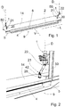
- the Figure 1 illustrates the pedal system according to the invention for a vehicle in a schematic view.
- a step system is used as an example, as is used in pivoting sliding door systems of rail vehicles. It should be expressly emphasized at this point that the step system according to the invention is not limited to use in rail vehicles.
- pivoting sliding door systems together with the step systems according to the invention can also be used, for example, in other vehicles for local and long-distance public transport, for example in buses.
- such a step system serves to reduce a gap existing when the rail vehicle is stopped between the door area and a holding platform or platform and to provide a step surface 8 for the passenger when entering or exiting the vehicle or out of the vehicle.
- the risk of a passenger entering or leaving the gap S between the door and the platform (see 5, 6 ) stumbles, gets caught or gets injured, is reduced by the step system that reduces the gap width.
- Swivel sliding door systems can be single-leaf or double-leaf, that is, they can have either one or two door leaves.
- the door system according to the invention is particularly suitable for use with double-leaf door systems.
- the door leaves In the closed position, the door leaves are usually in the vehicle wall, so they are flush with the outside of the vehicle.
- the opening and closing process is primarily carried out when the vehicle is stopped.
- the door leaves can each be attached to a vertically extending rotating column 1 by means of suitable pivot levers.
- the rotary column 1 can be connected to the vehicle, for example, at its upper end via an electromechanical drive device.
- the respective door leaves are guided in a known manner against a door frame or against the vehicle by a guide unit.
- the rotating column 1 can be rotated about an axis of rotation D by the electromechanical drive device.
- the axis of rotation D coincides with the longitudinal axis of the rotating column 1 which extends in the vertical direction.
- the lower part of the rotary column 1 together with the axis of rotation D is in the Figures 1 and 2 indicated.
- a rotation of the rotating column 1 causes - via the swivel arms - a rotation of the respective door leaf. Simultaneously or downstream of the pivoting movement of the door leaf, these can be moved along the longitudinal axis L of the vehicle by means of a guide unit.
- the door leaves When opening a two-leaf pivoting sliding door, the door leaves are moved away from each other when opening along the longitudinal axis L of the vehicle, so they are moved in the opposite direction. When closing, however, the door leaves move towards each other.
- tread systems cooperate with the above-described pivoting sliding door system in that the tread systems are extended from a retracted position when the door is opened in order to reduce the gap between the vehicle and the holding platform 10 and to provide a tread surface 8 for the passenger.
- the reduction in the width of such a gap S by virtue of a step system is shown schematically in FIGS Figures 5 and 6 reproduced. Further details will be discussed in more detail later.
- the step systems - which are known as sliding step system or Folding step system can be carried out - its own electric motor drive. However, this entails the disadvantages explained at the outset.
- the drive device can be, for example, an electromotive drive unit which carries out a combined swivel-slide movement of the respective door leaf.
- Each door leaf can be assigned its own drive unit, or the rotating columns of the two door leaves are driven by a common drive unit.
- the Figure 1 shows the step system according to the invention in its extended state, ie a step plate 2 belonging to the step system is in the direction of a (in Figure 1 Not shown landing stage 10, but see illustration after Figures 5 and 6 ) extended.
- the tread plate 2 is in an extended position, ie the door leaves (not shown) of the pivoting sliding door system are in the open state.
- the tread plate 2 provides a tread surface 8, which serves as a boarding aid for a passenger. When entering or exiting the vehicle, the passenger can position his foot on the tread 8 and load the tread 8 with his body weight.
- the step surface 8 thus provides an intermediate step area between the holding platform 10 and the vehicle.
- the tread plate 2 has its greatest extent along the vehicle longitudinal axis L.
- the tread plate 2 can be designed in the area of the tread surface 8 as a tread bar.
- the tread plate 2 closes with a strip 4 which likewise extends along the longitudinal axis L of the vehicle.
- the strip 4 lies opposite the holding platform 10 in the holding position of the vehicle.
- the step plate 2 shown is designed as a sliding step plate and is moved from a retracted position by a sliding movement along a displacement axis V running transversely to the longitudinal axis L of the vehicle (see Figure 2 ) in an extended position ( Figure 1 ) emotional.
- the tread plate 2 or tread surface 8 is covered in the retracted position by a floor covering 14 of the vehicle interior; conversely, this means that the tread plate 2 is arranged below the floor covering 14 (see in particular Figure 2 ).
- a floor pan 5 is provided below the tread plate 2 and has guide rails 16 extending along the displacement axis V ( 3, 4 ) along which the tread plate 2 is movably guided. From the synopsis of Figures 1 to 4 it becomes clear that two rotating columns 1 of the (Not shown) pivoting sliding door system are operatively connected to the tread plate 2. Rotation of the rotating columns 1 when the door leaves of the pivoting sliding door system are opened leads, according to the invention, to an extension movement of the tread plate 2 in the direction of the holding platform 10. A rotating movement of the rotating columns 1 is converted into a translational linear movement of the tread plate. This is accomplished by means of a shifting mechanism to be explained in more detail.
- the Figure 3 shows a schematic plan view of a partial section of the tread system according to the invention in its retracted position.
- a partial section of the step system on which the invention is based is also shown in a schematic plan view, but in its extended position (cf. also here Fig. 1 ).
- a connecting member 6 - this can also be referred to as a connecting hook - is attached to the tread plate 2 with a first end 18. With a second end 19, the connecting member is operatively connected to the rotating column 1.
- a first hole opening 31 and a second hole opening 32 are provided at the first end 18 and at the second end 19 of the connecting member 6.
- the connecting member 6 is fastened to the tread plate 2 via the first hole opening 31, for example via a bolt which engages in the first hole opening 31 and is fastened to the tread plate 2.
- the first hole opening 31 can be designed as an elongated hole.
- a connecting shaft 20 extending perpendicular to the connecting member 6 engages with its one end 41 in the second hole opening 32 of the connecting member 6 and is rotatably connected to it.
- the rotationally fixed connection can be implemented, for example, via a screw connection or weld connection.
- the other end 42 connects the connecting shaft 20 to the rotary column 1 via a first universal joint 21, a second universal joint 22 and a linkage 50 arranged between the first and second universal joint 21, 22 (reference is made to the detailed illustration in FIG Figure 2 ).
- the first universal joint 21, the second universal joint 22 and the linkage 50 represent an angle-compensating element between the rotating column 1 and the connecting shaft 20, which is connected to the connecting member 6 and stands upright.
- a rotary movement of the rotary column 1 or rotary columns 1 carried out when the door leaves are opened is transmitted to the connecting shaft 20 via the arrangement of the first and second universal joint 21, 22 and the linkage 50, which consequently is also set in a rotary movement. Due to the rotationally fixed connection between the connecting shaft 20 and the connecting member 6, a rotary movement of the connecting shaft 20 leads to a rotation of the connecting member 6. The connecting member 6 then rotates with the connecting shaft 20. Starting from the in Fig. 3 shown, retracted position of the tread plate 2, a rotational movement of the rotating column 1 or the connecting shaft 20 operatively connected thereto leads to a rotational movement of the connecting member 6 in the direction of the arrow.
- both rotating columns 1 are operatively connected to the step plate 2 (see also the illustration in FIG Figure 1 ).
- the connecting links 6 are arranged in mirror symmetry and are each connected to an end region of the step plate 2.
- the tread plate 2 has a U-shaped shape when viewed from above.
- the connecting members 6 are connected to the leg sections 52 of the U-shaped tread plate 2, the leg sections 52 integrally connecting to the central section 54 providing the tread surface 8.
- a guide device 3 for movably guiding the tread plate 2 is provided in the region of the floor pan 5.
- the guide device 3 comprises guide rails 16 which are mounted on the floor pan 5 and are thus arranged fixed to the vehicle.
- Guide elements (not shown) arranged on the tread plate 2 engage therein.
- the guide elements engaging in the rails 16 slide along the guide rails 16 during the displacement movement of the tread plate 2. This can be done on the guide rails a guide groove may be provided.
- Guide elements can be designed, for example, in the form of a guide pin or a guide bar.
- the guide elements can be integrally formed on the tread plate 2, or can be detachably connected to it, for example via a screw connection.
- the guide device 3 is preferably designed as a slide bearing, but in principle a configuration as a roller bearing is also possible. Another design of the slide bearing is also possible, for example as a floating support bearing.
- the tread system serves to reduce a gap S between the vehicle in the holding position or the vehicle exterior 9 and the holding platform 10, namely of a gap width S 1 (this gives the distance between the vehicle exterior 9 and the outer edge facing the vehicle of the holding platform 10 in the unopened state of the door leaves) to a gap width S 2 (this represents the distance between the outer edge of the holding platform 10 facing the vehicle and the bar 4 of the tread plate 2).
- the gap width S 2 is calculated from the difference between the gap width S 1 and the length of the actual extension path W corresponds to the step plate 2 of the step system.
- Figure 5 shows the state of the tread system with the tread plate 2 in the retracted position
- Figure 6 shows the step system with the step plate 2 in the (at least partially) extended position. Since the distance of the holding platform 10 from the vehicle can vary due to different local conditions of train stations, it may be provided that the step plate 2 is not fully extended.
- distance sensors can be provided in the step plate 2 or on the vehicle, which detect the distance of the vehicle from the holding platform 10.
- a desired extension W can be implemented in terms of control and regulation technology. This can be combined with a mechanical decoupling device between the rotating column 1 and the connecting shaft 20.
Applications Claiming Priority (1)
| Application Number | Priority Date | Filing Date | Title |
|---|---|---|---|
| DE202018106885.7U DE202018106885U1 (de) | 2018-12-04 | 2018-12-04 | Trittsystem für ein Fahrzeug |
Publications (1)
| Publication Number | Publication Date |
|---|---|
| EP3663158A1 true EP3663158A1 (fr) | 2020-06-10 |
Family
ID=68583251
Family Applications (1)
| Application Number | Title | Priority Date | Filing Date |
|---|---|---|---|
| EP19209542.0A Pending EP3663158A1 (fr) | 2018-12-04 | 2019-11-15 | Système de marche pour un véhicule |
Country Status (2)
| Country | Link |
|---|---|
| EP (1) | EP3663158A1 (fr) |
| DE (1) | DE202018106885U1 (fr) |
Cited By (2)
| Publication number | Priority date | Publication date | Assignee | Title |
|---|---|---|---|---|
| CN112046518A (zh) * | 2020-08-26 | 2020-12-08 | 王小龙 | 一种用于轨道交通列车的安全隔离装置 |
| CN113963490A (zh) * | 2021-10-20 | 2022-01-21 | 陶金鑫 | 基于不动产登记和地形图数据综合管理平台的数据采集终端 |
Families Citing this family (1)
| Publication number | Priority date | Publication date | Assignee | Title |
|---|---|---|---|---|
| DE202022101380U1 (de) | 2022-03-15 | 2023-06-16 | Bode - Die Tür Gmbh | Einstiegssystem für ein Fahrzeug, insbesondere Schienenfahrzeug |
Citations (10)
| Publication number | Priority date | Publication date | Assignee | Title |
|---|---|---|---|---|
| DE857813C (de) * | 1951-02-21 | 1952-12-01 | Deutsche Bundesbahn | Bewegliche Einsteigetritte fuer Eisenbahnfahrzeuge |
| DE2057365A1 (de) * | 1970-11-21 | 1972-05-25 | Linke Hofmann Busch | Klapptritt fuer schienengebundene Personenfahrzeuge |
| FR2226298A1 (fr) * | 1973-04-18 | 1974-11-15 | Linke Hofmann Busch | |
| JPS59220448A (ja) * | 1983-05-30 | 1984-12-11 | 徳永 陽一 | 車両乗降口安全装置 |
| FR2637245A1 (fr) * | 1988-10-04 | 1990-04-06 | Tokunaga Youichi | Dispositif de securite pour l'acces a un vehicule tel qu'un wagon de chemin de fer |
| DE10235871A1 (de) | 2002-07-31 | 2004-02-12 | Pintsch Bamag Antriebs- Und Verkehrstechnik Gmbh | Schiebetritt |
| DE102004009900A1 (de) | 2003-02-28 | 2004-12-16 | Bombardier Transportation Gmbh | Einziehbare Türstufenanordnung |
| WO2014106581A1 (fr) | 2013-01-04 | 2014-07-10 | Siemens Aktiengesellschaft | Portière de véhicule ferroviaire |
| CN105818824A (zh) * | 2015-09-17 | 2016-08-03 | 成都明日星辰科技有限公司 | 一种用于轨道交通安全踏板的机械智能联动装置 |
| DE102015213650A1 (de) | 2015-07-20 | 2017-01-26 | Bombardier Transportation Gmbh | Schienenfahrzeug mit Brückenelement zur Spaltüberbrückung zwischen einer Tür und einem Bahnsteig |
-
2018
- 2018-12-04 DE DE202018106885.7U patent/DE202018106885U1/de active Active
-
2019
- 2019-11-15 EP EP19209542.0A patent/EP3663158A1/fr active Pending
Patent Citations (10)
| Publication number | Priority date | Publication date | Assignee | Title |
|---|---|---|---|---|
| DE857813C (de) * | 1951-02-21 | 1952-12-01 | Deutsche Bundesbahn | Bewegliche Einsteigetritte fuer Eisenbahnfahrzeuge |
| DE2057365A1 (de) * | 1970-11-21 | 1972-05-25 | Linke Hofmann Busch | Klapptritt fuer schienengebundene Personenfahrzeuge |
| FR2226298A1 (fr) * | 1973-04-18 | 1974-11-15 | Linke Hofmann Busch | |
| JPS59220448A (ja) * | 1983-05-30 | 1984-12-11 | 徳永 陽一 | 車両乗降口安全装置 |
| FR2637245A1 (fr) * | 1988-10-04 | 1990-04-06 | Tokunaga Youichi | Dispositif de securite pour l'acces a un vehicule tel qu'un wagon de chemin de fer |
| DE10235871A1 (de) | 2002-07-31 | 2004-02-12 | Pintsch Bamag Antriebs- Und Verkehrstechnik Gmbh | Schiebetritt |
| DE102004009900A1 (de) | 2003-02-28 | 2004-12-16 | Bombardier Transportation Gmbh | Einziehbare Türstufenanordnung |
| WO2014106581A1 (fr) | 2013-01-04 | 2014-07-10 | Siemens Aktiengesellschaft | Portière de véhicule ferroviaire |
| DE102015213650A1 (de) | 2015-07-20 | 2017-01-26 | Bombardier Transportation Gmbh | Schienenfahrzeug mit Brückenelement zur Spaltüberbrückung zwischen einer Tür und einem Bahnsteig |
| CN105818824A (zh) * | 2015-09-17 | 2016-08-03 | 成都明日星辰科技有限公司 | 一种用于轨道交通安全踏板的机械智能联动装置 |
Cited By (2)
| Publication number | Priority date | Publication date | Assignee | Title |
|---|---|---|---|---|
| CN112046518A (zh) * | 2020-08-26 | 2020-12-08 | 王小龙 | 一种用于轨道交通列车的安全隔离装置 |
| CN113963490A (zh) * | 2021-10-20 | 2022-01-21 | 陶金鑫 | 基于不动产登记和地形图数据综合管理平台的数据采集终端 |
Also Published As
| Publication number | Publication date |
|---|---|
| DE202018106885U1 (de) | 2020-03-05 |
Similar Documents
| Publication | Publication Date | Title |
|---|---|---|
| EP0513509B1 (fr) | Ascenseur | |
| EP1772414B1 (fr) | Chasse-pieds pliable auto-bloquant pour cabine d'ascenseur | |
| EP3663158A1 (fr) | Système de marche pour un véhicule | |
| DE19959825C1 (de) | Schiebewand mit mehreren seitlich verschiebbaren Wandelementen | |
| DE2620683A1 (de) | Einstieganordnung fuer ein nahverkehrsfahrzeug | |
| WO2012048759A1 (fr) | Rampe comportant une barrière latérale | |
| DE1104985B (de) | Rollplattenvorrichtung zum Schliessen von OEffnungen oben offener Raeume ortsfester oder beweglicher Anlagen in Fahrzeugen | |
| EP0641701B1 (fr) | Marchepieds pour véhicules ferroviaires | |
| WO2014106581A1 (fr) | Portière de véhicule ferroviaire | |
| WO2000055038A1 (fr) | Cabine de passerelle pour les passagers d'un avion | |
| EP3684667B1 (fr) | Véhicule ferroviaire comprenant un élément de sol mobile au niveau de l'ouverture de la porte | |
| EP3900982A1 (fr) | Système d'entrée pourvu de rabat d'étanchéité accessible | |
| EP0931532A1 (fr) | Rampe pour véhicules | |
| DE102016125785B4 (de) | Türvorrichtung für ein Schienenfahrzeug | |
| DE102015106342A1 (de) | Ein- und Aussteighilfe | |
| EP3583011B1 (fr) | Dispositif et procédé de réalisation d'un accès à niveau pour différentes hauteurs de quais | |
| DE202020105599U1 (de) | Verkehrsleitwand | |
| DE2330900A1 (de) | Vorrichtung zum abstuetzen, sowie zum oeffnen und schliessen von fahrzeug-tueren | |
| EP0253263B1 (fr) | Véhicule à fourgon avec mécanisme de levage | |
| EP3974281B1 (fr) | Dispositif de montée pour un véhicule | |
| EP3702234B1 (fr) | Fixation de porte supplémentaire active dans la zone inférieure du bord de fermeture principal | |
| DE202009006413U1 (de) | Schienenfahrzeug | |
| EP3984853A1 (fr) | Marche coulissante à entrainement passif | |
| DE3335699A1 (de) | Hecktuer an kraftfahrzeugen | |
| DE2338378A1 (de) | Trittstufenabdeckung fuer mehrstufige einstiege an schienenfahrzeugen, insbesondere reisezugwagen in verbindung mit einer aussenschiebetuer |
Legal Events
| Date | Code | Title | Description |
|---|---|---|---|
| PUAI | Public reference made under article 153(3) epc to a published international application that has entered the european phase |
Free format text: ORIGINAL CODE: 0009012 |
|
| STAA | Information on the status of an ep patent application or granted ep patent |
Free format text: STATUS: THE APPLICATION HAS BEEN PUBLISHED |
|
| AK | Designated contracting states |
Kind code of ref document: A1 Designated state(s): AL AT BE BG CH CY CZ DE DK EE ES FI FR GB GR HR HU IE IS IT LI LT LU LV MC MK MT NL NO PL PT RO RS SE SI SK SM TR |
|
| AX | Request for extension of the european patent |
Extension state: BA ME |
|
| STAA | Information on the status of an ep patent application or granted ep patent |
Free format text: STATUS: REQUEST FOR EXAMINATION WAS MADE |
|
| 17P | Request for examination filed |
Effective date: 20201208 |
|
| RBV | Designated contracting states (corrected) |
Designated state(s): AL AT BE BG CH CY CZ DE DK EE ES FI FR GB GR HR HU IE IS IT LI LT LU LV MC MK MT NL NO PL PT RO RS SE SI SK SM TR |
|
| RAP3 | Party data changed (applicant data changed or rights of an application transferred) |
Owner name: BODE - DIE TUER GMBH |
|
| STAA | Information on the status of an ep patent application or granted ep patent |
Free format text: STATUS: EXAMINATION IS IN PROGRESS |
|
| 17Q | First examination report despatched |
Effective date: 20221004 |