EP3974281B1 - Dispositif de montée pour un véhicule - Google Patents
Dispositif de montée pour un véhicule Download PDFInfo
- Publication number
- EP3974281B1 EP3974281B1 EP21191732.3A EP21191732A EP3974281B1 EP 3974281 B1 EP3974281 B1 EP 3974281B1 EP 21191732 A EP21191732 A EP 21191732A EP 3974281 B1 EP3974281 B1 EP 3974281B1
- Authority
- EP
- European Patent Office
- Prior art keywords
- step plate
- tread plate
- access device
- extension
- pawl
- Prior art date
- Legal status (The legal status is an assumption and is not a legal conclusion. Google has not performed a legal analysis and makes no representation as to the accuracy of the status listed.)
- Active
Links
- 238000006073 displacement reaction Methods 0.000 claims description 82
- 230000033001 locomotion Effects 0.000 claims description 66
- 230000000903 blocking effect Effects 0.000 claims description 5
- 230000001419 dependent effect Effects 0.000 claims 5
- 230000000712 assembly Effects 0.000 claims 1
- 238000000429 assembly Methods 0.000 claims 1
- 238000003780 insertion Methods 0.000 description 4
- 230000037431 insertion Effects 0.000 description 4
- 238000010276 construction Methods 0.000 description 2
- 230000000284 resting effect Effects 0.000 description 2
- 230000005540 biological transmission Effects 0.000 description 1
- 230000009194 climbing Effects 0.000 description 1
- 239000011248 coating agent Substances 0.000 description 1
- 238000000576 coating method Methods 0.000 description 1
- 239000000314 lubricant Substances 0.000 description 1
- 239000000463 material Substances 0.000 description 1
- 230000009347 mechanical transmission Effects 0.000 description 1
- 239000002184 metal Substances 0.000 description 1
- 238000000034 method Methods 0.000 description 1
- 230000001960 triggered effect Effects 0.000 description 1
Images


Classifications
-
- B—PERFORMING OPERATIONS; TRANSPORTING
- B61—RAILWAYS
- B61D—BODY DETAILS OR KINDS OF RAILWAY VEHICLES
- B61D23/00—Construction of steps for railway vehicles
- B61D23/02—Folding steps for railway vehicles, e.g. hand or mechanically actuated
- B61D23/025—Folding steps for railway vehicles, e.g. hand or mechanically actuated electrically or fluid actuated
-
- B—PERFORMING OPERATIONS; TRANSPORTING
- B60—VEHICLES IN GENERAL
- B60R—VEHICLES, VEHICLE FITTINGS, OR VEHICLE PARTS, NOT OTHERWISE PROVIDED FOR
- B60R3/00—Arrangements of steps or ladders facilitating access to or on the vehicle, e.g. running-boards
- B60R3/02—Retractable steps or ladders, e.g. movable under shock
Definitions
- the present invention relates to an boarding device for a vehicle, in particular for a rail vehicle, comprising a linearly displaceable tread plate arrangement, which is formed from a tread plate and an extension unit operatively connected to the tread plate, and a drive unit which is set up to consist of the tread plate and the To move the tread plate arrangement formed by the push-out unit along a displacement axis while executing a displacement movement from a retracted position to an extended position and vice versa.
- a “vehicle” can be understood to mean, in particular, a wheeled or rail-bound vehicle.
- wheeled vehicles can in particular be transport vehicles for passenger transport, for example bus vehicles.
- rail-bound vehicles can also be transport vehicles for passenger transport, for example trams, S-Bahn trains, trains (regional trains, long-distance trains), subways, trams, etc.
- boarding facilities can be used for vehicles of any kind , in which a difference in height or a gap between a handrail and a step in the interior of the vehicle must be overcome when people get in or out. Such a situation can also occur, for example, when an aircraft stops at a gate or the gate's holding platform, which is why boarding facilities can also be used on aircraft.
- boarding devices serve to facilitate entry and exit into a vehicle of the type described above.
- WO 2016/083586 A1 and the EP 2 390 142 A1 sliding step devices and folding step devices are well known.
- Sliding step devices are based on the fact that a step plate is moved back and forth between a retracted and an extended position, in particular along a displacement axis extending in the transverse direction of the vehicle.
- the tread plate In the extended position, the tread plate provides a tread surface through which a person can enter or exit the vehicle.
- the tread plate can be guided in a linearly displaceable manner by means of a guide in a vehicle-side housing or a frame.
- Sliding steps make it easier to get in and out of a vehicle by bridging a gap between the vehicle and a platform (e.g. a platform edge).
- Folding steps (in particular folding steps designed like a ramp) are intended in particular to overcome differences in height between a vehicle interior (e.g. a floor provided there) and a parking platform, but can also be used to bridge a gap between the vehicle and the parking platform.
- the distance between the vehicle and the stop is not constant, but varies depending on the structural conditions of the stop or the specific stopping situation.
- the same can apply to a difference in height between the vehicle and the sidewalk, so that in addition to a possible gap, a certain height difference must also be overcome by a person getting in or out.
- a sliding step can bridge a gap between the platform and the vehicle, but cannot compensate for an existing height difference. Accordingly, barrier-free boarding cannot be ensured in all stopping situations or on all stopping platforms if only a sliding step is provided.
- the present invention is based on the object of providing an boarding device with which safe boarding of people is ensured at different height levels and / or distances between a vehicle and a holding platform, and with which different height levels and / or distances can be flexibly bridged.
- the present invention relates to an boarding device for a vehicle, in particular for a rail vehicle, comprising a linearly displaceable tread plate arrangement which is formed from a tread plate and an extension unit operatively connected to the tread plate, the extension unit having a first and a second extension rail, wherein the first and second extension rails are arranged parallel to one another, and wherein the tread plate is arranged between the first and second extension rails, and a drive unit which is designed to move the tread plate arrangement formed from the tread plate and the extension unit along a displacement axis, executing a displacement movement of one from a retracted position to an extended position and vice versa.
- the access device is characterized by at least one locking means which is designed to block displacement of the extension unit along the displacement axis in the extended position of the tread plate arrangement, and at the same time to release a relative movement between the tread plate and the extension unit, as a result of which the tread plate is relatively can be moved and tilted to the extension unit.
- the boarding device in addition to the sliding step function well known from the prior art, also provides a ramp function, ie one between a vehicle and a vehicle
- a ramp function ie one between a vehicle and a vehicle
- the height difference present on the parking platform can be overcome by the boarding device, so that safe and barrier-free entry and exit into the vehicle is possible even in the event of a parking platform height level below the vehicle floor level.
- the present invention therefore provides an boarding device which, in addition to a classic sliding step function, also provides a ramp function.
- an “boarding device” is to be understood as a device which makes it easier or possible for a person to get in or out of a vehicle.
- the tread plate is subjected to weight when entering or exiting, for example due to the impact of a person climbing on.
- a “vehicle” can be understood to mean in particular a wheeled or rail-bound vehicle.
- Wheeled vehicles can in particular be transport vehicles for passenger transport, for example bus vehicles.
- Rail-bound vehicles can also be transport vehicles for passenger transport, for example trams, S-Bahn trains, trains (regional trains, long-distance trains), subways, trams, etc.
- the linearly displaceable tread plate arrangement is an arrangement of components that are operatively connected to one another, namely the tread plate and the extension unit.
- an active connection is to be understood as meaning that the components belonging to the tread plate arrangement, i.e. the tread plate and the extension unit, are coupled to one another in such a way that both components can be displaced simultaneously when a displacement movement is carried out.
- the tread plate can take the extension unit with it or vice versa.
- the drive unit is connected to the treadle plate or the extension unit, so that through the operative connection of both components, a (at least indirect) transmission of movement to both components can take place, even if the drive unit is directly connected to only one of the components (e.g. the treadle plate).
- the active connection can be provided, for example, by a mechanical active connection means or an active connection mechanism.
- the extension unit is guided in a linearly displaceable manner in a guide device provided on the vehicle via a suitable guide, for example a roller or rail guide.
- the tread plate can also be guided or arranged in a linearly displaceable manner, for example on the underside, via a guide, for example a roller or rail guide, in a guide device provided on the vehicle.
- the drive unit mentioned is preferably connected directly to the tread plate or a component attached to it, for example a tread plate carrier. Due to the active connection provided between the tread plate and the extension unit, the extension unit can be carried along the displacement axis when the tread plate is linearly displaced, i.e. the drive unit can cause a linear displacement of the tread plate and the extension unit along the displacement axis, i.e.
- a mechanical transmission means e.g. a linkage or a drive belt
- the drive unit can in particular be an electric motor drive.
- the displacement of the tread plate and the extension unit when executing the displacement movement of the tread plate arrangement takes place in the same direction and simultaneously.
- the extension unit and tread plate are also moved at the same speed.
- the footplate is designed in such a way that it can bear the weight of one or more people when getting in or out.
- it is not absolutely necessary that the tread plate is fully extended, because even in a position between the retracted position and the extended position of the lying position of the tread plate, it can be used for entry, that is to say it can be stepped on.
- a stopping platform edge may prevent the tread plate from being completely extended to the extended position.
- the tread plate can also be subjected to tread loads in a position that is not fully extended.
- the tread plate can have anti-slip properties, for example by forming a a suitable surface profile, a suitable anti-slip coating or by using an anti-slip mat. Such a design can further increase the sure-footedness of a person getting in or out of the vehicle.
- the access device also has at least one locking means which is designed to block displacement of the extension unit along the displacement axis in the extended position of the tread plate arrangement.
- the displacement movement is blocked both in the direction of the retracted position and in the direction of the extended position.
- a trigger mechanism can be activated, whereby the at least one locking means is activated and thus the blocking of the displacement movement is triggered.
- the locking means assumes a locking position.
- the locking means can be released by a release mechanism and brought into an open position, in which a displacement movement of the tread plate arrangement in the direction of the retracted position is made possible.
- Preferably two blocking means are provided.
- the at least one locking means - in the extended position of the tread plate arrangement - enables a relative movement between the tread plate and the extension unit.
- the tread plate In this position, the tread plate is decoupled from the extension unit in terms of movement. This means that the tread plate can be moved and tilted relative to the extension unit.
- a relative movement between the tread plate and the extension unit is prevented, ie there is no relative displacement or inclination of the tread plate relative to the extension unit.
- the relative movement can be a superimposed displacement and inclination movement, ie the relative movement of the tread plate takes place in the manner of a pivoting-sliding movement with inclination and linear displacement components.
- the tread plate When stopping a vehicle on a sidewalk, the tread plate does not necessarily have to be tilted to the maximum possible angle of inclination. Since the tread plate - depending on the height of the holding platform - can rest on the holding platform, stopping situations can occur in which the tread plate is not inclined by the maximum possible angle of inclination relative to the extension unit, but rather only by a partial inclination angle based on a maximum inclination. In such a case, the angle of inclination is determined by the relative vertical position between the vehicle and the pavement.
- the extension unit has a first and a second extension rail, the first and second extension rails being arranged parallel to one another, and the tread plate being arranged between the first and second extension rails.
- the first and second extension rails extend along respective extension rail axes that are parallel to the displacement axis.
- the first and second extension rails are arranged at a distance from one another (the distance is provided by the tread plate) and are guided in a linearly displaceable manner via a suitable guide, for example a roller or rail guide, in a guide device provided on the vehicle.
- a suitable guide for example a roller or rail guide
- the first and second extension rails form an extension unit and are preferably made of metal or plastic.
- the locking means is a locking pawl which is pivotally mounted on one of the extension rails, in particular about a pivot axis extending in the longitudinal direction of the vehicle.
- the pawl can be pivoted about a pivot axis extending in the longitudinal direction of the vehicle, provided that the access device is arranged in the side area of the vehicle, i.e. is not positioned in the front or rear area.
- the pawl can be pivoted about a pivot axis extending perpendicular to the displacement axis, regardless of the Arrangement position of the boarding facility on the vehicle.
- a pawl is pivotally mounted as a locking means on both the first extension rail and the second extension rail.
- first and second extension rails are preferably designed in the same way, that is, for example, have the same length, width, depth, etc. Certain functional elements, recesses, openings, guide devices, etc. are therefore preferably provided on both extension rails.
- the pawl has a first leg and a second leg, the legs being arranged at an angle to one another.
- the angle can be between 70° and 100°, but in particular 90°.
- the pivot bearing of the pawl is preferably implemented in a connecting section of the first and second legs.
- the respective pawl can be pivotally mounted on a bearing pin arranged on the respective extension rail, so that said bearing pin can engage in a hole opening provided in the connecting section of the pawl.
- the pawl (including its two legs and the connecting section) are preferably designed as a flat product, for example as a metallic flat product.
- the tread plate is guided in a linearly movable manner with a guide element arranged on the tread plate side so that it cannot move in a linearly movable manner in a guide device formed on the first and second extension rail.
- the guide device mentioned is formed on both extension rails, preferably at the same height and in the same longitudinal section.
- the guide elements are each arranged in a section of the tread plate facing the respective extension rail and are connected in a movement-resistant manner to the tread plate or a component connected to it.
- the respective guide element engages (at least partially) in the guide device formed on the respective extension rail.
- the guide devices formed on the extension rails are arranged opposite each other, as are the guide elements.
- the guide device is an elongated hole extending along a longitudinal section of the extension rail, and that the guide element is a guide bolt. Accordingly, a guide pin arranged on a tread plate side facing the first extension rail is guided in an elongated hole formed on the first extension rail or engages at least partially in it. A guide pin arranged on a tread plate side facing the second extension rail is guided in an elongated hole formed on the second extension rail or engages at least partially in it.
- the elongated hole diameter can be adapted to the diameter of the guide pin, so that the guide pin can be moved longitudinally within the elongated hole.
- the respective elongated hole and/or the respective guide pin can be lubricated with a lubricant for friction-reduced guidance.
- the guide pin is an operative connection means between the tread plate and the extension unit. Accordingly, the guide pin can transmit movement between the tread plate and the extension unit. If, for example, a displacement movement in the tread plate is initiated via the drive unit, the displacement movement can also be transmitted to the extension unit (or the extension rails) via the guide pin acting as a driver, so that the tread plate and the extension unit can undergo a displacement movement at the same time.
- the guide pin is set up to strike a first end section of the pawl when the sliding movement of the tread plate arrangement is carried out from the retracted to the extended position and thus to take the extension unit with it.
- the pawl can be in a position in which the guide bolt stops against a first end section of the Pawl enables or is realized.
- the first end section of the pawl can preferably be a leg end of a leg of the pawl.
- both functional elements are arranged statically, ie in a fixed position, relative to one another.
- a displacement movement transmitted to the tread plate by the drive unit can be transmitted to the extension rail. Accordingly, a displacement movement of the extension rails (i.e. the extension unit) can be generated using the drive unit.
- the guide pin is set up to strike a first elongated hole end when the sliding movement of the tread plate arrangement is carried out from the extended to the retracted position and thus to take the extension unit with it.
- the guide pin does not strike the pawl.
- the guide pin which acts as a driver, interacts with the first end of the elongated hole and at this point transmits the driving force generated by the drive unit and initially transmitted to the tread plate to the respective extension rails of the extension unit, so that these can be taken along using the guide pin.
- the pawl in the extended position of the tread plate arrangement abuts against a first stop element which is arranged on the vehicle side in a non-displaceable manner and undergoes a pivoting movement, as a result of which the pawl contacts with its first end section second stop element arranged on the vehicle side in a non-displaceable manner strikes.
- the stop on the first stop element is preferably carried out with a leg end arranged in the area of a second end section of the pawl.
- the described Stop position On the one hand, a displacement of the extension unit in the direction of the retracted position (the decisive factor here is the stop of the first end section of the pawl on the second stop element arranged on the vehicle side) and, on the other hand, beyond the extended position (the decisive factor here is the stop of the second end section of the pawl on the first stop element arranged on the vehicle side).
- the decisive factor here is the stop of the second end section of the pawl on the first stop element arranged on the vehicle side.
- the tread plate is displaced relative to the extension unit.
- the displacement path corresponds to a displacement path of the guide bolt from the first elongated hole end to a second elongated hole end opposite the first elongated hole end.
- the length of the elongated hole therefore determines a displacement amount between the tread plate and the extension unit in the extended position of the extension unit. It should be emphasized that when the tread plate is shifted relative to the extension unit, in addition to the linear displacement, the tread plate also experiences an inclination movement in relation to a plane spanned by the extension unit, in particular a downward inclination movement.
- the guide pin abuts on the second elongated hole end in a maximally inclined position of the tread plate, the pawl in this position simultaneously resting on the guide pin with a bearing section.
- the striking of the guide pin on the second end of the elongated hole prevents further relative displacement or relative inclination of the tread plate relative to the extension unit - which is locked in this position by the pawl.
- the guide pin additionally supports the pawl in this position (by the pawl resting on the guide pin with its bearing section). It can be advantageous if an edge of the first leg of the pawl facing the guide pin has a bevel.
- the bevel allows the guide pin to slide more easily when moving along the slot.
- the bevel is preferably designed in such a way that the first leg tapers in relation to a cutting plane running perpendicular to and along the displacement axis, starting from the first leg end (of the first leg) in the direction of the connecting section arranged between the first and second leg.
- the guide pin is displaced along the elongated hole during the relative movement between the tread plate and the extension unit.
- the guide pin rests on the first elongated hole end. If the tread plate is then moved relative to the extension unit in the extension direction and tilted relative to the extension unit, the guide pin connected to the tread plate is displaced along the elongated hole. In the maximum displacement or tilting position between the tread plate and the extension unit, the guide pin rests on the second end of the slot.
- the tread plate is pivotally mounted relative to the extension unit via the guide pin, with pivoting between the tread plate and extension unit only being possible in the extended position of the extension unit (ie the extension rails).
- the tread plate is pivotably mounted relative to the extension unit via two guide bolts arranged in the side region of the tread plate (i.e. the side regions of the tread plate facing the respective extension rails).
- the respective guide pin can therefore experience a rotational movement within the elongated hole.
- the rotation movement corresponds to the tilting movement of the tread plate.
- the respective elongated holes not only provide longitudinal guides for the guide bolts, but also corresponding pivot bearings. Because the guide bolts - in addition to the previous one Functions described - can also provide a pivot bearing for the tread plate, the provision of an additional pivot bearing device can be dispensed with, so the overall construction can be constructed more compactly and with less use of material.
- the tread plate is connected to the first and second extension rails via a joint arrangement.
- the joint arrangement relates in particular to two joint elements of identical construction, which are designed in the manner of an elongated or rod-shaped flat product, and which are on the one hand on the side regions of the tread plate (i.e. in those areas of the tread plate facing the extension rails) and on the other hand on a front end section facing towards the outside of the vehicle the respective extension rails are articulated.
- the joint elements or latches mediate the tilting movement.
- the joint elements When tilting the tread plate relative to the extension unit, the joint elements are also tilted starting from a position parallel to the extension rails.
- the joint elements can have an elongated hole, in which an engagement element arranged in the end region of the extension rails engages. When tilting the tread plate relative to the extension unit, the elongated hole can slide along the engagement element.
- Such an articulation of the tread plate on the extension unit can be designed in the manner of a crank mechanism.
- the relative movement between the tread plate and the extension unit is a superimposed pivoting-sliding movement, in which the tread plate is relative to the extension unit along the displacement axis over a length corresponding to the length of the elongated hole Amount can be moved, and in which the tread plate can be tilted relative to the extension unit by a maximum angle of inclination determined by the joint arrangements.
- FIG. 1 A first exemplary embodiment of an boarding device according to the invention is shown in a perspective view.
- the boarding facility is used as an entry and exit aid in a vehicle or is integrated into the vehicle.
- the vehicle is a rail vehicle.
- boarding devices are usually arranged in the side area of the vehicle in order to enable people to get on from a holding platform located on the side of the vehicle.
- the boarding device comprises a linearly displaceable step plate arrangement 1, which is composed of a step plate 2 and an extension unit 3 operatively connected to the step plate 2.
- a step load that is to say it is subjected to the weight of the person.
- the tread plate arrangement 1 formed from the tread plate 2 and the extension unit 3 can be displaced along a displacement axis V while executing a displacement movement from a retracted position to an extended position and vice versa.
- the tread plate assembly 1 is positioned in a position between the retracted and extended positions, i.e. partially extended. When the displacement movement is carried out, both components of the tread plate arrangement 1 are displaced along the displacement axis V, regardless of the displacement direction.
- the extension unit 3 is formed from a first extension rail 11 and a second extension rail 12 (see, for example, Fig. 2 ).
- the extension rails 11, 12 are arranged parallel and spaced apart from one another. The distance is provided by the tread plate 2, which is arranged between the first extension rail 11 and the second extension rail 12.
- the “extension rails” marked with reference numbers 11 and 12 form so-called side cheeks, which provide frame elements of the extension unit 3.
- the extension unit 3 is guided with the help of rollers, the rollers running in guide rails of a base frame.
- the access device includes a locking means which is designed to block displacement of the extension unit 3 along the displacement axis V in the extended position of the tread plate arrangement 1. This applies to both displacement in the extension direction A and in the insertion direction E. Reached from the extension rails 11, 12 formed extension unit 3 together with the footplate 2 is in the extended position (see the position of the extension rails in Fig. 2 ), then there is no further displacement of the extension rails 11, 12 in the extension direction A. In this position, displacement of the extension rails 11, 12 in the insertion direction E is also blocked.
- the tread plate 2 on the other hand, is - as in the Figure 2 shown - can be displaced relative to the extension rails 11, 12 in the extension direction A beyond a displacement position assumed in the extended position and can be tilted in relation to the extension rails 11, 12.
- This relative movement which is composed of a displacement and inclination movement, between the tread plate 2 and the extension unit 3 (or the extension rails 11, 12) is released by the locking means when the tread plate arrangement 1 is reached (i.e. the tread plate 2 and the extension unit 3).
- Figure 2 In contrast to Figure 1 , show the Figure 2 i.e. a position in which the extension unit 3 formed from the extension rails 11, 12 is in an extended position.
- the tread plate 2 is inclined relative to the extension unit 3, for example in the direction of a holding platform, not shown.
- the locking means mentioned is in the form of a pawl 5, with a pawl 5 preferably being pivotably mounted on both the first extension rail 11 and the second extension rail 12.
- the pivot mounting of the pawl 5 on the extension rails 11, 12 is particularly clear in the Figures 2 - 4 to recognize.
- the pawl 5 can be pivoted about a pivot axis extending orthogonally to the displacement axis V.
- the pawl 5 has a first leg 21 and a second leg 22, the legs 21, 22 - as in Fig. 4 marked - are arranged at an angle ⁇ to each other.
- the first leg 21 has a bevel 10 on its underside, the function of which will be explained later.
- a guide bolt 7 is connected to both side areas L, E of the tread plate 2.
- the guide bolts 7 therefore represent guide elements arranged on the tread plate side so as to be fixed in motion.
- a respective guide bolt 7 is located in one on the First and second extension rail 11, 12 arranged elongated hole 6 guided in a linearly movable manner.
- the elongated hole 6 therefore provides a guide device. As can be seen from the figures, the elongated hole 6 extends along a longitudinal section of the extension rail.
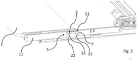
- the pawl 5 When executing a displacement movement of the tread plate arrangement 1 from the retracted towards the extended position (i.e. a displacement movement in the extension direction A, cf. Fig. 1 ), the pawl 5 assumes a position in which the guide pin 7 abuts a first end section 51 of the pawl ( Fig. 3 ). Since the drive unit 4 directly transmits the displacement movement to the tread plate 2, the tread plate 2 takes the extension rails 11, 12 with it through the guide pins 7 abutting on the respective locking pawls 5 when the extension-displacement movement is carried out.
- the guide pin 7 strikes a first elongated hole end 31 ( Fig. 3 ) and thus takes the extension rails 11, 12 (the extension unit 3) with it.
- the stop occurs with a second end section 52 of the pawl 5.
- the pawl 5 undergoes a pivoting movement, as a result of which the pawl 5 abuts with its first end section 51 on a second stop element 42 which is arranged on the vehicle side in a non-displaceable manner.
- This process enables a relative displacement of the respective guide bolts 7 in the elongated holes 6 of the respective extension rails 11, 12 (the Fig.
- the guide pin 7 can be moved longitudinally in the elongated hole 6). If, in the extended position of the tread plate arrangement 1, the extension unit 3 is locked by the pawl 5 with respect to a displacement movement along the displacement axis V and a displacement force is exerted on the tread plate 2 in the extension direction A via the drive unit 4, the tread plate 2 is opposite the extension unit 3 formed by the extension rails 11, 12 is displaced.
- the displacement path is limited by the length of the elongated holes 6, in particular by respective first and second elongated hole ends 31, 32.
- an edge of the first leg 21 of the pawl 5 facing the guide pin 7 has a bevel 10.
- the bevel 10 allows simplified sliding of the guide pin 7 during movement or displacement along the elongated hole 6.
- the bevel 10 is designed such that the first leg 21 is based on a cutting plane perpendicular to and along the displacement axis V, starting from the first leg end 21 (of the first leg) tapers in the direction of the connecting section 23 arranged between the first and second legs 21, 22.
- the tread plate 2 when the tread plate 2 is moved in the extension direction A relative to the extension rails 11, 12, the tread plate 2 also experiences an inclination, namely in the sense of pivoting away.
- the guide bolts 7 mounted in the elongated holes 6 rotate by the amount of inclination.
- the tread plate 2 is connected to the first and second extension rails 11, 12 via a joint arrangement 9.
- the respective joint arrangements 9 include two identical joint elements 13, which on the one hand are on the side areas L, R (see Fig. 2 ) of the tread plate 2 (i.e. in those areas of the tread plate 2 facing the extension rails 11, 12) and on the other hand on a front end section 14 of the respective extension rails 11, 12 facing the outside of the vehicle.
- the joint elements 13 mediate the tilting movement.
- the joint elements 13 are moved from a position parallel to the extension rails 11, 12 ( Fig. 1 , 3 ) also reluctant ( Fig. 2 , 6 ).
- the joint elements 13 can have an elongated hole 15, in which an engagement element 17 arranged in the end region 16 of the extension rails 11, 12 engages.
- the elongated hole 15 can be displaced relative to the engagement element 17, that is, the elongated hole 15 is moved relative to the position-fixed engagement element 17.
- Such an articulation of the tread plate 2 on the extension unit 3 acts in the manner of a crank mechanism when the tread plate 2 is lowered.
- bearing recesses 18 can be formed in the extension rails 11, 12, in which a bearing roller (not shown) arranged on the respective joint elements 13 is mounted in a non-inclined position of the tread plate 2.
- the bearing roller is arranged at that end 19 of the joint element 13, which is opposite an end 20 of the joint element 13 that is articulated to the tread plate 2.
- the joint elements 13 are arranged parallel to the extension rails 11, 12, which is why the bearing roller mentioned is mounted in the bearing recess 18 in such a position.
- the bearing recess 18 is preferably designed in the manner of a half-shell, so that the bearing roller can be easily extended from the bearing recess 18 when the tread plate 2 is lowered.
Landscapes
- Engineering & Computer Science (AREA)
- Mechanical Engineering (AREA)
- Vehicle Step Arrangements And Article Storage (AREA)
Claims (14)
- Dispositif d'accès destiné à un véhicule, notamment à un véhicule ferroviaire, comprenanta. un ensemble (1) de marchepied, placé en étant déplaçable de manière linéaire, qui est constitué d'un marchepied (2) et d'une unité de déployage (3) en interaction avec le marchepied (2), l'unité de déployage (3) comportant un premier et un deuxième rails de déployage (11, 12), le premier et le deuxième rails de déployage (11, 12) étant placés à la parallèle l'un de l'autre, et le marchepied (2) étant placé entre le premier et le deuxième rails de déployage (11, 12),b. ainsi qu'une unité d'entraînement (4), qui est conçue pour déplacer l'ensemble (1) de marchepied constitué du marchepied (2) et de l'unité de déployage (3) le long d'un axe de déplacement (V), en effectuant un mouvement de déplacement d'une position escamotée vers une position déployée et inversement, etc. et au moins un moyen d'arrêt, qui est configuré, dans la position déployée de l'ensemble (1) de marchepied- pour bloquer un déplacement de l'unité de déployage (3) le long de l'axe de déplacement (V),- et simultanément, pour libérer un mouvement relatif entre le marchepied (2) et l'unité de déployage (3), en conséquence de quoi, le marchepied (2) est déplaçable et inclinable par rapport à l'unité de déployage (3).
- Dispositif d'accès selon la revendication 1, caractérisé en ce que le moyen d'arrêt est un cliquet d'arrêt (5), qui est logé de manière à pouvoir pivoter, notamment autour d'un axe de pivotement qui s'étend dans la direction longitudinale du véhicule, sur l'un des rails de déployage (11, 12).
- Dispositif d'accès selon la revendication 2, caractérisé en ce que le cliquet d'arrêt comporte une première branche (21) et une deuxième branche (22), les branches (21, 22) étant placées sous un angle (β) l'une par rapport à l'autre.
- Dispositif d'accès selon l'une quelconque des revendications précédentes, caractérisé en ce que le marchepied (2) est guidé en étant mobile de manière linéaire à l'aide de chaque fois un élément de guidage, placé en étant solidaire en mouvement du côté du marchepied dans un système de guidage conçu sur le premier et le deuxième rails de déployage (11, 12).
- Dispositif d'accès selon la revendication 4, caractérisé en ce que le système de guidage est un trou oblong (6) s'étendant le long d'une section longitudinale du rail de déployage et en ce que l'élément de guidage est un boulon de guidage (7) .
- Dispositif d'accès selon la revendication 5, caractérisé en ce que le boulon de guidage (7) est un moyen d'assemblage actif entre le marchepied (2) et l'unité de déployage (3).
- Dispositif d'accès selon la revendication 6, caractérisé en ce que le boulon de guidage (7) est configuré pour buter, lors de la réalisation du mouvement de déplacement de l'ensemble (1) de marchepied de la position escamotée vers la position déployée sur un premier segment d'extrémité (51) du cliquet d'arrêt (5) et entraîner ainsi l'unité de déployage (3).
- Dispositif d'accès selon la revendication 6 ou 7, caractérisé en ce que le boulon de guidage (7) est configuré pour buter, lors de la réalisation du mouvement de déplacement de l'ensemble (1) de marchepied de la position déployée vers la position escamotée sur une première extrémité (31) du trou oblong et entraîner ainsi l'unité déployage (3).
- Dispositif d'accès selon la revendication 2 ou l'une quelconque des revendications précédentes, dépendant de la revendication 2, caractérisé en ce que, dans la position déployée de l'ensemble (1) de marchepied, le cliquet d'arrêt (5) bute contre un premier élément de butée (41) placé de manière solidaire en déplacement du côté du véhicule et effectue un mouvement de pivotement, suite auquel le cliquet d'arrêt (5) bute par son premier segment d'extrémité (51) sur un deuxième élément de butée (42) placé de manière solidaire en déplacement du côté du véhicule.
- Dispositif d'accès selon la revendication 5 ou l'une quelconque des revendications précédentes, dépendant de la revendication 5, caractérisé en ce que dans une position d'inclinaison maximum du marchepied (2), le boulon de guidage (7) bute sur une deuxième extrémité (32) du trou oblong, dans cette position, le cliquet d'arrêt (5) s'appuyant simultanément par un segment de palier (8) sur le boulon de guidage (7).
- Dispositif d'accès selon la revendication 5 ou l'une quelconque des revendications précédentes, dépendant de la revendication 5, caractérisé en ce que pendant le mouvement relatif entre le marchepied (2) et l'unité déployage (3), le boulon de guidage (7) est déplacé le long du trou oblong (6).
- Dispositif d'accès selon la revendication 5 ou l'une quelconque des revendications précédentes, dépendant de la revendication 5, caractérisé en ce que le marchepied (2) est logé par l'intermédiaire du boulon de guidage (7) en étant susceptible de pivoter par rapport à l'unité déployage (3), un pivotement entre le marchepied (2) et l'unité de déployage (3) étant rendu possible exclusivement dans la position déployée de l'unité de déployage (3).
- Dispositif d'accès selon l'une quelconque des revendications précédentes, caractérisé en ce que le marchepied (2) est assemblé chaque fois par l'intermédiaire d'un ensemble articulé (9) avec le premier et le deuxième rails de déployage (11, 12).
- Dispositif d'accès selon la revendication 5 ou l'une quelconque des revendications précédentes, dépendant de la revendication 5 caractérisé en ce que le mouvement relatif entre le marchepied (2) et l'unité de déployage (3) est un mouvement de déplacement en pivotement superposé, lors duquel le marchepied (2) est déplaçable par rapport à l'unité de déployage (3) le long de l'axe de déplacement (V) d'une valeur correspondant à une longueur du trou oblong (6), et lors duquel le marchepied (2) est inclinable par rapport à l'unité de déployage (3) au maximum de la valeur d'un angle d'inclinaison fixé par les ensembles articulés (9).
Applications Claiming Priority (1)
| Application Number | Priority Date | Filing Date | Title |
|---|---|---|---|
| DE202020105492.9U DE202020105492U1 (de) | 2020-09-25 | 2020-09-25 | Zustiegeinrichtung für ein Fahrzeug |
Publications (3)
| Publication Number | Publication Date |
|---|---|
| EP3974281A1 EP3974281A1 (fr) | 2022-03-30 |
| EP3974281B1 true EP3974281B1 (fr) | 2024-01-17 |
| EP3974281C0 EP3974281C0 (fr) | 2024-01-17 |
Family
ID=77367364
Family Applications (1)
| Application Number | Title | Priority Date | Filing Date |
|---|---|---|---|
| EP21191732.3A Active EP3974281B1 (fr) | 2020-09-25 | 2021-08-17 | Dispositif de montée pour un véhicule |
Country Status (2)
| Country | Link |
|---|---|
| EP (1) | EP3974281B1 (fr) |
| DE (1) | DE202020105492U1 (fr) |
Family Cites Families (6)
| Publication number | Priority date | Publication date | Assignee | Title |
|---|---|---|---|---|
| DE19503079C2 (de) * | 1995-02-01 | 1998-07-09 | Deutsche Waggonbau Ag | Überfahrrampe für Rollstuhlfahrer in Fahrzeugen mit Niederflureinstiegen, insbesondere Reisezugwagen |
| US5832555A (en) * | 1995-02-27 | 1998-11-10 | Ricon Corporation | Compact moveable ramp assembly |
| EP2390142B1 (fr) | 2010-05-31 | 2013-07-31 | Hübner Transportation GbmH | Dispositif destiné à la réception démontable d'une rampe |
| EP3237254B1 (fr) | 2014-11-28 | 2019-02-20 | Gebr. Bode GmbH & Co. KG | Marchepied avec fonction de levage et de rampe |
| EP3156279B1 (fr) | 2015-10-12 | 2019-11-27 | Schmitz Cargobull AG | Vehicule automobile pour le transport de marchandises |
| DE202018102317U1 (de) | 2018-04-25 | 2018-05-14 | Edag Engineering Gmbh | Trittstufenvorrichtung |
-
2020
- 2020-09-25 DE DE202020105492.9U patent/DE202020105492U1/de active Active
-
2021
- 2021-08-17 EP EP21191732.3A patent/EP3974281B1/fr active Active
Also Published As
| Publication number | Publication date |
|---|---|
| EP3974281C0 (fr) | 2024-01-17 |
| DE202020105492U1 (de) | 2022-01-07 |
| EP3974281A1 (fr) | 2022-03-30 |
Similar Documents
| Publication | Publication Date | Title |
|---|---|---|
| EP1772414B1 (fr) | Chasse-pieds pliable auto-bloquant pour cabine d'ascenseur | |
| EP1663700B1 (fr) | Dispositif a memoire pour une glissiere longitudinale d'un siege de vehicule automobile | |
| EP0416539B1 (fr) | Dispositif d'accès pour véhicules automobiles, en particulier pour autobus | |
| DE102006000619B4 (de) | Federbelastete Klinkensperre mit automatischer Rückstellung | |
| EP1378397B1 (fr) | Dispositif et méthode pour le réglage manuel en hauteur d'un plancher de charge de véhicule | |
| DE2620683A1 (de) | Einstieganordnung fuer ein nahverkehrsfahrzeug | |
| DE102009004525B4 (de) | Fangvorrichtung für einen Rollstuhl in einem Fahrzeug, insbesondere Schienenfahrzeug | |
| EP3663158A1 (fr) | Système de marche pour un véhicule | |
| DE19531284A1 (de) | Schienenfahrzeug für den Personenverkehr | |
| EP3974281B1 (fr) | Dispositif de montée pour un véhicule | |
| DE10312466B4 (de) | Ladesystem für einen Laderaum eines Kraftfahrzeuges | |
| EP1595737A2 (fr) | Rampe extensible pour véhicules de transport en commun | |
| EP1615795B1 (fr) | Dispositif de guidage longitudinal pour un siege de vehicule automobile | |
| EP3709945A1 (fr) | Dispositif de seuil de porte pour système d'accès avec marche escamotable pour un véhicule et système d'accès avec marche escamotable présentant un dispositif de seuil de porte | |
| DE102015106342A1 (de) | Ein- und Aussteighilfe | |
| EP4087997B1 (fr) | Dispositif de stationnement équipé d'un ensemble de porte | |
| EP1873004A2 (fr) | Siège de véhicule automobile doté d'un dossier pouvant pivoter automatiquement de la position d'utilisation en position au repos | |
| DE102014211492B4 (de) | Trittstufe für Kraftfahrzeuge | |
| EP1034765A2 (fr) | Dispositif pour faciliter l'entrée et la sortie d'un véhicule des transports publics en particulier un véhicule approchant un perron | |
| DE102004035536B4 (de) | Ladeboden | |
| DE10034008B4 (de) | Einrichtung zur Verstellung und Arretierung eines in Längsrichtung verschiebbaren Sitzes | |
| DE2905509A1 (de) | Foerdereinrichtung fuer wagen | |
| EP0937603A1 (fr) | Dispositif de verrouillage pour un dossier rabattable de véhicule automobile | |
| DE102004022916B3 (de) | Vorrichtung zur Verstellung und/oder Befestigung eines Fahrzeugsitzes | |
| DE102011005238B4 (de) | Arretierbare Rampe |
Legal Events
| Date | Code | Title | Description |
|---|---|---|---|
| PUAI | Public reference made under article 153(3) epc to a published international application that has entered the european phase |
Free format text: ORIGINAL CODE: 0009012 |
|
| STAA | Information on the status of an ep patent application or granted ep patent |
Free format text: STATUS: THE APPLICATION HAS BEEN PUBLISHED |
|
| AK | Designated contracting states |
Kind code of ref document: A1 Designated state(s): AL AT BE BG CH CY CZ DE DK EE ES FI FR GB GR HR HU IE IS IT LI LT LU LV MC MK MT NL NO PL PT RO RS SE SI SK SM TR |
|
| RAP3 | Party data changed (applicant data changed or rights of an application transferred) |
Owner name: BODE - DIE TUER GMBH |
|
| STAA | Information on the status of an ep patent application or granted ep patent |
Free format text: STATUS: REQUEST FOR EXAMINATION WAS MADE |
|
| 17P | Request for examination filed |
Effective date: 20220929 |
|
| RBV | Designated contracting states (corrected) |
Designated state(s): AL AT BE BG CH CY CZ DE DK EE ES FI FR GB GR HR HU IE IS IT LI LT LU LV MC MK MT NL NO PL PT RO RS SE SI SK SM TR |
|
| GRAP | Despatch of communication of intention to grant a patent |
Free format text: ORIGINAL CODE: EPIDOSNIGR1 |
|
| STAA | Information on the status of an ep patent application or granted ep patent |
Free format text: STATUS: GRANT OF PATENT IS INTENDED |
|
| INTG | Intention to grant announced |
Effective date: 20230922 |
|
| GRAS | Grant fee paid |
Free format text: ORIGINAL CODE: EPIDOSNIGR3 |
|
| GRAA | (expected) grant |
Free format text: ORIGINAL CODE: 0009210 |
|
| STAA | Information on the status of an ep patent application or granted ep patent |
Free format text: STATUS: THE PATENT HAS BEEN GRANTED |
|
| AK | Designated contracting states |
Kind code of ref document: B1 Designated state(s): AL AT BE BG CH CY CZ DE DK EE ES FI FR GB GR HR HU IE IS IT LI LT LU LV MC MK MT NL NO PL PT RO RS SE SI SK SM TR |
|
| REG | Reference to a national code |
Ref country code: GB Ref legal event code: FG4D Free format text: NOT ENGLISH |
|
| REG | Reference to a national code |
Ref country code: DE Ref legal event code: R096 Ref document number: 502021002476 Country of ref document: DE |
|
| REG | Reference to a national code |
Ref country code: CH Ref legal event code: EP |
|
| REG | Reference to a national code |
Ref country code: IE Ref legal event code: FG4D Free format text: LANGUAGE OF EP DOCUMENT: GERMAN |
|
| U01 | Request for unitary effect filed |
Effective date: 20240122 |
|
| U07 | Unitary effect registered |
Designated state(s): AT BE BG DE DK EE FI FR IT LT LU LV MT NL PT SE SI Effective date: 20240202 |