EP3974281B1 - Entry device for a vehicle - Google Patents
Entry device for a vehicle Download PDFInfo
- Publication number
- EP3974281B1 EP3974281B1 EP21191732.3A EP21191732A EP3974281B1 EP 3974281 B1 EP3974281 B1 EP 3974281B1 EP 21191732 A EP21191732 A EP 21191732A EP 3974281 B1 EP3974281 B1 EP 3974281B1
- Authority
- EP
- European Patent Office
- Prior art keywords
- step plate
- tread plate
- access device
- extension
- pawl
- Prior art date
- Legal status (The legal status is an assumption and is not a legal conclusion. Google has not performed a legal analysis and makes no representation as to the accuracy of the status listed.)
- Active
Links
- 238000006073 displacement reaction Methods 0.000 claims description 82
- 230000033001 locomotion Effects 0.000 claims description 66
- 230000000903 blocking effect Effects 0.000 claims description 5
- 230000001419 dependent effect Effects 0.000 claims 5
- 230000000712 assembly Effects 0.000 claims 1
- 238000000429 assembly Methods 0.000 claims 1
- 238000003780 insertion Methods 0.000 description 4
- 230000037431 insertion Effects 0.000 description 4
- 238000010276 construction Methods 0.000 description 2
- 230000000284 resting effect Effects 0.000 description 2
- 230000005540 biological transmission Effects 0.000 description 1
- 230000009194 climbing Effects 0.000 description 1
- 239000011248 coating agent Substances 0.000 description 1
- 238000000576 coating method Methods 0.000 description 1
- 239000000314 lubricant Substances 0.000 description 1
- 239000000463 material Substances 0.000 description 1
- 230000009347 mechanical transmission Effects 0.000 description 1
- 239000002184 metal Substances 0.000 description 1
- 238000000034 method Methods 0.000 description 1
- 230000001960 triggered effect Effects 0.000 description 1
Images


Classifications
-
- B—PERFORMING OPERATIONS; TRANSPORTING
- B61—RAILWAYS
- B61D—BODY DETAILS OR KINDS OF RAILWAY VEHICLES
- B61D23/00—Construction of steps for railway vehicles
- B61D23/02—Folding steps for railway vehicles, e.g. hand or mechanically actuated
- B61D23/025—Folding steps for railway vehicles, e.g. hand or mechanically actuated electrically or fluid actuated
-
- B—PERFORMING OPERATIONS; TRANSPORTING
- B60—VEHICLES IN GENERAL
- B60R—VEHICLES, VEHICLE FITTINGS, OR VEHICLE PARTS, NOT OTHERWISE PROVIDED FOR
- B60R3/00—Arrangements of steps or ladders facilitating access to or on the vehicle, e.g. running-boards
- B60R3/02—Retractable steps or ladders, e.g. movable under shock
Definitions
- the present invention relates to an boarding device for a vehicle, in particular for a rail vehicle, comprising a linearly displaceable tread plate arrangement, which is formed from a tread plate and an extension unit operatively connected to the tread plate, and a drive unit which is set up to consist of the tread plate and the To move the tread plate arrangement formed by the push-out unit along a displacement axis while executing a displacement movement from a retracted position to an extended position and vice versa.
- a “vehicle” can be understood to mean, in particular, a wheeled or rail-bound vehicle.
- wheeled vehicles can in particular be transport vehicles for passenger transport, for example bus vehicles.
- rail-bound vehicles can also be transport vehicles for passenger transport, for example trams, S-Bahn trains, trains (regional trains, long-distance trains), subways, trams, etc.
- boarding facilities can be used for vehicles of any kind , in which a difference in height or a gap between a handrail and a step in the interior of the vehicle must be overcome when people get in or out. Such a situation can also occur, for example, when an aircraft stops at a gate or the gate's holding platform, which is why boarding facilities can also be used on aircraft.
- boarding devices serve to facilitate entry and exit into a vehicle of the type described above.
- WO 2016/083586 A1 and the EP 2 390 142 A1 sliding step devices and folding step devices are well known.
- Sliding step devices are based on the fact that a step plate is moved back and forth between a retracted and an extended position, in particular along a displacement axis extending in the transverse direction of the vehicle.
- the tread plate In the extended position, the tread plate provides a tread surface through which a person can enter or exit the vehicle.
- the tread plate can be guided in a linearly displaceable manner by means of a guide in a vehicle-side housing or a frame.
- Sliding steps make it easier to get in and out of a vehicle by bridging a gap between the vehicle and a platform (e.g. a platform edge).
- Folding steps (in particular folding steps designed like a ramp) are intended in particular to overcome differences in height between a vehicle interior (e.g. a floor provided there) and a parking platform, but can also be used to bridge a gap between the vehicle and the parking platform.
- the distance between the vehicle and the stop is not constant, but varies depending on the structural conditions of the stop or the specific stopping situation.
- the same can apply to a difference in height between the vehicle and the sidewalk, so that in addition to a possible gap, a certain height difference must also be overcome by a person getting in or out.
- a sliding step can bridge a gap between the platform and the vehicle, but cannot compensate for an existing height difference. Accordingly, barrier-free boarding cannot be ensured in all stopping situations or on all stopping platforms if only a sliding step is provided.
- the present invention is based on the object of providing an boarding device with which safe boarding of people is ensured at different height levels and / or distances between a vehicle and a holding platform, and with which different height levels and / or distances can be flexibly bridged.
- the present invention relates to an boarding device for a vehicle, in particular for a rail vehicle, comprising a linearly displaceable tread plate arrangement which is formed from a tread plate and an extension unit operatively connected to the tread plate, the extension unit having a first and a second extension rail, wherein the first and second extension rails are arranged parallel to one another, and wherein the tread plate is arranged between the first and second extension rails, and a drive unit which is designed to move the tread plate arrangement formed from the tread plate and the extension unit along a displacement axis, executing a displacement movement of one from a retracted position to an extended position and vice versa.
- the access device is characterized by at least one locking means which is designed to block displacement of the extension unit along the displacement axis in the extended position of the tread plate arrangement, and at the same time to release a relative movement between the tread plate and the extension unit, as a result of which the tread plate is relatively can be moved and tilted to the extension unit.
- the boarding device in addition to the sliding step function well known from the prior art, also provides a ramp function, ie one between a vehicle and a vehicle
- a ramp function ie one between a vehicle and a vehicle
- the height difference present on the parking platform can be overcome by the boarding device, so that safe and barrier-free entry and exit into the vehicle is possible even in the event of a parking platform height level below the vehicle floor level.
- the present invention therefore provides an boarding device which, in addition to a classic sliding step function, also provides a ramp function.
- an “boarding device” is to be understood as a device which makes it easier or possible for a person to get in or out of a vehicle.
- the tread plate is subjected to weight when entering or exiting, for example due to the impact of a person climbing on.
- a “vehicle” can be understood to mean in particular a wheeled or rail-bound vehicle.
- Wheeled vehicles can in particular be transport vehicles for passenger transport, for example bus vehicles.
- Rail-bound vehicles can also be transport vehicles for passenger transport, for example trams, S-Bahn trains, trains (regional trains, long-distance trains), subways, trams, etc.
- the linearly displaceable tread plate arrangement is an arrangement of components that are operatively connected to one another, namely the tread plate and the extension unit.
- an active connection is to be understood as meaning that the components belonging to the tread plate arrangement, i.e. the tread plate and the extension unit, are coupled to one another in such a way that both components can be displaced simultaneously when a displacement movement is carried out.
- the tread plate can take the extension unit with it or vice versa.
- the drive unit is connected to the treadle plate or the extension unit, so that through the operative connection of both components, a (at least indirect) transmission of movement to both components can take place, even if the drive unit is directly connected to only one of the components (e.g. the treadle plate).
- the active connection can be provided, for example, by a mechanical active connection means or an active connection mechanism.
- the extension unit is guided in a linearly displaceable manner in a guide device provided on the vehicle via a suitable guide, for example a roller or rail guide.
- the tread plate can also be guided or arranged in a linearly displaceable manner, for example on the underside, via a guide, for example a roller or rail guide, in a guide device provided on the vehicle.
- the drive unit mentioned is preferably connected directly to the tread plate or a component attached to it, for example a tread plate carrier. Due to the active connection provided between the tread plate and the extension unit, the extension unit can be carried along the displacement axis when the tread plate is linearly displaced, i.e. the drive unit can cause a linear displacement of the tread plate and the extension unit along the displacement axis, i.e.
- a mechanical transmission means e.g. a linkage or a drive belt
- the drive unit can in particular be an electric motor drive.
- the displacement of the tread plate and the extension unit when executing the displacement movement of the tread plate arrangement takes place in the same direction and simultaneously.
- the extension unit and tread plate are also moved at the same speed.
- the footplate is designed in such a way that it can bear the weight of one or more people when getting in or out.
- it is not absolutely necessary that the tread plate is fully extended, because even in a position between the retracted position and the extended position of the lying position of the tread plate, it can be used for entry, that is to say it can be stepped on.
- a stopping platform edge may prevent the tread plate from being completely extended to the extended position.
- the tread plate can also be subjected to tread loads in a position that is not fully extended.
- the tread plate can have anti-slip properties, for example by forming a a suitable surface profile, a suitable anti-slip coating or by using an anti-slip mat. Such a design can further increase the sure-footedness of a person getting in or out of the vehicle.
- the access device also has at least one locking means which is designed to block displacement of the extension unit along the displacement axis in the extended position of the tread plate arrangement.
- the displacement movement is blocked both in the direction of the retracted position and in the direction of the extended position.
- a trigger mechanism can be activated, whereby the at least one locking means is activated and thus the blocking of the displacement movement is triggered.
- the locking means assumes a locking position.
- the locking means can be released by a release mechanism and brought into an open position, in which a displacement movement of the tread plate arrangement in the direction of the retracted position is made possible.
- Preferably two blocking means are provided.
- the at least one locking means - in the extended position of the tread plate arrangement - enables a relative movement between the tread plate and the extension unit.
- the tread plate In this position, the tread plate is decoupled from the extension unit in terms of movement. This means that the tread plate can be moved and tilted relative to the extension unit.
- a relative movement between the tread plate and the extension unit is prevented, ie there is no relative displacement or inclination of the tread plate relative to the extension unit.
- the relative movement can be a superimposed displacement and inclination movement, ie the relative movement of the tread plate takes place in the manner of a pivoting-sliding movement with inclination and linear displacement components.
- the tread plate When stopping a vehicle on a sidewalk, the tread plate does not necessarily have to be tilted to the maximum possible angle of inclination. Since the tread plate - depending on the height of the holding platform - can rest on the holding platform, stopping situations can occur in which the tread plate is not inclined by the maximum possible angle of inclination relative to the extension unit, but rather only by a partial inclination angle based on a maximum inclination. In such a case, the angle of inclination is determined by the relative vertical position between the vehicle and the pavement.
- the extension unit has a first and a second extension rail, the first and second extension rails being arranged parallel to one another, and the tread plate being arranged between the first and second extension rails.
- the first and second extension rails extend along respective extension rail axes that are parallel to the displacement axis.
- the first and second extension rails are arranged at a distance from one another (the distance is provided by the tread plate) and are guided in a linearly displaceable manner via a suitable guide, for example a roller or rail guide, in a guide device provided on the vehicle.
- a suitable guide for example a roller or rail guide
- the first and second extension rails form an extension unit and are preferably made of metal or plastic.
- the locking means is a locking pawl which is pivotally mounted on one of the extension rails, in particular about a pivot axis extending in the longitudinal direction of the vehicle.
- the pawl can be pivoted about a pivot axis extending in the longitudinal direction of the vehicle, provided that the access device is arranged in the side area of the vehicle, i.e. is not positioned in the front or rear area.
- the pawl can be pivoted about a pivot axis extending perpendicular to the displacement axis, regardless of the Arrangement position of the boarding facility on the vehicle.
- a pawl is pivotally mounted as a locking means on both the first extension rail and the second extension rail.
- first and second extension rails are preferably designed in the same way, that is, for example, have the same length, width, depth, etc. Certain functional elements, recesses, openings, guide devices, etc. are therefore preferably provided on both extension rails.
- the pawl has a first leg and a second leg, the legs being arranged at an angle to one another.
- the angle can be between 70° and 100°, but in particular 90°.
- the pivot bearing of the pawl is preferably implemented in a connecting section of the first and second legs.
- the respective pawl can be pivotally mounted on a bearing pin arranged on the respective extension rail, so that said bearing pin can engage in a hole opening provided in the connecting section of the pawl.
- the pawl (including its two legs and the connecting section) are preferably designed as a flat product, for example as a metallic flat product.
- the tread plate is guided in a linearly movable manner with a guide element arranged on the tread plate side so that it cannot move in a linearly movable manner in a guide device formed on the first and second extension rail.
- the guide device mentioned is formed on both extension rails, preferably at the same height and in the same longitudinal section.
- the guide elements are each arranged in a section of the tread plate facing the respective extension rail and are connected in a movement-resistant manner to the tread plate or a component connected to it.
- the respective guide element engages (at least partially) in the guide device formed on the respective extension rail.
- the guide devices formed on the extension rails are arranged opposite each other, as are the guide elements.
- the guide device is an elongated hole extending along a longitudinal section of the extension rail, and that the guide element is a guide bolt. Accordingly, a guide pin arranged on a tread plate side facing the first extension rail is guided in an elongated hole formed on the first extension rail or engages at least partially in it. A guide pin arranged on a tread plate side facing the second extension rail is guided in an elongated hole formed on the second extension rail or engages at least partially in it.
- the elongated hole diameter can be adapted to the diameter of the guide pin, so that the guide pin can be moved longitudinally within the elongated hole.
- the respective elongated hole and/or the respective guide pin can be lubricated with a lubricant for friction-reduced guidance.
- the guide pin is an operative connection means between the tread plate and the extension unit. Accordingly, the guide pin can transmit movement between the tread plate and the extension unit. If, for example, a displacement movement in the tread plate is initiated via the drive unit, the displacement movement can also be transmitted to the extension unit (or the extension rails) via the guide pin acting as a driver, so that the tread plate and the extension unit can undergo a displacement movement at the same time.
- the guide pin is set up to strike a first end section of the pawl when the sliding movement of the tread plate arrangement is carried out from the retracted to the extended position and thus to take the extension unit with it.
- the pawl can be in a position in which the guide bolt stops against a first end section of the Pawl enables or is realized.
- the first end section of the pawl can preferably be a leg end of a leg of the pawl.
- both functional elements are arranged statically, ie in a fixed position, relative to one another.
- a displacement movement transmitted to the tread plate by the drive unit can be transmitted to the extension rail. Accordingly, a displacement movement of the extension rails (i.e. the extension unit) can be generated using the drive unit.
- the guide pin is set up to strike a first elongated hole end when the sliding movement of the tread plate arrangement is carried out from the extended to the retracted position and thus to take the extension unit with it.
- the guide pin does not strike the pawl.
- the guide pin which acts as a driver, interacts with the first end of the elongated hole and at this point transmits the driving force generated by the drive unit and initially transmitted to the tread plate to the respective extension rails of the extension unit, so that these can be taken along using the guide pin.
- the pawl in the extended position of the tread plate arrangement abuts against a first stop element which is arranged on the vehicle side in a non-displaceable manner and undergoes a pivoting movement, as a result of which the pawl contacts with its first end section second stop element arranged on the vehicle side in a non-displaceable manner strikes.
- the stop on the first stop element is preferably carried out with a leg end arranged in the area of a second end section of the pawl.
- the described Stop position On the one hand, a displacement of the extension unit in the direction of the retracted position (the decisive factor here is the stop of the first end section of the pawl on the second stop element arranged on the vehicle side) and, on the other hand, beyond the extended position (the decisive factor here is the stop of the second end section of the pawl on the first stop element arranged on the vehicle side).
- the decisive factor here is the stop of the second end section of the pawl on the first stop element arranged on the vehicle side.
- the tread plate is displaced relative to the extension unit.
- the displacement path corresponds to a displacement path of the guide bolt from the first elongated hole end to a second elongated hole end opposite the first elongated hole end.
- the length of the elongated hole therefore determines a displacement amount between the tread plate and the extension unit in the extended position of the extension unit. It should be emphasized that when the tread plate is shifted relative to the extension unit, in addition to the linear displacement, the tread plate also experiences an inclination movement in relation to a plane spanned by the extension unit, in particular a downward inclination movement.
- the guide pin abuts on the second elongated hole end in a maximally inclined position of the tread plate, the pawl in this position simultaneously resting on the guide pin with a bearing section.
- the striking of the guide pin on the second end of the elongated hole prevents further relative displacement or relative inclination of the tread plate relative to the extension unit - which is locked in this position by the pawl.
- the guide pin additionally supports the pawl in this position (by the pawl resting on the guide pin with its bearing section). It can be advantageous if an edge of the first leg of the pawl facing the guide pin has a bevel.
- the bevel allows the guide pin to slide more easily when moving along the slot.
- the bevel is preferably designed in such a way that the first leg tapers in relation to a cutting plane running perpendicular to and along the displacement axis, starting from the first leg end (of the first leg) in the direction of the connecting section arranged between the first and second leg.
- the guide pin is displaced along the elongated hole during the relative movement between the tread plate and the extension unit.
- the guide pin rests on the first elongated hole end. If the tread plate is then moved relative to the extension unit in the extension direction and tilted relative to the extension unit, the guide pin connected to the tread plate is displaced along the elongated hole. In the maximum displacement or tilting position between the tread plate and the extension unit, the guide pin rests on the second end of the slot.
- the tread plate is pivotally mounted relative to the extension unit via the guide pin, with pivoting between the tread plate and extension unit only being possible in the extended position of the extension unit (ie the extension rails).
- the tread plate is pivotably mounted relative to the extension unit via two guide bolts arranged in the side region of the tread plate (i.e. the side regions of the tread plate facing the respective extension rails).
- the respective guide pin can therefore experience a rotational movement within the elongated hole.
- the rotation movement corresponds to the tilting movement of the tread plate.
- the respective elongated holes not only provide longitudinal guides for the guide bolts, but also corresponding pivot bearings. Because the guide bolts - in addition to the previous one Functions described - can also provide a pivot bearing for the tread plate, the provision of an additional pivot bearing device can be dispensed with, so the overall construction can be constructed more compactly and with less use of material.
- the tread plate is connected to the first and second extension rails via a joint arrangement.
- the joint arrangement relates in particular to two joint elements of identical construction, which are designed in the manner of an elongated or rod-shaped flat product, and which are on the one hand on the side regions of the tread plate (i.e. in those areas of the tread plate facing the extension rails) and on the other hand on a front end section facing towards the outside of the vehicle the respective extension rails are articulated.
- the joint elements or latches mediate the tilting movement.
- the joint elements When tilting the tread plate relative to the extension unit, the joint elements are also tilted starting from a position parallel to the extension rails.
- the joint elements can have an elongated hole, in which an engagement element arranged in the end region of the extension rails engages. When tilting the tread plate relative to the extension unit, the elongated hole can slide along the engagement element.
- Such an articulation of the tread plate on the extension unit can be designed in the manner of a crank mechanism.
- the relative movement between the tread plate and the extension unit is a superimposed pivoting-sliding movement, in which the tread plate is relative to the extension unit along the displacement axis over a length corresponding to the length of the elongated hole Amount can be moved, and in which the tread plate can be tilted relative to the extension unit by a maximum angle of inclination determined by the joint arrangements.
- FIG. 1 A first exemplary embodiment of an boarding device according to the invention is shown in a perspective view.
- the boarding facility is used as an entry and exit aid in a vehicle or is integrated into the vehicle.
- the vehicle is a rail vehicle.
- boarding devices are usually arranged in the side area of the vehicle in order to enable people to get on from a holding platform located on the side of the vehicle.
- the boarding device comprises a linearly displaceable step plate arrangement 1, which is composed of a step plate 2 and an extension unit 3 operatively connected to the step plate 2.
- a step load that is to say it is subjected to the weight of the person.
- the tread plate arrangement 1 formed from the tread plate 2 and the extension unit 3 can be displaced along a displacement axis V while executing a displacement movement from a retracted position to an extended position and vice versa.
- the tread plate assembly 1 is positioned in a position between the retracted and extended positions, i.e. partially extended. When the displacement movement is carried out, both components of the tread plate arrangement 1 are displaced along the displacement axis V, regardless of the displacement direction.
- the extension unit 3 is formed from a first extension rail 11 and a second extension rail 12 (see, for example, Fig. 2 ).
- the extension rails 11, 12 are arranged parallel and spaced apart from one another. The distance is provided by the tread plate 2, which is arranged between the first extension rail 11 and the second extension rail 12.
- the “extension rails” marked with reference numbers 11 and 12 form so-called side cheeks, which provide frame elements of the extension unit 3.
- the extension unit 3 is guided with the help of rollers, the rollers running in guide rails of a base frame.
- the access device includes a locking means which is designed to block displacement of the extension unit 3 along the displacement axis V in the extended position of the tread plate arrangement 1. This applies to both displacement in the extension direction A and in the insertion direction E. Reached from the extension rails 11, 12 formed extension unit 3 together with the footplate 2 is in the extended position (see the position of the extension rails in Fig. 2 ), then there is no further displacement of the extension rails 11, 12 in the extension direction A. In this position, displacement of the extension rails 11, 12 in the insertion direction E is also blocked.
- the tread plate 2 on the other hand, is - as in the Figure 2 shown - can be displaced relative to the extension rails 11, 12 in the extension direction A beyond a displacement position assumed in the extended position and can be tilted in relation to the extension rails 11, 12.
- This relative movement which is composed of a displacement and inclination movement, between the tread plate 2 and the extension unit 3 (or the extension rails 11, 12) is released by the locking means when the tread plate arrangement 1 is reached (i.e. the tread plate 2 and the extension unit 3).
- Figure 2 In contrast to Figure 1 , show the Figure 2 i.e. a position in which the extension unit 3 formed from the extension rails 11, 12 is in an extended position.
- the tread plate 2 is inclined relative to the extension unit 3, for example in the direction of a holding platform, not shown.
- the locking means mentioned is in the form of a pawl 5, with a pawl 5 preferably being pivotably mounted on both the first extension rail 11 and the second extension rail 12.
- the pivot mounting of the pawl 5 on the extension rails 11, 12 is particularly clear in the Figures 2 - 4 to recognize.
- the pawl 5 can be pivoted about a pivot axis extending orthogonally to the displacement axis V.
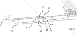
- the pawl 5 has a first leg 21 and a second leg 22, the legs 21, 22 - as in Fig. 4 marked - are arranged at an angle ⁇ to each other.
- the first leg 21 has a bevel 10 on its underside, the function of which will be explained later.
- a guide bolt 7 is connected to both side areas L, E of the tread plate 2.
- the guide bolts 7 therefore represent guide elements arranged on the tread plate side so as to be fixed in motion.
- a respective guide bolt 7 is located in one on the First and second extension rail 11, 12 arranged elongated hole 6 guided in a linearly movable manner.
- the elongated hole 6 therefore provides a guide device. As can be seen from the figures, the elongated hole 6 extends along a longitudinal section of the extension rail.
- the pawl 5 When executing a displacement movement of the tread plate arrangement 1 from the retracted towards the extended position (i.e. a displacement movement in the extension direction A, cf. Fig. 1 ), the pawl 5 assumes a position in which the guide pin 7 abuts a first end section 51 of the pawl ( Fig. 3 ). Since the drive unit 4 directly transmits the displacement movement to the tread plate 2, the tread plate 2 takes the extension rails 11, 12 with it through the guide pins 7 abutting on the respective locking pawls 5 when the extension-displacement movement is carried out.
- the guide pin 7 strikes a first elongated hole end 31 ( Fig. 3 ) and thus takes the extension rails 11, 12 (the extension unit 3) with it.
- the stop occurs with a second end section 52 of the pawl 5.
- the pawl 5 undergoes a pivoting movement, as a result of which the pawl 5 abuts with its first end section 51 on a second stop element 42 which is arranged on the vehicle side in a non-displaceable manner.
- This process enables a relative displacement of the respective guide bolts 7 in the elongated holes 6 of the respective extension rails 11, 12 (the Fig.
- the guide pin 7 can be moved longitudinally in the elongated hole 6). If, in the extended position of the tread plate arrangement 1, the extension unit 3 is locked by the pawl 5 with respect to a displacement movement along the displacement axis V and a displacement force is exerted on the tread plate 2 in the extension direction A via the drive unit 4, the tread plate 2 is opposite the extension unit 3 formed by the extension rails 11, 12 is displaced.
- the displacement path is limited by the length of the elongated holes 6, in particular by respective first and second elongated hole ends 31, 32.
- an edge of the first leg 21 of the pawl 5 facing the guide pin 7 has a bevel 10.
- the bevel 10 allows simplified sliding of the guide pin 7 during movement or displacement along the elongated hole 6.
- the bevel 10 is designed such that the first leg 21 is based on a cutting plane perpendicular to and along the displacement axis V, starting from the first leg end 21 (of the first leg) tapers in the direction of the connecting section 23 arranged between the first and second legs 21, 22.
- the tread plate 2 when the tread plate 2 is moved in the extension direction A relative to the extension rails 11, 12, the tread plate 2 also experiences an inclination, namely in the sense of pivoting away.
- the guide bolts 7 mounted in the elongated holes 6 rotate by the amount of inclination.
- the tread plate 2 is connected to the first and second extension rails 11, 12 via a joint arrangement 9.
- the respective joint arrangements 9 include two identical joint elements 13, which on the one hand are on the side areas L, R (see Fig. 2 ) of the tread plate 2 (i.e. in those areas of the tread plate 2 facing the extension rails 11, 12) and on the other hand on a front end section 14 of the respective extension rails 11, 12 facing the outside of the vehicle.
- the joint elements 13 mediate the tilting movement.
- the joint elements 13 are moved from a position parallel to the extension rails 11, 12 ( Fig. 1 , 3 ) also reluctant ( Fig. 2 , 6 ).
- the joint elements 13 can have an elongated hole 15, in which an engagement element 17 arranged in the end region 16 of the extension rails 11, 12 engages.
- the elongated hole 15 can be displaced relative to the engagement element 17, that is, the elongated hole 15 is moved relative to the position-fixed engagement element 17.
- Such an articulation of the tread plate 2 on the extension unit 3 acts in the manner of a crank mechanism when the tread plate 2 is lowered.
- bearing recesses 18 can be formed in the extension rails 11, 12, in which a bearing roller (not shown) arranged on the respective joint elements 13 is mounted in a non-inclined position of the tread plate 2.
- the bearing roller is arranged at that end 19 of the joint element 13, which is opposite an end 20 of the joint element 13 that is articulated to the tread plate 2.
- the joint elements 13 are arranged parallel to the extension rails 11, 12, which is why the bearing roller mentioned is mounted in the bearing recess 18 in such a position.
- the bearing recess 18 is preferably designed in the manner of a half-shell, so that the bearing roller can be easily extended from the bearing recess 18 when the tread plate 2 is lowered.
Description
Die vorliegende Erfindung betrifft eine Zustiegeinrichtung für ein Fahrzeug, insbesondere für ein Schienenfahrzeug, umfassend eine linearverschiebbar angeordnete Trittplattenanordnung, die gebildet ist aus einer Trittplatte und einer mit der Trittplatte wirkverbundenen Ausschubeinheit, sowie eine Antriebseinheit, die dazu eingerichtet ist, die aus der Trittplatte und der Ausschubeinheit gebildete Trittplattenanordnung entlang einer Verschiebeachse unter Ausführung einer Verschiebebewegung von einer eingefahrenen Stellung hin zu einer ausgefahrenen Stellung zu verschieben und umgekehrt.The present invention relates to an boarding device for a vehicle, in particular for a rail vehicle, comprising a linearly displaceable tread plate arrangement, which is formed from a tread plate and an extension unit operatively connected to the tread plate, and a drive unit which is set up to consist of the tread plate and the To move the tread plate arrangement formed by the push-out unit along a displacement axis while executing a displacement movement from a retracted position to an extended position and vice versa.
Bei Fahrzeugen unterschiedlicher Art, insbesondere jedoch bei Fahrzeugen des öffentlichen Personentransports, wird auf Zustiegeinrichtungen der eingangs beschriebenen oder ähnlicher Bauart zurückgegriffen. Unter einem "Fahrzeug" kann vorliegend insbesondere ein radgebundenes oder ein schienengebundenes Fahrzeug zu verstehen sein. Bei radgebundenen Fahrzeugen kann es sich im vorliegenden Kontext insbesondere um Transportfahrzeuge für den Personenverkehr handeln, beispielsweise um Busfahrzeuge. Bei schienengebundenen Fahrzeugen kann es sich im vorliegenden Sachzusammenhang ebenfalls um Transportfahrzeuge für den Personenverkehr handeln, beispielsweise um Straßenbahnen, S-Bahnen, Züge (Regionalzüge, Fernzüge), U-Bahnen, Trams, etc. Grundsätzlich können Zustiegeinrichtungen jedoch bei Fahrzeugen jeglicher Art eingesetzt werden, bei welchen beim Ein- oder Ausstieg von Personen ein Höhenunterschied oder ein Spalt zwischen einem Haltesteig und einer Trittfläche im Innenraum des Fahrzeugs überwunden werden muss. Eine solche Situation kann beispielsweise auch beim Halten eines Flugzeugs an einem Gate bzw. Haltesteig des Gates auftreten, weshalb auch bei Flugzeugen Zustiegeinrichtungen zum Einsatz kommen können.For vehicles of different types, but especially for public transport vehicles, access devices of the type described above or of a similar type are used. In the present case, a “vehicle” can be understood to mean, in particular, a wheeled or rail-bound vehicle. In the present context, wheeled vehicles can in particular be transport vehicles for passenger transport, for example bus vehicles. In this context, rail-bound vehicles can also be transport vehicles for passenger transport, for example trams, S-Bahn trains, trains (regional trains, long-distance trains), subways, trams, etc. In principle, however, boarding facilities can be used for vehicles of any kind , in which a difference in height or a gap between a handrail and a step in the interior of the vehicle must be overcome when people get in or out. Such a situation can also occur, for example, when an aircraft stops at a gate or the gate's holding platform, which is why boarding facilities can also be used on aircraft.
Entsprechend dienen Zustiegeinrichtungen der Erleichterung des Ein- und Ausstiegs in ein Fahrzeug vorbeschriebener Art. Aus dem Stand der Technik, beispielsweise der
Schiebetritteinrichtungen beruhen darauf, dass eine Trittplatte zwischen einer eingefahrenen und einer ausgefahrenen Stellung hin- und herbewegt wird, insbesondere entlang einer sich in Fahrzeugquerrichtung erstreckenden Verschiebeachse. In der ausgefahrenen Stellung stellt die Trittplatte eine Trittfläche bereit, über welche eine Person das Fahrzeug betreten oder aus diesem aussteigen kann. Um eine solche Linearverschiebung der Trittplatte zu gewährleisten, kann die Trittplatte mittels einer Führung in einem fahrzeugseitigen Gehäuse oder einem Rahmen linearverschiebbar geführt sein. Schiebetritte erleichtern das Ein- und Aussteigen aus einem Fahrzeug, indem sie einen zwischen dem Fahrzeug und einem Haltesteig (z.B. einer Bahnsteigkante) vorliegenden Spalt überbrücken. Klapptritte (insbesondere rampenartig ausgebildete Klapptritte) sind insbesondere dazu vorgesehen, Höhenunterschiede zwischen einem Fahrzeuginneren (z.B. einem dort vorgesehenen Fußboden) und einem Haltesteig zu überwinden, können aber auch zur Überbrückung eines Spalts zwischen Fahrzeug und Haltesteig eingesetzt werden.Sliding step devices are based on the fact that a step plate is moved back and forth between a retracted and an extended position, in particular along a displacement axis extending in the transverse direction of the vehicle. In the extended position, the tread plate provides a tread surface through which a person can enter or exit the vehicle. In order to ensure such a linear displacement of the tread plate, the tread plate can be guided in a linearly displaceable manner by means of a guide in a vehicle-side housing or a frame. Sliding steps make it easier to get in and out of a vehicle by bridging a gap between the vehicle and a platform (e.g. a platform edge). Folding steps (in particular folding steps designed like a ramp) are intended in particular to overcome differences in height between a vehicle interior (e.g. a floor provided there) and a parking platform, but can also be used to bridge a gap between the vehicle and the parking platform.
Problematisch ist häufig, dass der Abstand zwischen Fahrzeug und Haltesteig nicht konstant ist, sondern je nach den baulichen Gegebenheiten des Haltesteigs, bzw. dem einer konkret vorliegenden Haltesituation variiert. Gleiches kann für eine Höhendifferenz zwischen Fahrzeug und Haltesteig gelten, sodass nebst einem möglicherweise vorliegenden Spalt auch eine bestimmte Höhendifferenz von einer ein- oder aussteigenden Person überwunden werden muss. Je nach vorliegender Höhendifferenz, kann ein Schiebetritt zwar einen zwischen dem Haltesteig und dem Fahrzeug vorliegenden Spalt überbrücken, jedoch nicht eine vorliegende Höhendifferenz ausgleichen. Entsprechend kann bei Vorsehen eines alleinigen Schiebetritts ein barrierefreier Zustieg nicht in sämtlichen Haltesituationen bzw. an sämtlichen Haltesteigen sichergestellt werden.It is often problematic that the distance between the vehicle and the stop is not constant, but varies depending on the structural conditions of the stop or the specific stopping situation. The same can apply to a difference in height between the vehicle and the sidewalk, so that in addition to a possible gap, a certain height difference must also be overcome by a person getting in or out. Depending on the existing height difference, a sliding step can bridge a gap between the platform and the vehicle, but cannot compensate for an existing height difference. Accordingly, barrier-free boarding cannot be ensured in all stopping situations or on all stopping platforms if only a sliding step is provided.
Entsprechend liegt der vorliegenden Erfindung die Aufgabe zugrunde, eine Zustiegeinrichtung bereitzustellen, mit welcher ein sicherer Personenzustieg bei unterschiedlichen Höhenniveaus und/oder Abständen zwischen einem Fahrzeug und einem Haltesteig gewährleistet ist, und mit welcher sich unterschiedliche Höhenniveaus und/oder Abstände flexibel überbrücken lassen.Accordingly, the present invention is based on the object of providing an boarding device with which safe boarding of people is ensured at different height levels and / or distances between a vehicle and a holding platform, and with which different height levels and / or distances can be flexibly bridged.
Zur Lösung dieser Aufgabe wird eine Zustiegeinrichtung mit den Merkmalen des Anspruchs 1 vorgeschlagen.To solve this problem, an boarding device with the features of
Es ist darauf hinzuweisen, dass die in den Ansprüchen einzeln aufgeführten Merkmale in beliebiger, technisch sinnvoller Weise miteinander kombiniert werden können und weitere Ausgestaltungen der Erfindung aufzeigen. Die Beschreibung charakterisiert und spezifiziert die Erfindung insbesondere im Zusammenhang mit den Figuren zusätzlich.It should be noted that the features listed individually in the claims can be combined with one another in any technically sensible manner and show further refinements of the invention. The description additionally characterizes and specifies the invention, particularly in connection with the figures.
Es sei ferner darauf hingewiesen, dass eine hierin verwendete, zwischen zwei Merkmalen stehende und diese miteinander verknüpfende Konjunktion "und/oder" stets so auszulegen ist, dass in einer ersten Ausgestaltung des erfindungsgemäßen Gegenstands lediglich das erste Merkmal vorhanden sein kann, in einer zweiten Ausgestaltung lediglich das zweite Merkmal vorhanden sein kann und in einer dritten Ausgestaltung sowohl das erste als auch das zweite Merkmal vorhanden sein können.It should also be noted that a conjunction "and/or" used here between two features and linking them together must always be interpreted in such a way that in a first embodiment of the subject matter according to the invention only the first feature can be present, in a second embodiment only the second feature can be present and in a third embodiment both the first and the second feature can be present.
Wie erwähnt, betrifft die vorliegende Erfindung eine Zustiegeinrichtung für ein Fahrzeug, insbesondere für ein Schienenfahrzeug, umfassend eine linearverschiebbar angeordnete Trittplattenanordnung, die gebildet ist aus einer Trittplatte und einer mit der Trittplatte wirkverbundenen Ausschubeinheit, wobei die Ausschubeinheit eine erste und eine zweite Ausschubschiene aufweist, wobei die erste und zweite Ausschubschiene parallel zueinander angeordnet sind, und wobei die Trittplatte zwischen der ersten und zweiten Ausschubschiene angeordnet ist, sowie eine Antriebseinheit, die dazu eingerichtet ist, die aus der Trittplatte und der Ausschubeinheit gebildete Trittplattenanordnung entlang einer Verschiebeachse unter Ausführung einer Verschiebebewegung von einer eingefahrenen Stellung hin zu einer ausgefahrenen Stellung zu verschieben und umgekehrt. Die erfindungsgemäße Zustiegeinrichtung zeichnet sich aus durch zumindest ein Sperrmittel, das dazu eingerichtet ist, in der ausgefahrenen Stellung der Trittplattenanordnung ein Verschieben der Ausschubeinheit entlang der Verschiebeachse zu blockieren, und zugleich eine Relativbewegung zwischen der Trittplatte und der Ausschubeinheit freizugeben, in Folge dessen die Trittplatte relativ zur Ausschubeinheit verschieb- und neigbar ist.As mentioned, the present invention relates to an boarding device for a vehicle, in particular for a rail vehicle, comprising a linearly displaceable tread plate arrangement which is formed from a tread plate and an extension unit operatively connected to the tread plate, the extension unit having a first and a second extension rail, wherein the first and second extension rails are arranged parallel to one another, and wherein the tread plate is arranged between the first and second extension rails, and a drive unit which is designed to move the tread plate arrangement formed from the tread plate and the extension unit along a displacement axis, executing a displacement movement of one from a retracted position to an extended position and vice versa. The access device according to the invention is characterized by at least one locking means which is designed to block displacement of the extension unit along the displacement axis in the extended position of the tread plate arrangement, and at the same time to release a relative movement between the tread plate and the extension unit, as a result of which the tread plate is relatively can be moved and tilted to the extension unit.
Wesentlich für die vorliegende Erfindung ist, dass die Zustiegeinrichtung nebst der aus dem Stand der Technik wohlbekannten Schiebetrittfunktion auch eine Rampenfunktion bereitstellt, d.h. eine zwischen einem Fahrzeug und einem Haltesteig vorliegende Höhendifferenz kann durch die Zustiegeinrichtung überwunden werden, sodass auch im Falle eines unterhalb eines Fahrzeug-Fußbodenniveaus liegenden Haltesteig-Höhenniveaus ein sicherer und barrierefreier Ein- und Ausstieg in das Fahrzeug ermöglicht ist. Mit der vorliegenden Erfindung wird also eine Zustiegeinrichtung bereitgestellt, die nebst einer klassischen Schiebetrittfunktion auch eine Rampenfunktion bereitstellt.It is essential for the present invention that the boarding device, in addition to the sliding step function well known from the prior art, also provides a ramp function, ie one between a vehicle and a vehicle The height difference present on the parking platform can be overcome by the boarding device, so that safe and barrier-free entry and exit into the vehicle is possible even in the event of a parking platform height level below the vehicle floor level. The present invention therefore provides an boarding device which, in addition to a classic sliding step function, also provides a ramp function.
Unter einer "Zustiegeinrichtung" ist im Sinne der Erfindung eine Einrichtung zu verstehen, vermöge dessen einer Person der Ein- oder Ausstieg in ein Fahrzeug erleichtert bzw. ermöglicht wird. Die Trittplatte wird beim Ein- oder Ausstieg gewichtsbelastet, beispielsweise durch die Trittbelastung einer zusteigenden Person.For the purposes of the invention, an “boarding device” is to be understood as a device which makes it easier or possible for a person to get in or out of a vehicle. The tread plate is subjected to weight when entering or exiting, for example due to the impact of a person climbing on.
Unter einem "Fahrzeug" kann - wie eingangs erwähnt - insbesondere ein radgebundenes oder schienengebundenes Fahrzeug zu verstehen sein. Bei radgebundenen Fahrzeugen kann es sich insbesondere um Transportfahrzeuge für den Personenverkehr handeln, beispielsweise um Busfahrzeuge. Bei schienengebundenen Fahrzeugen kann es sich ebenfalls um Transportfahrzeuge für den Personenverkehr handeln, beispielsweise um Straßenbahnen, S-Bahnen, Züge (Regionalzüge, Fernzüge), U-Bahnen, Trams, etc.As mentioned at the beginning, a “vehicle” can be understood to mean in particular a wheeled or rail-bound vehicle. Wheeled vehicles can in particular be transport vehicles for passenger transport, for example bus vehicles. Rail-bound vehicles can also be transport vehicles for passenger transport, for example trams, S-Bahn trains, trains (regional trains, long-distance trains), subways, trams, etc.
Bei der linearverschiebbar angeordneten Trittplattenanordnung handelt es sich um eine Anordnung von miteinander wirkverbundenen Komponenten, nämlich der Trittplatte und der Ausschubeinheit. Unter einer Wirkverbindung ist vorliegend zu verstehen, dass die der Trittplattenanordnung zugehörigen Komponenten, also die Trittplatte und die Ausschubeinheit, derart miteinander gekoppelt sind, dass beide Komponenten bei Ausführung einer Verschiebebewegung simultan verschiebbar sind. Dabei kann die Trittplatte die Ausschubeinheit mitnehmen oder umgekehrt. Entsprechend ist die Antriebseinheit mit der Trittplatte oder der Ausschubeinheit verbunden, sodass durch die Wirkverbindung beider Komponenten eine (zumindest mittelbare) Bewegungsübertragung auf beide Komponenten erfolgen kann, auch wenn die Antriebseinheit unmittelbar mit nur einer der Komponenten (z.B. der Trittplatte) verbunden ist. Die Wirkverbindung kann beispielsweise durch ein mechanisches Wirkverbindungsmittel oder einen Wirkverbindungsmechanismus bereitgestellt werden.The linearly displaceable tread plate arrangement is an arrangement of components that are operatively connected to one another, namely the tread plate and the extension unit. In the present case, an active connection is to be understood as meaning that the components belonging to the tread plate arrangement, i.e. the tread plate and the extension unit, are coupled to one another in such a way that both components can be displaced simultaneously when a displacement movement is carried out. The tread plate can take the extension unit with it or vice versa. Accordingly, the drive unit is connected to the treadle plate or the extension unit, so that through the operative connection of both components, a (at least indirect) transmission of movement to both components can take place, even if the drive unit is directly connected to only one of the components (e.g. the treadle plate). The active connection can be provided, for example, by a mechanical active connection means or an active connection mechanism.
Die Ausschubeinheit ist über eine geeignete Führung, beispielsweise eine Rollen- oder Schienenführung, in einer fahrzeugseitig vorgesehenen Führungsvorrichtung linearverschiebbar geführt. Auch die Trittplatte kann, beispielsweise unterseitig, über eine Führung, beispielsweise eine Rollen- oder Schienenführung, in einer fahrzeugseitig vorgesehenen Führungsvorrichtung linearverschiebbar geführt oder angeordnet sein. Die genannte Antriebseinheit ist vorzugsweise unmittelbar mit der Trittplatte oder einem daran befestigten Bauteil, beispielsweise einem Trittplattenträger verbunden. Aufgrund der zwischen Trittplatte und Ausschubeinheit bereitgestellten Wirkverbindung kann die Ausschubeinheit bei Linearverschiebung der Trittplatte entlang der Verschiebeachse mitgenommen werden, d.h. die Antriebseinheit kann eine Linearverschiebung der Trittplatte und der Ausschubeinheit entlang der Verschiebeachse, d.h. in Richtung der ausgefahrenen Stellung oder in Richtung der eingefahrenen Stellung bewirken. Zwischen Antriebseinheit und Trittplattenanordnung kann ein mechanisches Übertragungsmittel (z.B. ein Gestänge oder ein Antriebsriemen) vorgesehen sein, welches mit der Trittplatte, einem damit verbundenen Bauteil (z.B. einem Trittplattenträger) oder der Ausschubeinheit gekoppelt ist. Bei der Antriebseinheit kann es sich insbesondere um einen elektromotorischen Antrieb handeln. Die Verschiebung der Trittplatte und der Ausschubeinheit bei Ausführung der Verschiebebewegung der Trittplattenanordnung erfolgt gleichgerichtet und simultan. Die Verschiebung der Ausschubeinheit und Trittplatte erfolgt zudem in gleicher Geschwindigkeit.The extension unit is guided in a linearly displaceable manner in a guide device provided on the vehicle via a suitable guide, for example a roller or rail guide. The tread plate can also be guided or arranged in a linearly displaceable manner, for example on the underside, via a guide, for example a roller or rail guide, in a guide device provided on the vehicle. The drive unit mentioned is preferably connected directly to the tread plate or a component attached to it, for example a tread plate carrier. Due to the active connection provided between the tread plate and the extension unit, the extension unit can be carried along the displacement axis when the tread plate is linearly displaced, i.e. the drive unit can cause a linear displacement of the tread plate and the extension unit along the displacement axis, i.e. in the direction of the extended position or in the direction of the retracted position. A mechanical transmission means (e.g. a linkage or a drive belt) can be provided between the drive unit and the tread plate arrangement, which is coupled to the tread plate, a component connected thereto (e.g. a tread plate carrier) or the extension unit. The drive unit can in particular be an electric motor drive. The displacement of the tread plate and the extension unit when executing the displacement movement of the tread plate arrangement takes place in the same direction and simultaneously. The extension unit and tread plate are also moved at the same speed.
Die Trittplatte ist derart ausgebildet, dass sie beim Ein- oder Aussteigen mit dem Gewicht von einer oder mehreren Personen belastet werden kann. Dazu ist nicht zwingend erforderlich, dass die Trittplatte vollständig ausgefahren ist, denn auch in einer zwischen der eingefahrenen Stellung und der ausgefahrenen Stellung der liegenden Stellung der Trittplatte kann diese zum Einstieg verwendet, d.h. trittbelastet, werden. Je nach Abstand des Fahrzeugs (und damit der Zustiegeinrichtung) von einem Haltesteig, kann ein vollständiges Ausfahren der Trittplatte bis zur ausgefahrenen Stellung durch eine Haltesteigkante verhindert sein. In diesem Fall kann die Trittplatte auch in einer nicht vollständig ausgefahrenen Stellung trittbelastet werden. Ferner kann die Trittplatte anti-Rutsch Eigenschaften aufweisen, beispielsweise durch Ausbildung eines geeigneten Oberflächenprofils, einer geeigneten anti-Rutsch Beschichtung oder durch Verwendung einer anti-Rutsch Matte. Durch eine solche Ausgestaltung kann die Trittsicherheit einer in das Fahrzeug ein- oder aussteigenden Person weiter erhöht werden.The footplate is designed in such a way that it can bear the weight of one or more people when getting in or out. For this purpose, it is not absolutely necessary that the tread plate is fully extended, because even in a position between the retracted position and the extended position of the lying position of the tread plate, it can be used for entry, that is to say it can be stepped on. Depending on the distance of the vehicle (and thus the boarding facility) from a holding platform, a stopping platform edge may prevent the tread plate from being completely extended to the extended position. In this case, the tread plate can also be subjected to tread loads in a position that is not fully extended. Furthermore, the tread plate can have anti-slip properties, for example by forming a a suitable surface profile, a suitable anti-slip coating or by using an anti-slip mat. Such a design can further increase the sure-footedness of a person getting in or out of the vehicle.
Wie erwähnt, weist die Zustiegeinrichtung ferner zumindest ein Sperrmittel auf, das dazu eingerichtet ist, in der ausgefahrenen Stellung der Trittplattenanordnung ein Verschieben der Ausschubeinheit entlang der Verschiebeachse zu blockieren. Die Verschiebebewegung wird dabei sowohl in Richtung der eingefahrenen Stellung als auch in Richtung der ausgefahrenen Stellung blockiert. Bei Erreichen der ausgefahrenen Stellung kann ein Auslösemechanismus aktiviert werden, wodurch das zumindest eine Sperrmittel aktiviert und somit die Blockierung der Verschiebebewegung ausgelöst wird. Dabei nimmt das Sperrmittel eine Sperrstellung ein. Gleichsam kann das Sperrmittel durch einen Lösemechanismus gelöst und in eine Öffnungsstellung verbracht werden, in welcher eine Verschiebebewegung der Trittplattenanordnung in Richtung der eingefahrenen Stellung ermöglicht wird. Vorzugsweise sind zwei Sperrmittel vorgesehen.As mentioned, the access device also has at least one locking means which is designed to block displacement of the extension unit along the displacement axis in the extended position of the tread plate arrangement. The displacement movement is blocked both in the direction of the retracted position and in the direction of the extended position. When the extended position is reached, a trigger mechanism can be activated, whereby the at least one locking means is activated and thus the blocking of the displacement movement is triggered. The locking means assumes a locking position. At the same time, the locking means can be released by a release mechanism and brought into an open position, in which a displacement movement of the tread plate arrangement in the direction of the retracted position is made possible. Preferably two blocking means are provided.
Nebst der beschriebenen Blockier- bzw. Sperrfunktion gibt das zumindest eine Sperrmittel - in der ausgefahrenen Stellung der Trittplattenanordnung - eine Relativbewegung zwischen der Trittplatte und der Ausschubeinheit frei. In dieser Stellung ist die Trittplatte bewegungsbezogen von der Ausschubeinheit entkoppelt. Dadurch ist die Trittplatte relativ zur Ausschubeinheit verschieb- und neigbar. Während des Verschiebens der Trittplattenanordnung (also bei Ausführung der Verschiebebewegung) ist eine Relativbewegung zwischen Trittplatte und Ausschubeinheit hingegen verhindert, d.h. es erfolgt keine Relativverschiebung bzw. Neigung der Trittplatte relativ zur Ausschubeinheit. Bei der Relativbewegung kann es sich um eine überlagerte Verschiebe- und Neigungsbewegung handeln, d.h. die Relativbewegung der Trittplatte erfolgt nach Art einer Schwenkschiebebewegung mit Neigungs- und Linearverschiebungsanteilen. Beim Halten eines Fahrzeugs an einem Haltesteig muss die Trittplatte nicht zwingend um den maximal möglichen Neigungswinkel abgeneigt werden. Da die Trittplatte - je nach Höhenniveau des Haltesteigs - auf dem Haltesteig aufliegen kann, können Haltesituationen auftreten, in denen die Trittplatte nicht um den maximal möglichen Neigungswinkel relativ zur Ausschubeinheit geneigt ist, sondern lediglich um einen Teilneigungswinkel bezogen auf eine Maximalneigung. In einem solchen Fall wird der Neigungswinkel durch die relative Vertikalposition zwischen Fahrzeug und Haltesteig festgelegt.In addition to the blocking or locking function described, the at least one locking means - in the extended position of the tread plate arrangement - enables a relative movement between the tread plate and the extension unit. In this position, the tread plate is decoupled from the extension unit in terms of movement. This means that the tread plate can be moved and tilted relative to the extension unit. However, during the displacement of the tread plate arrangement (i.e. when executing the displacement movement), a relative movement between the tread plate and the extension unit is prevented, ie there is no relative displacement or inclination of the tread plate relative to the extension unit. The relative movement can be a superimposed displacement and inclination movement, ie the relative movement of the tread plate takes place in the manner of a pivoting-sliding movement with inclination and linear displacement components. When stopping a vehicle on a sidewalk, the tread plate does not necessarily have to be tilted to the maximum possible angle of inclination. Since the tread plate - depending on the height of the holding platform - can rest on the holding platform, stopping situations can occur in which the tread plate is not inclined by the maximum possible angle of inclination relative to the extension unit, but rather only by a partial inclination angle based on a maximum inclination. In such a case, the angle of inclination is determined by the relative vertical position between the vehicle and the pavement.
Die Ausschubeinheit weist eine erste und eine zweite Ausschubschiene auf, wobei die erste und zweite Ausschubschiene parallel zueinander angeordnet sind, und wobei die Trittplatte zwischen der ersten und zweiten Ausschubschiene angeordnet ist. Die erste und zweite Ausschubschiene erstrecken sich dabei entlang jeweiliger zur Verschiebeachse paralleler Ausschubschienenachsen. Bei Anordnung der Zustiegeinrichtung im Seitenbereich eines Fahrzeugs, also nicht in dessen Front- oder Heckbereich, erstrecken sich die erste und zweite Ausschubschiene somit in entlang einer Fahrzeugquerachse (sind also in Fahrzeugquerrichtung ausgerichtet). Die erste und zweite Ausschubschiene sind beabstandet (der Abstand wird durch die Trittplatte bereitgestellt) zueinander angeordnet und über eine geeignete Führung, beispielsweise eine Rollen- oder Schienenführung, in einer fahrzeugseitig vorgesehenen Führungsvorrichtung linearverschiebbar geführt. Die erste und zweite Ausschubschiene bilden erfindungsgemäß Ausschubeinheit und sind vorzugsweise aus Metall oder Kunststoff gefertigt. Bei Ausführung der Verschiebebewegung der Trittplattenanordnung erfahren die Ausschubschienen eine simultane und gleichgerichtete Verschiebebewegung.The extension unit has a first and a second extension rail, the first and second extension rails being arranged parallel to one another, and the tread plate being arranged between the first and second extension rails. The first and second extension rails extend along respective extension rail axes that are parallel to the displacement axis. When the boarding device is arranged in the side area of a vehicle, i.e. not in its front or rear area, the first and second extension rails thus extend along a transverse vehicle axis (i.e. are aligned in the transverse direction of the vehicle). The first and second extension rails are arranged at a distance from one another (the distance is provided by the tread plate) and are guided in a linearly displaceable manner via a suitable guide, for example a roller or rail guide, in a guide device provided on the vehicle. According to the invention, the first and second extension rails form an extension unit and are preferably made of metal or plastic. When executing the displacement movement of the tread plate arrangement, the extension rails experience a simultaneous and rectified displacement movement.
Weitere vorteilhafte Ausgestaltungen einer erfindungsgemäßen Zustiegeinrichtung ergeben sich aus den in den Unteransprüchen angegebenen sowie den nachfolgend beschriebenen Merkmalen. Auch die in den Unteransprüchen angegebenen Merkmale seien nachfolgend beschrieben.Further advantageous embodiments of an boarding device according to the invention result from the features specified in the subclaims and the features described below. The features specified in the subclaims are also described below.
Nach einer weiteren Ausgestaltung der Erfindung kann bei einer mit der Erfindung vorgeschlagenen Zustiegeinrichtung vorgesehen sein, dass das Sperrmittel eine Sperrklinke ist, die an einer der Ausschubschienen schwenkbar gelagert ist, insbesondere um eine sich in Fahrzeuglängsrichtung erstreckende Schwenkachse. Die Sperrklinke ist um eine sich in Fahrzeuglängsrichtung erstreckende Schwenkachse schwenkbar, sofern die Zustiegeinrichtung im Seitenbereich des Fahrzeugs angeordnet ist, also nicht im Front- oder Heckbereich positioniert ist. Grundsätzlich ist die Sperrklinke jedoch um eine sich senkrecht zur Verschiebeachse erstreckende Schwenkachse schwenkbar, unabhängig von der Anordnungsposition der Zustiegeinrichtung am Fahrzeug. Vorzugsweise ist sowohl an der ersten Ausschubschiene als auch an der zweiten Ausschubschiene eine Sperrklinke als Sperrmittel schwenkbar gelagert. In diesem Zusammenhang sei erwähnt, dass die erste und zweite Ausschubschiene vorzugsweise gleichartig ausgebildet sind, d.h. zum Beispiel die gleiche Länge, Breite, Tiefe etc. aufweisen. Bestimmte Funktionselemente, Aussparungen, Öffnungen, Führungseinrichtungen etc. sind daher vorzugsweise an beiden Ausschubschienen vorgesehen.According to a further embodiment of the invention, in an boarding device proposed by the invention it can be provided that the locking means is a locking pawl which is pivotally mounted on one of the extension rails, in particular about a pivot axis extending in the longitudinal direction of the vehicle. The pawl can be pivoted about a pivot axis extending in the longitudinal direction of the vehicle, provided that the access device is arranged in the side area of the vehicle, i.e. is not positioned in the front or rear area. In principle, however, the pawl can be pivoted about a pivot axis extending perpendicular to the displacement axis, regardless of the Arrangement position of the boarding facility on the vehicle. Preferably, a pawl is pivotally mounted as a locking means on both the first extension rail and the second extension rail. In this context, it should be mentioned that the first and second extension rails are preferably designed in the same way, that is, for example, have the same length, width, depth, etc. Certain functional elements, recesses, openings, guide devices, etc. are therefore preferably provided on both extension rails.
Nach einer weiteren Ausgestaltung der Erfindung kann bei einer mit der Erfindung vorgeschlagenen Zustiegeinrichtung vorgesehen sein, dass die Sperrklinke einen ersten Schenkel und einen zweiten Schenkel aufweist, wobei die Schenkel in einem Winkel zueinander angeordnet sind. Der Winkel kann zwischen 70° und 100°, insbesondere jedoch bei 90° liegen. Die Schwenklagerung der Sperrklinke ist dabei vorzugsweise in einem Verbindungsabschnitt des ersten und zweiten Schenkels verwirklicht. Beispielsweise kann die jeweilige Sperrklinke an einem an der jeweiligen Ausschubschiene angeordneten Lagerbolzen schwenkbar gelagert sein, so kann der genannte Lagerbolzen in eine im Verbindungsabschnitt der Sperrklinke vorgesehene Lochöffnung eingreifen. Die Sperrklinke (samt ihrer zwei Schenkel und dem Verbindungsabschnitt) sind vorzugsweise als Flachprodukt, beispielsweise als metallisches Flachprodukt, ausgebildet.According to a further embodiment of the invention, in an boarding device proposed by the invention it can be provided that the pawl has a first leg and a second leg, the legs being arranged at an angle to one another. The angle can be between 70° and 100°, but in particular 90°. The pivot bearing of the pawl is preferably implemented in a connecting section of the first and second legs. For example, the respective pawl can be pivotally mounted on a bearing pin arranged on the respective extension rail, so that said bearing pin can engage in a hole opening provided in the connecting section of the pawl. The pawl (including its two legs and the connecting section) are preferably designed as a flat product, for example as a metallic flat product.
Nach einer weiteren Ausgestaltung der Erfindung kann bei einer mit der Erfindung vorgeschlagenen Zustiegeinrichtung vorgesehen sein, dass die Trittplatte mit je einem trittplattenseitig bewegungsfest angeordneten Führungselement in einer an der ersten und zweiten Ausschubschiene ausgebildeten Führungseinrichtung linearbeweglich geführt ist. Vorzugsweise ist die genannte Führungseinrichtung also an beiden Ausschubschienen ausgebildet, dabei vorzugsweise auf gleicher Höhe und im gleichen Längsabschnitt. Die Führungselemente sind dabei jeweils in einem der jeweiligen Ausschubschiene zugewandten Abschnitt der Trittplatte angeordnet und bewegungsfest mit der Trittplatte oder einem damit verbundenen Bauteil verbunden. Das jeweilige Führungselement greift (zumindest teilweise) in die an der jeweiligen Ausschubschiene ausgebildete Führungseinrichtung ein. Im montierten Zustand sind die an den Ausschubschienen ausgebildeten Führungseinrichtungen gegenüberliegend angeordnet, gleichsam auch die Führungselemente.According to a further embodiment of the invention, it can be provided in an access device proposed by the invention that the tread plate is guided in a linearly movable manner with a guide element arranged on the tread plate side so that it cannot move in a linearly movable manner in a guide device formed on the first and second extension rail. Preferably, the guide device mentioned is formed on both extension rails, preferably at the same height and in the same longitudinal section. The guide elements are each arranged in a section of the tread plate facing the respective extension rail and are connected in a movement-resistant manner to the tread plate or a component connected to it. The respective guide element engages (at least partially) in the guide device formed on the respective extension rail. In the assembled state, the guide devices formed on the extension rails are arranged opposite each other, as are the guide elements.
Nach einer weiteren Ausgestaltung der Erfindung kann bei einer mit der Erfindung vorgeschlagenen Zustiegeinrichtung vorgesehen sein, dass die Führungseinrichtung ein sich entlang eines Ausschubschienen-Längsabschnitts erstreckendes Langloch ist, und dass das Führungselement ein Führungsbolzen ist. Entsprechend ist ein an einer der ersten Ausschubschiene zugewandten Trittplattenseite angeordneter Führungsbolzen in einem an der ersten Ausschubschiene ausgebildeten Langloch geführt bzw. greift zumindest teilweise in dieses ein. Ein an einer der zweiten Ausschubschiene zugewandten Trittplattenseite angeordneter Führungsbolzen ist in einem an der zweiten Ausschubschiene ausgebildeten Langloch geführt bzw. greift zumindest teilweise in dieses ein. Der Langlochdurchmesser kann an den Durchmesser des Führungsbolzens angepasst sein, sodass der Führungsbolzen innerhalb des Langlochs längsverschoben werden kann. Das jeweilige Langloch und/oder der jeweilige Führungsbolzen kann zur reibungsreduzierten Führung mit einem Schmiermittel geschmiert sein.According to a further embodiment of the invention, in an approach device proposed by the invention it can be provided that the guide device is an elongated hole extending along a longitudinal section of the extension rail, and that the guide element is a guide bolt. Accordingly, a guide pin arranged on a tread plate side facing the first extension rail is guided in an elongated hole formed on the first extension rail or engages at least partially in it. A guide pin arranged on a tread plate side facing the second extension rail is guided in an elongated hole formed on the second extension rail or engages at least partially in it. The elongated hole diameter can be adapted to the diameter of the guide pin, so that the guide pin can be moved longitudinally within the elongated hole. The respective elongated hole and/or the respective guide pin can be lubricated with a lubricant for friction-reduced guidance.
Nach einer weiteren Ausgestaltung der Erfindung kann bei einer mit der Erfindung vorgeschlagenen Zustiegeinrichtung vorgesehen sein, dass der Führungsbolzen ein Wirkverbindungsmittel zwischen der Trittplatte und der Ausschubeinheit ist. Entsprechend kann der Führungsbolzen eine Bewegungsübertragung zwischen Trittplatte und Ausschubeinheit vermitteln. Wird über die Antriebseinheit beispielsweise eine Verschiebebewegung in der Trittplatte veranlasst, so kann die Verschiebebewegung über den als Mitnehmer wirkenden Führungsbolzen auch auf die Ausschubeinheit (bzw. die Ausschubschienen) übertragen werden, sodass die Trittplatte und die Ausschubeinheit gleichzeitig eine Verschiebebewegung erfahren können.According to a further embodiment of the invention, in an access device proposed by the invention it can be provided that the guide pin is an operative connection means between the tread plate and the extension unit. Accordingly, the guide pin can transmit movement between the tread plate and the extension unit. If, for example, a displacement movement in the tread plate is initiated via the drive unit, the displacement movement can also be transmitted to the extension unit (or the extension rails) via the guide pin acting as a driver, so that the tread plate and the extension unit can undergo a displacement movement at the same time.
Nach einer weiteren Ausgestaltung der Erfindung kann bei einer mit der Erfindung vorgeschlagenen Zustiegeinrichtung vorgesehen sein, dass der Führungsbolzen dazu eingerichtet ist, bei Ausführung der Verschiebebewegung der Trittplattenanordnung von der eingefahrenen hin zur ausgefahrenen Stellung an einem ersten Endabschnitt der Sperrklinke anzuschlagen und somit die Ausschubeinheit mitzunehmen. Beim Ausfahren der Trittplattenanordnung (also bei Ausführung einer Verschiebebewegung von der eingefahrenen in Richtung der ausgefahrenen Stellung) kann sich die Sperrklinke in einer Stellung befinden, in welcher ein Anschlagen des Führungsbolzens an einem ersten Endabschnitt der Sperrklinke ermöglicht bzw. verwirklicht ist. Der erste Endabschnitt der Sperrklinke kann dabei vorzugsweise ein Schenkelende eines Schenkels der Sperrklinke sein. Bei Ausführung der Verschiebebewegung erfolgt vorzugsweise keine Relativverschiebung zwischen Führungsbolzen und dem Langloch, vielmehr sind beide Funktionselemente (bis auf geringfügige, z.B. vibrationsinduzierte Bewegungstoleranzen) statisch, d.h. positionsfest, zueinander angeordnet. Durch das Anschlagen des trittplattenseitig befestigten Führungsbolzens an der ausschubschienenseitig befestigten Sperrklinke kann eine durch die Antriebseinheit auf die Trittplatte übertragene Verschiebebewegung auf die Ausschubschiene übertragen werden. Entsprechend kann unter Einsatz der Antriebseinheit eine Verschiebebewegung der Ausschubschienen (also der Ausschubeinheit) erzeugt werden.According to a further embodiment of the invention, it can be provided in an access device proposed by the invention that the guide pin is set up to strike a first end section of the pawl when the sliding movement of the tread plate arrangement is carried out from the retracted to the extended position and thus to take the extension unit with it. When extending the tread plate arrangement (i.e. when executing a displacement movement from the retracted towards the extended position), the pawl can be in a position in which the guide bolt stops against a first end section of the Pawl enables or is realized. The first end section of the pawl can preferably be a leg end of a leg of the pawl. When executing the displacement movement, there is preferably no relative displacement between the guide pin and the elongated hole; rather, both functional elements (except for minor, eg vibration-induced movement tolerances) are arranged statically, ie in a fixed position, relative to one another. By striking the guide bolt attached to the tread plate side on the locking pawl attached to the extension rail side, a displacement movement transmitted to the tread plate by the drive unit can be transmitted to the extension rail. Accordingly, a displacement movement of the extension rails (i.e. the extension unit) can be generated using the drive unit.
Nach einer weiteren Ausgestaltung der Erfindung kann bei einer mit der Erfindung vorgeschlagenen Zustiegeinrichtung vorgesehen sein, dass der Führungsbolzen dazu eingerichtet ist, bei Ausführung der Verschiebebewegung der Trittplattenanordnung von der ausgefahrenen hin zur eingefahrenen Stellung an einem ersten Langlochende anzuschlagen und somit die Ausschubeinheit mitzunehmen. Bei Ausführung einer in Richtung der eingefahrenen Stellung gerichteten Verschiebebewegung schlägt der Führungsbolzen also nicht an der Sperrklinke an. Der als Mitnehmer agierende Führungsbolzen wirkt hierbei mit dem ersten Langlochende zusammen und überträgt an dieser Stelle die von der Antriebseinheit erzeugte und zunächst auf die Trittplatte übertragene Antriebskraft auch auf die jeweiligen Ausschubschienen der Ausschubeinheit, sodass diese unter Einsatz des Führungsbolzens mitgenommen werden können.According to a further embodiment of the invention, it can be provided in an access device proposed by the invention that the guide pin is set up to strike a first elongated hole end when the sliding movement of the tread plate arrangement is carried out from the extended to the retracted position and thus to take the extension unit with it. When a displacement movement is carried out in the direction of the retracted position, the guide pin does not strike the pawl. The guide pin, which acts as a driver, interacts with the first end of the elongated hole and at this point transmits the driving force generated by the drive unit and initially transmitted to the tread plate to the respective extension rails of the extension unit, so that these can be taken along using the guide pin.
Nach einer weiteren Ausgestaltung der Erfindung kann bei einer mit der Erfindung vorgeschlagenen Zustiegeinrichtung vorgesehen sein, dass die Sperrklinke in der ausgefahrenen Stellung der Trittplattenanordnung an ein erstes fahrzeugseitig verschiebefest angeordnetes Anschlagelement anschlägt und eine Schwenkbewegung erfährt, in Folge derer die Sperrklinke mit ihrem ersten Endabschnitt an ein zweites fahrzeugseitig verschiebefest angeordnetes Anschlagelement anschlägt. Der Anschlag an das erste Anschlagelement erfolgt dabei vorzugsweise mit einem im Bereich eines zweiten Endabschnitts der Sperrklinke angeordneten Schenkelende. Da die Sperrklinke mit der Ausschubeinheit unmittelbar verbunden ist, wird durch die beschriebene Anschlagstellung einerseits eine Verschiebung der Ausschubeinheit in Richtung der eingefahrenen Stellung (maßgebend ist hier der Anschlag des ersten Endabschnitts der Sperrklinke an dem zweiten fahrzeugseitig angeordneten Anschlagelement) und andererseits über die ausgefahrene Stellung hinaus (maßgebend ist hierbei der Anschlag des zweiten Endabschnitts der Sperrklinke an dem ersten fahrzeugseitig angeordneten Anschlagelement) verhindert. Durch jene in Folge des Anschlagens der Sperrklinke an dem ersten fahrzeugseitig verschiebefest angeordneten Anschlagelement wird die Sperrklinke in eine Stellung gebracht, die eine Bewegung des Führungsbolzens entlang des Langlochs ermöglicht. Wird über die mit der Trittplatte verbundene Antriebseinheit sodann eine weitere in Richtung der ausgefahrenen Stellung gerichtete Verschiebekraft auf die Trittplatte ausgeübt, so wird die Trittplatte relativ zu der Ausschubeinheit verschoben. Der Verschiebeweg entspricht einem Verschiebeweg des Führungsbolzens von dem ersten Langlochende bis zu einem zweiten, dem ersten Langlochende gegenüberliegenden, Langlochende. Die Länge des Langlochs legt also einen Verschiebebetrag zwischen Trittplatte und Ausschubeinheit in der ausgefahrenen Stellung der Ausschubeinheit fest. Betont sei, dass die Trittplatte bei Ausführung der Trittplattenverschiebung gegenüber der Ausschubeinheit nebst der Linearverschiebung auch eine Neigungsbewegung in Bezug zu einer von der Ausschubeinheit aufgespannten Ebene erfährt, insbesondere eine abwärts gerichtete Neigungsbewegung.According to a further embodiment of the invention, in an boarding device proposed by the invention, it can be provided that the pawl in the extended position of the tread plate arrangement abuts against a first stop element which is arranged on the vehicle side in a non-displaceable manner and undergoes a pivoting movement, as a result of which the pawl contacts with its first end section second stop element arranged on the vehicle side in a non-displaceable manner strikes. The stop on the first stop element is preferably carried out with a leg end arranged in the area of a second end section of the pawl. Since the pawl is directly connected to the extension unit, the described Stop position, on the one hand, a displacement of the extension unit in the direction of the retracted position (the decisive factor here is the stop of the first end section of the pawl on the second stop element arranged on the vehicle side) and, on the other hand, beyond the extended position (the decisive factor here is the stop of the second end section of the pawl on the first stop element arranged on the vehicle side). As a result of the pawl striking the first stop element arranged in a non-displaceable manner on the vehicle side, the pawl is brought into a position that enables the guide pin to move along the elongated hole. If a further displacement force directed in the direction of the extended position is then exerted on the tread plate via the drive unit connected to the tread plate, the tread plate is displaced relative to the extension unit. The displacement path corresponds to a displacement path of the guide bolt from the first elongated hole end to a second elongated hole end opposite the first elongated hole end. The length of the elongated hole therefore determines a displacement amount between the tread plate and the extension unit in the extended position of the extension unit. It should be emphasized that when the tread plate is shifted relative to the extension unit, in addition to the linear displacement, the tread plate also experiences an inclination movement in relation to a plane spanned by the extension unit, in particular a downward inclination movement.
Nach einer weiteren Ausgestaltung der Erfindung kann bei einer mit der Erfindung vorgeschlagenen Zustiegeinrichtung vorgesehen sein, dass der Führungsbolzen in einer maximal geneigten Stellung der Trittplatte an dem zweiten Langlochende anschlägt, wobei die Sperrklinke in dieser Stellung zugleich mit einem Lagerabschnitt an dem Führungsbolzen anliegt. Das Anschlagen des Führungsbolzens an dem zweiten Langlochende verhindert eine weitere Relativverschiebung bzw. Relativneigung der Trittplatte relativ zur - in dieser Stellung durch die Sperrklinke arretierten - Ausschubeinheit. Der Führungsbolzen stützt die Sperrklinke in dieser Stellung zusätzlich ab (durch das Anliegen der Sperrklinke an dem Führungsbolzen mit ihrem Lagerabschnitt). Vorteilhaft kann es sein, wenn eine dem Führungsbolzen zugewandte Kante des ersten Schenkels der Sperrklinke eine Anschrägung aufweist. Die Anschrägung erlaubt ein vereinfachtes Gleiten des Führungsbolzens bei der Bewegung entlang des Langlochs. Die Anschrägung ist vorzugsweise derart ausgebildet, dass sich der erste Schenkel bezogen auf eine senkrecht zur und entlang Verschiebeachse verlaufende Schnittebene ausgehend vom ersten Schenkelende (des ersten Schenkels) in Richtung des zwischen erstem und zweitem Schenkel angeordneten Verbindungsabschnitts verjüngt.According to a further embodiment of the invention, it can be provided in an approach device proposed by the invention that the guide pin abuts on the second elongated hole end in a maximally inclined position of the tread plate, the pawl in this position simultaneously resting on the guide pin with a bearing section. The striking of the guide pin on the second end of the elongated hole prevents further relative displacement or relative inclination of the tread plate relative to the extension unit - which is locked in this position by the pawl. The guide pin additionally supports the pawl in this position (by the pawl resting on the guide pin with its bearing section). It can be advantageous if an edge of the first leg of the pawl facing the guide pin has a bevel. The bevel allows the guide pin to slide more easily when moving along the slot. The bevel is preferably designed in such a way that the first leg tapers in relation to a cutting plane running perpendicular to and along the displacement axis, starting from the first leg end (of the first leg) in the direction of the connecting section arranged between the first and second leg.
Nach einer weiteren Ausgestaltung der Erfindung kann bei einer mit der Erfindung vorgeschlagenen Zustiegeinrichtung vorgesehen sein, dass der Führungsbolzen während der Relativbewegung zwischen der Trittplatte und Ausschubeinheit entlang des Langlochs verschoben wird. Beim Anschlagen der Sperrklinke an dem ersten fahrzeugseitigen Anschlagelement in der ausgefahrenen Stellung der Trittplattenanordnung liegt der Führungsbolzen an dem ersten Langlochende an. Sofern dann die Trittplatte relativ zur Ausschubeinheit in Ausfahrrichtung verschoben und relativ zur Ausschubeinheit abgeneigt wird, wird der mit der Trittplatte verbundene Führungsbolzen entlang des Langlochs verschoben. In der maximalen Verschiebe- bzw. Neigestellung zwischen Trittplatte und Ausschubeinheit liegt der Führungsbolzen an dem zweiten Langlochende ab.According to a further embodiment of the invention, in an approach device proposed by the invention it can be provided that the guide pin is displaced along the elongated hole during the relative movement between the tread plate and the extension unit. When the pawl strikes the first vehicle-side stop element in the extended position of the tread plate arrangement, the guide pin rests on the first elongated hole end. If the tread plate is then moved relative to the extension unit in the extension direction and tilted relative to the extension unit, the guide pin connected to the tread plate is displaced along the elongated hole. In the maximum displacement or tilting position between the tread plate and the extension unit, the guide pin rests on the second end of the slot.
Nach einer weiteren Ausgestaltung der Erfindung kann bei einer mit der Erfindung vorgeschlagenen Zustiegeinrichtung vorgesehen sein, dass die Trittplatte über den Führungsbolzen schwenkbar gegenüber der Ausschubeinheit gelagert ist, wobei ein Verschwenken zwischen Trittplatte und Ausschubeinheit ausschließlich in der ausgefahrenen Stellung der Ausschubeinheit (d.h. der Ausschubschienen) ermöglicht ist. Insbesondere ist die Trittplatte über zwei im Seitenbereich der Trittplatte (also den jeweiligen Ausschubschienen zugewandten Seitenbereichen der Trittplatte) angeordnete Führungsbolzen schwenkbar gegenüber der Ausschubeinheit gelagert. Durch das Anschlagen des jeweiligen Führungsbolzens an dem jeweiligen zweiten Langlochende des jeweiligen Langlochs sowie durch die Arretierung der Ausschubeinheit durch die Sperrklinke(n), ist der jeweilige Führungsbolzen in der ausgefahrenen Stellung der Ausschubeinheit in seiner Längsposition festgelegt. Die Positionsfestlegung ermöglicht ein sicheres Verschwenken der Trittplatte gegenüber der Ausschubeinheit. In der genannten Stellung kann der jeweilige Führungsbolzen also innerhalb des Langlochs eine Rotationsbewegung erfahren. Die Rotationsbewegung entspricht der Neigebewegung der Trittplatte. Die jeweiligen Langlöcher stellen also nicht nur Längsführungen für die Führungsbolzen bereit, sondern auch entsprechende Schwenklager. Dadurch dass die Führungsbolzen - nebst der vorangehend beschriebenen Funktionen - auch eine Schwenklagerung für die Trittplatte bereitstellen können, kann auf das Vorsehen einer zusätzlichen Schwenklagereinrichtung verzichtet werden, die Gesamtkonstruktion kann also kompakter und mit weniger Materialeinsatz konstruiert werden.According to a further embodiment of the invention, it can be provided in an access device proposed by the invention that the tread plate is pivotally mounted relative to the extension unit via the guide pin, with pivoting between the tread plate and extension unit only being possible in the extended position of the extension unit (ie the extension rails). is. In particular, the tread plate is pivotably mounted relative to the extension unit via two guide bolts arranged in the side region of the tread plate (i.e. the side regions of the tread plate facing the respective extension rails). By striking the respective guide pin on the respective second elongated hole end of the respective elongated hole and by locking the extension unit by the pawl(s), the respective guide pin is fixed in its longitudinal position in the extended position of the extension unit. Determining the position enables the tread plate to be pivoted safely relative to the extension unit. In the position mentioned, the respective guide pin can therefore experience a rotational movement within the elongated hole. The rotation movement corresponds to the tilting movement of the tread plate. The respective elongated holes not only provide longitudinal guides for the guide bolts, but also corresponding pivot bearings. Because the guide bolts - in addition to the previous one Functions described - can also provide a pivot bearing for the tread plate, the provision of an additional pivot bearing device can be dispensed with, so the overall construction can be constructed more compactly and with less use of material.
Nach einer weiteren Ausgestaltung der Erfindung kann bei einer mit der Erfindung vorgeschlagenen Zustiegeinrichtung vorgesehen sein, dass die Trittplatte jeweils über eine Gelenkanordnung mit der ersten und zweiten Ausschubschiene verbunden ist. Die Gelenkanordnung betrifft insbesondere zwei baugleich ausgebildete Gelenkelemente, die nach Art eines länglichen oder stabförmigen Flachprodukts ausgebildet sind, und die einerseits an den Seitenbereichen der Trittplatte (also in jenen der Ausschubschienen zugewandten Bereichen der Trittplatte) und andererseits an einem vorderen, nach fahrzeugaußen gewandten, Endabschnitt der jeweiligen Ausschubschienen angelenkt sind. Beim Neigen der Trittplatte relativ zur Ausschubeinheit vermitteln die Gelenkelemente bzw. Riegel die Neigungsbewegung. Beim Abneigen der Trittplatte relativ zur Ausschubeinheit werden die Gelenkelemente ausgehend von einer zu den Ausschubschienen parallelen Stellung ebenfalls abgeneigt. Die Gelenkelemente können ein Langloch aufweisen, in welchem jeweils ein im Endbereich der Ausschubschienen angeordnetes Eingriffselement eingreift. Beim Neigen der Trittplatte relativ zur Ausschubeinheit kann das Langloch entlang des Eingriffselements gleiten. Eine solche Anlenkung der Trittplatte an der Ausschubeinheit kann nach Art eines Kurbeltriebs ausgebildet sein.According to a further embodiment of the invention, in an boarding device proposed by the invention it can be provided that the tread plate is connected to the first and second extension rails via a joint arrangement. The joint arrangement relates in particular to two joint elements of identical construction, which are designed in the manner of an elongated or rod-shaped flat product, and which are on the one hand on the side regions of the tread plate (i.e. in those areas of the tread plate facing the extension rails) and on the other hand on a front end section facing towards the outside of the vehicle the respective extension rails are articulated. When tilting the tread plate relative to the extension unit, the joint elements or latches mediate the tilting movement. When tilting the tread plate relative to the extension unit, the joint elements are also tilted starting from a position parallel to the extension rails. The joint elements can have an elongated hole, in which an engagement element arranged in the end region of the extension rails engages. When tilting the tread plate relative to the extension unit, the elongated hole can slide along the engagement element. Such an articulation of the tread plate on the extension unit can be designed in the manner of a crank mechanism.
Nach einer weiteren Ausgestaltung der Erfindung kann bei einer mit der Erfindung vorgeschlagenen Zustiegeinrichtung vorgesehen sein, dass die Relativbewegung zwischen der Trittplatte und der Ausschubeinheit eine überlagerte Schwenk-Schiebebewegung ist, bei welcher die Trittplatte relativ zur Ausschubeinheit entlang der Verschiebeachse über einen einer Länge des Langlochs entsprechenden Betrag verschiebbar ist, und bei welcher die Trittplatte relativ zur Ausschubeinheit maximal um einen von den Gelenkanordnungen festgelegten maximalen Neigungswinkel neigbar ist.According to a further embodiment of the invention, it can be provided in an access device proposed by the invention that the relative movement between the tread plate and the extension unit is a superimposed pivoting-sliding movement, in which the tread plate is relative to the extension unit along the displacement axis over a length corresponding to the length of the elongated hole Amount can be moved, and in which the tread plate can be tilted relative to the extension unit by a maximum angle of inclination determined by the joint arrangements.
Weitere Merkmale und Vorteile der Erfindung ergeben sich aus der folgenden Beschreibung nicht einschränkend zu verstehender Ausführungsbeispiele derFurther features and advantages of the invention result from the following description of exemplary embodiments which are not to be understood as restrictive
Erfindung, welche im Folgenden unter Bezugnahme auf die Zeichnungen näher erläutert werden. In dieser Zeichnung zeigen schematisch:
- Fig. 1
- eine perspektivische Ansicht eines ersten Ausführungsbeispiels einer erfindungsgemäßen Zustiegeinrichtung, wobei sich die zugehörige Trittplattenanordnung in einer teilweise ausgefahrenen Stellung befindet;
- Fig. 2
- eine perspektivische Ansicht einer erfindungsgemäßen Zustiegeinrichtung nach dem ersten Ausführungsbeispiel, wobei sich die Ausschubeinheit in einer ausgefahrenen Stellung befindet und die Trittplatte relativ zur Ausschubeinheit abgeneigt ist;
- Fig. 3
- eine vergrößerte Ansicht eines Ausschnitts einer erfindungsgemäßen Zustiegeinrichtung nach dem ersten Ausführungsbeispiel im Bereich einer Ausschubschiene, wobei sich die Trittplattenanordnung in einer eingefahrenen Stellung befindet;
- Fig. 4
- eine vergrößerte Ansicht eines Ausschnitts einer Zustiegeinrichtung in einer Stellung der Trittplattenanordnung nach
Fig. 3 , - Fig. 5
- eine vergrößerte Ansicht eines Ausschnitts einer erfindungsgemäßen Zustiegeinrichtung nach dem ersten Ausführungsbeispiel im Bereich einer Ausschubschiene, wobei sich die Ausschubeinheit in einer ausgefahrenen Stellung befindet und die Trittplatte relativ zur Ausschubeinheit abgeneigt ist;
- Fig. 6
- eine perspektivische Ansicht eines Ausschnitts einer erfindungsgemäßen Zustiegeinrichtung nach einem zweiten Ausführungsbeispiel der Erfindung, wobei sich die Ausschubeinheit in einer ausgefahrenen Stellung befindet und die Trittplatte relativ zur Ausschubeinheit abgeneigt ist.
- Fig. 1
- a perspective view of a first exemplary embodiment of an boarding device according to the invention, with the associated tread plate arrangement being in a partially extended position;
- Fig. 2
- a perspective view of an boarding device according to the invention according to the first exemplary embodiment, wherein the extension unit is in an extended position and the tread plate is inclined relative to the extension unit;
- Fig. 3
- an enlarged view of a section of an boarding device according to the invention according to the first exemplary embodiment in the area of an extension rail, with the tread plate arrangement being in a retracted position;
- Fig. 4
- an enlarged view of a section of an access device in a position of the tread plate arrangement
Fig. 3 , - Fig. 5
- an enlarged view of a section of an access device according to the invention according to the first exemplary embodiment in the area of an extension rail, the extension unit being in an extended position and the tread plate being inclined relative to the extension unit;
- Fig. 6
- a perspective view of a section of an access device according to the invention according to a second exemplary embodiment of the invention, wherein the extension unit is in an extended position and the tread plate is inclined relative to the extension unit.
In der
Die Zustiegeinrichtung umfasst eine linearverschiebbar angeordnete Trittplattenanordnung 1, welche sich zusammensetzt aus einer Trittplatte 2 und einer mit der Trittplatte 2 wirkverbundenen Ausschubeinheit 3. Beim Ein- oder Aussteigen einer Person wird die Trittplatte 2 trittbelastet, d.h. mit der Gewichtskraft der Person beaufschlagt. Über eine Antriebseinheit 4 ist die aus der Trittplatte 2 und der Ausschubeinheit 3 gebildete Trittplattenanordnung 1 entlang einer Verschiebeachse V unter Ausführung einer Verschiebebewegung von einer eingefahrenen Stellung hin zu einer ausgefahrenen Stellung verschiebbar und umgekehrt. In der
In sämtlichen Figuren ist erkennbar, dass die Ausschubeinheit 3 aus einer ersten Ausschubschiene 11 und einer zweiten Ausschubschiene 12 gebildet ist (siehe z.B.
Die Zustiegeinrichtung umfasst ein Sperrmittel, das dazu eingerichtet ist, in der ausgefahrenen Stellung der Trittplattenanordnung 1 ein Verschieben der Ausschubeinheit 3 entlang der Verschiebeachse V zu blockieren, dies gilt sowohl für ein Verschieben in Ausschubrichtung A als auch in Einschubrichtung E. Erreicht die aus den Ausschubschienen 11, 12 gebildete Ausschubeinheit 3 gemeinsam mit der Trittplatte 2 die ausgefahrene Stellung (siehe die Position der Ausschubschienen in
Im Gegensatz zur
Das genannte Sperrmittel ist in Form einer Sperrklinke 5 ausgebildet, wobei vorzugsweise sowohl an der ersten Ausschubschiene 11 als auch an der zweiten Ausschubschiene 12 je eine Sperrklinke 5 schwenkbar gelagert ist. Die Schwenklagerung der Sperrklinke 5 an den Ausschubschienen 11, 12 ist besonders deutlich in den
Mit der Trittplatte 2 oder einem mit der Trittplatte 2 fest verbundenen Bauteil (z.B. eine Trittplattenrahmen) ist - wie insbesondere in den
Bei Ausführung einer Verschiebebewegung der Trittplattenanordnung 1 von der eingefahrenen in Richtung der ausgefahrenen Stellung (also einer Verschiebebewegung in Ausschubrichtung A, vgl.
Maßgeblich für die Erfindung ist, dass die Sperrklinke 5 in der ausgefahrenen Stellung der Trittplattenanordnung 1, insbesondere der Ausschubschienen 11, 12, an ein erstes fahrzeugseitig verschiebefest angeordnetes Anschlagelement 41 anschlägt (
Betont sei, dass die Trittplatte 2 beim Verschieben der Trittplatte 2 in Ausschubrichtung A relativ zu den Ausschubschienen 11, 12 auch eine Neigung erfährt, nämlich im Sinne eines Abschwenkens. Beim Neigen rotieren die in den Langlöchern 6 gelagerten Führungsbolzen 7 um den Neigungsbetrag mit.It should be emphasized that when the
In einer maximal geneigten Stellung der Trittplatte 2 schlagen die jeweiligen Führungsbolzen 7 an einem zweiten Langlochende 32 des jeweiligen Langlochs 6 an (
Wie insbesondere die
Gemäß einem zweiten Ausführungsbeispiel der Erfindung können die Gelenkelemente 13 ein Langloch 15 aufweisen, in welchem jeweils ein im Endbereich 16 der Ausschubschienen 11, 12 angeordnetes Eingriffselement 17 eingreift. Beim Neigen der Trittplatte 2 relativ zu den Ausschubschienen 11, 12 kann das Langloch 15 relativ zum Eingriffselement 17 verschoben werden, d.h. Langloch 15 wird also gegenüber dem positionsfesten Eingriffselement 17 bewegt. Eine solche Anlenkung der Trittplatte 2 an der Ausschubeinheit 3 (den Ausschubschienen 11, 12) wirkt beim Absenken der Trittplatte 2 nach Art eines Kurbeltriebs. In der
- 11
- TrittplattenanordnungTread plate assembly
- 22
- Trittplattetread plate
- 33
- AusschubeinheitExtension unit
- 44
- AntriebseinheitDrive unit
- 55
- Sperrklinkepawl
- 66
- LanglochLong hole
- 77
- FührungsbolzenGuide pin
- 88th
- LagerabschnittStorage section
- 99
- GelenkanordnungJoint arrangement
- 1010
- Anschrägungbeveling
- 1111
- erste Ausschubschienefirst extension rail
- 1212
- zweite Ausschubschienesecond extension rail
- 1313
- GelenkelementJoint element
- 1414
- EndabschnittEnd section
- 1515
- LanglochLong hole
- 1616
- EndbereichEnd area
- 1717
- EingriffselementIntervention element
- 1818
- Lagerausnehmungbearing recess
- 1919
- EndeEnd
- 2020
- EndeEnd
- 2121
- erster Schenkelfirst leg
- 2222
- zweiter Schenkelsecond leg
- 2323
- Verbindungsabschnittconnection section
- 3131
- erstes Langlochendefirst slot end
- 3232
- zweites Langlochendesecond slot end
- 4141
- erstes Anschlagelementfirst stop element
- 4242
- zweites Anschlagelementsecond stop element
- 5151
- erster Endabschnitt (Sperrklinke)first end section (pawl)
- 5252
- zweiter Endabschnitt (Sperrklinke)second end section (pawl)
- AA
- AusschubrichtungExtension direction
- EE
- EinschubrichtungInsertion direction
- LL
- SeitenbereichPage area
- RR
- SeitenbereichPage area
- Vv
- Verschiebeachsedisplacement axis
- ββ
- Winkelangle
Claims (14)
- An access device for a vehicle, in particular for a rail vehicle, comprisinga. a linearly displaceably arranged step plate assembly (1), which consists of a step plate (2) and an ejector unit (3) operatively connected with the step plate (2), wherein the ejector unit (3) has a first and a second ejector rail (11, 12), wherein the first and second ejector rails (11, 12) are arranged parallel to each other, and wherein the step plate (2) is arranged between the first and second ejector rail (11, 12),b. as well as a drive unit (4), which is configured to displace the step plate assembly (1) consisting of the step plate (2) and the ejector unit (3) along a displacement axis (V) while performing a displacement motion from a retracted position to an extended position and vice versa, andc. at least one blocking means, which in the extended position of the step plate assembly (1) is configured to- block a displacement of the ejector unit (3) along the displacement axis (V),- while at the same time releasing a relative motion between the step plate (2) and the ejector unit (3), as a result of which the step plate (2) can be displaced and tilted relative to the ejector unit (3).
- The access device according to claim 1, characterized in that a blocking means is a pawl (5), which is pivoted to one of the ejector rails (11, 12), in particular around a pivot axis extending in the longitudinal direction of the vehicle.
- The access device according to claim 2, characterized in that the pawl has a first leg (21) and a second leg (22), wherein the legs (21, 22) are arranged at an angle (β) to each other.
- The access device according to one of the preceding claims, characterized in that the step plate (2) is guided in a linearly displaceable manner with a respective guiding element fixedly arranged on the step plate side in a guiding device formed on the first and second ejector rail (11, 12).
- The access device according to claim 4, characterized in that the guiding device is an oblong hole (6) extending along an ejector rail longitudinal section, and that the guiding element is a guiding bolt (7).
- The access device according to claim 5, characterized in that the guiding bolt (7) is an operative connecting means between the step plate (2) and the ejector unit (3).
- The access device according to claim 6, characterized in that the guiding bolt (7) is configured in such a way during the displacement motion of the step plate assembly (1) from the retracted toward the extended position as to hit a first end section (51) of the pawl (5), and thereby take the ejector unit (3) along.
- The access device according to claim 6 or 7, characterized in that the guiding bolt (7) is configured in such a way during the displacement motion of the step plate assembly (1) from the extended toward the retracted position as to hit a first oblong hole end (31), and thereby to take the ejector unit (3) along.
- The access device according to claim 2 or one of the preceding claims dependent on claim 2, characterized in that the pawl (5) hits a first stop element (41) non-displaceably arranged on a first vehicle side in the extended position of the step plate assembly (1), and a pivoting motion is imparted to the pawl, as a result of which the first end section (51) of the pawl (5) hits a second stop element (42) non-displaceably arranged on the vehicle side.
- The access device according to claim 5 or one of the preceding claims dependent on claim 5, characterized in that the guiding bolt (7) hits a second oblong hole end (32) in a maximally inclined position of the step plate (2), wherein the pawl (5) simultaneously abuts against the guiding bolt (7) with a bearing section (8) in this position.
- The access device according to claim 5 or one of the preceding claims dependent on claim 5, characterized in that the guiding bolt (7) is displaced along the oblong hole (6) during the relative motion between the step plate (2) and ejector unit (3).
- The access device according to claim 5 or one of the preceding claims dependent on claim 5, characterized in that the step plate (2) is pivoted in relation to the ejector unit (3) via the guiding bolt (7), wherein a pivoting between the step plate (2) and ejector unit (3) is only allowed in the extended position of the ejector unit (3).
- The access device according to one of the preceding claims 1, characterized in that the step plate (2) is connected with the first and second ejector rail (11, 12) via a respective joint assembly (9).
- The access device according to claim 5 or one of the preceding claims dependent on claim 5, characterized in that the relative motion between the step plate (2) and the ejector unit (3) is a superposed swivel-slide motion, in which the step plate (2) can be displaced relative to the ejector unit (3) along the displacement axis (V) by an amount corresponding to a length of the oblong hole (6), and in which the step plate (2) can be inclined relative to the ejector unit (3) at most by a maximum inclination angle fixed by the joint assemblies (9).
Applications Claiming Priority (1)
| Application Number | Priority Date | Filing Date | Title |
|---|---|---|---|
| DE202020105492.9U DE202020105492U1 (en) | 2020-09-25 | 2020-09-25 | Boarding device for a vehicle |
Publications (3)
| Publication Number | Publication Date |
|---|---|
| EP3974281A1 EP3974281A1 (en) | 2022-03-30 |
| EP3974281C0 EP3974281C0 (en) | 2024-01-17 |
| EP3974281B1 true EP3974281B1 (en) | 2024-01-17 |
Family
ID=77367364
Family Applications (1)
| Application Number | Title | Priority Date | Filing Date |
|---|---|---|---|
| EP21191732.3A Active EP3974281B1 (en) | 2020-09-25 | 2021-08-17 | Entry device for a vehicle |
Country Status (2)
| Country | Link |
|---|---|
| EP (1) | EP3974281B1 (en) |
| DE (1) | DE202020105492U1 (en) |
Family Cites Families (6)
| Publication number | Priority date | Publication date | Assignee | Title |
|---|---|---|---|---|
| DE19503079C2 (en) * | 1995-02-01 | 1998-07-09 | Deutsche Waggonbau Ag | Drive-over ramp for wheelchair users in vehicles with low-floor entrances, especially passenger coaches |
| US5832555A (en) * | 1995-02-27 | 1998-11-10 | Ricon Corporation | Compact moveable ramp assembly |
| PL2390142T3 (en) | 2010-05-31 | 2014-02-28 | Huebner Transp Gmbh | Device for extendible holder for a ramp |
| PL3237254T3 (en) | 2014-11-28 | 2019-08-30 | Gebr. Bode Gmbh & Co. Kg | Retractable step having a lifting and ramp function |
| EP3156279B1 (en) | 2015-10-12 | 2019-11-27 | Schmitz Cargobull AG | Vehicle for the transport of transport goods |
| DE202018102317U1 (en) | 2018-04-25 | 2018-05-14 | Edag Engineering Gmbh | Footboard device |
-
2020
- 2020-09-25 DE DE202020105492.9U patent/DE202020105492U1/en active Active
-
2021
- 2021-08-17 EP EP21191732.3A patent/EP3974281B1/en active Active
Also Published As
| Publication number | Publication date |
|---|---|
| DE202020105492U1 (en) | 2022-01-07 |
| EP3974281C0 (en) | 2024-01-17 |
| EP3974281A1 (en) | 2022-03-30 |
Similar Documents
| Publication | Publication Date | Title |
|---|---|---|
| EP1772414B1 (en) | Foldable self-locking toe guard for elevator car | |
| EP1663700B1 (en) | Memory device for a rail longitudinal guide for a motor vehicle seat | |
| EP0416539B1 (en) | Entrance device for motor vehicles, in particular for buses | |
| DE102006000619B4 (en) | Spring-loaded pawl lock with automatic reset | |
| EP1378397B1 (en) | Device and method for manual height adjustment of a vehicle load floor | |
| DE2620683A1 (en) | ENTRANCE ARRANGEMENT FOR A COMMUNITY VEHICLE | |
| DE102009004525B4 (en) | Safety gear for a wheelchair in a vehicle, in particular rail vehicle | |
| EP3663158A1 (en) | Step system for a vehicle | |
| DE19531284A1 (en) | Passenger railway vehicle with retracted steps for access to platform | |
| EP3974281B1 (en) | Entry device for a vehicle | |
| DE10312466B4 (en) | Charging system for a load compartment of a motor vehicle | |
| EP1595737A2 (en) | Extensible ramp for public service vehicles | |
| EP1615795B1 (en) | Longitudinal guiding element for a motor vehicle seat | |
| EP3709945A1 (en) | Tread device for a retractable step access system for a vehicle, and retractable step access system with a tread device | |
| DE102015106342A1 (en) | Entry and exit aid | |
| EP4087997B1 (en) | Parking apparatus equipped with a door apparatus | |
| EP1873004A2 (en) | Motor vehicle seat with a back rest which can be automatically pivoted from an active to an inactive position | |
| EP1034765A2 (en) | Device for facilitating the entry and exit of a vehicle of the public transport, especially a vehicle riding along a platform | |
| DE102004035536B4 (en) | load floor | |
| DE10034008B4 (en) | Device for adjusting and locking a longitudinally displaceable seat | |
| DE2905509A1 (en) | CONVEYOR DEVICE FOR CARRIAGES | |
| EP0937603A1 (en) | Latching device for a dumpable backrest of an automotive vehicle seat | |
| DE102004022916B3 (en) | Device for adjusting and/or fixing a vehicle seat, especially a passenger seat on a bus, comprises a locking lever rotating on a frame element, a pressure plate, and a bolt fixed to the base plate of the frame element | |
| DE102014211492B4 (en) | Step for motor vehicles | |
| DE102011005238B4 (en) | Lockable ramp |
Legal Events
| Date | Code | Title | Description |
|---|---|---|---|
| PUAI | Public reference made under article 153(3) epc to a published international application that has entered the european phase |
Free format text: ORIGINAL CODE: 0009012 |
|
| STAA | Information on the status of an ep patent application or granted ep patent |
Free format text: STATUS: THE APPLICATION HAS BEEN PUBLISHED |
|
| AK | Designated contracting states |
Kind code of ref document: A1 Designated state(s): AL AT BE BG CH CY CZ DE DK EE ES FI FR GB GR HR HU IE IS IT LI LT LU LV MC MK MT NL NO PL PT RO RS SE SI SK SM TR |
|
| RAP3 | Party data changed (applicant data changed or rights of an application transferred) |
Owner name: BODE - DIE TUER GMBH |
|
| STAA | Information on the status of an ep patent application or granted ep patent |
Free format text: STATUS: REQUEST FOR EXAMINATION WAS MADE |
|
| 17P | Request for examination filed |
Effective date: 20220929 |
|
| RBV | Designated contracting states (corrected) |
Designated state(s): AL AT BE BG CH CY CZ DE DK EE ES FI FR GB GR HR HU IE IS IT LI LT LU LV MC MK MT NL NO PL PT RO RS SE SI SK SM TR |
|
| GRAP | Despatch of communication of intention to grant a patent |
Free format text: ORIGINAL CODE: EPIDOSNIGR1 |
|
| STAA | Information on the status of an ep patent application or granted ep patent |
Free format text: STATUS: GRANT OF PATENT IS INTENDED |
|
| INTG | Intention to grant announced |
Effective date: 20230922 |
|
| GRAS | Grant fee paid |
Free format text: ORIGINAL CODE: EPIDOSNIGR3 |
|
| GRAA | (expected) grant |
Free format text: ORIGINAL CODE: 0009210 |
|
| STAA | Information on the status of an ep patent application or granted ep patent |
Free format text: STATUS: THE PATENT HAS BEEN GRANTED |
|
| AK | Designated contracting states |
Kind code of ref document: B1 Designated state(s): AL AT BE BG CH CY CZ DE DK EE ES FI FR GB GR HR HU IE IS IT LI LT LU LV MC MK MT NL NO PL PT RO RS SE SI SK SM TR |
|
| REG | Reference to a national code |
Ref country code: GB Ref legal event code: FG4D Free format text: NOT ENGLISH |
|
| REG | Reference to a national code |
Ref country code: DE Ref legal event code: R096 Ref document number: 502021002476 Country of ref document: DE |
|
| REG | Reference to a national code |
Ref country code: CH Ref legal event code: EP |
|
| REG | Reference to a national code |
Ref country code: IE Ref legal event code: FG4D Free format text: LANGUAGE OF EP DOCUMENT: GERMAN |
|
| U01 | Request for unitary effect filed |
Effective date: 20240122 |
|
| U07 | Unitary effect registered |
Designated state(s): AT BE BG DE DK EE FI FR IT LT LU LV MT NL PT SE SI Effective date: 20240202 |