EP1053159B1 - Flexible platform door system - Google Patents
Flexible platform door system Download PDFInfo
- Publication number
- EP1053159B1 EP1053159B1 EP99932409A EP99932409A EP1053159B1 EP 1053159 B1 EP1053159 B1 EP 1053159B1 EP 99932409 A EP99932409 A EP 99932409A EP 99932409 A EP99932409 A EP 99932409A EP 1053159 B1 EP1053159 B1 EP 1053159B1
- Authority
- EP
- European Patent Office
- Prior art keywords
- platform
- door system
- elements
- platform door
- barrier elements
- Prior art date
- Legal status (The legal status is an assumption and is not a legal conclusion. Google has not performed a legal analysis and makes no representation as to the accuracy of the status listed.)
- Expired - Lifetime
Links
Images


Classifications
-
- B—PERFORMING OPERATIONS; TRANSPORTING
- B61—RAILWAYS
- B61B—RAILWAY SYSTEMS; EQUIPMENT THEREFOR NOT OTHERWISE PROVIDED FOR
- B61B1/00—General arrangement of stations, platforms, or sidings; Railway networks; Rail vehicle marshalling systems
- B61B1/02—General arrangement of stations and platforms including protection devices for the passengers
Definitions
- the invention relates to a platform door system according to the preamble of claim 1 and in particular a flexible Platform door system for stations in which automatically controlled and / or automatic controlled and driverless trains run.
- the present invention also relates to a method for controlling this flexible platform door system.
- a generic Platform door system is known from EP 0 525 738 A.
- DE-OS 24 62 031 describes that a station for automatic webs preferred grid with railings. However, this does not yet ensure that Passengers do not get on the track body; in particular, there is still a risk that Body parts through the grids into the track body area and into the gauge of the train can penetrate.
- DE-OS 31 32 296 describes a safety partition on platforms that has corresponding sliding doors.
- This safety partition is a fixed structural one Measure and has gaps in the walls, in each of which only a certain sliding door is inserted. This wall requires the operation of trains with also fixed Door image.
- DE-OS 32 14 602 describes a transport system in which two Barriers on the platform are created three areas through which the Passenger flow can be directed. In this system, the openings are in the Barriers provided fixed.
- the object of the present invention is therefore to develop a generic platform door system in such a way that it is suitable to absorb the pressure wave of a passing train and keep away from passengers waiting on the platform.
- a platform door system 1 is created that has a barrier (10), which comprises shut-off elements (12) running along a track body (3) and / or one Platform (4) can be aligned, the shut-off elements (12) being displaceable relative to one another are that they can be at least partially aligned with each other, whereby freely definable, predetermined openings (5) and opening sizes along the track body (3) and / or the platform (4) can be created.
- a barrier (10) which comprises shut-off elements (12) running along a track body (3) and / or one Platform (4) can be aligned, the shut-off elements (12) being displaceable relative to one another are that they can be at least partially aligned with each other, whereby freely definable, predetermined openings (5) and opening sizes along the track body (3) and / or the platform (4) can be created.
- the platform door systems according to the invention are flexible systems that can create any door opening image as they are without fixed installed components.
- Train types be it due to different old (partly differently built) trains used, be it due to the different use of a platform for different types of trains (for example: local transport with many wider doors, long-distance transport with a few narrow doors) - should stop one after the other on the same platform.
- Fixed installed Wall sections and sliding doors would have different train doors depending on the train type cover and make getting out of these places impossible.
- the system of the present invention can also be used in an emergency or at an emergency an unscheduled stop at an unintended place on the railway set with the current location of the train and its opening picture corresponding to the opening doors be generated. As a result, investments in platform safety and in new ones are blocked Rolling stock no longer mutually.
- Shut-off elements (12) are tabular.
- the shut-off elements are particularly preferred (12) rectangular.
- a tabular, i.e. plan training can Shut-off elements can be easily moved against each other. Due to the rectangular shape the shut-off elements can be completely covered and they give a suitable space for the passage of passengers free.
- a diamond-shaped design of the elements can also be considered, around platform edges of stations built on a slope (with an inclined surface) secure.
- An embodiment is particularly preferably provided in which View narrow, elongated and / or lamellar shut-off elements provided are at stations with a gradient that changes along the edge of the platform are adaptable and form a flexible platform closure.
- shut-off elements (12) contain transparent materials; in particular, that the shut-off elements (12) predominantly contain glass and / or acrylates; in particular consist entirely of transparent materials.
- the shut-off elements (12) when retracting the The passengers can already see the train and estimate where the doors are opened and where Not. This reduces the risk of accidents, since a surprising opening is largely possible is avoided.
- the passengers carried in particular in an underground train was given the opportunity, at least at the moment of entering of the train and at the stop about the current stop and to inform you To gain an impression of at least the platform, to orientate and thus subjective Gain security.
- the static self-supporting effect of this is preferred transparent materials.
- mechanical parts in are particularly preferred the transparent material embedded.
- These mechanical parts are preferably parts that have a different strength and / or a different modulus of elasticity. This can special areas of the shut-off elements high wear, frictional forces, torsion or breaking stress be adjusted.
- the materials are preferred from the group of metals, plastics, can take high loads - especially acrylates - ceramic materials or a combination thereof.
- a platform door system provided, in which the shut-off elements (12) can be displaced relative to one another.
- a platform door system is provided, in which the shut-off elements (12) perpendicular to a line along the track body (3) and / or the platform (4) are displaceable. Due to this slight displacement of the shut-off elements against each other in an early Phase the system are brought into an operating position, from which the actual Opening picture can be made quickly. At the same time, this phase serves to warn the waiting passengers who can now expect the train to arrive soon. Prefers is such a phase also accompanied acoustically and / or visually, i.e. that at this stage acoustic signals or preferably colored light signals over the upcoming Inform the opening process.
- At least one shut-off element can be tilted and / or designed to be retractable and / or pullable.
- Individuals can Barrier elements are sunk under the platform edge. It is also possible that Raise the barrier elements to a height that allows passengers to pass. This means that the openings are not only precisely adapted to the geometry of the doors Side, but also down and up possible.
- shutoff elements (12) of different types Width are preferred.
- a constant width of the shut-off elements can also be preferred.
- the train may slip, for example if the track body is wet or covered with leaves. The train then slides over the intended breakpoint beyond. Due to the movability of the entire barrier this slipping effect compensates, since the entire barrier (with the pre-programmed Opening picture) is followed the train, so that the openings again face exactly the door positions.
- the slipping is particularly preferred Train a driver along the slipway with either the barrier directly is coupled and the barrier takes it with the train or delayed by it Track route. The excess energy of the slipping can be particularly preferred Zuges are used to take the barrier with you.
- the locking device allows the blocking elements to be additionally fixed and to stabilize. This can reinforce the barrier when it comes to the Blast wave of a passing train, especially one at high speed passing train - to be picked up by the passengers waiting on the platform keep.
- sealing devices can advantageously also be provided that also allow the platform to be blocked off from the track body odor-tight or gas-tight, hermetically sealed against the track body area. This is it is possible to achieve an orderly climatic regulation on the platforms; without disrupt the climatic influences of the environment via the track body area. In particular is it is also possible to hermetically seal platforms if this is due to fire, Smog or poison alarm, especially in underground train stations, seems desirable. This preferably makes air conditioning of train stations or platforms easier.
- the locking device (14) particularly preferably comprises at least one bolt.
- a bolt can be provided at one end of the narrow side of the shut-off device be so that 4 bolts are provided for each rectangular shut-off element. These bolts can then serve as guide pins in a guide for moving the shut-off elements and in the case of locking in the recesses provided in the guides and thereby lock the shut-off element in the guide.
- the sealing device (15) is preferably an expandable plastic bead. This makes it possible to apply it this bead with a medium such as air or oil pressing the same against the To reach shut-off elements, whereby a hermetic seal is achieved.
- a device for generating an overpressure can be provided in the platform to prevent the ingress of undesirable gases in the event of a non-optimal sealing to avoid in the platform area.
- Another advantageous platform door system of the present invention is one Control device (20) provided, the drive devices (21) which drives the Shut off elements (12) in a predetermined position and / or can move.
- the individual shut-off elements can be arranged that the desired opening image is generated.
- this control device can also move the shut-off elements so that they can then be moved more easily.
- This Drive devices can motors, especially electric motors, guides, chain hoists, Timing belts made of metal or preferably plastic, but also so-called Spindle drives or pneumatic or hydraulic drives for the shut-off elements include.
- the drive devices can be above, below or to the side of each Moving shut-off elements are arranged.
- the Shut-off elements (12) are provided with a dedication.
- at least they can assume a predetermined color in a predetermined area.
- the predetermined one can preferably assume a shape or figure which is favorable for the passenger line, for example, arrows or traffic signs can be displayed.
- These dedications can be static or preferably animated, i.e. change over time. So you can preferably changing texts and alternating notes are displayed.
- shut-off elements before or when the train enters with a Dedication indicating that a door will open in this area. It can also be indicated that passengers in this area only get out, however can't get in or vice versa.
- This dedication can affect the shut-off elements be projected.
- This dedication can also be done by acoustic signals.
- At least partially transparent shut-off elements, the dedications can also on the Platform opposite side are shown; especially by projecting the Dedications to an existing wall there. This dedication can also be moving pictures include.
- shut-off elements or parts thereof can display advertising. It is also conceivable for the shut-off elements or parts thereof provide interactive use by the waiting passengers that are touch sensitive Surfaces can communicate with a predetermined system, and thereby for example shopping or ordering opera tickets, train tickets etc. can, or that information about travel route, travel time obtained via the interactive system can be.
- the shut-off elements or parts thereof are preferably touch-sensitive Surfaces are formed, in particular shut-off elements or parts thereof are preferred LCD surfaces formed. This creates the surface or parts of the shut-off elements Images that can inform or entertain the waiting passengers. It can also be remembered to provide safety information or instructions to ensure that the to display orderly station sequence over the shut-off elements.
- An input unit (22) is preferably provided, via which a predetermined image is displayed Openings (5) can be selected.
- the input unit (22) is preferably in a tunnel provided in front of the station, with an automatic transmission of the input data the platform door system takes place.
- An input unit in the Dispatcher or control center provided and designed to automatically transfer Forward data or manually entered data to the platform door system. Thereby the required opening image is handed over to the platform door system.
- the input unit (22) is preferably fed with information signals which lead to characteristics and / or The occupancy of a train and / or the occupancy of the platform (4) correspond. So can the door image of the incoming train is transmitted to the system. The system can too be told which doors of the train will not open - and therefore which ones Platform doors do not have to open. The system can also be communicated what occupancy is to be expected at the different doors. In this way the dedications can be imported.
- the present invention are platform door systems provided in which the information signals via a barcode reader be obtained in front of the platform (4) and / or in which the information signals via Monitor system can be obtained on the train and / or where the information signals are about an input device, in particular a keyboard or a graphic panel, entered become.
- the information can be read by a barcode reader in the Tunnel on the route or below the platform edge opposite the outside of the Turn read. This is particularly suitable for unchanged information about the Train itself such as Door position of the wagons, door widths / opening widths. information about the distribution of the passengers themselves can be seen by video cameras inside the train win.
- Another preferred platform door system comprises structural devices (7, 8) and / or behind the platform with which the track area can be separated, in particular can be hermetically separated. This makes it possible, especially in Sealing off the entire station in crisis situations and prefers underground stations for civil defense. In combination with corresponding structural Locking devices at the entrance to the underground train station can be in the Rapidly accessible and efficient civil protection structures are provided. This Structural devices can be slidable concrete components.
- the task is also accomplished through a process solved.
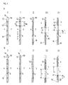
- Fig. 1 shows a schematic representation of the different opening phases (0, I, II, III and IV) two exemplary embodiments A and B of the platform door system 1 according to the invention.
- a platform door system 1 is schematically between the Track body 3 and the platform 4 shown in plan view.
- a barrier 10 exists from individual shut-off elements 12 of constant width 13, each in both directions are movable. With 13a the center distance between the shut-off elements is designated, i.e. the width 13 is plus the clear distance between an adjacent one Shutoff.
- Two locking and guide pins 14 are one on each top Shut-off element 12 provided. These locking and guide bolts 14 are in one fixed guide rail 16 introduced. There is also a second one parallel to the track body Provide guide rail 16 in which the shut-off elements can be moved.
- the shut-off elements 12 are aligned along the edge of the platform.
- the Shut-off elements 12 are locked by the locking and guide bolts 14.
- the Barrier 10 is closed, a passage from the area of the platform to the area Track body is not possible - even unintentionally.
- the platform area 4 is through the locked barrier 10 particularly pressure protected, so that even fast moving trains Station can pass.
- phase I the shut-off elements are unlocked, i.e. that the locking and Guide bolts 14 have been withdrawn from the fixed locking position.
- the Shutdown 10 is still closed, but is no longer as extremely pressure protected as in phase 0.
- shut-off elements 12 are removed from the fixed guide rail 16 on the free guide rail 16 '. This is preferably done over short, in plan Offset devices lying perpendicular (that is to say transversely) to the guide rail 16 ', particularly prefers short rail elements.
- the barrier 10 is still closed; de Shut-off elements are now ready to be offset parallel to one another to release an opening become.
- phase III predetermined shut-off elements along the free guide rail 16 'shifted to create a preselected opening pattern.
- the barrier 10 has openings 5 between the platform 4 and the Track body area 3.
- phase IV the entire platform door system 1 along the platform edge Offset distance 9 shifted. It is possible that the barrier 10 around the Offset path 9 via an additional rail 16.2 underneath (not shown) is moved.
- Phases 0 to IV interact as follows when a train enters: At passing trains the platform door system 1 is in phase 0, is locked and secured against pressure. In normal operation, it is sufficient if the platform door system 1 is is in the unlocked state of phase I. If a train is expected to stop, then The platform door system 1 changes to the state of phase II. The change from phase I II is preferably accompanied acoustically and / or visually. So it makes sense, the introduction phase II with acoustic warning signals such as beeps and orange lights. When the incoming train is almost rolled out, the platform door system 1 goes into phase III transferred, i.e. that the shut-off elements 12 open at the predetermined locations.
- the openings 5 of the barrier 10 and the are then at a standing train opening doors of the train opposite. If the train missed its ideal stop, is in the optional phase IV the barrier 10 to the corresponding malfunction of the Train, i.e. around the offset distance 9 - corrected. This is preferably done slowly and in the train's coasting phase, i.e. while this along the barrier in the station slides and rolls out.
- the individual phases 0 to IV are generally identical to those of the Embodiment A.
- the shut-off elements are on the two Guide rails 16 'and 16 "offset. This makes it possible to close each shut-off element move.
- This has the advantage in particular in phase III that it is possible to wait where the train actually stops and then the door system open according to the real location of the train without one slipped train would have to make up the entire barrier 10.
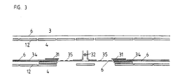
- FIG. 2a shows an opening image of a further exemplary embodiment of the invention Platform door system shown.
- This is a platform door system that manages with only one guide rail 16.
- the individual shut-off elements 12 are at Opening the barrier 10 to the right and to the left and pulled apart openings 5 are left at predetermined positions.
- the emerging on both sides Excess shut-off elements are either beyond the length of the station moved further along the track body into a stowage area 18 or into a corresponding one provided magazine 19 spent.
- FIG. 2b shows a barrier 10 according to the invention, in which the individual Shut-off elements 12 are placed on a rail 16 'and the opening pattern according to a of the embodiments of FIG. 1 can be generated.
- this preferred Embodiment can be dispensed with a storage area 18 or a magazine 19.
- platform barriers 10a are advantageous provided that can be opened for maintenance purposes for the operating personnel in the Operation preferably remain closed.
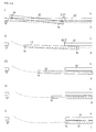
- FIG. 3 shows a schematic illustration of two opening phases of the exemplary embodiments of the platform door system according to the invention shown in FIG. 1.
- a Opening image generated in which the coupling 32 of the train 30 with a shut-off element 12 is covered to also cover this danger area.
- the remaining Barrier elements 12 adapt to the door picture of the standing train.
- FIG. 4a, b and c are schematic representations of the different opening phases three embodiments of shut-off elements 12 of the invention Platform door system 1 shown.
- shut-off element 12 pivoting of the shut-off element 12 along a curve (dashed line shown).
- a first phase I the shut-off element 12 becomes light rotated about its central axis until its front edge is behind the rear edge of the Neighboring element 12 'is located, and then in phases II to V behind adjacent shut-off element 12 'pivoted. This eliminates any risk of injury to Avoided passengers.
- facings 17 are preferably additionally provided do not allow that when pivoting the shut-off elements 12 objects in the minimal swivel range. Facings 17 are preferred It is planned to achieve pressure tightness in phase 0.
- shut-off element 12 is tilted about a central axis and then behind that adjacent shut-off element 12 'moved. This is particularly advantageous when on there is sufficient space on the platform side and in the track area.
- Fig. 4c it is shown how the shut-off element 12 first perpendicular to the line along the Barrier 10 is displaced in order to then parallel to the adjacent barrier element 12 ' to be moved.
- shut-off elements 12 and drive devices or motors 23 show a preferred combination of shut-off elements 12 and drive devices or motors 23.
- Each drive device with motor 23 can either unlock or move two elements 12.
- the motors 23 1 and 23 3 move the shut-off elements 12b and 12c by a maximum of one shut-off element width to the left and right after unlocking the locking devices 14.
- motor 23 (x) or motor 23 (x + 1) comes into action.
- the shut-off element 12 (y) can be moved either to the left or to the right.
- the motor thus has a physically favorable position for moving the elements 12.
- Fig. 4e the embodiment of Fig. 4d is in detail for a shut-off element 12 (y) in Interaction with the shut-off elements 12 (y-1) and 12 (y + 1) shown.
- FIG. 5 is a plan view of an embodiment of the invention Platform door system with a sinusoidal groove structure shown as a guide.
- the Shut-off elements 12 are here in sinusoidal groove structures of the guide rail 16 introduced and can be directly along this sinusoidal guide rail be moved.
- Fig. 6a is a side view of an embodiment of shut-off elements 12 of the Platform door system 1 according to the invention in the open state. This Embodiment corresponds to that of Fig. 4b.
- the shut-off elements 12 are first through a rotary motion pivoted about its central axis and then behind the neighboring one Shut-off elements 12 'pushed.
- the platform door system 1 of FIG. 6a is perpendicular to the cross section Track body and platform shown.
- the shut-off element 12 is in one Guide device 16 suspended.
- Locking bolts 14 are on the shut-off element 12 provided to anchor the shut-off element 12 in the guide device 16.
- the Guide device 16 extends to the clearance profile of the train 33, which the Borderline of the clearance profile in the drawing as a dashed line. 6a thus remains for the individual Shut-off elements 12 enough space to behind the guide device 16 adjacent shut-off elements in the space between the clearance profile of the train 33 and the non-shifted shut-off elements 12 to be moved.
- Fig. 7 shows a plan view of drive devices to demonstrate the possible Types of drives for opening a door leaf or moving a shut-off element. 7 is divided into FIGS. 7a to 7d.
- Fig. 7a is a barrier 10 consisting of individual shut-off elements 12 according to the present invention.
- the single ones Shut-off elements 12 each have two locking devices 14.
- Fig. 7b the shut-off elements 14 are shown with a drive facial expression.
- Drive wheels 24 are from the motor 23 via a drive transmission means 25, for example one Timing belt, driven.
- Deflection rollers 28 span the range of motion of the individual Drive elements on.
- Pins 26 are inserted into a latching device 29.
- the motor 23, the shut-off element 12, which is provided for opening, can be provided via a toothed belt 25 grasp and move so far that the required opening width is released.
- Fig. 7c it is shown how a shut-off element 12 by means of the drive wheel 24 and the Timing belt 25 has been moved behind an adjacent shut-off element. Is preferred the maximum opening width occurring is represented by two shut-off elements 12.
- a platform door system has thus been provided that flexibly opens images for can create different door pictures and trains and compensates for the slipping effect.
Description
Die Erfindung betrifft ein Bahnsteigtürensystem gemäß Oberbegriff des Anspruchs 1 und insbsondere ein flexibles
Bahnsteigtürensystem für Bahnhöfe, in denen automatisch gesteuerte und/oder automatisch
gesteuerte und führerlose Züge verkehren. Darüber hinaus betrifft die vorliegende Erfindung
ein Verfahren zur Steuerung dieses flexiblen Bahnsteigtürensystems. Ein gattungsgemäßes
Bahnsteigtürensystem ist aus der EP 0 525 738 A bekannt.The invention relates to a platform door system according to the preamble of
Beim Einsatz von führerlosen Zügen, die beispielsweise durch einen Computer gesteuert werden, ist die Einfahrt in einen Bahnhof eine sicherheitstechnisch bedeutende Phase. Es kann hier zu schweren Unfällen kommen, wenn wartende Passagiere in den Bereich der Gleiskörper gelangen, da der ferngesteuerte Zug auf solche Ereignisse nicht zuverlässig reagieren kann oder hierfür zusätzliche, in der Regel externe Maßnahmen erforderlich sind.When using driverless trains, for example controlled by a computer entering a train station is a safety-relevant phase. It can here serious accidents occur when waiting passengers in the area of Track bodies arrive because the remote-controlled train is not reliable on such events can react or additional, usually external measures are required for this.
Darüber hinaus besteht im größten Teil der bekannten Bahn- und Metrosysteme das Problem, daß in einem Bahnhof mehrere verschiedene Zugtypen und verschiedenes Rollmaterial halten müssen, die unterschiedliche Türbilder aufweisen. Daneben kommt es vor, daß die Haltegenauigkeit eines Zuges aufgrund von äußeren Einflüssen (Witterung, Luftfeuchtigkeit, Glätte, etc.) nicht ausreicht, um genau an einer vorbestimmten Stelle zu halten (sogenannter "Durchrutscheffekt").In addition, in most of the known rail and metro systems there is the problem that several different train types and different rolling stock stop in a station must have different door images. It also happens that the Stopping accuracy of a train due to external influences (weather, humidity, Smoothness, etc.) is not sufficient to hold exactly at a predetermined point (so-called "Slip" effect).
In der DE-OS 24 62 031 wird beschrieben, daß eine Station für automatische Bahnen ein vorgezogenes Gitter mit Geländer aufweist. Hierdurch ist aber noch nicht sichergestellt, daß Passagiere nicht auf den Gleiskörper gelangen; insbesondere besteht weiterhin die Gefahr, daß Körperteile durch die Gitter in den Gleiskörperraum und in das Lichtraumprofil des Zuges eindringen können. DE-OS 24 62 031 describes that a station for automatic webs preferred grid with railings. However, this does not yet ensure that Passengers do not get on the track body; in particular, there is still a risk that Body parts through the grids into the track body area and into the gauge of the train can penetrate.
In der DE-OS 31 32 296 wird eine Sicherheitstrennwand auf Bahnsteigen beschrieben, die korrespondierende Schiebetüren aufweist. Diese Sicherheitstrennwand ist eine feste bauliche Maßnahme und weist in den Wänden Spalte auf, in die jeweils nur eine bestimmte Schiebetür eingeschoben wird. Diese Wand erfordert den Betrieb von Zügen mit ebenfalls feststehendem Türbild.DE-OS 31 32 296 describes a safety partition on platforms that has corresponding sliding doors. This safety partition is a fixed structural one Measure and has gaps in the walls, in each of which only a certain sliding door is inserted. This wall requires the operation of trains with also fixed Door image.
In der DE-OS 32 14 602 wird ein Transportsystem beschrieben, bei dem mit zwei Absperrungen auf dem Bahnsteig drei Bereiche geschaffen werden, durch die der Fahrgaststrom geleitet werden kann. Bei diesem System sind die Öffnungen in den Absperrungen ortsfest vorgesehen.DE-OS 32 14 602 describes a transport system in which two Barriers on the platform are created three areas through which the Passenger flow can be directed. In this system, the openings are in the Barriers provided fixed.
In der DE 692 04 934 wird ein "Falttürapparat für Plattform für Gleisfahrzeuge" beschrieben. Hier werden Faltelemente in den Bahnsteigbereich hinein oder heraus gefaltet, was zu Gefahrenpunkten für die Passagiere auf dem Bahnsteig führen kann.DE 692 04 934 describes a "folding door apparatus for platform for rail vehicles". Here folding elements are folded in or out of the platform area, which leads to Danger points for passengers on the platform can lead.
Aufgabe der vorliegenden Erfindung ist es daher, ein gattungsgemäßes Bahnsteigtürenssystem derart weiterzubilden daß es geeignet ist, die Druckwelle eines durchfahrenden Zuges aufzunehmen und von auf dem Bahnsteig wartenden Passagieren fernzuhalten.The object of the present invention is therefore to develop a generic platform door system in such a way that it is suitable to absorb the pressure wave of a passing train and keep away from passengers waiting on the platform.
Diese Aufgabe wird durch das Verfahren und die Vorrichtung nach den unabhängigen Ansprüchen gelöst. Weitere vorteilhafte Ausgestaltungen sind in den abhängigen Ansprüchen angegeben.This task is achieved by the method and the device according to the independent Claims solved. Further advantageous configurations are in the dependent claims specified.
Gemäß einem Aspekt der Erfindung wird ein Bahnsteigtürensystem 1 geschaffen, das eine Absperrung
(10) umfaßt, die Absperrelemente (12) umfaßt, die entlang eines Gleiskörpers (3) und/oder eines
Bahnsteiges (4) ausrichtbar sind, wobei die Absperrelemente (12) gegeneinander so verschiebbar
sind, daß sie miteinander zumindest teilweise in Deckung gebracht werden können, wodurch
frei definierbare, vorbestimmte Öffnungen (5) und Öffnungsgrößen entlang des Gleiskörpers (3)
und/oder des Bahnsteiges (4) geschaffen werden können. Durch das Verschieben der einzelnen
Absperrelemente gegeneinander werden Gefahren vermieden, da hier kein Passagier beim
Öffnungs- oder Schließvorgang des Bahnsteigtürensystems eingeklemmt oder verletzt werden
kann. Gleichzeitig handelt es sich bei den erfindungsgemäßen Bahnsteigtürsystemen um
flexible Systeme, die jedes beliebige Türöffnungsbild erzeugen können, da sie ohne fest
installierte Bauteile auskommen. Dies ist insbesondere dann vorteilhaft, wenn verschiedene
Zugtypen - sei es aufgrund von verschieden alten (zum Teil verschieden gebauten)
eingesetzten Zügen, sei es aufgrund der unterschiedlichen Nutzung eines Bahnsteiges für
verschiedene Zugtypen (zum Beispiel: Nahverkehr mit vielen breiteren Türen, Fernverkehr
mit wenigen schmalen Türen) - auf demselben Bahnsteig nacheinander halten sollen. Fest installierte
Wandstücke und Schiebetüren würden hier je nach Zugtyp verschiedene Zugtüren
verdecken und ein Aussteigen an diesen Stellen unmöglich machen. Durch das flexible
System der vorliegenden Erfindung kann auch in einem Notfall oder bei einem
unplanmäßigen Halt an einer nicht dafür vorgesehenen Stelle auf dem Bahnsetig ein mit dem
aktuellen Standort des Zuges und seiner zu öffnenden Türen korrespondierendes Öffnungsbild
erzeugt werden. In der Folge blockieren sich Investitionen in Bahnsteigsicherheit und in neues
Rollmaterial nicht mehr gegenseitig.According to one aspect of the invention, a
Vorteilhafterweise sind bei dem Bahnsteigtürensystem der vorliegenden Erfindung die Absperrelemente (12) tafelförmig ausgebildet. Besonders bevorzugt sind die Absperrelemente (12) rechteckig ausgebildet. Durch eine tafelförmige, d.h. plane Ausbildung können die Absperrelemente leicht gegeneinander verschoben werden. Durch die rechteckige Ausbildung können die Absperrelemente vollständig in Deckung gebracht werden und sie geben dabei einen geeigneten Raum für den Durchgang von Passagieren frei. Es kann auch daran gedacht werden, die Absperrelemente in Form von dreieckigen Flächen vorzusehen, die wie eine Blendenöffnung gegeneinander verschoben werden können. Es kann ebenfalls daran gedacht werden, die Absperrelemente im Grundriß gekrümmt auszubilden. Dies ist insbesondere bevorzugt bei gekurvten Bahnsteigen bzw. gekurvten Bahnsteigkanten. Es kann ebenfalls daran gedacht werden, die Elemente als Polygonzug auszubilden. Dies ist dann bevorzugt, wenn die Bahnsteigkante gekrümmt ausgebildet ist.Advantageously, in the platform door system of the present invention Shut-off elements (12) are tabular. The shut-off elements are particularly preferred (12) rectangular. By a tabular, i.e. plan training can Shut-off elements can be easily moved against each other. Due to the rectangular shape the shut-off elements can be completely covered and they give a suitable space for the passage of passengers free. It can also be thought of be to provide the shut-off elements in the form of triangular surfaces that like a Aperture can be moved against each other. It can also be thought of are to form the shutoff elements curved in plan. This is particularly so preferred for curved platforms or curved platform edges. It can also be considered to form the elements as a polygon. This is preferred if the platform edge is curved.
Auch an eine in der Ansicht rautenförmige Ausbildung der Elemente kann gedacht werden, um Bahnsteigkanten von in Steigung errichteten Bahnhöfen (mit geneigter Oberfläche) abzusichern. Besonders bevorzugt ist eine Ausführungsform vorgesehen, bei der in der Ansicht schmale, längliche und/oder lamellenförmige Absperrelemente vorgesehen sind, die an Bahnhöfen mit im Verlauf der Bahnsteigkante sich verändernder Steigung anpaßbar sind und einen flexiblen Bahnsteigabschluß bilden.A diamond-shaped design of the elements can also be considered, around platform edges of stations built on a slope (with an inclined surface) secure. An embodiment is particularly preferably provided in which View narrow, elongated and / or lamellar shut-off elements provided are at stations with a gradient that changes along the edge of the platform are adaptable and form a flexible platform closure.
Ein weiteres Ausführungsbeispiel des vorliegenden Bahnsteigtürensystems zeichnet sich dadurch aus, daß die Absperrelemente (12) transparente Materialien enthalten; insbesondere, daß die Absperrelemente (12) überwiegend Glas und/oder Acrylate enthalten; insbesondere vollständig aus transparenten Materialien bestehen. Dadurch können beim Einfahren des Zuges die Passagiere schon den Zug sehen und abschätzen, wo Türen geöffnet werden und wo nicht. So wird die Gefahr von Unfällen reduziert, da ein überraschendes Öffnen weitgehend vermieden wird. Darüber hinaus wird so auch den beförderten Passagieren insbesondere in einer unterirdischen Bahn die Gelegenheit geboten, sich zumindest im Moment des Einfahrens des Zuges und beim Halt über die derzeitige Haltestelle zu informieren und einen Eindruck zumindest des Bahnsteiges zu gewinnen, sich zu orientieren und damit subjektive Sicherheit zu gewinnen. Bevorzugt wird hierbei die statische Eigentragwirkung dieser transparenten Materialien genutzt. Besonders bevorzugt sind zusätzlich mechanische Teile in das transparente Material eingelassen. Diese mechanischen Teile sind bevorzugt Teile, die eine andere Festigkeit und/oder ein anderes Elastizitätsmodul aufweisen. Hierdurch können spezielle Bereiche der Absperrelemente zusätzlich an hohe Abnutzung, Reibungskräfte, Verwindung oder Bruchbeanspruchung angepaßt werden. Die Materialien sind bevorzugt aus der Gruppe Metalle, Kunststoffe, die hohe Beanspruchungen aufnehmen könne - insbesondere Acrylate - keramische Materialien oder Kombination hiervon.Another embodiment of the present platform door system stands out characterized in that the shut-off elements (12) contain transparent materials; in particular, that the shut-off elements (12) predominantly contain glass and / or acrylates; in particular consist entirely of transparent materials. As a result, when retracting the The passengers can already see the train and estimate where the doors are opened and where Not. This reduces the risk of accidents, since a surprising opening is largely possible is avoided. In addition, the passengers carried in particular in an underground train was given the opportunity, at least at the moment of entering of the train and at the stop about the current stop and to inform you To gain an impression of at least the platform, to orientate and thus subjective Gain security. The static self-supporting effect of this is preferred transparent materials. In addition, mechanical parts in are particularly preferred the transparent material embedded. These mechanical parts are preferably parts that have a different strength and / or a different modulus of elasticity. This can special areas of the shut-off elements high wear, frictional forces, torsion or breaking stress be adjusted. The materials are preferred from the group of metals, plastics, can take high loads - especially acrylates - ceramic materials or a combination thereof.
Bei einem weiteren vorteilhaften Ausführungsbeispiel der Erfindung ist ein Bahnsteigtürensystem vorgesehen, bei dem die Absperrelemente (12) gegeneinander versetzbar sind. Insbesondere ist ein Bahnsteigtürensystem vorgesehen, bei dem die Absperrelemente (12) senkrecht einer Linie entlang des Gleiskörpers (3) und/oder des Bahnsteiges (4) versetzbar sind. Durch diese leichte Versetzung der Absperrelemente gegeneinander kann in einer frühen Phase das System in eine Operationsstellung gebracht werden, aus der heraus das eigentliche Öffhungsbild schnell hergestellt werden kann. Gleichzeitig dient diese Phase der Warnung der wartenden Passagiere, die nun damit rechnen können, daß der Zug bald einfährt. Bevorzugt wird eine solche Phase auch akustisch und/oder visuell begleitet, d.h. daß in dieser Phase akustische Signale oder bevorzugt farbige Lichtsignale über den bevorstehenden Öffnungsvorgang informieren.In a further advantageous embodiment of the invention is a platform door system provided, in which the shut-off elements (12) can be displaced relative to one another. In particular, a platform door system is provided, in which the shut-off elements (12) perpendicular to a line along the track body (3) and / or the platform (4) are displaceable. Due to this slight displacement of the shut-off elements against each other in an early Phase the system are brought into an operating position, from which the actual Opening picture can be made quickly. At the same time, this phase serves to warn the waiting passengers who can now expect the train to arrive soon. Prefers is such a phase also accompanied acoustically and / or visually, i.e. that at this stage acoustic signals or preferably colored light signals over the upcoming Inform the opening process.
Bei einem vorteilhaften Ausführungsbeispiel ist zumindest ein Absperrelement verkippbar und/oder versenkbar und/oder hochziehbar ausgebildet. Damit können einzelne Absperrelemente unter die Bahnsteigkante versenkt werden. Es ist außerdem möglich, die Absperrelemente auf eine Höhe hochzuheben, die ein Passieren der Passagiere ermöglicht. Dadurch ist eine genaue Anpassung der Öffnungen an die Geometrie der Türen nicht nur zur Seite, sondern auch nach unten und nach oben möglich.In an advantageous embodiment, at least one shut-off element can be tilted and / or designed to be retractable and / or pullable. Individuals can Barrier elements are sunk under the platform edge. It is also possible that Raise the barrier elements to a height that allows passengers to pass. This means that the openings are not only precisely adapted to the geometry of the doors Side, but also down and up possible.
Erfindungsgemäß umfasst das Bahnsteigtürensystem der vorliegenden Erfindung bevorzugt Absperrelemente (12) unterschiedlicher Breite. Durch Absperrelemente unterschiedlicher Breite können optimale Kombinationen von Absperrelementen je nach erwarteten Zügen für den Bahnhof eingesetzt werden. Es kann dadurch die zu bewegende Masse an Absperrelementen so gering wie nötig gehalten werden. Bei speziellen Konstellationen von Zügen und Bahnsteig respektive bei einem bestimmten Türbild kann auch eine konstante Breite der Absperrelemente bevorzugt sein.According to the platform door system comprises the The present invention prefers shutoff elements (12) of different types Width. Optimal combinations of Barrier elements depending on the expected trains for the station. It can thereby the mass to be moved on shut-off elements are kept as low as necessary. For special constellations of trains and platforms or for a specific one A constant width of the shut-off elements can also be preferred.
Erfindungsgemäß sind die Absperrelemente (12) entlang des Gleiskörpers (3) und/oder des Bahnsteiges (4) - d.h. entlang der Bahnsteigkante - verschiebbar, insbesondere durch einen Zug verschiebbar, insbesondere mitnehmbar. Beim Einfahren kann es zum Durchrutschen des Zuges kommen, beispielsweise wenn der Gleiskörper naß oder mit Laub bedeckt ist. Der Zug rutscht dann über den eigentlich vorgesehenen Haltepunkt hinaus. Durch die Verschiebbarkeit der gesamten Absperrung wird dieser Durchrutscheffekt kompensiert, da hierbei die gesamte Absperrung (mit dem vorprogrammierten Öffnungsbild) dem Zug hinterhergeführt wird, so daß die Öffnungen wieder genau den Türpositionen gegenüberstehen. Besonders bevorzugt nimmt der durchrutschende Zug einen Mitnehmer über den Durchrutschweg mit, der entweder direkt mit der Absperrung gekoppelt ist und die Absperrung gleich mit dem Zug mitnimmt oder zeitverzögert um diese Strecke nachführt. Besonders bevorzugt kann die überschüssige Energie des durchrutschenden Zuges eingesetzt werden, um die Absperrung mitzunehmen.According to the invention, the shut-off elements (12) along the track body (3) and / or the platform (4) - i.e. along the platform edge - displaceable, in particular displaceable by a train, in particular entrained. When entering, the train may slip, for example if the track body is wet or covered with leaves. The train then slides over the intended breakpoint beyond. Due to the movability of the entire barrier this slipping effect compensates, since the entire barrier (with the pre-programmed Opening picture) is followed the train, so that the openings again face exactly the door positions. The slipping is particularly preferred Train a driver along the slipway with either the barrier directly is coupled and the barrier takes it with the train or delayed by it Track route. The excess energy of the slipping can be particularly preferred Zuges are used to take the barrier with you.
Bei dem Bahnsteigtürensystem der vorliegenden Erfindung weisen die Absperrelemente (12) Verriegelungsvorrichtungen (14) und/oder Abdichtvorrichtungen (15) auf. Die Verriegelungsvorrichtung erlaubt es, die Absperrelemente zusätzlich zu fixieren und zu stabilisieren. Dadurch kann die Absperrung verstärkt werden, wenn es darum geht, die Druckwelle eines durchfahrenden Zuges, insbesondere eines mit hoher Geschwindigkeit durchfahrenden Zuges - aufzunehmen und von den auf dem Bahnsteig wartenden Passagieren fernzuhalten. Darüber hinaus können vorteilhafterweise auch Abdichtvorrichtungen vorgesehen sein, die es erlauben, die Absperrung des Bahnsteiges von dem Gleiskörper auch geruchsdicht oder gasdicht, hermetisch gegen den Gleiskörperraum abzudichten. Dadurch ist es möglich, eine geordnete klimatische Regelung auf den Bahnsteigen zu erreichen; ohne daß die klimatischen Einflüsse der Umgebung über den Gleiskörperraum stören. Insbesondere ist es dadurch auch möglich, Bahnsteige hermetisch abzudichten, wenn dies aufgrund von Feuer-, Smog- oder Giftalarm, insbesondere in unterirdischen Bahnhöfen, wünschenswert erscheint. Bevorzugt wird dadurch ein Klimatisieren von Bahnhöfen bzw. Bahnsteigen erleichtert.In the platform door system of the present invention the shut-off elements (12) locking devices (14) and / or sealing devices (15) on. The locking device allows the blocking elements to be additionally fixed and to stabilize. This can reinforce the barrier when it comes to the Blast wave of a passing train, especially one at high speed passing train - to be picked up by the passengers waiting on the platform keep. In addition, sealing devices can advantageously also be provided that also allow the platform to be blocked off from the track body odor-tight or gas-tight, hermetically sealed against the track body area. This is it is possible to achieve an orderly climatic regulation on the platforms; without disrupt the climatic influences of the environment via the track body area. In particular is it is also possible to hermetically seal platforms if this is due to fire, Smog or poison alarm, especially in underground train stations, seems desirable. This preferably makes air conditioning of train stations or platforms easier.
Vorzugsweise ist, insbesondere bei verschiedenen Wagenbreiten, eine Verschiebemöglichkeit der gesamten Wand aus Absperrelementen orthogonal/rechtwinklig zur Bahnsteigkante vorgesehen. Damit kann der geöffnete Zug gegenüber dem Raum um den Gleiskörper abgedichtet werden. Bevorzugt werden die zu öffnenden Zwischenräume zwischen den Türen des eingefahrenen Zuges und den Absperrelementen als Schleuse vor dem Öffnen ausgeblasen.Preferably, especially in the case of different carriage widths, there is a possibility of displacement the entire wall of barrier elements orthogonal / perpendicular to the platform edge intended. This allows the open train to face the space around the track body be sealed. The spaces between the doors that are to be opened are preferred the retracted train and the shut-off elements as a lock before opening blown out.
Besonders bevorzugt umfaßt die Verriegelungsvorrichtung (14) mindestens einen Bolzen. Jeweils ein Bolzen kann an einem Ende der Schmalseite der Absperrvorrichtung vorgesehen sein, so daß je rechteckigem Absperrelement 4 Bolzen vorgesehen sind. Diese Bolzen können dann als Führungsstifte in einer Führung zur Verschiebung der Absperrelemente dienen und im Falle der Verriegelung in dafür vorgesehene Aussparungen in den Führungen erstreckt werden und dadurch das Absperrelement in der Führung verriegeln. Die Abdichtvorrichtung (15) ist bevorzugt eine aufweitbare Kunststoffwulst. Dadurch ist es möglich, durch Beaufschlagung dieser Wulst mit einem Medium wie Luft oder Öl eine Anpressung derselben an die Absperrelemente zu erreichen, wodurch eine hermetische Abdichtung erreicht wird. Zusätzlich kann im Bahnsteig eine Vorrichtung zur Erzeugung eines Überdrucks vorgesehen sein, um im Falle einer nicht optimalen Abdichtung ein Eindringen von unerwünschten Gasen in den Bahnsteigraum zu vermeiden.The locking device (14) particularly preferably comprises at least one bolt. A bolt can be provided at one end of the narrow side of the shut-off device be so that 4 bolts are provided for each rectangular shut-off element. These bolts can then serve as guide pins in a guide for moving the shut-off elements and in the case of locking in the recesses provided in the guides and thereby lock the shut-off element in the guide. The sealing device (15) is preferably an expandable plastic bead. This makes it possible to apply it this bead with a medium such as air or oil pressing the same against the To reach shut-off elements, whereby a hermetic seal is achieved. In addition, a device for generating an overpressure can be provided in the platform to prevent the ingress of undesirable gases in the event of a non-optimal sealing to avoid in the platform area.
Bei einem weiteren vorteilhaften Bahnsteigtürensystem der vorliegenden Erfindung ist eine Steuervorrichtung (20) vorgesehên, die Antriebsvorrichtungen (21) ansteuert, die die Absperrelemente (12) in eine vorbestimmte Position versetzen und/oder verschieben können. Durch diese Steuervorrichtung können die einzelnen Absperrelemente so angeordnet werden, daß das gewünschte Öffnungsbild erzeugt wird. Bevorzugt kann diese Steuervorrichtung auch die Absperrelemente versetzen, um sie anschließend leichter verschieben zu können. Diese Antriebsvorrichtungen können Motoren, insbesondere elektrische Motoren, Führungen, Kettenzüge, Zahnriemen aus Metall oder bevorzugt Kunststoff, aber auch sogenannte Spindelantriebe oder pneumatische bzw. hydraulische Antriebe für die Absperrelemente umfassen. Die Antriebsvorrichtungen können oberhalb, unterhalb oder seitlich der jeweils zu bewegenden Absperrelemente angeordnet werden. Another advantageous platform door system of the present invention is one Control device (20) provided, the drive devices (21) which drives the Shut off elements (12) in a predetermined position and / or can move. With this control device, the individual shut-off elements can be arranged that the desired opening image is generated. Preferably, this control device can also move the shut-off elements so that they can then be moved more easily. This Drive devices can motors, especially electric motors, guides, chain hoists, Timing belts made of metal or preferably plastic, but also so-called Spindle drives or pneumatic or hydraulic drives for the shut-off elements include. The drive devices can be above, below or to the side of each Moving shut-off elements are arranged.
Bei einem weiteren bevorzugten Bahnsteigtürensystem dieser Erfindung können die Absperrelemente (12) mit einer Widmung versehen werden. Insbesondere können sie zumindest in einem vorbestimmten Bereich eine vorbestimmte Farbe annehmen. Der vorbestimmte Bereich kann bevorzugt eine zur Passagierleitung günstige Form oder Figur annehmen, beispielsweise können Pfeile oder Verkehrszeichen dargestellt werden. Diese Widmungen können statisch oder bevorzugt auch animiert sein, d.h. sich zeitlich verändern. Somit können bevorzugt sich ändernde Texte und abwechselnde Hinweise dargestellt werden.In another preferred platform door system of this invention, the Shut-off elements (12) are provided with a dedication. In particular, at least they can assume a predetermined color in a predetermined area. The predetermined one The area can preferably assume a shape or figure which is favorable for the passenger line, for example, arrows or traffic signs can be displayed. These dedications can be static or preferably animated, i.e. change over time. So you can preferably changing texts and alternating notes are displayed.
Es können somit gewisse Absperrelemente vor oder bei der Einfahrt des Zuges mit einer Widmung versehen werden, die anzeigt, daß in diesem Bereich eine Tür öffnen wird. Außerdem kann angezeigt werden, daß in diesem Bereich Passagiere nur aussteigen, aber nicht einsteigen können oder umgekehrt. Diese Widmung kann auf die Absperrelemente projiziert werden. Diese Widmung kann auch durch akustische Signale erfolgen. Bevorzugt nehmen Bereiche der Absperrelemente verschiedene Farben an, mit denen sie den Passagier über den einfahrenden Zug und das Türbild bzw. das Öffnungsbild informieren. So können bevorzugt grüne Farbtöne verwendet werden, um anzuzeigen, wo eingestiegen werden kann und rote Farbtöne, wo nur ausgestiegen wird. Gelbe oder orange Farbtöne können Bereiche kennzeichnen, in denen nicht mit einer Öffnung gerechnet werden kann. Bei zumindest teilweise transparenten Absperrelementen können die Widmungen auch auf der dem Bahnsteig gegenüberliegenden Seite dargestellt werden; insbesondere durch Projektion der Widmungen auf eine dort vorhandene Wand. Diese Widmung kann auch bewegte Bilder umfassen.It can thus certain shut-off elements before or when the train enters with a Dedication indicating that a door will open in this area. It can also be indicated that passengers in this area only get out, however can't get in or vice versa. This dedication can affect the shut-off elements be projected. This dedication can also be done by acoustic signals. Prefers areas of the barrier elements take on different colors with which they pass the passenger Inform about the incoming train and the door picture or the opening picture. So can preferably green tones are used to indicate where to board and red tones where you only get out. Yellow or orange hues can be areas mark in which an opening cannot be expected. At least partially transparent shut-off elements, the dedications can also on the Platform opposite side are shown; especially by projecting the Dedications to an existing wall there. This dedication can also be moving pictures include.
Darüber hinaus kann daran gedacht werden, auf den Absperrelementen oder Teilen davon Werbung darzustellen. Es ist ebenfalls denkbar, die Absperrelemente oder Teile davon zur interaktiven Nutzung durch die wartenden Passagiere vorzusehen, die über berührungssensible Flächen mit einem vorbestimmten System kommunizieren können, und dadurch beispielsweise einkaufen oder zum Beispiel Opernkarten, Bahnfahrkarten etc. bestellen können, oder daß Information über Reiseweg, Reisezeit über das interaktive System eingeholt werden kann. Bevorzugt sind die Absperrelemente oder Teile davon als berührungssensible Flächen ausgebildet, insbesondere sind bevorzugt Absperrelemente oder Teile davon als LCD-Flächen ausgebildet. In Flächen oder Teilen von den Absperrelementen entstehen so Bilder, die die wartenden Passagiere informieren oder unterhalten können. Es kann ebenfalls daran gedacht werden, Sicherheitsinformationen oder Anweisungen zur Sicherstellung des geordneten Bahnhofsablaufs über die Absperrelemente darzustellen.In addition, it can be thought of on the shut-off elements or parts thereof To display advertising. It is also conceivable for the shut-off elements or parts thereof provide interactive use by the waiting passengers that are touch sensitive Surfaces can communicate with a predetermined system, and thereby for example shopping or ordering opera tickets, train tickets etc. can, or that information about travel route, travel time obtained via the interactive system can be. The shut-off elements or parts thereof are preferably touch-sensitive Surfaces are formed, in particular shut-off elements or parts thereof are preferred LCD surfaces formed. This creates the surface or parts of the shut-off elements Images that can inform or entertain the waiting passengers. It can also be remembered to provide safety information or instructions to ensure that the to display orderly station sequence over the shut-off elements.
Bevorzugt ist eine Eingabeeinheit (22) vorgesehen, über die ein vorbestimmtes Bild an Öffnungen (5) vorgewählt werden kann. Die Eingabeeinheit (22) ist bevorzugt in einem Tunnel vor dem Bahnhof vorgesehen, wobei hier eine automatische Üertragung der Eingabedaten an das Bahnsteigtürensystem erfolgt. Besonders bevorzugt ist eine Eingabeeinheit in der Dispatcher- oder Leitzentrale vorgesehen und so ausgebildet, um automatisch transferierte Daten oder manuell eingegebene Daten an das Bahnsteigtürensystem weiterzuleiten. Dadurch wird dem Bahnsteigtürensystem das geforderte Öffnungsbild übergeben. Die Eingabeeinheit (22) wird bevorzugt mit Informationssignalen gespeist, die zu Charakteristika und/oder zur Belegung eines Zuges und/oder zur Belegung des Bahnsteiges (4) korrespondieren. So kann dem System das Türbild des einfahrenden Zuges übermittelt werden. Dem System kann auch mitgeteilt werden, welche Türen des Zuges nicht öffnen werden - und somit welche Bahnsteigüren sich nicht öffnen müssen. Dem System kann ebenfalls übermittelt werden, welche Passagierbelegung an den verschiedenen Türen zu erwarten ist. Auf diese Weise können die Widmungen eingespielt werden.An input unit (22) is preferably provided, via which a predetermined image is displayed Openings (5) can be selected. The input unit (22) is preferably in a tunnel provided in front of the station, with an automatic transmission of the input data the platform door system takes place. An input unit in the Dispatcher or control center provided and designed to automatically transfer Forward data or manually entered data to the platform door system. Thereby the required opening image is handed over to the platform door system. The input unit (22) is preferably fed with information signals which lead to characteristics and / or The occupancy of a train and / or the occupancy of the platform (4) correspond. So can the door image of the incoming train is transmitted to the system. The system can too be told which doors of the train will not open - and therefore which ones Platform doors do not have to open. The system can also be communicated what occupancy is to be expected at the different doors. In this way the dedications can be imported.
Bei einem weiteren Ausführungsbeispiel der vorliegenden Erfindung sind Bahnsteigtürensysteme vorgesehen, bei denen die Informationssignale über ein Barcodelesegerät vor dem Bahnsteig (4) gewonnen werden und/oder bei denen die Informationssignale über ein Monitorsystem im Zug gewonnen werden und /oder bei denen die Informationssignale über eine Eingabeeinrichtung, insbesondere eine Tastatur oder ein Grafiktableau, eingegeben werden. Durch diese Ausgestaltungen besteht die Möglichkeit, die für die Verkürzung der Wartezeiten beim Halt des Zuges erforderlichen Steuerungsparameter zu ermitteln und dem System zu übergeben, damit durch das optimale Öffnungsbild und die erforderliche Widmung der Bahnsteigtüren die Passagiere so früh als möglich über das zu erwartende Öffnungsbild informiert werden können. Insbesondere kann die Information durch ein Barcodelesegerät im Tunnel auf der Strecke oder unterhalb der Bahnsteigkante gegenüber der Außenseite des Zuges abgelesen werden. Dies eignet sich vor allem für unveränderte Information über den Zug selbst wie z.B. Türstellung der Wagen, Türbreiten/Öffnungsbreiten. Informationen über die Verteilung der Passagiere selbst lassen sich durch Videokameras im Inneren des Zuges gewinnen.In another embodiment of the present invention are platform door systems provided in which the information signals via a barcode reader be obtained in front of the platform (4) and / or in which the information signals via Monitor system can be obtained on the train and / or where the information signals are about an input device, in particular a keyboard or a graphic panel, entered become. Through these configurations there is the possibility of shortening the To determine waiting times when the train stops and the necessary control parameters System to be handed over, thus by the optimal opening image and the required dedication passengers of the platform doors as early as possible via the expected opening image can be informed. In particular, the information can be read by a barcode reader in the Tunnel on the route or below the platform edge opposite the outside of the Turn read. This is particularly suitable for unchanged information about the Train itself such as Door position of the wagons, door widths / opening widths. information about the distribution of the passengers themselves can be seen by video cameras inside the train win.
Ein weiteres bevorzugtes Bahnsteigtürensystem umfaßt bauliche Vorrichtungen (7, 8) vor und/oder hinter dem Bahnsteig, mit denen der Gleisraum abgetrennt werden kann, insbesondere hermetisch abgetrennt werden kann. Dadurch ist es möglich, insbesondere in Krisensituationen den gesamten Bahnhof abzuriegeln und bevorzugt unterirdische Bahnhöfe für den Zivilschutz einzusetzen. In Kombination mit entsprechenden baulichen Abriegelungsvorrichtungen am Eingang in die unterirdische Bahnstation können so im Stadtgebiet schnell erreichbare und effiziente Zivelschutzbauten bereitgestellt werden. Diese baulichen Vorrichtungen können verschiebbare Betonbauteile sein. Durch das Bahnsteigtürensystem wird eine nochmalige Abschirmung gegenüber dem Gleiskörper erreicht und somit eine Schleuse bereitgetsellt, durch die auch bei kurzfristigem Öffnen der baulichen Vorrichtungen ein Schutz des Bahnsteigraumes erhalten bleibt.Another preferred platform door system comprises structural devices (7, 8) and / or behind the platform with which the track area can be separated, in particular can be hermetically separated. This makes it possible, especially in Sealing off the entire station in crisis situations and prefers underground stations for civil defense. In combination with corresponding structural Locking devices at the entrance to the underground train station can be in the Rapidly accessible and efficient civil protection structures are provided. This Structural devices can be slidable concrete components. By the Platform door system is a further shield against the track body reached and thus provided a lock through which the protection of the platform area is preserved.
Die Aufgabe wird äußerdem durch ein Verfahren gelöst.The task is also accomplished through a process solved.
Im folgenden sollen weitere vorteilhafte Ausgestaltungen der Erfindung an Hand der Zeichnung erläutert werden. Hierbei zeigt
- Fig. 1
- eine schematische Darstellung der verschiedenen Öffnungsphasen zweier Ausführungsbeispiele des erfindungsgemäßen Bahnsteigtürensystems;
- Fig. 2
- Öffnungsbilder weiterer Ausführungsbeispiele des erfindungsgemäßen Bahnsteigtürensystems;
- Fig. 3
- eine schematische Darstellung zweier Öffnungsphasen der Ausführungsbeispiele des erfindungsgemäßen Bahnsteigtürensystems gemäß Fig. 1;
- Fig. 4
- eine schematische Darstellung der verschiedenen Öffnungsphasen dreier Ausführungsbeispiele von Absperrelementen des erfindungsgemäßen Bahnsteigtürensystems;
- Fig. 5
- eine Draufsicht auf ein Ausführungsbeispiel des erfindungsgemäßen Bahnsteigtürensystems mit einer sinusförmigen Rillenstruktur als Führung; und
- Fig. 6
- eine Seitenansicht auf ein Ausführungsbeispiel von Absperrelementen des erfindungsgemäßen Bahnsteigtürensystems im sich öffnenden Zustand;
- Fig. 7
- eine Draufsicht auf die Antriebsvorrichtung zur Demonstration der möglichen Antriebsphasen zur Öffnung eines Türflügels/Verschie-bung eines Absperrelementes.
- Fig. 1
- a schematic representation of the different opening phases of two embodiments of the platform door system according to the invention;
- Fig. 2
- Opening pictures of further exemplary embodiments of the platform door system according to the invention;
- Fig. 3
- a schematic representation of two opening phases of the embodiments of the platform screen door system according to the invention shown in FIG. 1;
- Fig. 4
- is a schematic representation of the different opening phases of three embodiments of shut-off elements of the platform door system according to the invention;
- Fig. 5
- a plan view of an embodiment of the platform door system according to the invention with a sinusoidal groove structure as a guide; and
- Fig. 6
- a side view of an embodiment of shut-off elements of the platform door system according to the invention in the opening state;
- Fig. 7
- a plan view of the drive device to demonstrate the possible drive phases for opening a door leaf / displacement of a shut-off element.
Fig. 1 zeigt eine schematische Darstellung der verschiedenen Öffnungsphasen (0, I, II, III und
IV) zweier Ausführungsbeispiele A und B des erfindungsgemäßen Bahnsteigtürensystems 1.
Im ersten Ausführungsbeispiel A ist ein Bahnsteigtürensystem 1 schematisch zwischen dem
Gleiskörper 3 und dem Bahnsteig 4 in der Draufsicht dargestellt. Eine Absperrung 10 besteht
aus einzelnen Absperrelementen 12 konstanter Breite 13, die jeweils in beide Richtungen
verschiebbar sind. Mit 13a ist der Achsabstand zwischen den Absperrelementen bezeichnet,
d.h. die Breite 13 ist zuzüglich des lichten Abstandes zwischen einem benachbarten
Absperrelement. Jeweils zwei Verriegelungs- und Führungsbolzen 14 sind je Oberseite eines
Absperrelementes 12 vorgeshen. Diese Verriegelungs- und Führungsbolzen 14 sind in einer
festen Führungsschiene 16 eingeführt. Daneben ist parallel zum Gleiskörper eine zweite
Führungsschiene 16 vorgeshen, in der die Absperrelemente verschiebbar sind.Fig. 1 shows a schematic representation of the different opening phases (0, I, II, III and
IV) two exemplary embodiments A and B of the
In der Phase 0 sind die Absperrelemente 12 entlang der Bahnsteigkante ausgerichtet. Die
Absperrelemente 12 sind durch die Verriegelungs- und Führungsbolzen 14 verriegelt. Die
Absperrung 10 ist geschlossen, ein Durchgang vom Bereich des Bahnsteiges zum Bereich der
Gleiskörper ist - auch unbeabsichtigt - nicht möglich. Der Bahnsteigbereich 4 ist durch die
verriegelte Absperrung 10 besonders druckgeschützt, so daß auch schnell fahrende Züge den
Bahnhof passieren können.In
In der Phase I werden die Absperrelemente entriegelt, d.h. daß die Verriegelungs- und
Führungsbolzen 14 aus der fixen Verriegelungsposition zurückgezogen wurden. Die
Absperrung 10 ist immer noch geschlossen, aber nicht mehr so extrem druckgeschützt wie in
der Phase 0.In phase I, the shut-off elements are unlocked, i.e. that the locking and
In der Phase II werden vorgewählte Absperrelemente 12 von der festen Führungsschiene 16
auf die freie Führungsschiene 16' versetzt. Dies erfolgt bevorzugt über kurze, im Grundriß
senkrecht (also quer) zur Führungsschiene 16' liegende Versatzeinrichtungen, besonders
bevorzugt kurze Schienenelemente. Die Absperrung 10 ist noch immer geschlossen; de
Absperrelemente sind nun aber bereit, zur Freigabe einer Öffnung längsparallel versetzt zu
werden.In phase II, preselected shut-off
In der Phase III werden vorbestimmte Absperrelemente entlang der freien Führungsschiene 16' verschoben, um ein vorgewähltes Öffnungsmuster zu erzeugen. In phase III, predetermined shut-off elements along the free guide rail 16 'shifted to create a preselected opening pattern.
Nun weist die Absperrung 10 Öffnungen 5 zwischen dem Bahnsteig 4 und dem
Gleiskörperbereich 3 auf.Now the
In der Phase IV wird das gesamte Bahnsteigtürensystem 1 entlang der Bahnsteigkante um die
Versatzstrecke 9 verschoben. Dabei ist es möglich, daß die Absperrung 10 um die
Versatzstrecke 9 über eine darunterliegende zusätzliche Schiene 16.2 (nicht eingezeichnet)
verschoben wird.In phase IV, the entire
Die Phasen 0 bis IV spielen bei der Einfahrt eines Zuges folgendermaßen zusammen: Bei
durchfahrenden Zügen befindet sich das Bahnsteigtürensystem 1 in Phase 0, ist verriegelt und
gegen Druck gesichert. Im Normalbetrieb reicht es aus, wenn das Bahnsteigtürensystem 1 sich
im entriegelten Zustand der Phase I befindet. Wird ein Zug, der halten soll, erwartet, dann
wechselt das Bahnsteigtürensystem 1 in den Zustand der Phase II. Der Wechsel von Phase I
zu II wird bevorzugt akustisch und/oder visuell begleitet. So bietet es sich an, die Einleitung
der Phase II mit akustischen Warnsignalen wie Piepstönen und Orangelicht anzukündigen.
Wenn der einfahrende Zug fast ausgerollt ist, wird das Bahnsteigtürensystem 1 in die Phase
III überführt, d.h. daß die Absperrelemente 12 an den vorbestimmten Stellen öffnen. Im
Idealfall stehen sich dann bei stehendem Zug die Öffnungen 5 der Absperrung 10 und die zu
öffnenden Türen des Zuges gegenüber. Falls der Zug seinen idealen Haltepunkt verfehlt hat,
wird in der optionalen Phase IV die Absperrung 10 um den entsprechenden Fehlstand des
Zuges, d.h. um die Versatzstrecke 9 - nachkorrigiert. Dies geschieht bevorzugt langsam und in
der Ausrollphase des Zuges, d.h. während dieser an der Absperrung entlang in den Bahnhof
gleitet und ausrollt.
Nachdem der Ein- und Aussteigevorgang abgeschlossen ist, können die einzelnen Phasen in
umgekehrter Reihenfolge wieder abgearbeitet werden, um das Bahnsteigtürensystem 1 wieder
in die geschlossene Konfiguration gemäß Phase I oder Phase 0 zu versetzen.After the boarding and alighting process is complete, the individual phases in
reverse order are processed again to the
Beim Ausführungsbeispiel B sind zwei flexible Führungsschienen 16' und 16" vorgesehen.
Die einzelnen Phasen 0 bis IV sind im allgemeinen identisch zu denen des
Ausführungsbeispieles A. In der Phase II werden die Absperrelemente jedoch auf die beiden
Führungsschienen 16' und 16" versetzt. Dadurch ist es möglich, jedes Absperrelement zu
verschieben. Dies hat insbesondere in der Phase III den Vorteil, daß gewartet werden kann,
wo der Zug tatsächlich zum Stehen kommt und anschließend wird das Türsystem
entsprechend des wirklichen Standortes des Zuges geöffnet, ohne daß bei einem
durchgerutschten Zug ein Nachholen der gesamten Absperrung 10 erforderlich wäre.
Bevorzugt kann aber auch bei dem Bahnsteigtürensystem 1 nach dem Ausführungsbeispiel B
in einer Phase IV die gesamte Absperrung 10 beim Ausrollen des Zuges entlang der beiden
Führungsschienen 16"und 16" mitgenommen werden.In embodiment B, two
In Fig. 2a wird ein Öffnungsbild eines weiteren Ausführungsbeispiels des erfindungsgemäßen
Bahnsteigtürensystems dargestellt. Hierbei handelt es sich um ein Bahnsteigtürensystem, das
mit nur einer Führungsschiene 16 auskommt. Die einzelnen Absperrelemente 12 werden beim
Öffnen der Absperrung 10 nach rechts und nach links auseinandergezogen und an den
vorbestimmten Stellen werden Öffnungen 5 frei gelassen. Die an beiden Seiten entstehenden
überschüssigen Absperrelemente werden entweder über die Länge des Bahnhofes hinaus
entlang der Gleiskörper in einen Staubereich 18 weiter verschoben oder in ein entsprechend
vorgesehenes Magazin 19 verbracht.2a shows an opening image of a further exemplary embodiment of the invention
Platform door system shown. This is a platform door system that
manages with only one
In Fig. 2b ist eine erfindungsgemäße Absperrung 10 dargestellt, bei der die einzelnen
Absperrelemente 12 auf eine Schiene 16' versetzt werden und das Öffnungsbild gemäß einem
der Ausführungsbeispiele der Fig. 1 erzeugt werden kann. Bei dieser bevorzugten
Ausführungsform kann auf einen Staubereich 18 bzw. ein Magazin 19 verzichtet werden.
Vorteilhafterweise sind im Ausführungsbeispiel der Fig. 2 Bahnsteigabsperrungen 10a
vorgesehen, die für Wartungszwecke für das Betriebspersonal geöffnet werden können, im
Betrieb jedoch vorzugsweise geschlossen bleiben.2b shows a
In Fig. 3 ist eine schematische Darstellung zweier Öffnungsphasen der Ausführungsbeispiele
des erfindungsgemäßen Bahnsteigtürensystems gemäß Fig. 1 gezeigt. Hierbei wird ein
Öffnungsbild erzeugt, bei dem die Kupplung 32 des Zuges 30 mit einem Absperrelement 12
abgedeckt wird, um diesen Gefahrenbereich ebenfalls abzudecken. Die übrigen
Absperrelemente 12 passen sich an das Türbild des stehenden Zuges an.3 shows a schematic illustration of two opening phases of the exemplary embodiments
of the platform door system according to the invention shown in FIG. 1. Here is a
Opening image generated in which the
In Fig. 4a, b und c werden schematische Darstellungen der verschiedenen Öffnungsphasen
dreier Ausführungsbeispiele von Absperrelementen 12 des erfindungsgemäßen
Bahnsteigtürensystems 1 dargestellt.4a, b and c are schematic representations of the different opening phases
three embodiments of shut-off
In Fig. 4a ist ein Verschwenken des Absperrelements 12 entlang einer Kurve (gestrichelt
eingezeichnet) dargestellt. Hierbei wird in einer ersten Phase I das Absperrelement 12 leicht
um seine Mittelachse gedreht, bis seine Vorderkante sich hinter der Hinterkante des
Nachbarelementes 12' befindet, und anschließend in den Phasen II bis V hinter das
benachbarte Absperrelement 12' verschwenkt. Hierdurch wird jegliche Verletzungsgefahr für
Passagiere vermieden. Bevorzugt sind zusätzlich noch Verblendungen 17 vorgesehen, die es
nicht zulassen, daß beim Verschwenken der Absperrelemente 12 Gegenstände in den
minimalen Schwenkbereich gelangen können. Bevorzugt sind Verblendungen 17 zur
Erreichung der Druckdichtheit in Phase 0 vorgesehen.4a, pivoting of the shut-off
In Fig. 4b wird das Absperrelement 12 um eine zentrale Achse verkippt und dann hinter das
benachbarte Absperrelement 12' verschoben. Dies ist insbesondere dann vorteilhaft, wenn auf
der Bahnsteigseite und im Gleisraum ausreichend Platz vorhanden ist.In Fig. 4b, the shut-off
In Fig. 4c ist dargestellt, wie das Absperrelement 12 zuerst senkrecht zur Linie entlang der
Absperrung 10 versetzt wird, um dann parallel zu dem benachbarten Absperrelement 12'
verschoben zu werden.In Fig. 4c it is shown how the shut-off
Fig. 4d zeigt eine bevorzugte Kombination von Absperrelementen 12 und Antriebsvorrichtungen
bzw. Motoren 23. Jede Antriebsvorrichtung mit Motor 23 kann jeweils
zwei Elemente 12 wahlweise entriegeln oder bewegen. Zur Öffnung zweier Absperrelemente
12b und 12c um eine Elementenbreite, bewegen die Motoren 231 und 233 nach Entriegelung
der Verriegelungsvorrichtungen 14 die Absperrelemente 12b und 12c um jeweils maximal
eine Absperrelementenbreite nach links bzw. rechts. Um beispielsweise das Element 12(y) zu
bewegen, tritt entweder der Motor 23(x) oder der Motor 23(x+1) in Aktion. Mit dem
entsprechenden Motor kann das Absperrelement 12(y) entweder nach links oder nach rechts
bewegt werden. Der Motor hat damit eine physikalisch günstige Position zur Bewegung der
Elemente 12.4d shows a preferred combination of shut-off
In Fig. 4e ist das Ausführungsbeispiel der Fig. 4d im Detail für ein Absperrelement 12(y) im Zusammenspiel mit den Absperrelementen 12(y-1) und 12(y+1) dargestellt.In Fig. 4e the embodiment of Fig. 4d is in detail for a shut-off element 12 (y) in Interaction with the shut-off elements 12 (y-1) and 12 (y + 1) shown.
In Fig. 5 ist eine Draufsicht auf ein Ausführungsbeispiel des erfindungsgemäßen
Bahnsteigtürensystems mit einer sinusförmigen Rillenstruktur als Führung dargestellt. Die
Absperrelemente 12 werden hier in sinusförmige Rillenstrukturen der Führungsschiene 16
eingebracht und können entlang dieser sinusförmigen Führungsschiene direkt hintereinander
verschoben werden.5 is a plan view of an embodiment of the invention
Platform door system with a sinusoidal groove structure shown as a guide. The
Shut-
Fig. 6a ist eine Seitenansicht auf ein Ausführungsbeispiel von Absperrelementen 12 des
erfindungsgemäßen Bahnsteigtürensystems 1 im öffnenden Zustand. Dieses
Ausführungsbeispiel entspricht dem der Fig. 4b. Die Absperrelemente 12 werden zuerst durch
eine Drehbewegung um ihre Mittelachse verschwenkt und dann hinter die benachbarten
Absperrelemente 12' geschoben.Fig. 6a is a side view of an embodiment of shut-off
In Fig. 6b ist das Bahnsteigtürensystem 1 der Fig. 6a im Querschnitt senkrecht zum
Gleiskörper und Bahnsteig dargestellt. Das Absperrelement 12 ist in einer
Führungsvorrichtung 16 aufgehängt. Verriegelungsbolzen 14 sind am Absperrelement 12
vorgesehen, um das Absperrelement 12 in der Führungsvorrichtung 16 zu verankern. Die
Führungsvorrichtung 16 erstreckt sich bis zum Lichtraumprofil des Zuges 33, der die
Begrenzungslinie des Lichtraumprofiles in der Zeichnung als gestrichelte Linie darstellt.
Beim Verschwenken der Absperrelemente gemäß Fig. 6a bleibt somit für die einzelnen
Absperrelemente 12 genügend Raum, um entlang der Führungsvorrichtung 16 hinter den
benachbarten Absperrelementen in den Raum zwischen dem Lichtraumprofil des Zuges 33
und den nicht verschobenen Absperrelementen 12 verschoben zu werden.6b, the
Fig. 7 zeigt eine Draufsicht auf Antriebsvorrichtungen zur Demonstration der möglichen
Antriebsarten zur Öffnung eines Türflügels bzw. der Verschiebung eines Absperrelements.
Die Fig. 7 ist in Fig. 7a bis 7d unterteilt. In Fig. 7a ist eine Absperrung 10 bestehend aus
einzelnen Absperrelementen 12 gemäß der vorliegenden Erfindung gezeigt. Die einzelnen
Absperrelemente 12 weisen jeweils zwei Verriegelungsvorrichtungen 14 auf.Fig. 7 shows a plan view of drive devices to demonstrate the possible
Types of drives for opening a door leaf or moving a shut-off element.
7 is divided into FIGS. 7a to 7d. In Fig. 7a is a
In Fig. 7b sind die Absperrelemente 14 mit einer Antriebsmimik dargestellt. Antriebsräder 24
werden vom Motor 23 über ein Antriebsweiterleitungsmittel 25, beispielsweise einen
Zahnriemen, angetrieben. Umlenkrollen 28 spannen den Bewegungsradius des einzelnen
Antriebselements auf. Stifte 26 sind in eine Einklinkvorrichtung 29 eingeschoben. Der Motor
23 kann über einen Zahnriemen 25 das jeweils zur Öffnung vorgesehene Absperrelement 12
greifen und so weit bewegen, daß die erforderliche Öffnungsbreite freigegeben ist.In Fig. 7b the shut-off
In Fig. 7c ist dargestellt, wie ein Absperrelement 12 mittels des Antriebsrads 24 und des
Zahnriemens 25 hinter ein benachbartes Absperrelement verschoben wurde. Bevorzugt wird
die maximal vorkommende Öffnungsbreite durch zwei Absperrelemente 12 dargestellt.In Fig. 7c it is shown how a shut-off
Besonders bevorzugt sind diese beiden Absperrelemente zusammen maximal 50 % breiter als
die maximale Türbreite, d.h. 150 % der Türbreite, ankommender Züge. Bei Absperrungen 10,
bei denen die Absperrung 10 insgesamt mitnehmbar ist, um den Durchrutscheffekt zu
kompensieren (Phase IV in Fig. 1) werden bevorzugt Absperrelemente eingesetzt, von denen
zwei Stück 100 % der maximalen Türbreite abdecken können.These two shut-off elements are particularly preferably a maximum of 50% wider than
the maximum door width, i.e. 150% of the door width, arriving trains. With
Fig. 7d veranschaulicht die Antriebsvorrichtung der Figuren 7a bis 7c der Seitenansicht. Hier
sind auch die Motoren 23 dargestellt, die über den Antriebsrädern 24 angeordnet sind, um den
Zahnriemen 25 über die Umlenkrollen 28 anzutreiben und damit eine Einrichtung
bereitzustellen, die die Absperrelemente 12 bewegen kann. Die Achse der Umlenkrollen 28 ist
in der Zeichnung mit dem Bezugszeichen 27 benannt.7d illustrates the drive device of FIGS. 7a to 7c from the side view. Here
the
Damit ist ein Bahnsteigtürensystem bereitgestellt worden, das flexibel Öffnungsbilder für verschiedene Türbilder und Züge erzeugen kann und den Durchrutscheffekt kompensiert.A platform door system has thus been provided that flexibly opens images for can create different door pictures and trains and compensates for the slipping effect.
Claims (15)
- Platform door system (1) including a barrier (10), which includes barrier elements (12), which may be aligned along a track body (3) and/or a platform (4), the barrier elements (12) being moveable with respect to one another on two tracks (16, 16') spaced from one another such that they can be brought at least partially into registry with one another, whereby freely definable, predetermined openings (5) can be created along the track body (3) and/or platform (4), whereby the barrier elements (12) are moveable along the tracks (16, 16') in both directions such that, in the event that the train has missed its ideal stopping point, the barrier may be subsequently corrected by the appropriate error distance, characterised in that the barrier elements (12) have respective locking devices (14) and sealing devices (15), the locking devices (14) serving to releasably lock the barrier elements (12) in the tracks (16, 16') and the sealing devices (15) serving to seal adjacent barrier elements (12) with respect to one another.
- Platform door system (1) as claimed in claim 1, characterised in that the barrier elements (12) are panel shaped, in particular that the barrier elements (12) are rectangular.
- Platform door system (1) as claimed in one of the preceding claims, characterised in that the barrier elements (12) include transparent material: particularly that the barrier elements (12) include predominantly glass and/or acrylates; particularly consist completely of transparent materials.
- Platform door system (1) as claimed in one of the preceding claims, characterised in that the barrier elements (12) may be offset with respect to one another; in particular may be offset perpendicular to a line along the track body (3) and/or the platform (4).
- Platform door system (1) as claimed in one of the preceding claims, characterised in that at least one barrier element is constructed to be tiltable and/or lowerable and/or raisable.
- Platform door system (1) as claimed in one of the preceding claims, characterised in that the barrier (10) includes barrier elements (12) of different width (13).
- Platform door system (1) as claimed in claim 1, characterised in that the locking device (14) is a pin and the sealing device (15) is an expandable plastic bead.
- Platform door system (1) as claimed in one of the preceding claims, characterised in that a control device (20) is provided, which controls drive devices (21), which can offset and/or displace the barrier elements (12) into a predetermined position.
- Platform door system (1) as claimed in one of the preceding claims, characterised in that the barrier elements (12) can be provided with a dedication, particularly that they can receive a predetermined colour, at least in a predeterminable region.
- Platform door system (1) as claimed in one of the preceding claims, characterised in that an input unit (22) is provided, by means of which a predetermined image can be preselected on openings (5).
- Platform door system (1) as claimed in claim 10, characterised in that the input unit (22) is supplied with information signals which correspond with characteristics and/or to occupation of a train and/or to occupation of the platform (4).
- Platform door system (1) as claimed in claim 11, characterised in that the information signals are obtained by means of a barcode reading device in front of the platform (4) and/or that the information signals are obtained by means of a monitor system in the train and/or that the information signals are input by means of an input device, particularly a keyboard or a graphic panel.
- Platform door system (1) as claimed in one of the preceding claims, characterised in that structural devices (7, 8) are provided in front of and/or behind the platform, with which the track space can be sectioned, particularly hermetically sectioned.
- Method of controlling barrier elements (12) of a barrier (10) of a platform door system (1) as claimed in one of the preceding claims which has the following steps: moving individual barrier elements (12) so that they are brought at least partially into registry with one another, whereby a predetermined opening pattern is produced which corresponds to the doors to be opened of a train that has arrived; subsequently correcting all the barrier elements by an error distance of the train.
- A method as claimed in claim 14, which is preceded by the following steps: offsetting the individual barrier elements (12) with respect to one another.
Applications Claiming Priority (3)
| Application Number | Priority Date | Filing Date | Title |
|---|---|---|---|
| DE19803991 | 1998-02-02 | ||
| DE19803991A DE19803991C2 (en) | 1998-02-02 | 1998-02-02 | Flexible platform door system |
| PCT/EP1999/000672 WO1999038747A1 (en) | 1998-02-02 | 1999-02-02 | Flexible platform door system |
Publications (2)
| Publication Number | Publication Date |
|---|---|
| EP1053159A1 EP1053159A1 (en) | 2000-11-22 |
| EP1053159B1 true EP1053159B1 (en) | 2002-05-15 |
Family
ID=7856378
Family Applications (1)
| Application Number | Title | Priority Date | Filing Date |
|---|---|---|---|
| EP99932409A Expired - Lifetime EP1053159B1 (en) | 1998-02-02 | 1999-02-02 | Flexible platform door system |
Country Status (10)
| Country | Link |
|---|---|
| US (1) | US6360668B1 (en) |
| EP (1) | EP1053159B1 (en) |
| JP (1) | JP2002501856A (en) |
| CN (1) | CN1099975C (en) |
| AU (1) | AU3252599A (en) |
| CA (1) | CA2319802C (en) |
| DE (2) | DE19803991C2 (en) |
| ES (1) | ES2173751T3 (en) |
| HK (1) | HK1033566A1 (en) |
| WO (1) | WO1999038747A1 (en) |
Cited By (1)
| Publication number | Priority date | Publication date | Assignee | Title |
|---|---|---|---|---|
| DE102021110320B3 (en) | 2021-04-22 | 2022-07-07 | Cambaum Gmbh | Retrofittable station canopy with integrated passenger guidance system |
Families Citing this family (37)
| Publication number | Priority date | Publication date | Assignee | Title |
|---|---|---|---|---|
| EP1382505A1 (en) * | 2002-07-20 | 2004-01-21 | Michael Voggenauer | Marking of the security distance for platform edges |
| EP1398239A1 (en) * | 2002-07-20 | 2004-03-17 | Michael Voggenauer | Marking of the security distance for platform edges |
| JP4353683B2 (en) * | 2002-07-31 | 2009-10-28 | 株式会社日立製作所 | Platform door control device |
| JP4279072B2 (en) * | 2003-07-18 | 2009-06-17 | 三菱重工業株式会社 | Movable fence on platform |
| JP4312074B2 (en) * | 2004-02-18 | 2009-08-12 | 株式会社日立製作所 | Platform door equipment |
| DE102004045558B3 (en) † | 2004-09-15 | 2005-09-08 | Siemens Ag | Coordinated drive system for doors on railway vehicles and doors on platform edge controls train movement to halt train on correct spot to align doors and has central control system for platform |
| WO2006085706A1 (en) * | 2005-02-14 | 2006-08-17 | Sung Moo Han | Safety device for train platforms |
| GB2436152B (en) * | 2006-03-17 | 2011-05-04 | Knorr Bremse Rail Systems | Platform screen doors |
| GB2442054B (en) * | 2006-09-18 | 2012-02-29 | Knorr Bremse Rail Systems Uk Ltd | Platform screen door |
| CN101522502A (en) * | 2006-10-03 | 2009-09-02 | 卡巴吉尔根股份公司 | Gap-bridging device for train platforms |
| FR2907747B1 (en) * | 2006-10-30 | 2008-12-26 | Regie Autonome Transports | DEVICE FOR FILLING A GAP BETWEEN A DOCK AND A RAILWAY VEHICLE |
| US7784406B2 (en) * | 2007-05-11 | 2010-08-31 | Chisena Michael P | Train-to-platform gap mitigator |
| ITTO20070396A1 (en) * | 2007-06-06 | 2008-12-07 | Oclap Srl | ACCESS BARRIER FOR RAILWAY STATION BANKS |
| FR2918339A1 (en) * | 2007-07-02 | 2009-01-09 | Alstom Transport Sa | RAILWAY VEHICLE AND VEHICLE ACCESS DEVICE |
| US7721653B1 (en) * | 2007-11-19 | 2010-05-25 | Lamass Burgess | Combined subway wall and door assembly and associated method |
| DE102009021505B4 (en) * | 2009-05-15 | 2012-12-13 | Jürgen Rauch | Floor guided flexible barrier and door system |
| DE202009009550U1 (en) * | 2009-07-10 | 2010-11-18 | Crown Technologies Gmbh | Device for managing, recording and / or delivering valuables |
| JP5311313B2 (en) * | 2010-12-03 | 2013-10-09 | 国立大学法人 東京大学 | Entry / exit position variable type platform door associating device with train and platform position variable type platform door configuration determining apparatus |
| KR101276143B1 (en) | 2011-08-31 | 2013-06-18 | 서울특별시도시철도공사 | Screen Door Control System to change the number of Screen Door at Platform |
| JP2014004962A (en) * | 2012-06-26 | 2014-01-16 | Mitsubishi Electric Corp | Platform door device |
| ES2741808T3 (en) * | 2013-05-13 | 2020-02-12 | Overhead Door Corp | Platform screen gate system |
| CN104176067B (en) * | 2014-09-16 | 2017-10-31 | 中铁第四勘察设计院集团有限公司 | Adapt to the station platform safety door of all rain models |
| WO2017195185A1 (en) | 2016-05-09 | 2017-11-16 | Tal Leizer | Train platform located security system |
| US10648235B2 (en) | 2016-08-15 | 2020-05-12 | The Boeing Company | Work stand configurable for different work areas |
| DE102017200432B4 (en) * | 2017-01-12 | 2022-08-18 | Audi Ag | Method for operating a security system for a motor vehicle and security system |
| CN107117521B (en) * | 2017-05-10 | 2018-08-17 | 福建北大高科发展有限公司 | A kind of vertical lift of fall arrest |
| JP7179567B2 (en) * | 2018-10-05 | 2022-11-29 | 三菱重工交通・建設エンジニアリング株式会社 | Platform door controller |
| CN109436016A (en) * | 2018-12-25 | 2019-03-08 | 韩开敏 | The intelligent high speed railway system not stopped on the way |
| DE102019208183A1 (en) * | 2019-06-05 | 2020-06-18 | Thyssenkrupp Ag | Elevator system with movable shaft door |
| CN111547070B (en) * | 2020-05-25 | 2021-02-26 | 成都唐源电气股份有限公司 | High-speed railway platform door based on telescopic movable unit |
| CN112832614B (en) * | 2021-01-05 | 2023-02-10 | 中车株洲电力机车有限公司 | Flexible shielding door for vehicle platform and control method thereof |
| CN112441024B (en) * | 2021-01-29 | 2021-04-09 | 成都唐源电气股份有限公司 | Platform door design method based on vehicle type projection distribution and high-speed rail platform door |
| CN113027277B (en) * | 2021-03-16 | 2022-05-10 | 南京工程学院 | Door closing force self-adaptive control system based on difference between inside and outside door leaves |
| CN113137161B (en) * | 2021-04-14 | 2022-11-18 | 永旭(上海)通讯科技有限公司 | Safety shielding door |
| CN113602296A (en) * | 2021-09-18 | 2021-11-05 | 方大智创科技有限公司 | Platform sliding door system |
| RU2771395C1 (en) * | 2021-10-22 | 2022-05-04 | Валерий Иванович Паутов | Station platform sliding fence of the subway |
| CN114394115B (en) * | 2021-12-29 | 2023-10-13 | 浙江中控技术股份有限公司 | Multi-vehicle type universal rail platform door safety positioning system and control method |
Family Cites Families (12)
| Publication number | Priority date | Publication date | Assignee | Title |
|---|---|---|---|---|
| DE1580862A1 (en) * | 1967-01-27 | 1970-07-16 | August Bauereiss | Facility for train stations, in particular rapid transit stations and stops for rapid transit trains or subways |
| DE2462031A1 (en) * | 1974-05-30 | 1975-12-18 | City Bahn Gmbh | Safety device for overhead rail station - has forwards projecting grids with guard balustrade at vehicle entry point |
| US4048755A (en) * | 1976-06-14 | 1977-09-20 | Evans Products Company | Full length door arrangement for railway house car |
| DE3132296A1 (en) * | 1981-08-12 | 1983-03-03 | Gerhard Dipl.-Volksw. 1000 Berlin Kuban | Safety dividing wall on railway platforms with corresponding sliding doors |
| DE3214602A1 (en) * | 1982-04-20 | 1983-10-20 | Andreas 3520 Grebenstein Dangloff | Transport system |
| GB8709929D0 (en) * | 1987-04-27 | 1987-06-03 | Westinghouse Brake & Signal | Railway-platform door systems |
| GB2244076A (en) * | 1990-05-14 | 1991-11-20 | Jeremy Ralph Shadbolt | Automatic railway platform barrier |
| US5295441A (en) * | 1991-07-31 | 1994-03-22 | Kawasaki Jukogyo Kabushiki Kaisha | Sliding door apparatus for platform |
| US5253589A (en) * | 1991-07-31 | 1993-10-19 | Kawasaki Jukogyo Kabushiki Kaisha | Folding door apparatus for a railway platform |
| DE9211206U1 (en) * | 1992-08-18 | 1992-10-29 | Siemens Ag, 8000 Muenchen, De | |
| US5669588A (en) * | 1996-08-26 | 1997-09-23 | Goldsmith; Michael A. | Motion barrier |
| US6105905A (en) * | 1999-01-25 | 2000-08-22 | Spence; Roy | Railway gate system |
-
1998
- 1998-02-02 DE DE19803991A patent/DE19803991C2/en not_active Expired - Fee Related
-
1999
- 1999-02-02 DE DE59901441T patent/DE59901441D1/en not_active Expired - Lifetime
- 1999-02-02 EP EP99932409A patent/EP1053159B1/en not_active Expired - Lifetime
- 1999-02-02 CN CN99802625A patent/CN1099975C/en not_active Expired - Fee Related
- 1999-02-02 AU AU32525/99A patent/AU3252599A/en not_active Abandoned
- 1999-02-02 US US09/601,182 patent/US6360668B1/en not_active Expired - Fee Related
- 1999-02-02 ES ES99932409T patent/ES2173751T3/en not_active Expired - Lifetime
- 1999-02-02 CA CA002319802A patent/CA2319802C/en not_active Expired - Fee Related
- 1999-02-02 WO PCT/EP1999/000672 patent/WO1999038747A1/en active IP Right Grant
- 1999-02-02 JP JP2000530004A patent/JP2002501856A/en active Pending
-
2001
- 2001-04-11 HK HK01102603A patent/HK1033566A1/en not_active IP Right Cessation
Cited By (2)
| Publication number | Priority date | Publication date | Assignee | Title |
|---|---|---|---|---|
| DE102021110320B3 (en) | 2021-04-22 | 2022-07-07 | Cambaum Gmbh | Retrofittable station canopy with integrated passenger guidance system |
| EP4079993A1 (en) | 2021-04-22 | 2022-10-26 | Cambaum GmbH | Railway station roof with integrated passenger guidance system |
Also Published As
| Publication number | Publication date |
|---|---|
| DE19803991A1 (en) | 1999-08-05 |
| JP2002501856A (en) | 2002-01-22 |
| HK1033566A1 (en) | 2001-09-07 |
| CA2319802A1 (en) | 1999-08-05 |
| US6360668B1 (en) | 2002-03-26 |
| ES2173751T3 (en) | 2002-10-16 |
| DE59901441D1 (en) | 2002-06-20 |
| EP1053159A1 (en) | 2000-11-22 |
| WO1999038747A1 (en) | 1999-08-05 |
| DE19803991C2 (en) | 2002-01-31 |
| CN1099975C (en) | 2003-01-29 |
| CN1289295A (en) | 2001-03-28 |
| CA2319802C (en) | 2008-03-18 |
| AU3252599A (en) | 1999-08-16 |
Similar Documents
| Publication | Publication Date | Title |
|---|---|---|
| EP1053159B1 (en) | Flexible platform door system | |
| EP1735199B1 (en) | Device for controlling a platform door located on the guideway of a track-bound vehicle | |
| EP2802500A1 (en) | Platform door system, method for operating a platform door system and door frame for a platform door system | |
| EP2380833B1 (en) | Tyre deflector for guiding a lorry | |
| DE2710296C3 (en) | Ventilation method for a tunnel through which trains with several machines pass, and device for carrying out the method | |
| DE1104985B (en) | Roller plate device for closing openings in open-topped rooms in fixed or mobile systems in vehicles | |
| WO2014106581A1 (en) | Rail vehicle door | |
| DE3738302A1 (en) | Vehicle for passenger transportation | |
| EP3663158A1 (en) | Step system for a vehicle | |
| DE2547818C2 (en) | Fire protection closure for an opening in walls or ceilings, which is crossed by a conveyor system | |
| AT516582A1 (en) | Cableway system | |
| EP3400159A1 (en) | Door device and method for operating a door device | |
| DE102018003059A1 (en) | Traffic interconnection system and method for transporting people and / or goods in a traffic interconnection system | |
| WO2013092164A1 (en) | Cage door-shaft door coupling | |
| EP0367883A1 (en) | Railway wagon for the transport of vehicles | |
| DE4429403C2 (en) | Process for treating overlapping slipping paths | |
| DE102019208183A1 (en) | Elevator system with movable shaft door | |
| DE1505974C3 (en) | Transport device, especially for passenger transport | |
| DE102012109584A1 (en) | Vehicle with fire protection device | |
| DE2916721C2 (en) | Device for transporting freight containers | |
| EP3293069A1 (en) | Method and cable car system for the transport of persons | |
| DE4126210C2 (en) | ||
| DE3744184C2 (en) | ||
| DE102022110255A1 (en) | Rescuing passengers from a defective elevator car or elevator system | |
| EP4238850A1 (en) | Work platform for work on a roof area of a vehicle, in particular on a roof area of an electrified vehicle, and maintenance device with at least one work platform |
Legal Events
| Date | Code | Title | Description |
|---|---|---|---|
| PUAI | Public reference made under article 153(3) epc to a published international application that has entered the european phase |
Free format text: ORIGINAL CODE: 0009012 |
|
| 17P | Request for examination filed |
Effective date: 20000706 |
|
| AK | Designated contracting states |
Kind code of ref document: A1 Designated state(s): CH DE ES FR GB IT LI |
|
| GRAG | Despatch of communication of intention to grant |
Free format text: ORIGINAL CODE: EPIDOS AGRA |
|
| 17Q | First examination report despatched |
Effective date: 20010905 |
|
| GRAG | Despatch of communication of intention to grant |
Free format text: ORIGINAL CODE: EPIDOS AGRA |
|
| GRAH | Despatch of communication of intention to grant a patent |
Free format text: ORIGINAL CODE: EPIDOS IGRA |
|
| GRAH | Despatch of communication of intention to grant a patent |
Free format text: ORIGINAL CODE: EPIDOS IGRA |
|
| GRAA | (expected) grant |
Free format text: ORIGINAL CODE: 0009210 |
|
| AK | Designated contracting states |
Kind code of ref document: B1 Designated state(s): CH DE ES FR GB IT LI |
|
| REG | Reference to a national code |
Ref country code: GB Ref legal event code: FG4D Free format text: NOT ENGLISH Ref country code: CH Ref legal event code: EP |
|
| REG | Reference to a national code |
Ref country code: CH Ref legal event code: NV Representative=s name: BUECHEL, KAMINSKI & PARTNER PATENTANWAELTE ESTABLI |
|
| REF | Corresponds to: |
Ref document number: 59901441 Country of ref document: DE Date of ref document: 20020620 |
|
| ET | Fr: translation filed | ||
| GBT | Gb: translation of ep patent filed (gb section 77(6)(a)/1977) |
Effective date: 20020720 |
|
| REG | Reference to a national code |
Ref country code: ES Ref legal event code: FG2A Ref document number: 2173751 Country of ref document: ES Kind code of ref document: T3 |
|
| PLBE | No opposition filed within time limit |
Free format text: ORIGINAL CODE: 0009261 |
|
| STAA | Information on the status of an ep patent application or granted ep patent |
Free format text: STATUS: NO OPPOSITION FILED WITHIN TIME LIMIT |
|
| 26N | No opposition filed |
Effective date: 20030218 |
|
| REG | Reference to a national code |
Ref country code: CH Ref legal event code: PFA Owner name: RAUCH, JUERGEN Free format text: RAUCH, JUERGEN#HELENE-WEBER-ALLEE 15#80637 MUENCHEN (DE) -TRANSFER TO- RAUCH, JUERGEN#HELENE-WEBER-ALLEE 15#80637 MUENCHEN (DE) |
|
| PGFP | Annual fee paid to national office [announced via postgrant information from national office to epo] |
Ref country code: CH Payment date: 20140324 Year of fee payment: 16 |
|
| PGFP | Annual fee paid to national office [announced via postgrant information from national office to epo] |
Ref country code: ES Payment date: 20140324 Year of fee payment: 16 Ref country code: IT Payment date: 20140327 Year of fee payment: 16 |
|
| REG | Reference to a national code |
Ref country code: FR Ref legal event code: PLFP Year of fee payment: 17 |
|
| REG | Reference to a national code |
Ref country code: CH Ref legal event code: PL |
|
| PG25 | Lapsed in a contracting state [announced via postgrant information from national office to epo] |
Ref country code: LI Free format text: LAPSE BECAUSE OF NON-PAYMENT OF DUE FEES Effective date: 20150228 Ref country code: CH Free format text: LAPSE BECAUSE OF NON-PAYMENT OF DUE FEES Effective date: 20150228 |
|
| PGFP | Annual fee paid to national office [announced via postgrant information from national office to epo] |
Ref country code: GB Payment date: 20150827 Year of fee payment: 17 Ref country code: DE Payment date: 20150831 Year of fee payment: 17 |
|
| PGFP | Annual fee paid to national office [announced via postgrant information from national office to epo] |
Ref country code: FR Payment date: 20150827 Year of fee payment: 17 |
|
| PG25 | Lapsed in a contracting state [announced via postgrant information from national office to epo] |
Ref country code: IT Free format text: LAPSE BECAUSE OF NON-PAYMENT OF DUE FEES Effective date: 20150202 |
|
| REG | Reference to a national code |
Ref country code: ES Ref legal event code: FD2A Effective date: 20160330 |
|
| PG25 | Lapsed in a contracting state [announced via postgrant information from national office to epo] |
Ref country code: ES Free format text: LAPSE BECAUSE OF NON-PAYMENT OF DUE FEES Effective date: 20150203 |
|
| REG | Reference to a national code |
Ref country code: DE Ref legal event code: R119 Ref document number: 59901441 Country of ref document: DE |
|
| GBPC | Gb: european patent ceased through non-payment of renewal fee |
Effective date: 20160202 |
|
| REG | Reference to a national code |
Ref country code: FR Ref legal event code: ST Effective date: 20161028 |
|
| PG25 | Lapsed in a contracting state [announced via postgrant information from national office to epo] |
Ref country code: GB Free format text: LAPSE BECAUSE OF NON-PAYMENT OF DUE FEES Effective date: 20160202 Ref country code: DE Free format text: LAPSE BECAUSE OF NON-PAYMENT OF DUE FEES Effective date: 20160901 Ref country code: FR Free format text: LAPSE BECAUSE OF NON-PAYMENT OF DUE FEES Effective date: 20160229 |