EP1050504A1 - Einrichtung zur Ausführung von Arbeiten in einem Aufzugsschacht - Google Patents
Einrichtung zur Ausführung von Arbeiten in einem Aufzugsschacht Download PDFInfo
- Publication number
- EP1050504A1 EP1050504A1 EP00108761A EP00108761A EP1050504A1 EP 1050504 A1 EP1050504 A1 EP 1050504A1 EP 00108761 A EP00108761 A EP 00108761A EP 00108761 A EP00108761 A EP 00108761A EP 1050504 A1 EP1050504 A1 EP 1050504A1
- Authority
- EP
- European Patent Office
- Prior art keywords
- platform
- maintenance platform
- supports
- cabin
- maintenance
- Prior art date
- Legal status (The legal status is an assumption and is not a legal conclusion. Google has not performed a legal analysis and makes no representation as to the accuracy of the status listed.)
- Granted
Links
- 238000012423 maintenance Methods 0.000 claims abstract description 41
- 238000010276 construction Methods 0.000 claims description 2
- NJPPVKZQTLUDBO-UHFFFAOYSA-N novaluron Chemical compound C1=C(Cl)C(OC(F)(F)C(OC(F)(F)F)F)=CC=C1NC(=O)NC(=O)C1=C(F)C=CC=C1F NJPPVKZQTLUDBO-UHFFFAOYSA-N 0.000 description 4
- 239000000725 suspension Substances 0.000 description 2
- 241001310793 Podium Species 0.000 description 1
- 230000006641 stabilisation Effects 0.000 description 1
- 238000011105 stabilization Methods 0.000 description 1
Images
Classifications
-
- B—PERFORMING OPERATIONS; TRANSPORTING
- B66—HOISTING; LIFTING; HAULING
- B66B—ELEVATORS; ESCALATORS OR MOVING WALKWAYS
- B66B11/00—Main component parts of lifts in, or associated with, buildings or other structures
- B66B11/02—Cages, i.e. cars
- B66B11/0226—Constructional features, e.g. walls assembly, decorative panels, comfort equipment, thermal or sound insulation
- B66B11/0246—Maintenance features
Definitions
- the invention relates to a device for executing Working in an elevator shaft in which an elevator car can be moved with a maintenance platform from which the work can be carried out are executable.
- a disadvantage of the known device is that the cabin wall supporting the platform is mechanically reinforced must be and also fittings for folding and locking of the pedestal are necessary on which the elevator users get caught with clothing or objects because the platform is in the lounge area of the Elevator user is located.
- the invention seeks to remedy this.
- the invention as characterized in claim 1, solves the problem to avoid the disadvantages of the known device and a facility for working in an elevator shaft too create that neither for the maintenance staff nor for the Elevator users in the elevator car pose a danger.
- the advantages achieved by the invention are in essential to see that for the Elevator car users are at no risk of sticking to parts to injure the maintenance platform because the maintenance platform itself outside the lounge area of the Elevator car user is located.
- the cabin interior will not affected by the maintenance platform.
- the maintenance platform according to the invention meets this requirement for example by the invisible arrangement of the Maintenance platform completely opposite.
- the inventive Maintenance platform also has an increased load capacity, so Parts to be assembled or disassembled in the shaft on the Maintenance platform can be stored temporarily.
- the location of the Hatch or the ceiling opening in the roof of the elevator car Execution of the work in the elevator shaft can be chosen that the hatch is not arranged in the shaft head Shaft equipment is towered, in which case the Maintenance platform in the projection of the hatch and also has a sufficiently large footprint.
- the location the hatch, the sufficient footprint and the increased The load capacity of the maintenance platform ensures that Security of maintenance personnel.
- the Maintenance platform extremely easy to use and without Effort ready for operation quickly.
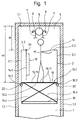
- Fig. 1 is 1 through a shaft walls 1.2 limited elevator shaft in which one Elevator car 2 is movable.
- the shaft head 3 is one Traction sheave 5 arranged with a not shown drive is connected.
- the traction sheave 5 and / or the drive is for example one Wall bracket 6 worn.
- a suspension cable 7 does not have one shown rope course, for example, from a fixed point via a deflection roller of the elevator car 2 or at one Slingshot over two pulleys, further over the Traction sheave 5, further via a deflection roller one represented counterweight and on to another Fixed point.
- a maintenance platform designated 10 is in the Elevator car 2 arranged and is used for the maintenance of Shaft equipment, such as traction sheave 5, Drive, suspension cable 7, guide rails, shaft switch, etc ..
- the maintenance platform 10 For the transport of people and Goods is the maintenance platform 10 as with an interrupted Line shown stowable on a hatch cover 14.1.
- For Maintenance work in elevator shaft 1 is the maintenance platform 10 buildable as shown in Fig. 1.
- the maintenance platform 10 is like a broken line shown in folded form on the hatch cover 14.1 stowable.
- Hatch cover 14.1 around a first pivot point D1 in the Elevator car 2 folded.
- the maintenance platform 10 is now in collapsed form accessible for construction.
- the Cabin walls 2.1 are load-bearing parts of the maintenance platform 10.
- the cross connector 10.3 carry plates 10.11 forming the pedestal 10.1.
- the supports 10.2 are pivotable about second pivot points D2.
- the supports are for the transport of people and goods 10.2 in the position shown with a broken line outside the elevator car 2.
- the handrails can be used as a support for the cross connector 10.3.
- the supports 10.2 shown in Fig. 1 are in this Design variant not necessary, the remaining parts of the Maintenance platform 10 remain the same as explained above.
- a hatch 14 is provided in the roof of the elevator car 2, which can be closed by means of the hatch cover 14.1. How 1 shows the hatch cover 14.1 around the first Pivot D1 foldable, it can also be used as a removable one Hatch cover 14.1.
- the position and size of hatch 14 is chosen so that the hatch 14 is not arranged in the shaft head 3 Shaft equipment such as the traction sheave 5 and / or is towered over by the drive.
- the one shown machine room-less elevator planning offers with your shortened shaft head 3 for the maintenance of the cabin roof from insufficient height H for a proper Crossing (distance between cabin ceiling 2.2 and Shaft ceiling 1.1) of, for example, one meter.
- With the Maintenance platform 10 according to the invention in the shown Working position is for the safety of the Maintenance personnel 17 catered for and required Crossing Ü reached because no longer the distance between determining the cabin ceiling 2.2 and the shaft ceiling 1.1 but the distance between the pedestal 10.1 and the Shaft cover 1.1 and because no shaft equipment in the Shaft head 3 overhangs hatch 14.
Landscapes
- Engineering & Computer Science (AREA)
- Civil Engineering (AREA)
- Mechanical Engineering (AREA)
- Structural Engineering (AREA)
- Cage And Drive Apparatuses For Elevators (AREA)
- Maintenance And Inspection Apparatuses For Elevators (AREA)
- Heat Treatment Of Articles (AREA)
- Lift-Guide Devices, And Elevator Ropes And Cables (AREA)
- Vehicle Cleaning, Maintenance, Repair, Refitting, And Outriggers (AREA)
- Movable Scaffolding (AREA)
- Indicating And Signalling Devices For Elevators (AREA)
- Types And Forms Of Lifts (AREA)
Abstract
Description
- Fig. 1
- eine schematische Darstellung einer auf der obersten Haltestelle stehenden Aufzugskabine mit Wartungsbühne in einem Aufzugsschacht mit verkürztem Schachtkopf.
Claims (7)
- Einrichtung zur Ausführung von Arbeiten in einem Aufzugsschacht (1), in dem eine Aufzugskabine (2) mit Wartungsbühne (10) verfahrbar ist, von der aus die Arbeiten ausführbar sind,
dadurch gekennzeichnet,
dass die Kabinenwände (2.1) tragende Teile der zusammenklappbaren Wartungsbühne (10) mit Podest (10.1) sind, von dem aus die Arbeiten im Aufzugsschacht (1) ausführbar sind. - Einrichtung nach Anspruch 1,
dadurch gekennzeichnet,
dass die Aufzugskabine (2) an Kabinenwänden (2.1) angeordnete Auflager (10.2) aufweist, die die Wartungsbühne (10) mit Podest (10.1) tragen. - Einrichtung nach den Ansprüchen 1 oder 2,
dadurch gekennzeichnet,
dass die Auflager (10.2) für den Aufbau der Wartungsbühne (10) in die Aufzugskabine (2) schwenkbar sind. - Einrichtung nach den Ansprüchen 1 oder 2,
dadurch gekennzeichnet,
dass als Auflager an den Kabinenwänden (2.1) angeordnete Handläufe dienen. - Einrichtung nach den Ansprüchen 1 bis 4,
dadurch gekennzeichnet,
dass die Wartungsbühne (10) an einem Lukendeckel (14.1) verstaubar ist. - Einrichtung nach den vorhergehenden Ansprüchen,
dadurch gekennzeichnet,
dass die Wartungsbühne (10) mit den Auflagern (10.2) verbindhare Querverbinder (10.3) aufweist, die das Podest (10.1) tragen. - Einrichtung nach Anspruch 6,
dadurch gekennzeichnet,
dass zur Stabilisierung der Wartungsbühne (10) diagonal verlaufende Streben (10.4) zwischen den Auflagern (10.2) und einem Kabinenboden (13) angeordnet sind.
Priority Applications (1)
| Application Number | Priority Date | Filing Date | Title |
|---|---|---|---|
| EP00108761A EP1050504B1 (de) | 1999-05-07 | 2000-04-25 | Einrichtung zur Ausführung von Arbeiten in einem Aufzugsschacht |
Applications Claiming Priority (3)
| Application Number | Priority Date | Filing Date | Title |
|---|---|---|---|
| EP99810400 | 1999-05-07 | ||
| EP99810400 | 1999-05-07 | ||
| EP00108761A EP1050504B1 (de) | 1999-05-07 | 2000-04-25 | Einrichtung zur Ausführung von Arbeiten in einem Aufzugsschacht |
Publications (2)
| Publication Number | Publication Date |
|---|---|
| EP1050504A1 true EP1050504A1 (de) | 2000-11-08 |
| EP1050504B1 EP1050504B1 (de) | 2006-06-21 |
Family
ID=8242818
Family Applications (1)
| Application Number | Title | Priority Date | Filing Date |
|---|---|---|---|
| EP00108761A Expired - Lifetime EP1050504B1 (de) | 1999-05-07 | 2000-04-25 | Einrichtung zur Ausführung von Arbeiten in einem Aufzugsschacht |
Country Status (9)
| Country | Link |
|---|---|
| US (1) | US6419052B1 (de) |
| EP (1) | EP1050504B1 (de) |
| JP (1) | JP2000318941A (de) |
| AT (1) | ATE330896T1 (de) |
| CA (1) | CA2307424C (de) |
| DE (1) | DE50013018D1 (de) |
| ES (1) | ES2267430T3 (de) |
| NO (1) | NO320386B1 (de) |
| PT (1) | PT1050504E (de) |
Cited By (4)
| Publication number | Priority date | Publication date | Assignee | Title |
|---|---|---|---|---|
| DE10104351A1 (de) * | 2001-02-01 | 2002-08-22 | Ingenieurgesellschaft Foerder | Aufzug mit auf der Aufzugskabine mitfahrender Antriebseinheit und Steuereinheit |
| FR2845074A1 (fr) * | 2002-10-10 | 2004-04-02 | Otis Elevator Co | Plafond ouvrant de cabine d'ascenseur pour l'intervention sur les equipements fixes dans le tremie |
| WO2016054663A3 (en) * | 2014-09-10 | 2016-06-09 | Eleclip Interior Systems, Llc | Elevator ceiling |
| CN108016974A (zh) * | 2018-01-26 | 2018-05-11 | 苏州沃诺斯精密机械有限公司 | 一种升降电梯框架 |
Families Citing this family (15)
| Publication number | Priority date | Publication date | Assignee | Title |
|---|---|---|---|---|
| JPWO2004058619A1 (ja) * | 2002-12-24 | 2006-04-27 | 三菱電機株式会社 | エレベータ装置 |
| US20050224299A1 (en) * | 2004-04-13 | 2005-10-13 | Soemardjan San A | Elevator recessed car top for refuge area |
| JP2007063021A (ja) * | 2005-08-30 | 2007-03-15 | Inventio Ag | 保守プラットフォームを有するエレベータケージ、およびエレベータ設備の保守のための方法 |
| CH700501B1 (de) * | 2007-09-17 | 2010-09-15 | Henseler H Ag | Liftkabine für reduzierte Liftschachtköpfe. |
| FI20116096L (fi) * | 2011-11-07 | 2013-05-08 | Kone Corp | Nivelöintijärjestely, kattoelementti ja hissi |
| CN107074479B (zh) * | 2014-07-25 | 2019-08-23 | 奥的斯电梯公司 | 从电梯系统的轿厢内部进行电梯系统维护 |
| AT517871B1 (de) * | 2015-10-16 | 2017-12-15 | Norbert Steiner | Aufzugskabine |
| WO2018011458A1 (en) * | 2016-07-15 | 2018-01-18 | Kone Corporation | Elevator arrangement to open the roof of an elevator car |
| EP3309101B1 (de) | 2016-10-17 | 2020-06-03 | Otis Elevator Company | Aufzugskabine, aufzugssystem und verfahren zur überprüfung, wartung und/oder reparatur eines aufzugssystems |
| EP3702309B1 (de) * | 2019-03-01 | 2026-04-29 | Otis Elevator Company | Aufzugskabine mit einer arbeitsbühne |
| EP3760564B1 (de) * | 2019-07-05 | 2023-05-17 | Otis Elevator Company | Aufzugskabine mit arbeitsplattformstabilisierung |
| ES2941919T3 (es) * | 2019-11-26 | 2023-05-26 | Otis Elevator Co | Cabina de ascensor con asistencia mecánica para plataforma de trabajo |
| EP3909897A1 (de) * | 2020-05-12 | 2021-11-17 | KONE Corporation | Aufzugkabine, aufzug und verfahren |
| US11427441B2 (en) | 2020-07-23 | 2022-08-30 | Otis Elevator Company | Elevator car with foldable working platform |
| EP4506291A1 (de) * | 2023-08-10 | 2025-02-12 | Otis Elevator Company | Aufzugskabine mit verstaubarer arbeitsplattform |
Citations (2)
| Publication number | Priority date | Publication date | Assignee | Title |
|---|---|---|---|---|
| JPH0977426A (ja) * | 1995-09-12 | 1997-03-25 | Hitachi Building Syst Co Ltd | ホームエレベータのかご内装置 |
| JPH0986835A (ja) * | 1995-09-28 | 1997-03-31 | Mitsubishi Denki Bill Techno Service Kk | エレベータ乗りかご内椅子兼用手摺 |
Family Cites Families (6)
| Publication number | Priority date | Publication date | Assignee | Title |
|---|---|---|---|---|
| US627257A (en) * | 1899-06-20 | Elevator-cage escape | ||
| JPH02291377A (ja) * | 1989-04-28 | 1990-12-03 | Mitsubishi Electric Corp | エレベータのかご装置 |
| JPH03177284A (ja) * | 1989-12-04 | 1991-08-01 | Mitsubishi Electric Corp | エレベータかご室の非常脱出装置 |
| JPH0597357A (ja) | 1991-10-04 | 1993-04-20 | Mitsubishi Electric Corp | エレベーターかご装置 |
| JPH05147845A (ja) * | 1991-11-29 | 1993-06-15 | Mitsubishi Electric Corp | エレベータの点検装置 |
| JP3177284B2 (ja) | 1992-02-28 | 2001-06-18 | 三洋電機株式会社 | ビデオカメラ回路 |
-
2000
- 2000-04-21 JP JP2000120846A patent/JP2000318941A/ja not_active Withdrawn
- 2000-04-25 PT PT00108761T patent/PT1050504E/pt unknown
- 2000-04-25 DE DE50013018T patent/DE50013018D1/de not_active Expired - Lifetime
- 2000-04-25 ES ES00108761T patent/ES2267430T3/es not_active Expired - Lifetime
- 2000-04-25 EP EP00108761A patent/EP1050504B1/de not_active Expired - Lifetime
- 2000-04-25 AT AT00108761T patent/ATE330896T1/de active
- 2000-04-27 NO NO20002196A patent/NO320386B1/no unknown
- 2000-05-03 CA CA002307424A patent/CA2307424C/en not_active Expired - Fee Related
- 2000-05-04 US US09/564,848 patent/US6419052B1/en not_active Expired - Fee Related
Patent Citations (2)
| Publication number | Priority date | Publication date | Assignee | Title |
|---|---|---|---|---|
| JPH0977426A (ja) * | 1995-09-12 | 1997-03-25 | Hitachi Building Syst Co Ltd | ホームエレベータのかご内装置 |
| JPH0986835A (ja) * | 1995-09-28 | 1997-03-31 | Mitsubishi Denki Bill Techno Service Kk | エレベータ乗りかご内椅子兼用手摺 |
Non-Patent Citations (1)
| Title |
|---|
| PATENT ABSTRACTS OF JAPAN vol. 1997, no. 07 31 July 1997 (1997-07-31) * |
Cited By (4)
| Publication number | Priority date | Publication date | Assignee | Title |
|---|---|---|---|---|
| DE10104351A1 (de) * | 2001-02-01 | 2002-08-22 | Ingenieurgesellschaft Foerder | Aufzug mit auf der Aufzugskabine mitfahrender Antriebseinheit und Steuereinheit |
| FR2845074A1 (fr) * | 2002-10-10 | 2004-04-02 | Otis Elevator Co | Plafond ouvrant de cabine d'ascenseur pour l'intervention sur les equipements fixes dans le tremie |
| WO2016054663A3 (en) * | 2014-09-10 | 2016-06-09 | Eleclip Interior Systems, Llc | Elevator ceiling |
| CN108016974A (zh) * | 2018-01-26 | 2018-05-11 | 苏州沃诺斯精密机械有限公司 | 一种升降电梯框架 |
Also Published As
| Publication number | Publication date |
|---|---|
| DE50013018D1 (de) | 2006-08-03 |
| ES2267430T3 (es) | 2007-03-16 |
| JP2000318941A (ja) | 2000-11-21 |
| NO320386B1 (no) | 2005-11-28 |
| NO20002196D0 (no) | 2000-04-27 |
| CA2307424A1 (en) | 2000-11-07 |
| ATE330896T1 (de) | 2006-07-15 |
| US6419052B1 (en) | 2002-07-16 |
| PT1050504E (pt) | 2006-10-31 |
| CA2307424C (en) | 2008-08-05 |
| EP1050504B1 (de) | 2006-06-21 |
| NO20002196L (no) | 2000-11-08 |
Similar Documents
| Publication | Publication Date | Title |
|---|---|---|
| EP1050504B1 (de) | Einrichtung zur Ausführung von Arbeiten in einem Aufzugsschacht | |
| EP1276692B1 (de) | Einrichtung zur ausführung von arbeiten in einem aufzugsschacht | |
| EP1052212A1 (de) | Einrichtung zur Ausführung von Arbeiten in einem Aufzugsschacht | |
| DE4005997C1 (de) | ||
| DE3149566A1 (de) | Versorgungsfahrzeug mit hubplattform, insbesondere zur versorgung der bordkuechen von grossraumflugzeugen | |
| DE10297157T5 (de) | Sicherheitsvorrichtung für Wartung von Aufzugsystemen vom Dach der Kabine aus | |
| EP1050505B1 (de) | Einrichtung zur Ausführung von Arbeiten in einem Aufzugsschacht | |
| EP1050506B1 (de) | Einrichtung zur Ausführung von Arbeiten in einem Aufzugsschacht | |
| EP1026117B1 (de) | Einrichtung zur Ausführung von Arbeiten in einem Aufzugsschacht | |
| DE10038666C1 (de) | Arbeitsplattform für ein Regallager | |
| DE826341C (de) | Verfahrbarer Baukran | |
| DE2451673A1 (de) | Rettungsgeraet | |
| DE4217333A1 (de) | Hebezeug für Lasten | |
| DE102010010081A1 (de) | Aufzug-Bett | |
| DE1174956B (de) | Fuer Material- und Personenbefoerderung eingerichteter Bauaufzug | |
| DE2114402A1 (de) | Verteilerkran | |
| DE3503836A1 (de) | Teleskoptreppe | |
| DE102004009401A1 (de) | Kabelkran | |
| DE659112C (de) | Ladevorrichtung fuer Foerderwagen mit einer einklappbaren Hebeplatte | |
| DE102008006803B4 (de) | Verfahren zum Beladen eines Frachtraums | |
| DE663900C (de) | Wippkran | |
| DE1807434C3 (de) | Arbeitsbühnen-Vorrichtung für metallurgische Schmelzöfen, insbesondere für Stahlwerkskonverter | |
| DE3841467A1 (de) | Transportfahrzeug fuer personen und gueter von und zu luftfahrzeugen | |
| DE868657C (de) | Fahrbarer Drehkran | |
| DE73543C (de) | Verschlufsvorrichtung für Einsteigeöffnungen mit parallel zu sich selbst verschiebbarer Verschlussklappe |
Legal Events
| Date | Code | Title | Description |
|---|---|---|---|
| PUAI | Public reference made under article 153(3) epc to a published international application that has entered the european phase |
Free format text: ORIGINAL CODE: 0009012 |
|
| AK | Designated contracting states |
Kind code of ref document: A1 Designated state(s): AT BE CH CY DE DK ES FI FR GB GR IE IT LI LU MC NL PT SE |
|
| AX | Request for extension of the european patent |
Free format text: AL;LT;LV;MK;RO;SI |
|
| 17P | Request for examination filed |
Effective date: 20010419 |
|
| AKX | Designation fees paid |
Free format text: AT BE CH CY DE DK ES FI FR GB GR IE IT LI LU MC NL PT SE |
|
| 17Q | First examination report despatched |
Effective date: 20030410 |
|
| GRAP | Despatch of communication of intention to grant a patent |
Free format text: ORIGINAL CODE: EPIDOSNIGR1 |
|
| GRAS | Grant fee paid |
Free format text: ORIGINAL CODE: EPIDOSNIGR3 |
|
| GRAA | (expected) grant |
Free format text: ORIGINAL CODE: 0009210 |
|
| AK | Designated contracting states |
Kind code of ref document: B1 Designated state(s): AT BE CH CY DE DK ES FI FR GB GR IE IT LI LU MC NL PT SE |
|
| PG25 | Lapsed in a contracting state [announced via postgrant information from national office to epo] |
Ref country code: IT Free format text: LAPSE BECAUSE OF FAILURE TO SUBMIT A TRANSLATION OF THE DESCRIPTION OR TO PAY THE FEE WITHIN THE PRESCRIBED TIME-LIMIT;WARNING: LAPSES OF ITALIAN PATENTS WITH EFFECTIVE DATE BEFORE 2007 MAY HAVE OCCURRED AT ANY TIME BEFORE 2007. THE CORRECT EFFECTIVE DATE MAY BE DIFFERENT FROM THE ONE RECORDED. Effective date: 20060621 |
|
| REG | Reference to a national code |
Ref country code: GB Ref legal event code: FG4D Free format text: NOT ENGLISH |
|
| REG | Reference to a national code |
Ref country code: CH Ref legal event code: EP |
|
| REG | Reference to a national code |
Ref country code: IE Ref legal event code: FG4D Free format text: LANGUAGE OF EP DOCUMENT: GERMAN |
|
| REF | Corresponds to: |
Ref document number: 50013018 Country of ref document: DE Date of ref document: 20060803 Kind code of ref document: P |
|
| GBT | Gb: translation of ep patent filed (gb section 77(6)(a)/1977) |
Effective date: 20060731 |
|
| PG25 | Lapsed in a contracting state [announced via postgrant information from national office to epo] |
Ref country code: DK Free format text: LAPSE BECAUSE OF FAILURE TO SUBMIT A TRANSLATION OF THE DESCRIPTION OR TO PAY THE FEE WITHIN THE PRESCRIBED TIME-LIMIT Effective date: 20060921 |
|
| REG | Reference to a national code |
Ref country code: GR Ref legal event code: EP Ref document number: 20060402624 Country of ref document: GR |
|
| REG | Reference to a national code |
Ref country code: SE Ref legal event code: TRGR |
|
| REG | Reference to a national code |
Ref country code: PT Ref legal event code: SC4A Effective date: 20060901 |
|
| ET | Fr: translation filed | ||
| REG | Reference to a national code |
Ref country code: ES Ref legal event code: FG2A Ref document number: 2267430 Country of ref document: ES Kind code of ref document: T3 |
|
| PLBE | No opposition filed within time limit |
Free format text: ORIGINAL CODE: 0009261 |
|
| STAA | Information on the status of an ep patent application or granted ep patent |
Free format text: STATUS: NO OPPOSITION FILED WITHIN TIME LIMIT |
|
| 26N | No opposition filed |
Effective date: 20070322 |
|
| PG25 | Lapsed in a contracting state [announced via postgrant information from national office to epo] |
Ref country code: IE Free format text: LAPSE BECAUSE OF NON-PAYMENT OF DUE FEES Effective date: 20070425 |
|
| PGFP | Annual fee paid to national office [announced via postgrant information from national office to epo] |
Ref country code: PT Payment date: 20080324 Year of fee payment: 9 |
|
| PGFP | Annual fee paid to national office [announced via postgrant information from national office to epo] |
Ref country code: BE Payment date: 20080522 Year of fee payment: 9 |
|
| PGFP | Annual fee paid to national office [announced via postgrant information from national office to epo] |
Ref country code: SE Payment date: 20080414 Year of fee payment: 9 |
|
| PG25 | Lapsed in a contracting state [announced via postgrant information from national office to epo] |
Ref country code: MC Free format text: LAPSE BECAUSE OF NON-PAYMENT OF DUE FEES Effective date: 20070430 |
|
| PG25 | Lapsed in a contracting state [announced via postgrant information from national office to epo] |
Ref country code: LU Free format text: LAPSE BECAUSE OF NON-PAYMENT OF DUE FEES Effective date: 20070425 Ref country code: CY Free format text: LAPSE BECAUSE OF FAILURE TO SUBMIT A TRANSLATION OF THE DESCRIPTION OR TO PAY THE FEE WITHIN THE PRESCRIBED TIME-LIMIT Effective date: 20060621 |
|
| BERE | Be: lapsed |
Owner name: *INVENTIO A.G. Effective date: 20090430 |
|
| REG | Reference to a national code |
Ref country code: PT Ref legal event code: MM4A Free format text: LAPSE DUE TO NON-PAYMENT OF FEES Effective date: 20091026 |
|
| EUG | Se: european patent has lapsed | ||
| PG25 | Lapsed in a contracting state [announced via postgrant information from national office to epo] |
Ref country code: PT Free format text: LAPSE BECAUSE OF NON-PAYMENT OF DUE FEES Effective date: 20091026 |
|
| PG25 | Lapsed in a contracting state [announced via postgrant information from national office to epo] |
Ref country code: BE Free format text: LAPSE BECAUSE OF NON-PAYMENT OF DUE FEES Effective date: 20090430 |
|
| PG25 | Lapsed in a contracting state [announced via postgrant information from national office to epo] |
Ref country code: SE Free format text: LAPSE BECAUSE OF NON-PAYMENT OF DUE FEES Effective date: 20090426 |
|
| PGFP | Annual fee paid to national office [announced via postgrant information from national office to epo] |
Ref country code: GR Payment date: 20110418 Year of fee payment: 12 Ref country code: FR Payment date: 20110510 Year of fee payment: 12 Ref country code: DE Payment date: 20110421 Year of fee payment: 12 Ref country code: ES Payment date: 20110426 Year of fee payment: 12 |
|
| PGFP | Annual fee paid to national office [announced via postgrant information from national office to epo] |
Ref country code: NL Payment date: 20110426 Year of fee payment: 12 Ref country code: FI Payment date: 20110414 Year of fee payment: 12 Ref country code: AT Payment date: 20110414 Year of fee payment: 12 Ref country code: GB Payment date: 20110421 Year of fee payment: 12 |
|
| PGFP | Annual fee paid to national office [announced via postgrant information from national office to epo] |
Ref country code: IT Payment date: 20110421 Year of fee payment: 12 |
|
| PGFP | Annual fee paid to national office [announced via postgrant information from national office to epo] |
Ref country code: CH Payment date: 20110711 Year of fee payment: 12 |
|
| REG | Reference to a national code |
Ref country code: NL Ref legal event code: V1 Effective date: 20121101 |
|
| REG | Reference to a national code |
Ref country code: CH Ref legal event code: PL |
|
| REG | Reference to a national code |
Ref country code: AT Ref legal event code: MM01 Ref document number: 330896 Country of ref document: AT Kind code of ref document: T Effective date: 20120425 |
|
| GBPC | Gb: european patent ceased through non-payment of renewal fee |
Effective date: 20120425 |
|
| REG | Reference to a national code |
Ref country code: FR Ref legal event code: ST Effective date: 20121228 |
|
| REG | Reference to a national code |
Ref country code: GR Ref legal event code: ML Ref document number: 20060402624 Country of ref document: GR Effective date: 20121102 |
|
| PG25 | Lapsed in a contracting state [announced via postgrant information from national office to epo] |
Ref country code: LI Free format text: LAPSE BECAUSE OF NON-PAYMENT OF DUE FEES Effective date: 20120430 Ref country code: GB Free format text: LAPSE BECAUSE OF NON-PAYMENT OF DUE FEES Effective date: 20120425 Ref country code: CH Free format text: LAPSE BECAUSE OF NON-PAYMENT OF DUE FEES Effective date: 20120430 Ref country code: AT Free format text: LAPSE BECAUSE OF NON-PAYMENT OF DUE FEES Effective date: 20120425 Ref country code: FI Free format text: LAPSE BECAUSE OF NON-PAYMENT OF DUE FEES Effective date: 20120425 |
|
| REG | Reference to a national code |
Ref country code: DE Ref legal event code: R119 Ref document number: 50013018 Country of ref document: DE Effective date: 20121101 |
|
| PG25 | Lapsed in a contracting state [announced via postgrant information from national office to epo] |
Ref country code: GR Free format text: LAPSE BECAUSE OF NON-PAYMENT OF DUE FEES Effective date: 20121102 Ref country code: FR Free format text: LAPSE BECAUSE OF NON-PAYMENT OF DUE FEES Effective date: 20120430 Ref country code: IT Free format text: LAPSE BECAUSE OF NON-PAYMENT OF DUE FEES Effective date: 20120425 |
|
| PG25 | Lapsed in a contracting state [announced via postgrant information from national office to epo] |
Ref country code: NL Free format text: LAPSE BECAUSE OF NON-PAYMENT OF DUE FEES Effective date: 20121101 |
|
| REG | Reference to a national code |
Ref country code: ES Ref legal event code: FD2A Effective date: 20131030 |
|
| PG25 | Lapsed in a contracting state [announced via postgrant information from national office to epo] |
Ref country code: ES Free format text: LAPSE BECAUSE OF NON-PAYMENT OF DUE FEES Effective date: 20120426 |
|
| PG25 | Lapsed in a contracting state [announced via postgrant information from national office to epo] |
Ref country code: DE Free format text: LAPSE BECAUSE OF NON-PAYMENT OF DUE FEES Effective date: 20121101 |