EP1004448A2 - Drucker mit zugeordneter Tintenkassette - Google Patents
Drucker mit zugeordneter Tintenkassette Download PDFInfo
- Publication number
- EP1004448A2 EP1004448A2 EP99309442A EP99309442A EP1004448A2 EP 1004448 A2 EP1004448 A2 EP 1004448A2 EP 99309442 A EP99309442 A EP 99309442A EP 99309442 A EP99309442 A EP 99309442A EP 1004448 A2 EP1004448 A2 EP 1004448A2
- Authority
- EP
- European Patent Office
- Prior art keywords
- printer
- ink
- cartridge
- information
- volatile memory
- Prior art date
- Legal status (The legal status is an assumption and is not a legal conclusion. Google has not performed a legal analysis and makes no representation as to the accuracy of the status listed.)
- Granted
Links
- 239000000976 ink Substances 0.000 claims abstract description 544
- 230000015654 memory Effects 0.000 claims abstract description 194
- 238000003860 storage Methods 0.000 claims abstract description 149
- 238000000034 method Methods 0.000 claims description 49
- 230000005540 biological transmission Effects 0.000 claims description 25
- 238000006243 chemical reaction Methods 0.000 claims description 17
- 230000004044 response Effects 0.000 claims description 17
- 238000004140 cleaning Methods 0.000 claims description 15
- 238000004519 manufacturing process Methods 0.000 abstract description 18
- 238000005549 size reduction Methods 0.000 abstract description 2
- 238000012545 processing Methods 0.000 description 41
- 238000012546 transfer Methods 0.000 description 25
- 230000008569 process Effects 0.000 description 23
- 238000011010 flushing procedure Methods 0.000 description 10
- 230000007246 mechanism Effects 0.000 description 8
- 230000009471 action Effects 0.000 description 6
- 238000004364 calculation method Methods 0.000 description 6
- 238000010586 diagram Methods 0.000 description 6
- 238000004891 communication Methods 0.000 description 5
- 230000006870 function Effects 0.000 description 5
- 230000004048 modification Effects 0.000 description 5
- 238000012986 modification Methods 0.000 description 5
- 230000001186 cumulative effect Effects 0.000 description 4
- 239000002904 solvent Substances 0.000 description 4
- 230000008901 benefit Effects 0.000 description 3
- 239000003086 colorant Substances 0.000 description 3
- 230000033001 locomotion Effects 0.000 description 3
- 239000000049 pigment Substances 0.000 description 3
- 230000004913 activation Effects 0.000 description 2
- 238000003491 array Methods 0.000 description 2
- 230000007423 decrease Effects 0.000 description 2
- 230000000694 effects Effects 0.000 description 2
- 238000011068 loading method Methods 0.000 description 2
- 230000002093 peripheral effect Effects 0.000 description 2
- 230000005856 abnormality Effects 0.000 description 1
- 230000004075 alteration Effects 0.000 description 1
- 238000004458 analytical method Methods 0.000 description 1
- 230000015572 biosynthetic process Effects 0.000 description 1
- 239000003990 capacitor Substances 0.000 description 1
- 238000012937 correction Methods 0.000 description 1
- 239000000428 dust Substances 0.000 description 1
- 230000002708 enhancing effect Effects 0.000 description 1
- 230000009545 invasion Effects 0.000 description 1
- 239000007788 liquid Substances 0.000 description 1
- 230000013011 mating Effects 0.000 description 1
- 238000002156 mixing Methods 0.000 description 1
- 230000037361 pathway Effects 0.000 description 1
- 238000002360 preparation method Methods 0.000 description 1
- 230000008707 rearrangement Effects 0.000 description 1
- 229920003002 synthetic resin Polymers 0.000 description 1
- 239000000057 synthetic resin Substances 0.000 description 1
- 238000009834 vaporization Methods 0.000 description 1
- 230000008016 vaporization Effects 0.000 description 1
Images


Classifications
-
- B—PERFORMING OPERATIONS; TRANSPORTING
- B41—PRINTING; LINING MACHINES; TYPEWRITERS; STAMPS
- B41J—TYPEWRITERS; SELECTIVE PRINTING MECHANISMS, i.e. MECHANISMS PRINTING OTHERWISE THAN FROM A FORME; CORRECTION OF TYPOGRAPHICAL ERRORS
- B41J2/00—Typewriters or selective printing mechanisms characterised by the printing or marking process for which they are designed
- B41J2/005—Typewriters or selective printing mechanisms characterised by the printing or marking process for which they are designed characterised by bringing liquid or particles selectively into contact with a printing material
- B41J2/01—Ink jet
- B41J2/17—Ink jet characterised by ink handling
-
- G—PHYSICS
- G06—COMPUTING; CALCULATING OR COUNTING
- G06K—GRAPHICAL DATA READING; PRESENTATION OF DATA; RECORD CARRIERS; HANDLING RECORD CARRIERS
- G06K15/00—Arrangements for producing a permanent visual presentation of the output data, e.g. computer output printers
- G06K15/02—Arrangements for producing a permanent visual presentation of the output data, e.g. computer output printers using printers
- G06K15/10—Arrangements for producing a permanent visual presentation of the output data, e.g. computer output printers using printers by matrix printers
- G06K15/102—Arrangements for producing a permanent visual presentation of the output data, e.g. computer output printers using printers by matrix printers using ink jet print heads
-
- B—PERFORMING OPERATIONS; TRANSPORTING
- B41—PRINTING; LINING MACHINES; TYPEWRITERS; STAMPS
- B41J—TYPEWRITERS; SELECTIVE PRINTING MECHANISMS, i.e. MECHANISMS PRINTING OTHERWISE THAN FROM A FORME; CORRECTION OF TYPOGRAPHICAL ERRORS
- B41J2/00—Typewriters or selective printing mechanisms characterised by the printing or marking process for which they are designed
- B41J2/005—Typewriters or selective printing mechanisms characterised by the printing or marking process for which they are designed characterised by bringing liquid or particles selectively into contact with a printing material
- B41J2/01—Ink jet
- B41J2/17—Ink jet characterised by ink handling
- B41J2/175—Ink supply systems ; Circuit parts therefor
- B41J2/17503—Ink cartridges
- B41J2/17543—Cartridge presence detection or type identification
- B41J2/17546—Cartridge presence detection or type identification electronically
-
- B—PERFORMING OPERATIONS; TRANSPORTING
- B41—PRINTING; LINING MACHINES; TYPEWRITERS; STAMPS
- B41J—TYPEWRITERS; SELECTIVE PRINTING MECHANISMS, i.e. MECHANISMS PRINTING OTHERWISE THAN FROM A FORME; CORRECTION OF TYPOGRAPHICAL ERRORS
- B41J2/00—Typewriters or selective printing mechanisms characterised by the printing or marking process for which they are designed
- B41J2/005—Typewriters or selective printing mechanisms characterised by the printing or marking process for which they are designed characterised by bringing liquid or particles selectively into contact with a printing material
- B41J2/01—Ink jet
- B41J2/17—Ink jet characterised by ink handling
- B41J2/175—Ink supply systems ; Circuit parts therefor
- B41J2/17566—Ink level or ink residue control
-
- B—PERFORMING OPERATIONS; TRANSPORTING
- B41—PRINTING; LINING MACHINES; TYPEWRITERS; STAMPS
- B41J—TYPEWRITERS; SELECTIVE PRINTING MECHANISMS, i.e. MECHANISMS PRINTING OTHERWISE THAN FROM A FORME; CORRECTION OF TYPOGRAPHICAL ERRORS
- B41J2/00—Typewriters or selective printing mechanisms characterised by the printing or marking process for which they are designed
- B41J2/005—Typewriters or selective printing mechanisms characterised by the printing or marking process for which they are designed characterised by bringing liquid or particles selectively into contact with a printing material
- B41J2/01—Ink jet
- B41J2/135—Nozzles
- B41J2/165—Prevention or detection of nozzle clogging, e.g. cleaning, capping or moistening for nozzles
- B41J2/16517—Cleaning of print head nozzles
- B41J2/1652—Cleaning of print head nozzles by driving a fluid through the nozzles to the outside thereof, e.g. by applying pressure to the inside or vacuum at the outside of the print head
Definitions
- the present invention relates to a printer with an ink cartridge attached thereto that carries out printing by the unit of dots, as well as to an ink cartridge detachably attached to a main body of the printer. More specifically the invention pertains to a technique of storing information into the ink cartridge.
- the printing apparatus like the ink jet printer and the ink jet plotter mainly includes an ink cartridge, in which one or plural inks are kept, and a printer main body with a print head to carry out actual printing operations on a printing medium.
- the print head transfers ink fed from the ink cartridge onto the printing medium, such as printing paper, so as to implement printing on the printing medium.
- the ink cartridge is designed to be detachably attached to the printer main body.
- a new ink cartridge has a predetermined quantity of ink kept therein. When the ink kept in an ink cartridge runs out, the ink cartridge is replaced with a new one.
- Such a printing apparatus is arranged to cause the printer main body to calculate the remaining quantity of ink in the ink cartridge based on the amount of ink transferred from the print head and to inform the user of a state of running out of the ink, in order to prevent the printing procedure from being interrupted by the out-of-ink.
- the data on the remaining quantities of inks are generally stored only in the printer main body or in a printer driver that controls the printer. In the event that a first ink cartridge is replaced with a second ink cartridge in the course of the printing operation, the information relating to the first ink cartridge, such as the data on the remaining quantities of inks, are thus lost or made wrong.
- One proposed technique to solve this problem utilizes a non-volatile memory provided in the ink cartridge and causes the required data, for example, the data on the remaining quantities of inks, to be written from the printer main body into the non-volatile memory (for example, JAPANESE PATENT LAID-OPEN GAZETTE No. 62-184856).
- this technique ensures the storage of the data on the remaining quantities of inks.
- the ink cartridge attached to the printer is expendable.
- a non-volatile memory generally used in the printer for example, a large-sized, expensive non-volatile memory having a relatively large storage capacity of several kilobytes and more than ten terminals, is not applicable for the ink cartridge.
- Using such a non-volatile memory makes the ink cartridge undesirably bulky and increases the manufacturing cost of the expendable ink cartridge, which is abandoned after the ink kept in the ink cartridge runs out.
- One proposed technique accordingly applies a small-sized special non-volatile memory having a relatively small storage capacity for the ink cartridge.
- the non-volatile memory with only several terminals adopts a specific format of addressing, which is different from the format of addressing adopted in the general non-volatile memories. This accordingly arises another problem of difficulty in handling.
- the computer that controls the writing operation of data may carry out conversion of the format of addressing.
- the computer that controls the writing operation of data may carry out conversion of the format of addressing.
- an ink cartridge having an ink reservoir, in which a plurality of different inks are kept, and holding required pieces of information, for example, pieces of information on the amounts of ink consumption, independently with regard to the respective inks there are relatively long data lengths to be written and the address conversion requires an undesirably long time.
- Such a disadvantage is not negligible since it may cause all the data to be not rewritten when no sufficient time period is provided for the address conversion, for example, at the time of forcible cut-off of power supply.
- Such printing apparatus includes an ink jet-type printing apparatus that uses ink obtained by mixing or dissolving a pigment or a dye with or in a solvent and transfers ink droplets in the liquid state to implement printing, a printing apparatus that uses an ink cartridge with an ink toner accommodated therein, and a thermal transfer-type printing apparatus.
- the object of the present invention is thus to provide a technique that is applicable to a printer and a cartridge attached thereto and enables information relating to the cartridge, such as pieces of information on remaining quantities of inks or toners, to be adequately processed, while not increasing the manufacturing cost of the cartridge.
- At least part of the above and the other related objects is actualized by a first printer, to which a cartridge is detachably attached, wherein the cartridge keeps ink therein and has a rewritable non-volatile memory.
- the first printer causes the ink kept in the cartridge to be transferred from a print head mounted on the printer to a printing medium, thereby implementing a printing operation.
- the first printer includes: a printer memory that stores information relating to the ink kept in the cartridge into a predetermined area thereof in a predetermined format of addressing, which is different from a specific format of addressing adopted in the non-volatile memory; a memory writing unit that reads the information relating to the ink kept in the cartridge from the predetermined area and writes the read-out information into a specific area of the non-volatile memory, which corresponds to the predetermined area of the printer memory; and an address decoder that converts a storage format of addressing of the information relating to the ink from the predetermined format of addressing into the specific format of addressing when the memory writing unit writes the information.
- the present invention is also directed to a first method that corresponds to the first printer discussed above.
- the present invention thus provides a first method of writing information relating to ink kept in a cartridge into a rewritable non-volatile memory incorporated in the cartridge, which is detachably attached to a printer, wherein the printer causes the ink kept in the cartridge to be transferred from a print head mounted on the printer to a printing medium, thereby implementing a printing operation.
- the first method includes the steps of: storing the information relating to the ink kept in the cartridge into a predetermined area of a printer memory incorporated in the printer in a predetermined format of addressing, which is different from a specific format of addressing adopted in the non-volatile memory; reading the information relating to the ink kept in the cartridge from the predetermined area; converting a storage format of addressing of the information relating to the ink from the predetermined format of addressing into the specific format of addressing; and writing the information in the converted specific format of addressing into a specific area of the non-volatile memory, which corresponds to the predetermined area of the printer memory.
- the information relating to the ink kept in the cartridge is stored in different formats of addressing in the printer memory incorporated in the printer and in the non-volatile memory incorporated in the cartridge.
- the address decoder converts the storage format of addressing when the information is written into the non-volatile memory of the cartridge. This arrangement enables the information relating to the ink to be readily written into the non-volatile memory of the cartridge, even when the format of addressing adopted in the non-volatile memory is different from that adopted in the printer memory.
- the address decoder may also be disposed on the carriage. This arrangement shortens the distance between the address decoder and the cartridge. This is especially advantageous when there is a difficulty in extending the signal lines because of the specific format of addressing adopted in the non-volatile memory of the cartridge.
- the present invention is further directed to a first cartridge that corresponds to the first printer discussed above.
- the present invention accordingly provides a first cartridge that keeps ink therein and is detachably attached to a printer with a print head, wherein the printer causes the ink kept in the cartridge to be transferred from the print head to a printing medium by a unit of dot, thereby implementing a printing operation.
- the first cartridge includes: a rewritable non-volatile memory; an input unit that receives information relating to ink kept in the cartridge, which has been stored in a predetermined format of addressing in a predetermined area of a printer memory incorporated in the printer, in a specific format of addressing that is different from the predetermined format of addressing; and a writing controller that writes the information into the non-volatile memory in the specific format of addressing received by the input unit.
- the non-volatile memory of the cartridge carries out transmission of data by serial access, and the information is written into the non-volatile memory synchronously with a clock for addressing.
- the non-volatile memory of the serial access type generally has a reduced number of terminals and is small in size, thereby contributing to the size reduction of the whole ink cartridge.
- the information written into the non-volatile memory is, for example, a piece of information relating to the quantity of ink in the cartridge.
- the piece of information relating to the quantity of ink may regard a remaining quantity of ink or an amount of ink consumption with respect to the cartridge.
- a plurality of different inks are kept in the cartridge, and the address decoder carries out the conversion of the storage format of addressing corresponding to a plurality of areas provided for the respective inks in the non-volatile memory.
- this arrangement facilitates the storage of information with regard to the respective color inks.
- the same principle is applicable to another cartridge, in which at least five different inks are kept.
- the storage capacity of not greater than 2 bytes is allocated to store a piece of information relating to the quantity of each ink.
- the allocation of the storage capacity of approximately 2 bytes to each ink enables the data to be written into the non-volatile memory of the cartridge within a short time period.
- the non-volatile memory of the cartridge has two information storage areas, in order to enhance the reliability of the stored information.
- the address decoder alternately specifies one of two different addresses every time a requirement of writing information, which has been stored in one area of the printer memory, into the non-volatile memory is output. This arrangement causes the address decoder to specify the addresses and thereby reduces the loading to the printer main body.
- the information may be written into the non-volatile memory of the cartridge after at least one of a timing when a power-off instruction is given to turn off a power source of the printer, a timing when power supply to the printer is cut off, and a timing when a replacement instruction is given to replace the cartridge.
- the address decoder carries out the conversion of the storage format of addressing and writes the information having the converted format into the non-volatile memory after at least one of the above timings. Writing the information into the non-volatile memory of the cartridge at the above timings enables the reliability of information to be kept at a sufficient level. In the case where the cartridge is detached from the printer, this arrangement enables the latest data to be stored in the non-volatile memory of the cartridge.
- a cleaning operation is generally carried out in an ink jet printer, in order to prevent nozzles on the print head from being clogged.
- the cleaning operation consumes a preset amount of ink. It is accordingly desirable to update the information relating to the quantity of ink after each cleaning operation.
- a programmable ROM that is erasable electrically, a flash ROM, or a ferroelectric memory may be applied for the non-volatile memory of the cartridge.
- the present invention is also directed to a second printer, to which a cartridge is detachably attached, wherein the ink cartridge keeps ink therein and has a rewritable non-volatile memory.
- the second printer causes the ink kept in the cartridge to be transferred from a plurality of dot-forming elements, which are formed on a print head mounted on the printer, to a printing medium by a unit of dot, thereby implementing a printing operation.
- the second printer includes: a printer memory that stores information relating to the ink kept in the cartridge into a predetermined area thereof; a data registration unit that is disposed on a carriage, which has the print head mounted thereon and moves forward and backward relative to the printing medium, and temporarily registers therein the information relating to the ink, which is read from the predetermined area of the printer memory; and a memory writing unit that writes the information temporarily registered in the data registration unit into a specific area of the non-volatile memory, which corresponds to the predetermined area of the printer memory.
- the present invention is also directed to a second method that corresponds to the second printer discussed above.
- the present invention thus provides a second method of writing information relating to ink kept in a cartridge into a rewritable non-volatile memory incorporated in the ink cartridge, which is detachably attached to a printer, wherein the printer causes the ink kept in the cartridge to be transferred from a plurality of dot-forming elements, which are formed on a print head mounted on the printer, to a printing medium by a unit of dot, thereby implementing a printing operation.
- the second method includes the steps of: storing the information relating to the ink kept in the cartridge into a predetermined area of a printer memory incorporated in the printer; temporarily storing the information relating to the ink, which is read from the predetermined area of the printer memory, into a temporary memory that is disposed on a carriage, which has the print head mounted thereon and moves forward and backward relative to the printing medium; and writing the information temporarily stored in the temporary memory into a specific area of the non-volatile memory, which corresponds to the predetermined area of the printer memory.
- the present invention is further directed to a second cartridge that corresponds to the second printer discussed above.
- the present invention accordingly provides a second cartridge that keeps ink therein and is detachably attached to a carriage set on a printer, wherein the printer has a plurality of dot-forming elements formed on a print head mounted on the carriage that moves forward and backward relative to a printing medium.
- the printer causes the ink kept in the cartridge to be transferred from the plurality of dot-forming elements on the print head to the printing medium by a unit of dot, thereby implementing a printing operation.
- the second cartridge includes: a rewritable non-volatile memory; an input unit that receives information relating to ink kept in the cartridge, which has been stored in a predetermined format of addressing in a temporary memory mounted on the carriage for temporarily storing information, in a specific format of addressing that is different from the predetermined format of addressing; and a writing controller that writes the information into the non-volatile memory in the specific format of addressing received by the input unit.
- the information relating to the ink kept in the cartridge is stored in a predetermined area of the printer memory.
- the information read from the predetermined area of the printer memory is temporarily registered in the temporary memory on the carriage and eventually written into the non-volatile memory of the cartridge. This arrangement does not require the time-consuming process of reading the respective pieces of information from the printer memory in response to each demand, but facilitates the writing operation of data into the non-volatile memory of the cartridge.
- the information read from the printer memory may be registered into the temporary memory by utilizing the signal line, through which data corresponding to a driving signal to the dot-forming elements are output to the dot-forming elements. This simplifies the configuration of the storage process.
- a common hardware configuration may be applicable for output of data to the dot-forming elements and for output of information to the non-volatile memory.
- one desirable structure has a mechanism of selecting either one of the output of data to the dot-forming elements and the output of information to the non-volatile memory.
- One concrete example of such structure cuts off the power supply to the non-volatile memory in the case of the output of data corresponding to a driving signal to the dot-forming elements.
- the information relating to the quantity of ink may regard a remaining quantity of ink or an amount of ink consumption with respect to the cartridge.
- the non-volatile memory may be a memory that carries out transmission of data by serial access, for example, a programmable ROM that is erasable electrically, a flash ROM, or a ferroelectric memory.
- the structure of incorporating the non-volatile memory in the ink cartridge is applicable to any type of the cartridge.
- the non-volatile memory is provided in both the black ink cartridge and the color ink cartridge, and required pieces of information are written into the respective non-volatile memories.
- the configuration that provides a non-volatile memory for each cartridge enables the data on the quantity of ink with regard to each cartridge to be processed independently.
- the principle of the present invention is also applicable to a printer, to which only a black ink cartridge or a color ink cartridge is detachably attached.
- Fig. 1 is a perspective view illustrating the structure of a main part of an ink jet printer 1 in one embodiment according to the present invention.
- the printer 1 of the embodiment is used in connection with a computer PC, to which a scanner SC is also connected.
- the computer PC reads and executes an operating system and predetermined programs to function, in combination with the printer 1, as a printing apparatus.
- the computer PC executes an application program on a specific operating system, carries out processing of an input image, for example, read from the scanner SC, and displays a processed image on a CRT display MT.
- a printer driver incorporated in the operating system is activated to transfer processed image data to the printer 1.
- a CD drive (not shown) that reads a recording medium, such as a CD-ROM, and other non-illustrated drives are mounted on the computer PC.
- the printer driver converts original color image data, which are input from the scanner SC and subjected to the required image processing, to color image data printable by the printer 1 in response to the printing instruction, and outputs the converted color image data to the printer 1.
- the original color image data consists of three color components, that is, red (R), green (G), and blue (B).
- the converted color image data printable by and output to the printer 1 consists of six color components, that is, black (K), cyan (C), light cyan (LC), magenta (M), light magenta (LM), and yellow (Y).
- the printable color image data are further subjected to binary processing, which specifies the on-off state of ink dots.
- the printer 1 has a print controller 40 that is in charge of control procedures and a print engine 5 that actually performs ejection of ink.
- the print controller 40 and the print engine 5 are incorporated in a printer main body 100.
- the print engine 5 included in the printer main body 100 has a print head 10, a sheet feed mechanism 11, and a carriage mechanism 12.
- the print head 10 is integrally formed with a cartridge attachment unit 18 to construct a carriage 101.
- the print head 10, which is an ink jet type, is mounted on a specific face of the carriage 101 that faces a sheet of printing paper 105, that is, a lower face of the carriage 101 in this embodiment.
- the carriage mechanism 12 includes a carriage motor 103 and a timing belt 102.
- the carriage motor 103 drives the carriage 101 via the timing belt 102.
- the carriage 101 is guided by a guide member 104 and moves forward and backward along a width of the printing paper 105 by means of normal and reverse rotations of the carriage motor 103.
- the sheet feed mechanism 11 that feeds the printing paper 105 includes a sheet feed roller 106 and a sheet feed motor 116.
- a black ink cartridge 107K and a color ink cartridge 107F, which will be described later, are detachably attached to the cartridge attachment unit 18 of the carriage 101.
- the print head 10 receives supplies of inks fed from these ink cartridges 107K and 107F and ejects ink droplets against the printing paper 105 with a movement of the carriage 101, so as to create dots and print a picture image or letters on the printing paper 105.
- Each of the ink cartridges 107K and 107F has a cavity therein for keeping ink, which is prepared by dissolving or dispersing a dye or a pigment in a solvent.
- the cavity for keeping ink therein is generally referred to as an ink chamber.
- the black ink cartridge 107K has an ink chamber 117K, in which black ink (K) is kept.
- the color ink cartridge 107F has a plurality of ink chambers 107C, 107LC, 107M, 107LM, and 107Y, which are formed separately.
- the FFC 300 that connects the parallel input-output interface 49 of the print controller 40 with the carriage 101 has five signal lines. Namely data are transferred through only these five signal lines from the print controller 40 to the print head 10 mounted on the carriage 101 and to the storage elements 80 incorporated in the ink cartridges 107K and 107F set on the carriage 101.
- the control board 205 is connected with the print controller 40 via the FFC 300.
- a transfer controller 220, a control IC 200, and a RAM 210 are mounted on the control board 205.
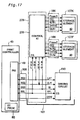
- Fig. 5 shows the detailed structure of the control board 205 on the carriage 101 and the peripheral elements. As shown in Fig. 5, the transfer controller 220 on the control board 205 controls data transmission between the control IC 200 and the print controller 40 and output of data from the print controller 40 to a driving circuit 230, using four signals SG1 through SG4 and a selection control signal SSL received via the FFC 300.
- the transfer controller 220 selects either the control IC 200 or the driving circuit 230 as the destination of data transmission from and to the parallel input-output interface 49 of the print controller 40 via the FFC 300.
- the four signals SG1 through SG4 connecting with the parallel input-output interface 49 are output to the driving circuit 230 as the driving signal COM, a latch signal LAT, a clock signal CLK, and recording data S1, in the case where the selection control signal SSL is at the high level.
- the four signals SG1 through SG4 are connected with the control IC 200 as a receiving signal RxD, a transmitting signal TxD, a power down signal NMI, and a selection signal SEL.
- the print controller 40 When the selection control signal SSL is at the high level, the print controller 40 enables signals for generating an image to be output from the parallel input-output interface 49 to the driving circuit 230 via the transfer controller 220.
- the print controller 40 causes ink droplets to be ejected from the respective nozzles on the print head 10, so as to implement printing, while driving the sheet feed mechanism 11 and the carriage mechanism 12 of the print engine 5. This process is described more in detail.
- the driving circuit 230 includes a shift register circuit 13 that converts serially transferred data to parallel data corresponding to the respective nozzles, a latch circuit 14 that holds the output of the shift register circuit 13 for a predetermined time period, a level shifter circuit 15 that amplifies the output of the latch circuit 14 to a voltage level of several tens volts, and a nozzle selection circuit (analog switch) 16 that is operated in response to the output of the level shifter circuit 15.
- the driving signal COM output from the driving signal generator circuit 48 connects with the input of the nozzle selection circuit 16.
- the output of the nozzle selection circuit 16 connects with a plurality of piezoelectric vibrators 17 provided on the print head 10, in order to control ejection of ink from corresponding nozzle openings 23 formed on the lower part of the print head 10.
- the shift register circuit 13, the latch circuit 14, the level shifter circuit 15, and the nozzle selection circuit 16 respectively include a plurality of elements corresponding to the number of piezoelectric vibrators 17 mounted on the print head 10. This is shown in Fig. 6. There are a large number of nozzle openings 23 set for each ink on the print head 10 as shown in Fig. 7, and one piezoelectric vibrator 17 is allocated to each nozzle opening 23.
- the print head 10 has a plurality of nozzle arrays respectively corresponding to the black ink (K), the cyan ink (C), the light cyan ink (LC), the magenta ink (M), the light magenta ink (LM), and the yellow ink (Y).
- Each nozzle array includes the nozzle openings 23 arranged in two lines and zigzag.
- the shift register circuit 13 includes shift registers 13A through 13N
- the latch circuit 14 includes latches 14A through 14N
- the level shifter circuit 15 includes level shifters 15A through 15N
- the nozzle selection circuit 16 includes switching elements 16A through 16N, all corresponding to piezoelectric vibrators 17A through 17N allocated to the respective nozzle openings 23.
- the driving circuit 230 receives the recording data S1 output from the print controller 40.
- the recording data S1 has either a value '1' or a value '0' that represents whether or not an ink droplet should be ejected from each nozzle opening 23.
- the driving circuit 230 successively transfers the recording data S1 to the shift registers 13A through 13N synchronously with the clock signal CLK.
- bit data of either '1' or '0' are set in all the shift registers 13A through 13N.
- the bit data set in the respective shift registers 13A through 13N are transferred to the respective latches 14A through 14N.
- the shift register circuit 13 and the latch circuit 14 are collectively referred to as a data holding circuit 130.
- the shift register circuit 13 receives a next set of transferred recording data S1 of a subsequent recording cycle.
- the output voltages of the latch circuit 14 are converted by the respective level shifters 15A through 15N of the level shifter circuit 15 and output to the respective switching elements 16A through 16N.
- the respective switching elements 16A through 16N of the nozzle selection circuit 16 constructed as the analog switch are set in the 'ON' position.
- the switching elements 16A through 16N corresponding to the level shifters 15A through 15N having the outputs of the level data '1' cause the driving signal COM, which is output at a specific timing, to be transmitted to the corresponding piezoelectric vibrators 17A through 17N.
- the piezoelectric vibrators 17A through 17N receiving the driving signal COM are displaced according to the waveform of the driving signal COM.
- Each pressure chamber 32 on the print head 10 is then compressed to apply a pressure to the ink in the pressure chamber 32, so as to cause an ink droplet to be ejected from the corresponding nozzle opening 23.
- the respective switching elements 16A through 16N are set in the 'OFF' position. This cuts off the transmission of the driving signal COM to the respective piezoelectric vibrators 17A through 17N, which accordingly keep the previous electric charges. No ink droplet is thus ejected from the corresponding nozzle opening 23.
- the four signal lines connect the parallel input-output interface 49 of the print controller 40 with the control IC 200 via the transfer controller 220.
- the print controller 40 thus carries out data transmission to and from the control IC 200 by serial communication.
- the four signal lines between the parallel input-output interface 49 and the control IC 200 include the receiving signal line RxD, through which the control IC 200 receives data, the transmitting signal line TxD, through which the control IC 200 outputs data, the power down signal line NMI, through which the print controller 40 outputs a requirement of writing operation at the time of power failure to the control IC 200, and the selection signal line SEL that allows transmission of data through either the signal line RxD or the signal line TxD.
- the controller 46 transmits required data to and from the control IC 200 using these four signals.
- the speed of communication between the controller 46 and the control IC 200 is sufficiently higher than the speed of data transmission between the control IC 200 and the storage elements 80.
- the power down signal NMI is output when the power switch 92a on the switch panel 92 is operated, when the cartridge switch 92b on the switch panel 92 is operated, and when the power supply is forcibly cut off by pulling the power plug out of the socket.
- the print controller 40 connects with the control IC 200 via the transfer controller 230 by serial communication and transfers information relating to the ink cartridges 107K and 107F, for example, information on the quantities of inks in the ink cartridges 107K and 107F, to the control IC 200.
- the control IC 200 temporarily registers the input information in the RAM 210 and writes the information into the respective storage elements 80 of the ink cartridges 107K and 107F at a predetermined timing, for example, at the timing of an output of the power down signal NMI.
- the control IC 200 has a function of separately transmitting data to and from the two storage elements 80 mounted on the ink cartridges 107K and 107F as shown in Fig. 5. Namely one control IC 200 attains data transmission to and from the respective storage elements 80 of the black ink cartridge 107K and the color ink cartridge 107F.
- a suffix '1' is added to a power source line power and respective cignals CS, W/R, DATA, and CLK with regard to the black ink cartridge 107K and a suffix '2' is added with regard to the color ink cartridge 107F.
- Fig. 8 is a block diagram showing the configuration of the storage elements 80 incorporated in the ink cartridges 107K anc 107F attached to the ink jet printer 1 of the embodiment.
- the storage element 80 of the ink cartridges 107K and 107F includes a memory cell 81, a write/read controller 82, and an address counter B3.
- the write/read controller 82 is a circuit that controls writing and reading operations of data into and from the memory cell 81.
- the address counter 83 counts up in response to the clock signal CLK and generates an output that represents an address with regard to the memory cell 81.
- the address oouuter 83 included in the storage element 80 counts up in response tc the required number of pulses of the clock signal CLK thus generated. During this process, a write/read signal W/R is kept in a low level. This means that an instruction of reading data is given to the memory cell 81. Dummy data are accordingly reap synchronously with the output clock signal CLK.
- Fig. 10 shows a data array in the storage element 80 incorporated in the black ink cartridge 107K attached to the printer 1 of this embodiment shown in Fig. 1.
- Fig. 11 shows a data array in the storage element 80 incorporated in the color ink cartridge 107F attached to the printer 1.
- Fig. 12 shows a data array in the EEPROM 90 incorporated in the print controller 40 of the printer main body 100.
- first data on the remaining quantity of black ink and second data on the remaining quantity of black ink are respectively allocated to first and second black ink remaining quantity memory divisions 701 and 702, which follow the head portion 700 and are accessed in this order.
- the two black ink remaining quantity memory divisions 701 and 702 for storing the data on the remaining quantity of black ink. This arrangement enables the data on the remaining quantity of black ink to be written alternately in these two memory divisions 701 and 702. If the latest data on the remaining quantity of black ink is stored in the first black ink remaining quantity memory division 701, the data on the remaining quantity of black ink stored in the second black ink remaining quantity memory division 702 is the previous data immediately before the latest data, and the next writing operation is performed in the second black ink remaining quantity memory division 702.
- Both the first and second black ink remaining quantity memory divisions 701 and 702 have a storage capacity of 1 byte or 8 bits.
- Another preferable application allocates the data on the remaining quantity of black ink to a certain address that is accessed prior to the data on the frequency of attachment of the ink cartridge in the storage element 80 of the black ink cartridge 107K. This arrangement enables the data on the remaining quantity of black ink to be accessed first, for example, in the case of a power-off time discussed later.
- the read only data stored in the first storage area 750 include data on the time (year) of unsealing the ink cartridge 107K, data on the time (month) of unsealing the ink cartridge 107K, version data of the ink cartridge 107K, data on the type of ink, for example, a pigment or a dye, data on the year of manufacture of the ink cartridge 107K, data on the month of manufacture of the ink cartridge 107K, data on the date of manufacture of the ink cartridge 107K, data on the production line of the ink cartridge 107K, serial number data of the ink cartridge 107K, and data on the recycle showing whether the ink cartridge 107K is brand-new or recycled, which are respectively allocated to memory divisions 711 through 720 that are accessed in this order.
- An intrinsic value is set to the serial number of each ink cartridge 107K, which is accordingly utilized as ID (identification) information.
- ID identification
- the data on the year of manufacture, the month of manufacture, the date of manufacture, and the time of manufacture represent the precise time when a certain ink cartridge 107K has been manufactured (for example, to the unit of second or even 0.1 second), such data may be utilized as ID information.
- the memory cell 81 of the storage element 80 incorporated in the color ink cartridge 107F has a first storage area 650, in which read only data are stored, and a second storage area 660, in which rewritable data are stored.
- the printer main body 100 can only read the data stored in the first storage area 650, while performing both the reading and writing operations with regard to the data stored in the second storage area 660.
- the second storage area 660 is located at a specific address that is accessed prior to the first storage area 650. Namely the second storage area 660 has a lower address (that is, an address closer to the head) than that of the first storage area 650.
- the black ink cartridge 107K there are the two memory divisions, that is, the first color ink remaining quantity memory division 601 (603, 605, 607, 609) and the second color ink remaining quantity memory division 602 (604, 606, 608, 610), for storing the data on the remaining quantity of each color ink.
- This arrangement enables the data on the remaining quantity of each color ink to be rewritten alternately in these two memory divisions.
- both the first and second color ink remaining quantity memory divisions with regard to each color ink in the color ink cartridge 107F have a storage capacity of 1 byte or 8 bits.
- another preferable application allocates the data on the remaining quantities of respective color inks to certain addresses that are accessed prior to the data on the frequency of attachment of the ink cartridge in the storage element 80 of the color ink cartridge 107F. This arrangement enables the data on the remaining quantities of respective color inks to be accessed first, for example, in the case of a power-off time discussed later.
- the read only data stored in the first storage area 650 include data on the time (year) of unsealing the ink cartridge 107F, data on the time (month) of unsealing the ink cartridge 107F, version data of the ink cartridge 107F, data on the type of ink, data on the year of manufacture of the ink cartridge 107F, data on the month of manufacture of the ink cartridge 107F, data on the date of manufacture of the ink cartridge 107F, data on the production line, serial number data, and data on the recycle that are respectively allocated to memory divisions 611 through 620, which are accessed in this order. These data are common to all the color inks, so that only one set of data are provided and stored as common data to all the color inks. As discussed above with regard to the black ink cartridge 107K, the serial number data may be usable as the ID information.
- the EEPROM 90 has a plurality of memory divisions, in which the data on the remaining quantity of black ink, the other data relating to the black ink cartridge 107K, the data on the remaining quantities of respective color inks, and the other data relating to the color ink cartridge 107F are stored, as shown in Fig. 12. These data correspond to those stored in the respective storage elements 80 of the black ink cartridge 107K and the color ink cartridge 107F. The difference is that the data on the remaining quantity of each ink has a data length of 32 bits or 4 bytes in the EEPROM 90.
- the printer 1 of the embodiment determines the amount of ink consumption by calculation.
- the calculation of the amount of ink consumption may be carried out by the printer driver incorporated in the computer PC or by the printer 1.
- the calculation of the amount of ink consumption is performed by taking into account the following two factors:
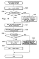
- the cause of the interruption is not the forcible cut-off of the power supply, that is, in the case of a negative answer at step S50, on the other hand, it is determined that the interruption is caused by either the operation of the power switch 92a on the switch panel 92 in the printer 1 to turn the power source 91 off or the operation of the cartridge switch 92b on the switch panel 92 to give an instruction of replacement of the ink cartridge.
- the program accordingly continues the printing operation in progress by a preset unit, for example, up to the end of one raster line, and calculates the remaining quantities of inks at step S51. The calculation is performed according to the flowchart of Fig. 14.
- the printer 1 stores the information relating to the remaining quantities of inks in different formats of addressing in the EEPROM 90 and in the storage elements 80 of the ink cartridges 107K and 107F.
- Memories of adequate specifications are thus respectively applicable for the EEPROM 90 and the storage elements 80, based on the requirements of the storage capacity, the speed of writing and reading operations, and the number of signal lines. This effectively reduces the size of the ink cartridges 107K and 107F and attains the resource saving effect.
- the EEPROM of the serial access type is used for each storage element 80.
- the control IC 200 mounted on the carriage 101 carries out the conversion of the format of addressing (8 bits, parallel) in the EEPROM 90 of the printer main body 100 into a different format of addressing, that is, the number of pulses of the clock signal CLK.
- the control IC 200 is disposed in the vicinity of the storage elements 80 that are serially accessed. This arrangement desirably shortens the length of the signal line connecting the control IC 200 with each storage element 80, thereby enhancing the reliability of data transmission.
- control IC 200 carries out the conversion of the storage format of addressing.
- This arrangement favorably decreases the loading to the controller 46 included in the print controller 40.
- the only action required for the print controller 40 is to output the power down signal NMI.
- This extremely shortens the time period required for the processing. This advantage is extremely significant when only a limited time period is provided for the processing, for example, at the time of forcible cut-off of the power supply.
- the data on the remaining quantities of inks, which are finally written into the respective storage elements 80 of the ink cartridges 107K and 107F, are temporarily registered in the RAM 210 on the control board 205.
- This arrangement does not require the time-consuming process of reading the respective pieces of information from the EEPROM 90 and writing the pieces of information into the storage element 80 in response to each demand. This accordingly facilitates the writing operation of data into the storage elements 80 of the ink cartridges 107K and 107F.
- the transmission of information between the print controller 40 and the storage elements 80 is implemented using the signal lines, through which the driving signal is transmitted to the respective piezoelectric vibrators 17 on the print head 10. This arrangement desirably simplifies the configuration of the signal lines between the print controller 40 and the carriage 101.
- the transfer controller 220 disposed on the control board 205 mounted on the carriage 101 specifies whether the input signal is to be transmitted to the driving circuit 230 or to be transmitted to the control IC 200.
- the print controller 40 is thus not in charge of the final transmission of information. This desirably simplifies the processing executed by the print controller 40.
- ferroelectric memories may replace the memory cells 81 in the storage elements 80 and the EEPROM 90.
- the storage elements 80 may not be incorporated in the respective ink cartridges 107K and 107F, but may be exposed to the outside.
- Fig. 16 shows a color ink cartridge 500 having an exposed storage element.
- the ink cartridge 500 includes a vessel 51 substantially formed in the shape of a rectangular parallelepiped, a porous body (not shown) that is impregnated with ink and accommodated in the vessel 51, and a cover member 53 that covers the top opening of the vessel 51.
- the vessel 51 is parted into five ink chambers (like the ink chambers 107C, 107LC, 107M, 107LM, and 107Y in the ink cartridge 107F discussed in the above embodiment), which separately keep five different color inks.
- Ink supply inlets 54 for the respective color inks are formed at specific positions on the bottom face of the vessel 51.
- the ink supply inlets 54 at the specific positions face ink supply needles (not shown here) when the ink cartridge 500 is attached to a cartridge attachment unit of a printer main body (not shown here).
- a pair of extensions 56 are integrally formed with the upper end of an upright wall 55, which is located on the side of the ink supply inlets 54.
- the extensions 56 receive projections of a lever (not shown here) fixed to the printer main body.
- the extensions 56 are located on both side ends of the upright wall 55 and respectively have ribs 56a.
- a triangular rib 57 is also formed between the lower face of each extension 56 and the upright wall 55.
- the vessel 51 also has a check recess 59, which prevents the ink cartridge 500 from being attached to the unsuitable cartridge attachment unit mistakenly.
- the upright wall 55 also has a recess 58 that is located on the substantial center of the width of the ink cartridge 500.
- a circuit board 31 is mounted on the recess 58.
- the circuit board 31 has a plurality of contacts, which are located to face contacts on the printer main body, and a storage element (not shown) mounted on the rear face thereof.
- the upright wall 55 is further provided with projections 55a and 55b and extensions 55c and 55d for positioning the circuit board 31.
- the structure of the above embodiment utilizes the transfer controller 220, in order to make the signal lines to the control IC 200 completely separate from the signal lines to the driving circuit 230.
- One modified arrangement provides specific terminals in the control IC 200 and the driving circuit 230 to selectively and exclusively enable the control IC 200 and the driving circuit 230.
- this modified structure there is, no requirement of completely separating the signals lines to the control IC 200 from the signal lines to the driving circuit 230.
- this modified structure connects the signal lines to the control IC 200 with the signal lines to the driving circuit 230 through wired communication.
- the selection control signal SSL is used to exclusively enable either the control IC 200 or the driving circuit 230.
- the selection control signal SSL is not input into the driving circuit 230 but is used only to enable the control IC 200.
- the piezoelectric vibrators 17 are not driven unless the driving signal COM is output. Output of the data to the signal lines SG1 through SG3 accordingly does not lead to the wrong activation of the driving circuit 230.
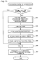
- Another modified structure places the RAM 210 under the control of the transfer controller 220 as shown in Fig. 18.
- the data on the remaining quantities of inks to be written into the storage elements 80 are temporarily registered in the RAM Z10, whereas recording data SI to be transferred to the driving circuit 230 are also temporarily stored in the RAM 210 as a buffer.
- the recording data SI are successively supplied to the driving circuit 230 synchronously with the clock signal CLK.
- the buffer is thus favorably used to provide data at an adequate timing.
- This buffer also works as the memory, in which pieces of information on the remaining quantities of inks to be written into the storage elements 80 are registered temporarily. This arrangement desirably reduces the number of required parts and thereby the manufacturing cost.
- the data on the remaining quantities of inks are transferred as the recording data SI synchronously with the clock signal CLK and set in the shift registers 13A through 13N.
- the subsequent output of the latch signal LAT sets the data on the remaining quantities of inks in the latch circuit 14.
Landscapes
- Physics & Mathematics (AREA)
- Engineering & Computer Science (AREA)
- Mathematical Physics (AREA)
- General Engineering & Computer Science (AREA)
- General Physics & Mathematics (AREA)
- Theoretical Computer Science (AREA)
- Ink Jet (AREA)
- Accessory Devices And Overall Control Thereof (AREA)
Priority Applications (1)
| Application Number | Priority Date | Filing Date | Title |
|---|---|---|---|
| EP06014882A EP1728638A3 (de) | 1998-11-26 | 1999-11-26 | Drucker mit zugeordneter Tintenkassette |
Applications Claiming Priority (12)
| Application Number | Priority Date | Filing Date | Title |
|---|---|---|---|
| JP33633098 | 1998-11-26 | ||
| JP33633098 | 1998-11-26 | ||
| JP33633198 | 1998-11-26 | ||
| JP33633198 | 1998-11-26 | ||
| JP36749098 | 1998-12-24 | ||
| JP36749098 | 1998-12-24 | ||
| JP399399 | 1999-01-11 | ||
| JP399399 | 1999-01-11 | ||
| JP29602499 | 1999-10-18 | ||
| JP29602499 | 1999-10-18 | ||
| JP33400199 | 1999-11-25 | ||
| JP33400199A JP4314702B2 (ja) | 1998-11-26 | 1999-11-25 | 印刷装置、書込方法およびプリンタ |
Related Child Applications (1)
| Application Number | Title | Priority Date | Filing Date |
|---|---|---|---|
| EP06014882A Division EP1728638A3 (de) | 1998-11-26 | 1999-11-26 | Drucker mit zugeordneter Tintenkassette |
Publications (3)
| Publication Number | Publication Date |
|---|---|
| EP1004448A2 true EP1004448A2 (de) | 2000-05-31 |
| EP1004448A3 EP1004448A3 (de) | 2001-01-03 |
| EP1004448B1 EP1004448B1 (de) | 2006-09-27 |
Family
ID=27547802
Family Applications (2)
| Application Number | Title | Priority Date | Filing Date |
|---|---|---|---|
| EP99309442A Revoked EP1004448B1 (de) | 1998-11-26 | 1999-11-26 | Drucker mit zugeordneter Tintenkassette |
| EP06014882A Withdrawn EP1728638A3 (de) | 1998-11-26 | 1999-11-26 | Drucker mit zugeordneter Tintenkassette |
Family Applications After (1)
| Application Number | Title | Priority Date | Filing Date |
|---|---|---|---|
| EP06014882A Withdrawn EP1728638A3 (de) | 1998-11-26 | 1999-11-26 | Drucker mit zugeordneter Tintenkassette |
Country Status (8)
| Country | Link |
|---|---|
| US (7) | US6631967B1 (de) |
| EP (2) | EP1004448B1 (de) |
| JP (1) | JP4314702B2 (de) |
| KR (1) | KR100623120B1 (de) |
| CN (3) | CN1528594A (de) |
| AT (1) | ATE340702T1 (de) |
| DE (1) | DE69933352T2 (de) |
| ES (1) | ES2272041T3 (de) |
Cited By (7)
| Publication number | Priority date | Publication date | Assignee | Title |
|---|---|---|---|---|
| GB2385560A (en) * | 2002-02-22 | 2003-08-27 | Unicorn Image Products Co Ltd | Ink cartridge having micro-controller with an embedded non-volatile EEPROM memory for storing cartridge identification and ink remaining data |
| EP1970201A3 (de) * | 2007-03-12 | 2009-11-25 | Canon Finetech Inc. | Drucksystem |
| EP2263146A1 (de) * | 2008-03-14 | 2010-12-22 | Hewlett-Packard Development Company, L.P. | Sicherer zugang zu flüssigkeitskassettenspeicher |
| CN102371786A (zh) * | 2010-08-23 | 2012-03-14 | 精工爱普生株式会社 | 存储装置、电路基板、液体容器以及系统 |
| EP1213148B2 (de) † | 2000-12-05 | 2015-10-14 | Seiko Epson Corporation | Druckvorrichtung und zugehörige Tintenpatrone |
| EP2998122A4 (de) * | 2013-05-17 | 2016-06-29 | Zhuhai Ninestar Man Co Ltd | Tintenkastenchip, tintenkasten und strukturkörper |
| EP2423853A3 (de) * | 2010-08-30 | 2017-07-19 | Seiko Epson Corporation | Datenspeicherverarbeitungsvorrichtung in einer Druckvorrichtung, Druckvorrichtung und Datenspeicherverarbeitungsverfahren |
Families Citing this family (105)
| Publication number | Priority date | Publication date | Assignee | Title |
|---|---|---|---|---|
| ES2198912T3 (es) * | 1998-05-18 | 2004-02-01 | Seiko Epson Corporation | Impresora de chorro de tinta y cartucho de tinta. |
| MY125897A (en) | 1998-11-02 | 2006-08-30 | Seiko Epson Corp | Ink cartridge and printer using the same |
| JP4395943B2 (ja) | 1998-11-26 | 2010-01-13 | セイコーエプソン株式会社 | 印刷装置およびその情報の管理方法 |
| JP2001187457A (ja) * | 1998-11-26 | 2001-07-10 | Seiko Epson Corp | 印刷装置およびカートリッジ |
| JP2000218818A (ja) * | 1998-11-26 | 2000-08-08 | Seiko Epson Corp | インク容器およびそれを用いる印刷装置 |
| JP2000301738A (ja) | 1998-11-26 | 2000-10-31 | Seiko Epson Corp | インク容器の適正判断方法およびインク容器の適正を判断する印刷装置 |
| JP4314702B2 (ja) * | 1998-11-26 | 2009-08-19 | セイコーエプソン株式会社 | 印刷装置、書込方法およびプリンタ |
| US7018117B2 (en) * | 1999-01-25 | 2006-03-28 | Fargo Electronics, Inc. | Identification card printer ribbon cartridge |
| US7344325B2 (en) | 1999-01-25 | 2008-03-18 | Fargo Electronics, Inc. | Identification card printer having ribbon cartridge with cleaner roller |
| US7154519B2 (en) * | 1999-01-25 | 2006-12-26 | Fargo Electronics, Inc. | Printer and ribbon cartridge |
| JP2001096869A (ja) | 1999-10-04 | 2001-04-10 | Seiko Epson Corp | 記録装置、半導体装置および記録ヘッド装置 |
| CN1251867C (zh) * | 1999-10-04 | 2006-04-19 | 精工爱普生株式会社 | 喷墨式记录装置、半导体装置及记录头装置 |
| US6546212B1 (en) * | 1999-10-15 | 2003-04-08 | Canon Kabushiki Kaisha | Image forming apparatus and unit detachably attachable to the same image forming apparatus and information displaying system related to unit detachably attachable to the same image forming apparatus |
| DE19958941B4 (de) * | 1999-11-26 | 2006-11-09 | Francotyp-Postalia Gmbh | Verfahren zum Schutz eines Gerätes vor einem Betreiben mit unzulässigem Verbrauchsmaterial |
| ES2263517T3 (es) * | 2000-01-21 | 2006-12-16 | Seiko Epson Corporation | Un cartucho de tinta para su uso con un aparato de registro de inyeccion de tinta. |
| JP3631116B2 (ja) * | 2000-09-14 | 2005-03-23 | キヤノン株式会社 | 情報処理方法及び情報処理システム |
| EP1208986A1 (de) * | 2000-11-27 | 2002-05-29 | Océ-Technologies B.V. | Tintenstrahldrucksystem, Tintenbehälter und Herstellungsverfahren |
| US7292369B2 (en) * | 2000-12-28 | 2007-11-06 | Seiko Epson Corporation | Logo data generating method and system |
| US7280258B2 (en) * | 2001-01-05 | 2007-10-09 | Seiko Epson Corporation | Logo data generating system, logo data generating method, and data storage medium |
| JP4304868B2 (ja) * | 2001-02-05 | 2009-07-29 | コニカミノルタホールディングス株式会社 | メモリ装置を有する画像形成装置及び判断処理方法 |
| CA2379725C (en) * | 2001-04-03 | 2007-06-12 | Seiko Epson Corporation | Ink cartridge |
| US7433065B2 (en) * | 2001-08-16 | 2008-10-07 | Hewlett-Packard Development Company, L.P. | Image forming device consumable monitoring methods, consumable monitoring systems and image forming devices |
| US7430762B2 (en) | 2002-03-01 | 2008-09-30 | Fargo Electronics, Inc. | Identification card manufacturing security |
| JP2004066467A (ja) * | 2002-08-01 | 2004-03-04 | Canon Inc | 記録装置とその制御方法及び記録ヘッド、記録ヘッド用素子基体、液体吐出装置、液体吐出ヘッド並びに液体吐出ヘッド用素子基体 |
| US7296864B2 (en) * | 2002-08-01 | 2007-11-20 | Canon Kabushiki Kaisha | Control method for printing apparatus |
| JP2004237667A (ja) * | 2003-02-07 | 2004-08-26 | Canon Inc | データ転送方法 |
| JP3808834B2 (ja) * | 2003-02-17 | 2006-08-16 | 理想科学工業株式会社 | 画像形成方法および装置 |
| US20050007812A1 (en) * | 2003-06-03 | 2005-01-13 | Seiko Epson Corporation | Image forming apparatus and method of forming image |
| US7259588B2 (en) * | 2003-07-29 | 2007-08-21 | Lexmark International Inc. | Tri-state detection circuit for use in devices associated with an imaging system |
| US7014301B2 (en) * | 2003-07-30 | 2006-03-21 | Hewlett-Packard Development Company, L.P. | Printing device configured to receive a plurality of different cartridge types |
| US7878505B2 (en) | 2003-08-19 | 2011-02-01 | Hid Global Corporation | Credential substrate rotator and processing module |
| US7198352B2 (en) * | 2004-01-21 | 2007-04-03 | Kia Silverbrook | Inkjet printer cradle with cartridge stabilizing mechanism |
| US7731327B2 (en) | 2004-01-21 | 2010-06-08 | Silverbrook Research Pty Ltd | Desktop printer with cartridge incorporating printhead integrated circuit |
| US7645025B2 (en) | 2004-01-21 | 2010-01-12 | Silverbrook Research Pty Ltd | Inkjet printer cartridge with two printhead integrated circuits |
| US20050157125A1 (en) * | 2004-01-21 | 2005-07-21 | Silverbrook Research Pty Ltd | Inkjet printer cartridge with integral shield |
| US7364264B2 (en) * | 2004-01-21 | 2008-04-29 | Silverbrook Research Pty Ltd | Inkjet printer cradle with single drive motor performing multiple functions |
| US7469989B2 (en) | 2004-01-21 | 2008-12-30 | Silverbrook Research Pty Ltd | Printhead chip having longitudinal ink supply channels interrupted by transverse bridges |
| US7360868B2 (en) * | 2004-01-21 | 2008-04-22 | Silverbrook Research Pty Ltd | Inkjet printer cartridge with infrared ink delivery capabilities |
| US20050157128A1 (en) * | 2004-01-21 | 2005-07-21 | Silverbrook Research Pty Ltd | Pagewidth inkjet printer cartridge with end electrical connectors |
| US7328985B2 (en) * | 2004-01-21 | 2008-02-12 | Silverbrook Research Pty Ltd | Inkjet printer cartridge refill dispenser with security mechanism |
| US7524016B2 (en) * | 2004-01-21 | 2009-04-28 | Silverbrook Research Pty Ltd | Cartridge unit having negatively pressurized ink storage |
| US20050157112A1 (en) * | 2004-01-21 | 2005-07-21 | Silverbrook Research Pty Ltd | Inkjet printer cradle with shaped recess for receiving a printer cartridge |
| US7374355B2 (en) | 2004-01-21 | 2008-05-20 | Silverbrook Research Pty Ltd | Inkjet printer cradle for receiving a pagewidth printhead cartridge |
| US7083273B2 (en) * | 2004-01-21 | 2006-08-01 | Silverbrook Research Pty Ltd | Inkjet printer cartridge with uniform compressed air distribution |
| US7367647B2 (en) * | 2004-01-21 | 2008-05-06 | Silverbrook Research Pty Ltd | Pagewidth inkjet printer cartridge with ink delivery member |
| US7448734B2 (en) * | 2004-01-21 | 2008-11-11 | Silverbrook Research Pty Ltd | Inkjet printer cartridge with pagewidth printhead |
| US7303255B2 (en) | 2004-01-21 | 2007-12-04 | Silverbrook Research Pty Ltd | Inkjet printer cartridge with a compressed air port |
| US7441865B2 (en) | 2004-01-21 | 2008-10-28 | Silverbrook Research Pty Ltd | Printhead chip having longitudinal ink supply channels |
| US20050157000A1 (en) * | 2004-01-21 | 2005-07-21 | Silverbrook Research Pty Ltd | Inkjet printer cradle with end data and power contacts |
| SG113577A1 (en) | 2004-01-21 | 2005-08-29 | Seiko Epson Corp | Liquid cartridge, printer, and method for controlling printer |
| US7097291B2 (en) | 2004-01-21 | 2006-08-29 | Silverbrook Research Pty Ltd | Inkjet printer cartridge with ink refill port having multiple ink couplings |
| US7425050B2 (en) * | 2004-01-21 | 2008-09-16 | Silverbrook Research Pty Ltd | Method for facilitating maintenance of an inkjet printer having a pagewidth printhead |
| JP4574205B2 (ja) * | 2004-03-31 | 2010-11-04 | キヤノン株式会社 | 記録装置 |
| US20050270325A1 (en) * | 2004-06-07 | 2005-12-08 | Cavill Barry R | System and method for calibrating ink ejecting nozzles in a printer/scanner |
| US7920281B2 (en) * | 2004-06-21 | 2011-04-05 | Sharp Laboratories Of America, Inc. | Imaging job monitoring with reduced content image |
| US9116641B2 (en) | 2004-11-30 | 2015-08-25 | Panduit Corp. | Market-based labeling system and method |
| JP4047328B2 (ja) | 2004-12-24 | 2008-02-13 | キヤノン株式会社 | 液体収納容器、該容器を用いる液体供給システムおよび記録装置、並びに前記容器用回路基板 |
| US20060164465A1 (en) * | 2005-01-21 | 2006-07-27 | Steinmetz Charles R | Receptacle for colored marking material container |
| US7037011B1 (en) * | 2005-07-07 | 2006-05-02 | Amano Cincinnati, Inc. | Ribbon cartridge having updatable data communication component |
| US8099187B2 (en) | 2005-08-18 | 2012-01-17 | Hid Global Corporation | Securely processing and tracking consumable supplies and consumable material |
| KR100641658B1 (ko) * | 2005-10-25 | 2006-11-10 | 주식회사 잉크테크 | 프린터용 잉크 카트리지 |
| JP4144637B2 (ja) | 2005-12-26 | 2008-09-03 | セイコーエプソン株式会社 | 印刷材収容体、基板、印刷装置および印刷材収容体を準備する方法 |
| JP5114878B2 (ja) * | 2006-06-30 | 2013-01-09 | ブラザー工業株式会社 | インクジェット記録装置 |
| JP4952093B2 (ja) | 2006-06-30 | 2012-06-13 | ブラザー工業株式会社 | インクジェット記録装置 |
| JP2008012677A (ja) * | 2006-06-30 | 2008-01-24 | Brother Ind Ltd | 画像記録装置 |
| JP4935208B2 (ja) * | 2006-07-01 | 2012-05-23 | ブラザー工業株式会社 | 画像記録装置 |
| CN101390019B (zh) | 2006-11-29 | 2012-04-04 | 佳能株式会社 | 成像设备、通信设备以及墨盒 |
| US7731335B2 (en) * | 2006-12-21 | 2010-06-08 | Eastman Kodak Company | Data storage device mounting arrangement for printing device |
| US8161199B1 (en) * | 2007-06-25 | 2012-04-17 | Marvell International Ltd. | Smart printer cartridge |
| JP5171448B2 (ja) * | 2007-07-31 | 2013-03-27 | キヤノン株式会社 | 画像形成装置及びその制御方法 |
| US7758138B2 (en) * | 2007-10-01 | 2010-07-20 | Seiko Epson Corporation | Liquid jetting apparatus and control method configured to reduce effects of electrical fluctuations |
| KR101239767B1 (ko) | 2007-11-12 | 2013-03-06 | 삼성전자주식회사 | 화상형성장치 및 그 제어방법 |
| US9707752B2 (en) * | 2007-11-14 | 2017-07-18 | Hewlett-Packard Development Company, L.P. | Inkjet print head with shared data lines |
| US8388123B2 (en) * | 2008-06-08 | 2013-03-05 | Hewlett-Packard Development Company, L.P. | Fluid cartridge having feature to clear bracket riser surfaces |
| JP5663843B2 (ja) * | 2009-04-01 | 2015-02-04 | セイコーエプソン株式会社 | 記憶装置、基板、液体容器、不揮発性のデータ記憶部の制御方法、ホスト回路と着脱可能な記憶装置を含むシステム |
| US8782326B2 (en) * | 2009-04-01 | 2014-07-15 | Seiko Epson Corporation | Memory device and system including a memory device electronically connectable to a host circuit |
| CN101885270B (zh) | 2009-05-13 | 2012-09-05 | 珠海纳思达企业管理有限公司 | 一种喷墨打印机上的适配器及与之配套使用的墨盒 |
| JP5568928B2 (ja) * | 2009-09-08 | 2014-08-13 | セイコーエプソン株式会社 | 記憶装置、基板、液体容器及びシステム |
| US8646770B2 (en) | 2009-09-18 | 2014-02-11 | Hid Global Corporation | Card substrate rotator with lift mechanism |
| CN101734018B (zh) * | 2009-12-02 | 2011-11-09 | 珠海艾派克微电子有限公司 | 打印装置的存储芯片 |
| JP5676890B2 (ja) * | 2010-02-26 | 2015-02-25 | キヤノン株式会社 | 記録装置 |
| JP5170135B2 (ja) * | 2010-03-17 | 2013-03-27 | ブラザー工業株式会社 | 画像記録装置 |
| JP5750836B2 (ja) * | 2010-05-27 | 2015-07-22 | セイコーエプソン株式会社 | 流体噴射装置 |
| KR101760343B1 (ko) * | 2010-08-23 | 2017-07-21 | 에스프린팅솔루션 주식회사 | 화상형성장치 및 그 장치에서 축소 이미지를 인쇄하는 방법 |
| JP5672927B2 (ja) | 2010-10-08 | 2015-02-18 | セイコーエプソン株式会社 | 記憶装置、ホスト装置、回路基板、液体容器及びシステム |
| JP5621496B2 (ja) | 2010-10-15 | 2014-11-12 | セイコーエプソン株式会社 | 記憶装置、回路基板、液体容器及びシステム |
| CN102009530B (zh) * | 2010-10-15 | 2014-08-13 | 珠海天威技术开发有限公司 | 成像装置、其改装方法及耗材容器 |
| DE102011103840A1 (de) * | 2011-06-01 | 2012-12-06 | Trützschler GmbH & Co Kommanditgesellschaft | Vorrichtung an einer Spinnereivorbereitungsmaschine, z.B. Faserflockenspeiser, Karde, Reiniger o. dgl. zum Zu- und/oder Abfördern von Fasermaterial |
| JP2013033225A (ja) * | 2011-06-30 | 2013-02-14 | Canon Inc | 撮像装置及び画像形成装置 |
| JP5737101B2 (ja) * | 2011-09-15 | 2015-06-17 | ブラザー工業株式会社 | 印刷装置および印刷装置の制御方法 |
| US9592664B2 (en) | 2011-09-27 | 2017-03-14 | Hewlett-Packard Development Company, L.P. | Circuit that selects EPROMs individually and in parallel |
| DE102012100125A1 (de) * | 2012-01-10 | 2013-07-11 | OCé PRINTING SYSTEMS GMBH | Verfahren zum Reinigen der Düsen mindestens eines Tintendruckkopfes mit einem Spülmedium bei einem Tintendruckgerät |
| JP6051595B2 (ja) * | 2012-05-21 | 2016-12-27 | セイコーエプソン株式会社 | カートリッジ |
| US9088752B2 (en) * | 2012-06-15 | 2015-07-21 | Hewlett-Packard Development Company, L.P. | Generating a print preview |
| US9063462B2 (en) | 2012-06-29 | 2015-06-23 | Static Control Components, Inc. | Network printer system |
| US9883053B2 (en) * | 2013-01-28 | 2018-01-30 | Hewlett-Packard Development Company, L.P. | Configuring printer operation using colorant information on colorant units |
| TWI555650B (zh) * | 2013-01-31 | 2016-11-01 | 誠研科技股份有限公司 | 可儲存資訊之熱轉印列印系統 |
| MX358312B (es) * | 2013-12-03 | 2018-08-13 | Static Control Components Inc | Sistema de impresora de red. |
| JP6281342B2 (ja) | 2014-03-17 | 2018-02-21 | セイコーエプソン株式会社 | 液体供給ユニット |
| JP6624801B2 (ja) * | 2014-05-30 | 2019-12-25 | キヤノン株式会社 | 液体吐出カートリッジ及び液体吐出装置 |
| JP6444195B2 (ja) * | 2015-02-04 | 2018-12-26 | キヤノン株式会社 | 生成装置、記録装置、生成方法、プログラム、及び記憶媒体 |
| JP6691675B2 (ja) * | 2015-08-31 | 2020-05-13 | ブラザー工業株式会社 | 制御プログラム、および制御装置 |
| US10419623B2 (en) * | 2017-02-21 | 2019-09-17 | Seiko Epson Corporation | Measuring apparatus and printing apparatus |
| CN109605941B (zh) * | 2019-01-30 | 2020-03-10 | 北海绩迅电子科技有限公司 | 一种内胆墨盒及其加工方法 |
| JP7379009B2 (ja) * | 2019-08-09 | 2023-11-14 | キヤノン株式会社 | 画像処理装置、画像印刷装置および画像処理方法 |
Citations (1)
| Publication number | Priority date | Publication date | Assignee | Title |
|---|---|---|---|---|
| JPS62184856A (ja) | 1986-02-12 | 1987-08-13 | Canon Inc | インクカートリッジおよび記録装置 |
Family Cites Families (85)
| Publication number | Priority date | Publication date | Assignee | Title |
|---|---|---|---|---|
| JPS58194550A (ja) * | 1982-05-10 | 1983-11-12 | Canon Inc | インクカセット |
| KR870001840B1 (ko) * | 1983-06-08 | 1987-10-15 | 미쓰비시덴기 가부시기가이샤 | 텔레비젼 수신기의 프린터장치 |
| US4571599A (en) * | 1984-12-03 | 1986-02-18 | Xerox Corporation | Ink cartridge for an ink jet printer |
| US4937791A (en) * | 1988-06-02 | 1990-06-26 | The California Institute Of Technology | High performance dynamic ram interface |
| WO1990000974A1 (de) | 1988-07-25 | 1990-02-08 | Siemens Aktiengesellschaft | Anordnung für druckeinrichtungen zur überwachung von druckmedium enthaltenden vorratsbehältern |
| JP2933347B2 (ja) * | 1989-03-20 | 1999-08-09 | ヒューレット・パッカード・カンパニー | インクジェット印刷ヘッド |
| US5049898A (en) * | 1989-03-20 | 1991-09-17 | Hewlett-Packard Company | Printhead having memory element |
| US4961088A (en) | 1989-04-20 | 1990-10-02 | Xerox Corporation | Monitor/warranty system for electrostatographic reproducing machines using replaceable cartridges |
| DE69032780T2 (de) | 1989-08-05 | 1999-06-02 | Canon K.K., Tokio/Tokyo | Tintenstrahlaufzeichnungsgerät und Tintenkassette dafür |
| JP3222454B2 (ja) | 1990-02-02 | 2001-10-29 | キヤノン株式会社 | インクタンクカートリッジ |
| USRE36279E (en) | 1990-02-02 | 1999-08-24 | Canon Kabushiki Kaisha | Ink jet apparatus and ink jet cartridge therefor |
| JP2584879B2 (ja) | 1990-02-23 | 1997-02-26 | キヤノン株式会社 | ファクシミリ装置 |
| US6566091B1 (en) * | 1990-09-25 | 2003-05-20 | Genentech, Inc. | Neurotrophic factor |
| US5861897A (en) | 1991-01-19 | 1999-01-19 | Canon Kabushiki Kaisha | Inkjet recording apparatus with a memory device disposed substantially within boundaries if a recording head unit |
| JP2779982B2 (ja) | 1991-06-19 | 1998-07-23 | 富士写真フイルム株式会社 | 感光性組成物 |
| JPH057924A (ja) * | 1991-07-01 | 1993-01-19 | Showa Alum Corp | 押出用ホローダイス |
| JP2582487B2 (ja) | 1991-07-12 | 1997-02-19 | インターナショナル・ビジネス・マシーンズ・コーポレイション | 半導体メモリを用いた外部記憶システム及びその制御方法 |
| JPH0520275A (ja) | 1991-07-17 | 1993-01-29 | Sharp Corp | 小型情報端末機 |
| US5410641A (en) | 1991-10-23 | 1995-04-25 | Seiko Epson Corporation | Intelligent cartridge for attachment to a printer to perform image processing tasks in a combination image processing system and method of image processing |
| EP0715959B1 (de) * | 1991-12-11 | 1999-06-30 | Canon Kabushiki Kaisha | Tintenstrahlkassette und Titenbehälter |
| JP3192456B2 (ja) * | 1992-01-20 | 2001-07-30 | キヤノン株式会社 | 画像記録装置及び情報設定装置 |
| EP0559122B1 (de) * | 1992-03-02 | 1997-06-11 | Seiko Epson Corporation | Farbstrahldrucker, damit ausgerüstetes elektronisches Gerät und Betriebsverfahren dafür |
| JPH0676559A (ja) * | 1992-06-26 | 1994-03-18 | Mitsubishi Electric Corp | ファーストインファーストアウトメモリ装置 |
| JP2839995B2 (ja) * | 1992-10-14 | 1998-12-24 | キヤノン株式会社 | 記録装置 |
| US6189989B1 (en) * | 1993-04-12 | 2001-02-20 | Canon Kabushiki Kaisha | Embroidering using ink jet printing apparatus |
| GB9307623D0 (en) * | 1993-04-13 | 1993-06-02 | Jonhig Ltd | Data writing to eeprom |
| JPH06336070A (ja) * | 1993-05-27 | 1994-12-06 | Tokyo Electric Co Ltd | プリンタユニット及びプリンタ装置 |
| JP3055390B2 (ja) * | 1994-02-23 | 2000-06-26 | 日本電気株式会社 | 画像処理装置 |
| CN1052094C (zh) * | 1994-05-21 | 2000-05-03 | 华邦电子股份有限公司 | 串行存取的存贮器装置 |
| JPH07323645A (ja) * | 1994-05-31 | 1995-12-12 | Canon Inc | 記録装置 |
| US5610635A (en) | 1994-08-09 | 1997-03-11 | Encad, Inc. | Printer ink cartridge with memory storage capacity |
| US5646660A (en) | 1994-08-09 | 1997-07-08 | Encad, Inc. | Printer ink cartridge with drive logic integrated circuit |
| WO1996005061A1 (en) * | 1994-08-09 | 1996-02-22 | Encad, Inc. | Printer ink cartridge |
| US5694157A (en) * | 1994-10-28 | 1997-12-02 | Hewlett-Packard Company | Multiple wiper servicing system for inkjet printheads |
| FR2726934B1 (fr) * | 1994-11-10 | 1997-01-17 | Sgs Thomson Microelectronics | Procede de lecture anticipee de memoire a acces serie et memoire s'y rapportant |
| US6065824A (en) * | 1994-12-22 | 2000-05-23 | Hewlett-Packard Company | Method and apparatus for storing information on a replaceable ink container |
| US5812156A (en) | 1997-01-21 | 1998-09-22 | Hewlett-Packard Company | Apparatus controlled by data from consumable parts with incorporated memory devices |
| US5699091A (en) | 1994-12-22 | 1997-12-16 | Hewlett-Packard Company | Replaceable part with integral memory for usage, calibration and other data |
| US5491540A (en) * | 1994-12-22 | 1996-02-13 | Hewlett-Packard Company | Replacement part with integral memory for usage and calibration data |
| JP3726295B2 (ja) | 1994-12-26 | 2005-12-14 | 株式会社デンソー | 車両用制御装置 |
| JPH08187854A (ja) | 1995-01-10 | 1996-07-23 | Canon Inc | 記録装置 |
| JPH08197748A (ja) * | 1995-01-30 | 1996-08-06 | Copyer Co Ltd | インクジェットプリンタ |
| EP0728587B1 (de) * | 1995-02-21 | 2004-04-28 | Canon Kabushiki Kaisha | Tintenstrahldrucker mit austauschbaren Aufzeichnungsmitteln, ein Steuerverfahren zur Reinigung hierfür und Tintenstrahldrucker mit einer Handhabevorrichtung für die Tintenrestmenge |
| JPH08224885A (ja) | 1995-02-23 | 1996-09-03 | Canon Inc | 記録装置 |
| US5629578A (en) * | 1995-03-20 | 1997-05-13 | Martin Marietta Corp. | Integrated composite acoustic transducer array |
| US5877788A (en) * | 1995-05-09 | 1999-03-02 | Moore Business Forms, Inc. | Cleaning fluid apparatus and method for continuous printing ink-jet nozzle |
| JPH08310007A (ja) * | 1995-05-19 | 1996-11-26 | Oki Data:Kk | シリアルプリンタ |
| JPH091823A (ja) | 1995-06-23 | 1997-01-07 | Nec Eng Ltd | 印字装置のインク残量検出回路 |
| JP3615873B2 (ja) | 1995-07-04 | 2005-02-02 | ペンタックス株式会社 | 再圧縮禁止制御装置 |
| JPH0948120A (ja) | 1995-08-09 | 1997-02-18 | Mita Ind Co Ltd | 記録ヘッド及びインクジェット記録装置 |
| JP3281520B2 (ja) * | 1995-10-02 | 2002-05-13 | キヤノン株式会社 | 記録装置 |
| US5610873A (en) * | 1996-03-21 | 1997-03-11 | National Science Council Of R.O.C. | Address generator for generating a plurality of addresses to be used in zig-zag scanning of contents of memory array |
| US5930553A (en) | 1997-04-25 | 1999-07-27 | Hewlett-Packard Company | Image forming and office automation device consumable with memory |
| JPH09314861A (ja) * | 1996-06-04 | 1997-12-09 | Canon Inc | インクジェット記録装置およびインクジェットユニット |
| JP3309725B2 (ja) * | 1996-08-02 | 2002-07-29 | セイコーエプソン株式会社 | インクカートリッジ |
| JPH10166615A (ja) | 1996-12-09 | 1998-06-23 | Nec Niigata Ltd | インクジェット記録装置における記録量制御方法およびシステム |
| JPH10105454A (ja) * | 1996-09-27 | 1998-04-24 | Sharp Corp | マルチポートメモリおよびマルチポートメモリを備えた表示システム |
| US6375301B1 (en) | 1997-01-21 | 2002-04-23 | Hewlett-Packard Company | Replaceable cartridge, kit and method for flushing ink from an inkjet printer |
| US6227638B1 (en) | 1997-01-21 | 2001-05-08 | Hewlett-Packard Company | Electrical refurbishment for ink delivery system |
| US5788388A (en) | 1997-01-21 | 1998-08-04 | Hewlett-Packard Company | Ink jet cartridge with ink level detection |
| US6126265A (en) | 1997-01-21 | 2000-10-03 | Hewlett-Packard Company | Ink jet printer service station controlled by data from consumable parts with incorporated memory devices |
| US6168262B1 (en) * | 1997-01-30 | 2001-01-02 | Hewlett-Packard Company | Electrical interconnect for replaceable ink containers |
| JPH10211693A (ja) * | 1997-01-31 | 1998-08-11 | Canon Inc | プリント装置およびプリント方法 |
| US5975677A (en) | 1997-04-30 | 1999-11-02 | Hewlett-Packard Co. | Multiple cartridge printhead assembly for use in an inkjet printing system |
| US6227643B1 (en) | 1997-05-20 | 2001-05-08 | Encad, Inc. | Intelligent printer components and printing system |
| JP3288954B2 (ja) * | 1997-06-19 | 2002-06-04 | キヤノン株式会社 | 記録装置及び該記録装置の制御方法 |
| US6158837A (en) * | 1997-09-19 | 2000-12-12 | Xerox Corporation | Printer having print mode for non-qualified marking material |
| US6109723A (en) | 1998-03-12 | 2000-08-29 | Hewlett-Packard Company | Method and apparatus for determining an optimum print density for an ink jet printer |
| US6264301B1 (en) * | 1998-05-11 | 2001-07-24 | Hewlett-Packard Company | Method and apparatus for identifying parameters in a replaceable printing component |
| US6019449A (en) | 1998-06-05 | 2000-02-01 | Hewlett-Packard Company | Apparatus controlled by data from consumable parts with incorporated memory devices |
| US6155664A (en) | 1998-06-19 | 2000-12-05 | Lexmark International, Inc. | Off-carrier inkjet print supply with memory |
| MY125897A (en) * | 1998-11-02 | 2006-08-30 | Seiko Epson Corp | Ink cartridge and printer using the same |
| JP2000218818A (ja) | 1998-11-26 | 2000-08-08 | Seiko Epson Corp | インク容器およびそれを用いる印刷装置 |
| JP2000301738A (ja) | 1998-11-26 | 2000-10-31 | Seiko Epson Corp | インク容器の適正判断方法およびインク容器の適正を判断する印刷装置 |
| JP2001187457A (ja) | 1998-11-26 | 2001-07-10 | Seiko Epson Corp | 印刷装置およびカートリッジ |
| JP4314702B2 (ja) | 1998-11-26 | 2009-08-19 | セイコーエプソン株式会社 | 印刷装置、書込方法およびプリンタ |
| JP4395943B2 (ja) | 1998-11-26 | 2010-01-13 | セイコーエプソン株式会社 | 印刷装置およびその情報の管理方法 |
| JP2000270129A (ja) | 1999-03-12 | 2000-09-29 | Ryuji Ito | インクジェット式プリンタを備えた印画装置 |
| JP4106156B2 (ja) | 1999-07-07 | 2008-06-25 | 理想科学工業株式会社 | 孔版印刷装置 |
| WO2001005596A1 (fr) | 1999-07-14 | 2001-01-25 | Seiko Epson Corporation | Cartouche d'encre, imprimante a jet d'encre, procede de remplacement d'une cartouche d'encre |
| EP1080912A3 (de) | 1999-08-31 | 2001-09-05 | Seiko Epson Corporation | Tintenpatroneverwaltungssystem, Drucker und Tintenpatrone |
| US6497469B1 (en) | 1999-08-31 | 2002-12-24 | Seiko Epson Corporation | Print system, ink jet printer and ink cartridge |
| CN1251867C (zh) | 1999-10-04 | 2006-04-19 | 精工爱普生株式会社 | 喷墨式记录装置、半导体装置及记录头装置 |
| JP2001096869A (ja) | 1999-10-04 | 2001-04-10 | Seiko Epson Corp | 記録装置、半導体装置および記録ヘッド装置 |
| CA2379725C (en) | 2001-04-03 | 2007-06-12 | Seiko Epson Corporation | Ink cartridge |
-
1999
- 1999-11-25 JP JP33400199A patent/JP4314702B2/ja not_active Expired - Fee Related
- 1999-11-26 CN CNA2004100322355A patent/CN1528594A/zh active Pending
- 1999-11-26 CN CNB2005100524972A patent/CN100464983C/zh not_active Expired - Fee Related
- 1999-11-26 AT AT99309442T patent/ATE340702T1/de not_active IP Right Cessation
- 1999-11-26 DE DE69933352T patent/DE69933352T2/de not_active Expired - Lifetime
- 1999-11-26 KR KR1019990052968A patent/KR100623120B1/ko not_active IP Right Cessation
- 1999-11-26 EP EP99309442A patent/EP1004448B1/de not_active Revoked
- 1999-11-26 CN CNB991277171A patent/CN1151026C/zh not_active Expired - Lifetime
- 1999-11-26 ES ES99309442T patent/ES2272041T3/es not_active Expired - Lifetime
- 1999-11-26 US US09/449,732 patent/US6631967B1/en not_active Expired - Lifetime
- 1999-11-26 EP EP06014882A patent/EP1728638A3/de not_active Withdrawn
-
2002
- 2002-07-18 US US10/197,408 patent/US7134738B2/en not_active Expired - Fee Related
- 2002-07-18 US US10/197,407 patent/US20020196302A1/en not_active Abandoned
-
2003
- 2003-05-27 US US10/445,036 patent/US6969140B2/en not_active Expired - Fee Related
- 2003-06-20 US US10/465,650 patent/US7267415B2/en not_active Expired - Lifetime
-
2006
- 2006-06-26 US US11/426,433 patent/US20060284947A1/en not_active Abandoned
-
2007
- 2007-04-25 US US11/740,071 patent/US20070188539A1/en not_active Abandoned
Patent Citations (1)
| Publication number | Priority date | Publication date | Assignee | Title |
|---|---|---|---|---|
| JPS62184856A (ja) | 1986-02-12 | 1987-08-13 | Canon Inc | インクカートリッジおよび記録装置 |
Cited By (16)
| Publication number | Priority date | Publication date | Assignee | Title |
|---|---|---|---|---|
| EP1213148B2 (de) † | 2000-12-05 | 2015-10-14 | Seiko Epson Corporation | Druckvorrichtung und zugehörige Tintenpatrone |
| GB2385560A (en) * | 2002-02-22 | 2003-08-27 | Unicorn Image Products Co Ltd | Ink cartridge having micro-controller with an embedded non-volatile EEPROM memory for storing cartridge identification and ink remaining data |
| WO2003070472A1 (en) * | 2002-02-22 | 2003-08-28 | Print-Rite.Unicorn Image Products Co. Ltd. Of Zhuhai | An intelligent ink cartridge and method for manufacturing the same |
| GB2385560B (en) * | 2002-02-22 | 2004-07-21 | Unicorn Image Products Co Ltd | An intelligent ink cartridge and method for manufacturing the same |
| US7344214B2 (en) | 2002-02-22 | 2008-03-18 | Print-Rite Unicorn Image Products Co., Ltd. Of Zhuhai | Intelligent ink cartridge and method for manufacturing the same |
| EP1970201A3 (de) * | 2007-03-12 | 2009-11-25 | Canon Finetech Inc. | Drucksystem |
| CN101971134B (zh) * | 2008-03-14 | 2013-03-27 | 惠普开发有限公司 | 对流体盒存储器的安全访问 |
| EP2263146A4 (de) * | 2008-03-14 | 2011-07-06 | Hewlett Packard Development Co | Sicherer zugang zu flüssigkeitskassettenspeicher |
| US8474943B2 (en) | 2008-03-14 | 2013-07-02 | Hewlett-Packard Development Company, L.P. | Secure access to fluid cartridge memory |
| EP2263146A1 (de) * | 2008-03-14 | 2010-12-22 | Hewlett-Packard Development Company, L.P. | Sicherer zugang zu flüssigkeitskassettenspeicher |
| CN102371786A (zh) * | 2010-08-23 | 2012-03-14 | 精工爱普生株式会社 | 存储装置、电路基板、液体容器以及系统 |
| EP2423803A3 (de) * | 2010-08-23 | 2013-09-18 | Seiko Epson Corporation | Speichervorrichtung, Leiterplatte, Flüssigkeitsbehälter und System |
| EP2423853A3 (de) * | 2010-08-30 | 2017-07-19 | Seiko Epson Corporation | Datenspeicherverarbeitungsvorrichtung in einer Druckvorrichtung, Druckvorrichtung und Datenspeicherverarbeitungsverfahren |
| EP2998122A4 (de) * | 2013-05-17 | 2016-06-29 | Zhuhai Ninestar Man Co Ltd | Tintenkastenchip, tintenkasten und strukturkörper |
| US9481181B2 (en) | 2013-05-17 | 2016-11-01 | Zhuhai Ninestar Management Co., Ltd. | Ink cartridge chip, ink cartridge, and structural body |
| EP3572233A1 (de) * | 2013-05-17 | 2019-11-27 | Zhuhai Ninestar Management Co., Ltd. | Tintenkartuschenchip, tintenkartusche und strukturkörper |
Also Published As
| Publication number | Publication date |
|---|---|
| CN1528594A (zh) | 2004-09-15 |
| CN1256207A (zh) | 2000-06-14 |
| CN1151026C (zh) | 2004-05-26 |
| EP1004448B1 (de) | 2006-09-27 |
| US20040095407A1 (en) | 2004-05-20 |
| US20070188539A1 (en) | 2007-08-16 |
| US6969140B2 (en) | 2005-11-29 |
| US20020196302A1 (en) | 2002-12-26 |
| DE69933352T2 (de) | 2007-04-19 |
| US20060284947A1 (en) | 2006-12-21 |
| CN100464983C (zh) | 2009-03-04 |
| EP1004448A3 (de) | 2001-01-03 |
| KR100623120B1 (ko) | 2006-09-12 |
| US7134738B2 (en) | 2006-11-14 |
| ES2272041T3 (es) | 2007-04-16 |
| CN1654217A (zh) | 2005-08-17 |
| KR20000035729A (ko) | 2000-06-26 |
| DE69933352D1 (de) | 2006-11-09 |
| ATE340702T1 (de) | 2006-10-15 |
| EP1728638A3 (de) | 2007-01-03 |
| US20030197751A1 (en) | 2003-10-23 |
| JP4314702B2 (ja) | 2009-08-19 |
| US20020180851A1 (en) | 2002-12-05 |
| EP1728638A2 (de) | 2006-12-06 |
| US7267415B2 (en) | 2007-09-11 |
| US6631967B1 (en) | 2003-10-14 |
| JP2001187456A (ja) | 2001-07-10 |
Similar Documents
| Publication | Publication Date | Title |
|---|---|---|
| EP1004448B1 (de) | Drucker mit zugeordneter Tintenkassette | |
| EP1004447B1 (de) | Drucker mit zugeordneter Tintenkassette | |
| EP1004450B1 (de) | Drucker mit zugeordneter Tintenkassette | |
| US6447090B1 (en) | Ink cartridge and printer using the same | |
| US7513590B2 (en) | Method of normality decision with regard to ink cartridge and printer actualizing the method | |
| JP4442711B2 (ja) | インク容器およびそれを用いる印刷装置 | |
| AU6369099A (en) | Ink cartridge and printer using the same | |
| JP2000158665A (ja) | インクジェット記録装置およびインク収容体 |
Legal Events
| Date | Code | Title | Description |
|---|---|---|---|
| PUAI | Public reference made under article 153(3) epc to a published international application that has entered the european phase |
Free format text: ORIGINAL CODE: 0009012 |
|
| AK | Designated contracting states |
Kind code of ref document: A2 Designated state(s): AT BE CH CY DE DK ES FI FR GB GR IE IT LI LU MC NL PT SE |
|
| AX | Request for extension of the european patent |
Free format text: AL;LT;LV;MK;RO;SI |
|
| PUAL | Search report despatched |
Free format text: ORIGINAL CODE: 0009013 |
|
| AK | Designated contracting states |
Kind code of ref document: A3 Designated state(s): AT BE CH CY DE DK ES FI FR GB GR IE IT LI LU MC NL PT SE |
|
| AX | Request for extension of the european patent |
Free format text: AL;LT;LV;MK;RO;SI |
|
| 17P | Request for examination filed |
Effective date: 20010308 |
|
| AKX | Designation fees paid |
Free format text: AT BE CH CY DE DK ES FI FR GB GR IE IT LI LU MC NL PT SE |
|
| 17Q | First examination report despatched |
Effective date: 20041029 |
|
| GRAP | Despatch of communication of intention to grant a patent |
Free format text: ORIGINAL CODE: EPIDOSNIGR1 |
|
| GRAS | Grant fee paid |
Free format text: ORIGINAL CODE: EPIDOSNIGR3 |
|
| GRAA | (expected) grant |
Free format text: ORIGINAL CODE: 0009210 |
|
| AK | Designated contracting states |
Kind code of ref document: B1 Designated state(s): AT BE CH CY DE DK ES FI FR GB GR IE IT LI LU MC NL PT SE |
|
| PG25 | Lapsed in a contracting state [announced via postgrant information from national office to epo] |
Ref country code: NL Free format text: LAPSE BECAUSE OF FAILURE TO SUBMIT A TRANSLATION OF THE DESCRIPTION OR TO PAY THE FEE WITHIN THE PRESCRIBED TIME-LIMIT Effective date: 20060927 Ref country code: LI Free format text: LAPSE BECAUSE OF FAILURE TO SUBMIT A TRANSLATION OF THE DESCRIPTION OR TO PAY THE FEE WITHIN THE PRESCRIBED TIME-LIMIT Effective date: 20060927 Ref country code: IT Free format text: LAPSE BECAUSE OF FAILURE TO SUBMIT A TRANSLATION OF THE DESCRIPTION OR TO PAY THE FEE WITHIN THE PRESCRIBED TIME-LIMIT;WARNING: LAPSES OF ITALIAN PATENTS WITH EFFECTIVE DATE BEFORE 2007 MAY HAVE OCCURRED AT ANY TIME BEFORE 2007. THE CORRECT EFFECTIVE DATE MAY BE DIFFERENT FROM THE ONE RECORDED. Effective date: 20060927 Ref country code: FI Free format text: LAPSE BECAUSE OF FAILURE TO SUBMIT A TRANSLATION OF THE DESCRIPTION OR TO PAY THE FEE WITHIN THE PRESCRIBED TIME-LIMIT Effective date: 20060927 Ref country code: CH Free format text: LAPSE BECAUSE OF FAILURE TO SUBMIT A TRANSLATION OF THE DESCRIPTION OR TO PAY THE FEE WITHIN THE PRESCRIBED TIME-LIMIT Effective date: 20060927 Ref country code: BE Free format text: LAPSE BECAUSE OF FAILURE TO SUBMIT A TRANSLATION OF THE DESCRIPTION OR TO PAY THE FEE WITHIN THE PRESCRIBED TIME-LIMIT Effective date: 20060927 Ref country code: AT Free format text: LAPSE BECAUSE OF FAILURE TO SUBMIT A TRANSLATION OF THE DESCRIPTION OR TO PAY THE FEE WITHIN THE PRESCRIBED TIME-LIMIT Effective date: 20060927 |
|
| REG | Reference to a national code |
Ref country code: GB Ref legal event code: FG4D |
|
| REG | Reference to a national code |
Ref country code: CH Ref legal event code: EP |
|
| REG | Reference to a national code |
Ref country code: IE Ref legal event code: FG4D |
|
| REF | Corresponds to: |
Ref document number: 69933352 Country of ref document: DE Date of ref document: 20061109 Kind code of ref document: P |
|
| PG25 | Lapsed in a contracting state [announced via postgrant information from national office to epo] |
Ref country code: IE Free format text: LAPSE BECAUSE OF NON-PAYMENT OF DUE FEES Effective date: 20061127 |
|
| PG25 | Lapsed in a contracting state [announced via postgrant information from national office to epo] |
Ref country code: MC Free format text: LAPSE BECAUSE OF NON-PAYMENT OF DUE FEES Effective date: 20061130 |
|
| PG25 | Lapsed in a contracting state [announced via postgrant information from national office to epo] |
Ref country code: SE Free format text: LAPSE BECAUSE OF FAILURE TO SUBMIT A TRANSLATION OF THE DESCRIPTION OR TO PAY THE FEE WITHIN THE PRESCRIBED TIME-LIMIT Effective date: 20061227 Ref country code: DK Free format text: LAPSE BECAUSE OF FAILURE TO SUBMIT A TRANSLATION OF THE DESCRIPTION OR TO PAY THE FEE WITHIN THE PRESCRIBED TIME-LIMIT Effective date: 20061227 |
|
| ET | Fr: translation filed | ||
| NLV1 | Nl: lapsed or annulled due to failure to fulfill the requirements of art. 29p and 29m of the patents act | ||
| PG25 | Lapsed in a contracting state [announced via postgrant information from national office to epo] |
Ref country code: PT Free format text: LAPSE BECAUSE OF FAILURE TO SUBMIT A TRANSLATION OF THE DESCRIPTION OR TO PAY THE FEE WITHIN THE PRESCRIBED TIME-LIMIT Effective date: 20070313 |
|
| REG | Reference to a national code |
Ref country code: CH Ref legal event code: PL |
|
| REG | Reference to a national code |
Ref country code: ES Ref legal event code: FG2A Ref document number: 2272041 Country of ref document: ES Kind code of ref document: T3 |
|
| PLBI | Opposition filed |
Free format text: ORIGINAL CODE: 0009260 |
|
| PLAX | Notice of opposition and request to file observation + time limit sent |
Free format text: ORIGINAL CODE: EPIDOSNOBS2 |
|
| 26 | Opposition filed |
Opponent name: PELIKAN HARDCOPY(INTERNATIONAL) AG Effective date: 20070627 |
|
| PLBB | Reply of patent proprietor to notice(s) of opposition received |
Free format text: ORIGINAL CODE: EPIDOSNOBS3 |
|
| PG25 | Lapsed in a contracting state [announced via postgrant information from national office to epo] |
Ref country code: GR Free format text: LAPSE BECAUSE OF FAILURE TO SUBMIT A TRANSLATION OF THE DESCRIPTION OR TO PAY THE FEE WITHIN THE PRESCRIBED TIME-LIMIT Effective date: 20061228 |
|
| PG25 | Lapsed in a contracting state [announced via postgrant information from national office to epo] |
Ref country code: LU Free format text: LAPSE BECAUSE OF NON-PAYMENT OF DUE FEES Effective date: 20061126 |
|
| PG25 | Lapsed in a contracting state [announced via postgrant information from national office to epo] |
Ref country code: CY Free format text: LAPSE BECAUSE OF FAILURE TO SUBMIT A TRANSLATION OF THE DESCRIPTION OR TO PAY THE FEE WITHIN THE PRESCRIBED TIME-LIMIT Effective date: 20060927 |
|
| PLCK | Communication despatched that opposition was rejected |
Free format text: ORIGINAL CODE: EPIDOSNREJ1 |
|
| APBM | Appeal reference recorded |
Free format text: ORIGINAL CODE: EPIDOSNREFNO |
|
| APBP | Date of receipt of notice of appeal recorded |
Free format text: ORIGINAL CODE: EPIDOSNNOA2O |
|
| APAH | Appeal reference modified |
Free format text: ORIGINAL CODE: EPIDOSCREFNO |
|
| APBQ | Date of receipt of statement of grounds of appeal recorded |
Free format text: ORIGINAL CODE: EPIDOSNNOA3O |
|
| PLAB | Opposition data, opponent's data or that of the opponent's representative modified |
Free format text: ORIGINAL CODE: 0009299OPPO |
|
| R26 | Opposition filed (corrected) |
Opponent name: PELIKAN HARDCOPY PRODUCTION AG Effective date: 20070627 |
|
| PLAB | Opposition data, opponent's data or that of the opponent's representative modified |
Free format text: ORIGINAL CODE: 0009299OPPO |
|
| REG | Reference to a national code |
Ref country code: DE Ref legal event code: R103 Ref document number: 69933352 Country of ref document: DE Ref country code: DE Ref legal event code: R064 Ref document number: 69933352 Country of ref document: DE |
|
| APBU | Appeal procedure closed |
Free format text: ORIGINAL CODE: EPIDOSNNOA9O |
|
| PGFP | Annual fee paid to national office [announced via postgrant information from national office to epo] |
Ref country code: FR Payment date: 20121130 Year of fee payment: 14 Ref country code: DE Payment date: 20121121 Year of fee payment: 14 |
|
| PGFP | Annual fee paid to national office [announced via postgrant information from national office to epo] |
Ref country code: IT Payment date: 20121119 Year of fee payment: 14 Ref country code: ES Payment date: 20121123 Year of fee payment: 14 Ref country code: GB Payment date: 20121121 Year of fee payment: 14 |
|
| RDAF | Communication despatched that patent is revoked |
Free format text: ORIGINAL CODE: EPIDOSNREV1 |
|
| RDAG | Patent revoked |
Free format text: ORIGINAL CODE: 0009271 |
|
| STAA | Information on the status of an ep patent application or granted ep patent |
Free format text: STATUS: PATENT REVOKED |
|
| 27W | Patent revoked |
Effective date: 20111110 |
|
| GBPR | Gb: patent revoked under art. 102 of the ep convention designating the uk as contracting state |
Effective date: 20111110 |
|
| REG | Reference to a national code |
Ref country code: DE Ref legal event code: R107 Ref document number: 69933352 Country of ref document: DE Effective date: 20130926 |