EP0983956B1 - Emergency stop device releasing method for elevator - Google Patents
Emergency stop device releasing method for elevator Download PDFInfo
- Publication number
- EP0983956B1 EP0983956B1 EP99103916A EP99103916A EP0983956B1 EP 0983956 B1 EP0983956 B1 EP 0983956B1 EP 99103916 A EP99103916 A EP 99103916A EP 99103916 A EP99103916 A EP 99103916A EP 0983956 B1 EP0983956 B1 EP 0983956B1
- Authority
- EP
- European Patent Office
- Prior art keywords
- counterweight
- emergency stop
- moving cage
- cage
- winding device
- Prior art date
- Legal status (The legal status is an assumption and is not a legal conclusion. Google has not performed a legal analysis and makes no representation as to the accuracy of the status listed.)
- Expired - Lifetime
Links
Images


Classifications
-
- B—PERFORMING OPERATIONS; TRANSPORTING
- B66—HOISTING; LIFTING; HAULING
- B66B—ELEVATORS; ESCALATORS OR MOVING WALKWAYS
- B66B5/00—Applications of checking, fault-correcting, or safety devices in elevators
-
- B—PERFORMING OPERATIONS; TRANSPORTING
- B66—HOISTING; LIFTING; HAULING
- B66B—ELEVATORS; ESCALATORS OR MOVING WALKWAYS
- B66B5/00—Applications of checking, fault-correcting, or safety devices in elevators
- B66B5/02—Applications of checking, fault-correcting, or safety devices in elevators responsive to abnormal operating conditions
- B66B5/027—Applications of checking, fault-correcting, or safety devices in elevators responsive to abnormal operating conditions to permit passengers to leave an elevator car in case of failure, e.g. moving the car to a reference floor or unlocking the door
-
- B—PERFORMING OPERATIONS; TRANSPORTING
- B66—HOISTING; LIFTING; HAULING
- B66B—ELEVATORS; ESCALATORS OR MOVING WALKWAYS
- B66B5/00—Applications of checking, fault-correcting, or safety devices in elevators
- B66B5/0087—Devices facilitating maintenance, repair or inspection tasks
Definitions
- the present invention relates to an emergency stop releasing method for releasing an emergency stop state of a machine-room-less elevator.
- a conventional elevator apparatus comprises an elevator shaft, formed extending vertically in a building, and a machine room, which is located right over the shaft and stores a prime mover and the like.
- This elevator apparatus further comprises a sheave located in the shaft and driven by means of the prime mover, a moving cage disposed in the shaft and connected to one lower end of a rope that is wound on the sheave, and a counterweight connected to the other lower end of the rope and balanced with the cage.
- the cage is moved up and down by rotating the sheave by means of the prime mover in the machined room.
- the moving cage and the counterweight are guided by means of guide rails arranged in the elevator shaft.
- the elevator apparatus of this type is provided with an emergency stop device that can stop the moving cage safely and securely in case the cage suddenly descends at a speed higher than its rated speed for any reason.
- the emergency stop device brakes and stops the cage in a manner such that wedge members, for example, are driven between the cage and the guide rails.
- the emergency stop device If the emergency stop device is activated, especially when people are confined to the moving cage, the device should be urgently released to rescue the people from the cage.
- the moving cage In order to release the emergency stop device of this type, the moving cage must be slightly lifted to allow the wedge members to slip out from between the cage and the guide rails.
- the machine room which stores some devices including the drive unit, control device, etc.
- the machine room which stores some devices including the drive unit, control device, etc.
- it projects above the rooftop of the building, for example, possibly resulting in an infringement of the right to sunshine.
- a machine-room-less elevator has become the object of attention in the art.
- the elevator of this type no machine room is located over the elevator shaft, and a small-sized drive unit is provided in a narrow space in the upper or middle part of the shaft, instead.
- the emergency stop device cannot be released with ease once it is activated. Since the drive unit is located in the narrow space in the elevator shaft, the operator cannot enter the space and manually actuate the drive unit. Thus, it is very difficult to release the emergency stop device.
- JP 05229766 describes a fixing device for an elevator body.
- JP 05186159 discloses a method of replacement of an elevator main rope. To stabilize the cage and the balance weight these elements are hung by hanging rope into an elevator shaft (the main rope sagging). A hanger is mounted on the back side of a guide rail. A hanging rope is held in an opening of the hanger. The cage and the balance weight of the elevator are suspended and held by the hanging rope.
- EP 0 779 233 A2 which forms the preamble of claim 1 refers to a traction sheave elevator.
- the elevator comprises an elevator car, a counterweight and hoisting ropes supporting the elevator car and the counterweight.
- the drive machine unit of the elevator with a traction sheave engaging the hoisting ropes is placed in the top part of the elevator shaft.
- the elevator car and the counterweight travel in the elevator shaft along elevator and counterweight guide rails.
- a service hatch is provided on the topmost floor opening into the shaft space. A service man can reach the control panel and the machinery through the hatch. Ordinary service operations are to be performed while standing on the top of the elevator car.
- the service hatch is placed and dimensioned such that the emergency operations stipulated by elevator regulations can be performed with sufficient easy via the hatch.
- the present invention has been contrived in consideration of these circumstances, and its object is to provide an emergency stop device releasing method for a machine-room-less elevator, whereby an activated emergency stop device can be released quickly to rescue people who are confined to a moving cage, for example.
- an emergency stop state releasing method for a machine-room-less elevator which includes a moving cage capable of ascending and descending along a first guide rail in an elevator shaft, a counterweight capable of ascending and descending along a second guide rail in the elevator shaft, a rope for suspending the moving cage and the counterweight, a drive unit in the elevator shaft for driving the rope to move the moving cage up and down in the elevator shaft, and an emergency stop mechanism attached to the moving cage and adapted to engage the guide rail, thereby emergently stopping the moving cage, and to lift the moving cage, thereby canceling an emergency stop state.
- This method comprises steps of setting a removable winding device in the elevator shaft, and driving the moving cage or the counterweight by means of the winding device, thereby lifting the moving cage to cancel the emergency stop state.
- the method of the invention further comprises steps of removably mounting the winding device on a portion of the guide rail located above the moving cage and lifting the moving cage by means of the winding device.
- the method of the invention comprises steps of fixing a bracket in any desired position on the guide rail by means of rail clips and mounting the winding device on the bracket.
- the method of the invention comprises steps of removably mounting the winding device on the counterweight and driving the counterweight downward by means of the winding device.
- the method of the invention comprises steps of removably attaching a bracket to a portion of the guide rail located below the counterweight, setting the winding device between the counterweight and the bracket, and driving the counterweight downward with respect to the bracket by means of the winding device.
- a chain block is used as the winding device.
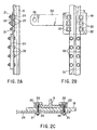
- FIGS. 1 to 3B show a first embodiment of the invention, in which FIG. 1 is a front view showing a winding device or a traction machine, FIGS. 2A to 2C are views showing a bracket mounting structure, and FIGS. 3A and 3B are schematic views showing an outline of a machine-room-less elevator.
- FIG. 3A there will be described the general construction of the elevator.
- a moving cage 2 and a counterweight 3 are suspended and balanced by means of a rope 4.
- Guide rails 5 and 6 for vertically guiding the moving cage 2 are arranged on the right- and left-hand sides, respectively, of the shaft 1, while counterweight guide rails 7 and 8 for guiding the counterweight 3 for up-and-down motion are arranged behind the left-hand guide rail 6.
- a drive unit 9 is set in a narrow space between an inner wall of the shaft 1 and a side wall of the moving cage 2.
- the drive unit 9, which is fixed to the guide rails 6 and 7, can wind up the rope 4, thereby relatively moving the cage 2 and the counterweight 3 up and down.
- one end portion of the rope 4, which is wound up by the drive unit 9, is fixed to a rope hitch 10 that is attached to the upper end portion of the guide rail 5, while the other end portion is fixed to a rope hitch 11 that is attached to the upper end portion of the counterweight guide rail 8.
- the middle portion of the rope 4 is passed around two lower sheaves 12 that are attached to the lower part of the moving cage 2, extends through the drive unit 9, and is then passed around a counterweight sheave 13 that is attached to the upper part of the counterweight 3.
- the two sheaves 12 are arranged along the direction parallel to a surface of a hall-door (not shown) of the elevator, the two sheaves 12 may be arranged along the direction inclined to the surface of the hall-door.
- emergency stop mechanisms 14 are provided on the bottom portion of the cage 2.
- the mechanisms 14 serve to stop the moving cage 2 safely and securely in case the cage suddenly descends at a speed higher than its rated speed for any reason.
- the mechanisms 14 brake and compulsorily stop the cage 2 in a manner such that wedge members, for example, are driven between the cage 2 and the guide rail 6.
- FIGS. 9A and 9B are enlarged schematic views showing one of the emergency stop mechanisms 14.
- the moving cage 2 is braked by driving a roller-shaped wedge member 51 between the guide rail 6 and a slope 50 on the cage side, as shown in FIG. 9B.
- the wedge member 51 is held by means of a holder 52 shown in FIG. 9A as it is moved to the position indicated by dashed line in FIG. 9B.
- the holder 52 is connected to a governor by means of a mechanism (not shown). If the moving cage 2 descends at a speed higher than a predetermined speed, the holder 52 is pulled up to actuate the emergency stop mechanism 14.
- the moving cage 2 In order to cancel an emergency stop state established by the emergency stop mechanism 14, the moving cage 2 must be compulsorily lifted to disengage the wedge member 51.
- FIG. 1 shows a chain block 18 for use as a winding device, which lifts the moving cage 2 in this manner, thereby releasing the emergency stop mechanism 14.
- the chain block 18 is suspended by a mounting member 17 that is attached to the guide rail 5 for positioning.
- the mounting member 17 includes a bracket 19, which is wider than the basal part of the guide rail 5 that has a substantially T-shaped cross section.
- the bracket 19 is bored with a plurality of bolt holes 20, which are arranged longitudinally at intervals a little longer than the width of the rail 5.
- Nuts 21 are provided on the back surface of the bracket 19, corresponding to the bolt holes 20, individually.
- a fitting hole 25 is formed in the distal end portion of the arm 24.
- the chain block 18 is suspended from the hole 25 by means of an upper hook 26.
- a lower hook 28 is provided on one end portion 27a of a chain 27 that is wound around the block 18, and is hitched to an anchor 29 on the ceiling of the moving cage 2.
- An operator M can pull up the one end portion 27a, to which the lower hook 28 is attached, by holding the other end portion 27b of the chain 27 and endlessly running the chain.
- FIG. 1 and FIGS. 2A to 2c there will be described a method for releasing the emergency stop mechanism 14, which is a feature of the present invention.
- the mechanism 14 When the mechanism 14 is activated so that the moving cage 2 is emergently stopped in the middle of the elevator shaft 1, the operator M gets on the ceiling of the cage 2 from a floor provided with an entrance, carrying the chain block 18 and the mounting member 17 with him. Then, the operator M presses the bracket 19 against the basal part of the guide rail 5 and inserts bolts 23, passed through the rail clips 22, into the bolt holes 20, individually, from the obverse side of the bracket 19.
- the guide rail 5 is an elongate structure formed by tying together a plurality of rails by means of joint plates 31 and bolts 32.
- the bracket 19 can be positioned by abutting the lower end face of the bracket 19 against upper end face of one of the joint plates 31. After the bracket 19 is mounted in place, moreover, it can be prevented from shifting its position downward.
- the chain block 18 is suspended by anchoring its upper hook 26 to the fitting hole 25 in the distal end portion of the arm 24, and the lower hook 28 is hitched to the anchor 29 of the moving cage 2. If the operator M endlessly runs the other end portion 27b of the chain 27 of the chain block 18 in this state, the lower hook 28 is wound up gradually, so that the cage 2 ascends gradually. As the cage 2 ascends in this manner, the emergency stop mechanism 14 is released. Thus, people confined to the moving cage 2, if any, can be rescued speedily.
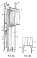
- FIGS. 4, 5A, 5B and 5C show a second embodiment of the invention.
- like reference numerals refer to the same components throughout the several views.
- An elevator according to this embodiment is of a type such that a moving cage 2 is suspended by means of a rope 4.
- the lower hook 28 of .the chain block 18 is attached to the anchor 29 that is provided on the ceiling of the moving cage 2.
- a rope gripper 33 is mounted on the rope 4 for suspending the moving cage 2, and the lower hook 28 is attached to the gripper 33.
- the rope gripper 33 is composed of two rectangular plate members 34 and 35 having a width greater than that of four rows of the rope 4.
- the gripper 33 can hold the four rows of the rope 4.
- the opposite surfaces of the plate members 34 and 35 are provided with fitting grooves 34a and 35a, respectively, in which the rope 4 is fitted.
- a plurality of bolts 36 are arranged penetrating those regions of the members 34 and 35 which face the spaces between the rope rows, and nuts 37 are fitted on the bolts 36, individually.
- a lug 38 protrudes integrally upward from the one plate member 34.
- a fitting hole 39 is bored through the lug 38.
- the rope gripper 33 can be attached to the rope 4 with the four rows of the rope 4 held between the two plate members 34 and 35 and clamped by means of the bolts 3 and the nuts 37. Further, the moving cage 2 can be raised by means of the rope 4 to release the emergency stop mechanism 14 in a manner such that the lower hook 28 of the chain block 18 is anchored to the fitting hole 39 of the gripper 33.
- the moving cage 2 can be lifted steadily without being tilted, and the rope gripper 33 can be mounted in any desired position on the rope 4.
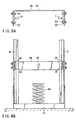
- FIG. 6 shows a third embodiment of the invention.
- like reference numerals refer to the same components throughout the several views.
- the emergency stop state is canceled by directly hoisting the moving cage 2.
- a moving cage 2 is driven by driving a counterweight 3.
- a chain block 18 for use as a winding device is attached to a suspension base of a pit 1a of the elevator shaft 1 and a suspension base of the counterweight 3.
- the moving cage 2 is lifted to release the emergency stop mechanism 14 by lowering the counterweight 3 by means of the chain block 18.
- a bracket 40 is attached by means of a plurality of bolts 41 to the lower part of the counterweight 3 that is supported by counterweight guide rails 7 and 8 for up-and-down motion.
- the bracket 40 can ascend and descend integrally with the counterweight 3.
- a lug 42 protrudes downward from the crosswise middle portion of the bracket 40.
- a fitting hole 43 is bored through the lug 42.
- An upper hook 26 of the chain block 18 is anchored to the fitting hole 43 so that the block 18 is suspended from the hole 43.
- a lower hook 28 on one end portion 27a of a chain 27 of the chain block 18 is hitched to an anchor 44 in the pit 1a of the elevator shaft 1.
- the shaft pit 1a is provided with a buffer 45 formed of a coil spring that can absorb the shock of dropping of the counterweight 3.
- the moving cage 2 In the case where the moving cage 2 is located near the uppermost floor, it is hard for the operator M to get on its ceiling. With use of the arrangement described above, in this case, the operator M can get into the shaft pit 1a, anchor the upper hook 26 of the chain block 18 to the fitting hole 43 of the bracket 40 to suspend the block 18, and hitch the lower hook 28 to the anchor 44 of the shaft pit la. If the operator M endlessly runs the other end portion 27b of the chain 27 in this state, the one end portion 27a of the chain 27 is wound up gradually, so that the counterweight 3 descends, while the moving cage 2 ascends gradually. As the cage 2 ascends in this manner, the emergency stop mechanism 14 is released. Thus, people confined to the moving cage 2, if any, can be rescued speedily.
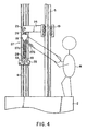
- FIGS. 7, 8A and 8B show a fourth embodiment of the invention.
- like reference numerals refer to the same components throughout the several views.
- a chain block 18 for use as a winding device is attached to a suspension base at the respective lower parts of counterweight guide rails 7 and 8 and a suspension base of a counterweight 3.
- a moving cage 2 is lifted to release the emergency stop mechanism 14 by lowering the counterweight 3 by means of the chain block 18.
- a bracket 46 is located corresponding to those portions of the counterweight guide rails 7 and 8 which are located below the counterweight 3.
- the bracket 46 is attached to the rails 7 and 8 by means of rail clips 22 similar to the ones according to the first embodiment.
- a fitting hole 47 is bored through the longitudinal middle portion of the bracket 46.
- An upper hook 26 of the chain block 18 is anchored to a fitting hole 43 of a lug 42 so that the block 18 is suspended from the hole 43.
- a lower hook 28 on one end portion 27a of a chain 27 of the chain block 18 is hitched to the fitting hole 47 of the bracket 46 that is attached to the counterweight guide rails 7 and 8.
- the operator M can get into a shaft pit 1a, anchor the upper hook 26 of the chain block 18 to the fitting hole 43 of the lug 42 to suspend the block 18, and hitch the lower hook 28 to the fitting hole 47 of the bracket 46. If the operator M endlessly runs the other end portion 27b of the chain 27 in this state, the one end portion 27a of the chain 27 is wound up gradually, so that the counterweight 3 descends, while the moving cage 2 ascends gradually. As the cage 2 ascends in this manner, the emergency stop mechanism 14 is released. Thus, people confined to the moving cage 2, if any, can be rescued speedily.
Applications Claiming Priority (2)
| Application Number | Priority Date | Filing Date | Title |
|---|---|---|---|
| JP25112398 | 1998-09-04 | ||
| JP10251123A JP2000086109A (ja) | 1998-09-04 | 1998-09-04 | エレベータの非常停止装置解除方法 |
Publications (3)
| Publication Number | Publication Date |
|---|---|
| EP0983956A2 EP0983956A2 (en) | 2000-03-08 |
| EP0983956A3 EP0983956A3 (en) | 2002-03-20 |
| EP0983956B1 true EP0983956B1 (en) | 2003-12-10 |
Family
ID=17218018
Family Applications (1)
| Application Number | Title | Priority Date | Filing Date |
|---|---|---|---|
| EP99103916A Expired - Lifetime EP0983956B1 (en) | 1998-09-04 | 1999-03-05 | Emergency stop device releasing method for elevator |
Country Status (7)
| Country | Link |
|---|---|
| US (1) | US6119816A (ko) |
| EP (1) | EP0983956B1 (ko) |
| JP (1) | JP2000086109A (ko) |
| KR (1) | KR100287469B1 (ko) |
| CN (1) | CN1093501C (ko) |
| DE (1) | DE69913445T2 (ko) |
| MY (1) | MY123299A (ko) |
Cited By (2)
| Publication number | Priority date | Publication date | Assignee | Title |
|---|---|---|---|---|
| CN107601204A (zh) * | 2017-10-19 | 2018-01-19 | 中联重科股份有限公司 | 升降机 |
| WO2021036398A1 (zh) * | 2019-08-27 | 2021-03-04 | 森赫电梯股份有限公司 | 一种夹轨式无机房电梯救援装置及方法 |
Families Citing this family (11)
| Publication number | Priority date | Publication date | Assignee | Title |
|---|---|---|---|---|
| FR2822816A1 (fr) * | 2001-03-30 | 2002-10-04 | Nk System Nv | Dispositif de deblocage de secours pour ascenseurs hydrauliques |
| JP5000106B2 (ja) | 2004-07-07 | 2012-08-15 | インベンテイオ・アクテイエンゲゼルシヤフト | エレベータ設備を移動させる装置 |
| EP1621506B1 (en) * | 2004-07-07 | 2017-09-13 | Inventio AG | Apparatus for moving elevator equipment |
| EP1669315A1 (de) * | 2004-12-13 | 2006-06-14 | Inventio Ag | Verfahren und Hilfsantriebseinrichtung zum Antreiben einer Aufzugskabine |
| CN101927929B (zh) * | 2004-12-15 | 2012-10-17 | 三菱电机株式会社 | 电梯紧急停止装置 |
| DE102009048522A1 (de) * | 2009-09-29 | 2011-03-31 | Aufzugswerke M. Schmitt & Sohn Gmbh & Co. | Aushebevorrichtung für Aufzüge |
| FR2962722B1 (fr) * | 2010-07-15 | 2012-07-13 | Octe | Dispositif de deprise, pour le deblocage d'un ascenseur apres fonctionnement du parachute en montee |
| JP5539268B2 (ja) * | 2011-06-22 | 2014-07-02 | 株式会社日立製作所 | ダブルデッキエレベーターのかご用非常止め復帰方法 |
| ES2565013B2 (es) * | 2015-12-23 | 2017-02-08 | Mac Puar, S.A. | Dispositivo para el desbloqueo de paracaídas de un ascensor |
| CN108928704A (zh) * | 2017-05-22 | 2018-12-04 | 蒂森克虏伯电梯(上海)有限公司 | 电梯救援方法 |
| CN112193963A (zh) * | 2020-09-30 | 2021-01-08 | 宁波宏大电梯有限公司 | 一种安全钳复位装置、电梯及安全钳复位方法 |
Family Cites Families (16)
| Publication number | Priority date | Publication date | Assignee | Title |
|---|---|---|---|---|
| US3469657A (en) * | 1966-05-09 | 1969-09-30 | Salvatore Sgroi | Automatic emergency relevelling device for lifts |
| US3706357A (en) * | 1970-03-30 | 1972-12-19 | Joseph Elmer Simpson | Elevator emergency actuator and rescue unit |
| IT1144355B (it) * | 1981-05-12 | 1986-10-29 | Sergio Scarzella | Sistema di emergenza per ascensori e simili per il salvataggio autonomo dell utente bloccato in cabina |
| US4529066A (en) * | 1982-04-28 | 1985-07-16 | Harnischfeger Corporation | Safety brake for mast-type crane |
| JPH01236188A (ja) * | 1988-03-14 | 1989-09-21 | Mitsubishi Electric Corp | エレベータ |
| JPH02270792A (ja) * | 1989-04-11 | 1990-11-05 | Toshiba Corp | エレベータのターニングハンドル機構 |
| JPH0336185A (ja) * | 1989-06-30 | 1991-02-15 | Toshiba Corp | リニアモータエレベータ |
| JPH0665587B2 (ja) * | 1990-04-13 | 1994-08-24 | 寺岡エンタープライズ株式会社 | エレベータの非常時脱出装置 |
| US5202539A (en) * | 1991-08-28 | 1993-04-13 | Inventio Ag | Emergency brake apparatus for an elevator |
| JPH05105361A (ja) * | 1991-10-18 | 1993-04-27 | Hitachi Building Syst Eng & Service Co Ltd | エレベータのガイドレール |
| JPH05186159A (ja) * | 1992-01-13 | 1993-07-27 | Hitachi Building Syst Eng & Service Co Ltd | エレベータの主ロープ交換方法 |
| JPH05229766A (ja) * | 1992-02-18 | 1993-09-07 | Hitachi Building Syst Eng & Service Co Ltd | エレベーターの昇降体固定装置 |
| JP2849288B2 (ja) * | 1992-09-03 | 1999-01-20 | 株式会社日立ビルシステム | エレベータの主索牽引装置 |
| FI94123C (fi) * | 1993-06-28 | 1995-07-25 | Kone Oy | Vetopyörähissi |
| JPH0899780A (ja) * | 1994-09-30 | 1996-04-16 | Mitsubishi Denki Bill Techno Service Kk | ロープ式リニアモータエレベーター |
| TW348169B (en) * | 1994-11-15 | 1998-12-21 | Inventio Ag | Evacuation system for a lift cage |
-
1998
- 1998-09-04 JP JP10251123A patent/JP2000086109A/ja active Pending
-
1999
- 1999-02-25 KR KR1019990006322A patent/KR100287469B1/ko not_active IP Right Cessation
- 1999-03-01 CN CN99100861A patent/CN1093501C/zh not_active Expired - Fee Related
- 1999-03-05 EP EP99103916A patent/EP0983956B1/en not_active Expired - Lifetime
- 1999-03-05 DE DE69913445T patent/DE69913445T2/de not_active Expired - Fee Related
- 1999-08-21 MY MYPI99003596A patent/MY123299A/en unknown
- 1999-09-07 US US09/390,659 patent/US6119816A/en not_active Expired - Fee Related
Cited By (2)
| Publication number | Priority date | Publication date | Assignee | Title |
|---|---|---|---|---|
| CN107601204A (zh) * | 2017-10-19 | 2018-01-19 | 中联重科股份有限公司 | 升降机 |
| WO2021036398A1 (zh) * | 2019-08-27 | 2021-03-04 | 森赫电梯股份有限公司 | 一种夹轨式无机房电梯救援装置及方法 |
Also Published As
| Publication number | Publication date |
|---|---|
| CN1093501C (zh) | 2002-10-30 |
| JP2000086109A (ja) | 2000-03-28 |
| US6119816A (en) | 2000-09-19 |
| MY123299A (en) | 2006-05-31 |
| KR100287469B1 (ko) | 2001-04-16 |
| EP0983956A2 (en) | 2000-03-08 |
| KR20000022577A (ko) | 2000-04-25 |
| CN1247154A (zh) | 2000-03-15 |
| DE69913445T2 (de) | 2004-10-28 |
| EP0983956A3 (en) | 2002-03-20 |
| DE69913445D1 (de) | 2004-01-22 |
Similar Documents
| Publication | Publication Date | Title |
|---|---|---|
| EP0983956B1 (en) | Emergency stop device releasing method for elevator | |
| EP0990615B1 (en) | Elevator with governor | |
| KR102308534B1 (ko) | 기계실이 필요없는 로프식 자체구동 엘리베이터 | |
| JP4550830B2 (ja) | エレベータ | |
| JP2000086109A5 (ko) | ||
| JP2011006218A (ja) | エレベーターの乗客救出装置 | |
| JP3413868B2 (ja) | リニアモータ駆動方式エレベータ装置 | |
| JP3961895B2 (ja) | エレベータの閉じ込め救出方法および装置 | |
| JP2001192190A (ja) | エレベーター装置 | |
| JP2001097648A (ja) | エレベータの乗客救出方法 | |
| JP2000169055A5 (ko) | ||
| JPH07237847A (ja) | エレベーターの据付工法 | |
| JP3353032B2 (ja) | エレベータ | |
| JP2000169055A (ja) | エレベータの乗客救出方法 | |
| JP3528840B2 (ja) | 機械室レスエレベータ装置 | |
| JP2005280956A (ja) | エレベータの閉じ込め救出装置 | |
| US20230042428A1 (en) | Lifting device for lifting a payload within an elevator shaft in a controllable manner | |
| JP3438697B2 (ja) | 機械室レスエレベータ装置 | |
| JP2502323Y2 (ja) | 工事用エレベ―タ | |
| JP2001247271A (ja) | エレベータのつり合いおもり引揚げ装置。 | |
| WO2023160819A1 (en) | An elevator construction arrangement and a method | |
| JP3888513B2 (ja) | 2対1ローピングエレベータの主ロープ端部調整方法 | |
| JPH08245130A (ja) | リニアモータ式エレベータ | |
| JP2003040555A (ja) | 機械室レスエレベータ装置 | |
| JPS586886A (ja) | エレベ−タ装置 |
Legal Events
| Date | Code | Title | Description |
|---|---|---|---|
| PUAI | Public reference made under article 153(3) epc to a published international application that has entered the european phase |
Free format text: ORIGINAL CODE: 0009012 |
|
| 17P | Request for examination filed |
Effective date: 19990305 |
|
| AK | Designated contracting states |
Kind code of ref document: A2 Designated state(s): AT BE CH CY DE DK ES FI FR GB GR IE IT LI LU MC NL PT SE Kind code of ref document: A2 Designated state(s): CH DE FI LI |
|
| AX | Request for extension of the european patent |
Free format text: AL;LT;LV;MK;RO;SI |
|
| PUAL | Search report despatched |
Free format text: ORIGINAL CODE: 0009013 |
|
| AK | Designated contracting states |
Kind code of ref document: A3 Designated state(s): AT BE CH CY DE DK ES FI FR GB GR IE IT LI LU MC NL PT SE |
|
| AX | Request for extension of the european patent |
Free format text: AL;LT;LV;MK;RO;SI |
|
| AKX | Designation fees paid |
Free format text: CH DE FI LI |
|
| 17Q | First examination report despatched |
Effective date: 20021213 |
|
| GRAH | Despatch of communication of intention to grant a patent |
Free format text: ORIGINAL CODE: EPIDOS IGRA |
|
| GRAS | Grant fee paid |
Free format text: ORIGINAL CODE: EPIDOSNIGR3 |
|
| GRAA | (expected) grant |
Free format text: ORIGINAL CODE: 0009210 |
|
| AK | Designated contracting states |
Kind code of ref document: B1 Designated state(s): CH DE FI LI |
|
| REG | Reference to a national code |
Ref country code: CH Ref legal event code: EP |
|
| REG | Reference to a national code |
Ref country code: IE Ref legal event code: FG4D |
|
| REF | Corresponds to: |
Ref document number: 69913445 Country of ref document: DE Date of ref document: 20040122 Kind code of ref document: P |
|
| REG | Reference to a national code |
Ref country code: CH Ref legal event code: NV Representative=s name: E. BLUM & CO. PATENTANWAELTE |
|
| PLBE | No opposition filed within time limit |
Free format text: ORIGINAL CODE: 0009261 |
|
| STAA | Information on the status of an ep patent application or granted ep patent |
Free format text: STATUS: NO OPPOSITION FILED WITHIN TIME LIMIT |
|
| 26N | No opposition filed |
Effective date: 20040913 |
|
| REG | Reference to a national code |
Ref country code: IE Ref legal event code: MM4A |
|
| PGFP | Annual fee paid to national office [announced via postgrant information from national office to epo] |
Ref country code: DE Payment date: 20070301 Year of fee payment: 9 Ref country code: CH Payment date: 20070301 Year of fee payment: 9 |
|
| PGFP | Annual fee paid to national office [announced via postgrant information from national office to epo] |
Ref country code: FI Payment date: 20070314 Year of fee payment: 9 |
|
| REG | Reference to a national code |
Ref country code: CH Ref legal event code: PFA Owner name: KABUSHIKI KAISHA TOSHIBA Free format text: KABUSHIKI KAISHA TOSHIBA#72, HORIKAWA-CHO, SAIWAI-KU#KAWASAKI-SHI, KANAGAWA 212-8572 (JP) -TRANSFER TO- KABUSHIKI KAISHA TOSHIBA#72, HORIKAWA-CHO, SAIWAI-KU#KAWASAKI-SHI, KANAGAWA 212-8572 (JP) |
|
| PG25 | Lapsed in a contracting state [announced via postgrant information from national office to epo] |
Ref country code: FI Free format text: LAPSE BECAUSE OF NON-PAYMENT OF DUE FEES Effective date: 20080305 |
|
| REG | Reference to a national code |
Ref country code: CH Ref legal event code: PL |
|
| PG25 | Lapsed in a contracting state [announced via postgrant information from national office to epo] |
Ref country code: LI Free format text: LAPSE BECAUSE OF NON-PAYMENT OF DUE FEES Effective date: 20080331 Ref country code: DE Free format text: LAPSE BECAUSE OF NON-PAYMENT OF DUE FEES Effective date: 20081001 Ref country code: CH Free format text: LAPSE BECAUSE OF NON-PAYMENT OF DUE FEES Effective date: 20080331 |