EP0977244B1 - Système de support et procédé de commande du support pour l'utilisation dans un appareil d'exposition - Google Patents
Système de support et procédé de commande du support pour l'utilisation dans un appareil d'exposition Download PDFInfo
- Publication number
- EP0977244B1 EP0977244B1 EP99306002A EP99306002A EP0977244B1 EP 0977244 B1 EP0977244 B1 EP 0977244B1 EP 99306002 A EP99306002 A EP 99306002A EP 99306002 A EP99306002 A EP 99306002A EP 0977244 B1 EP0977244 B1 EP 0977244B1
- Authority
- EP
- European Patent Office
- Prior art keywords
- stage
- unit
- force
- linear motor
- electromagnet
- Prior art date
- Legal status (The legal status is an assumption and is not a legal conclusion. Google has not performed a legal analysis and makes no representation as to the accuracy of the status listed.)
- Expired - Lifetime
Links
- 238000000034 method Methods 0.000 title claims description 34
- 230000001133 acceleration Effects 0.000 claims description 106
- 230000033001 locomotion Effects 0.000 claims description 67
- 230000005484 gravity Effects 0.000 claims description 37
- 238000004519 manufacturing process Methods 0.000 claims description 8
- 230000003287 optical effect Effects 0.000 claims description 5
- 239000000463 material Substances 0.000 claims description 4
- 239000000696 magnetic material Substances 0.000 description 84
- 230000020169 heat generation Effects 0.000 description 39
- 238000005259 measurement Methods 0.000 description 30
- 208000006011 Stroke Diseases 0.000 description 23
- 230000009471 action Effects 0.000 description 22
- 230000004044 response Effects 0.000 description 20
- 230000008569 process Effects 0.000 description 19
- 230000006870 function Effects 0.000 description 18
- 230000007246 mechanism Effects 0.000 description 11
- 238000010586 diagram Methods 0.000 description 8
- 239000004065 semiconductor Substances 0.000 description 7
- 230000008859 change Effects 0.000 description 5
- 238000009825 accumulation Methods 0.000 description 4
- 230000008901 benefit Effects 0.000 description 4
- 230000000694 effects Effects 0.000 description 4
- 238000006073 displacement reaction Methods 0.000 description 3
- 230000004907 flux Effects 0.000 description 3
- 230000003993 interaction Effects 0.000 description 3
- XEEYBQQBJWHFJM-UHFFFAOYSA-N Iron Chemical compound [Fe] XEEYBQQBJWHFJM-UHFFFAOYSA-N 0.000 description 2
- 238000006243 chemical reaction Methods 0.000 description 2
- 230000007423 decrease Effects 0.000 description 2
- 238000005530 etching Methods 0.000 description 2
- 238000007689 inspection Methods 0.000 description 2
- 150000002500 ions Chemical class 0.000 description 2
- 230000006641 stabilisation Effects 0.000 description 2
- 238000011105 stabilization Methods 0.000 description 2
- 238000013519 translation Methods 0.000 description 2
- 230000005540 biological transmission Effects 0.000 description 1
- 230000015556 catabolic process Effects 0.000 description 1
- 238000001444 catalytic combustion detection Methods 0.000 description 1
- 230000008602 contraction Effects 0.000 description 1
- 238000006731 degradation reaction Methods 0.000 description 1
- 238000013461 design Methods 0.000 description 1
- 238000012938 design process Methods 0.000 description 1
- 238000011161 development Methods 0.000 description 1
- 238000005286 illumination Methods 0.000 description 1
- 230000002452 interceptive effect Effects 0.000 description 1
- 229910052742 iron Inorganic materials 0.000 description 1
- 238000010030 laminating Methods 0.000 description 1
- 239000004973 liquid crystal related substance Substances 0.000 description 1
- 238000001459 lithography Methods 0.000 description 1
- 238000012986 modification Methods 0.000 description 1
- 230000004048 modification Effects 0.000 description 1
- 230000007659 motor function Effects 0.000 description 1
- 230000003647 oxidation Effects 0.000 description 1
- 238000007254 oxidation reaction Methods 0.000 description 1
- 230000001590 oxidative effect Effects 0.000 description 1
- 238000004806 packaging method and process Methods 0.000 description 1
- 230000009467 reduction Effects 0.000 description 1
- 238000007789 sealing Methods 0.000 description 1
- 238000000926 separation method Methods 0.000 description 1
- 229910052710 silicon Inorganic materials 0.000 description 1
- 239000010703 silicon Substances 0.000 description 1
- 238000007740 vapor deposition Methods 0.000 description 1
Images


Classifications
-
- G—PHYSICS
- G03—PHOTOGRAPHY; CINEMATOGRAPHY; ANALOGOUS TECHNIQUES USING WAVES OTHER THAN OPTICAL WAVES; ELECTROGRAPHY; HOLOGRAPHY
- G03F—PHOTOMECHANICAL PRODUCTION OF TEXTURED OR PATTERNED SURFACES, e.g. FOR PRINTING, FOR PROCESSING OF SEMICONDUCTOR DEVICES; MATERIALS THEREFOR; ORIGINALS THEREFOR; APPARATUS SPECIALLY ADAPTED THEREFOR
- G03F7/00—Photomechanical, e.g. photolithographic, production of textured or patterned surfaces, e.g. printing surfaces; Materials therefor, e.g. comprising photoresists; Apparatus specially adapted therefor
- G03F7/20—Exposure; Apparatus therefor
-
- H—ELECTRICITY
- H01—ELECTRIC ELEMENTS
- H01L—SEMICONDUCTOR DEVICES NOT COVERED BY CLASS H10
- H01L21/00—Processes or apparatus adapted for the manufacture or treatment of semiconductor or solid state devices or of parts thereof
- H01L21/67—Apparatus specially adapted for handling semiconductor or electric solid state devices during manufacture or treatment thereof; Apparatus specially adapted for handling wafers during manufacture or treatment of semiconductor or electric solid state devices or components ; Apparatus not specifically provided for elsewhere
- H01L21/67005—Apparatus not specifically provided for elsewhere
- H01L21/67242—Apparatus for monitoring, sorting or marking
-
- G—PHYSICS
- G03—PHOTOGRAPHY; CINEMATOGRAPHY; ANALOGOUS TECHNIQUES USING WAVES OTHER THAN OPTICAL WAVES; ELECTROGRAPHY; HOLOGRAPHY
- G03F—PHOTOMECHANICAL PRODUCTION OF TEXTURED OR PATTERNED SURFACES, e.g. FOR PRINTING, FOR PROCESSING OF SEMICONDUCTOR DEVICES; MATERIALS THEREFOR; ORIGINALS THEREFOR; APPARATUS SPECIALLY ADAPTED THEREFOR
- G03F7/00—Photomechanical, e.g. photolithographic, production of textured or patterned surfaces, e.g. printing surfaces; Materials therefor, e.g. comprising photoresists; Apparatus specially adapted therefor
- G03F7/70—Microphotolithographic exposure; Apparatus therefor
- G03F7/70691—Handling of masks or workpieces
- G03F7/70716—Stages
- G03F7/70725—Stages control
-
- H—ELECTRICITY
- H01—ELECTRIC ELEMENTS
- H01L—SEMICONDUCTOR DEVICES NOT COVERED BY CLASS H10
- H01L21/00—Processes or apparatus adapted for the manufacture or treatment of semiconductor or solid state devices or of parts thereof
- H01L21/67—Apparatus specially adapted for handling semiconductor or electric solid state devices during manufacture or treatment thereof; Apparatus specially adapted for handling wafers during manufacture or treatment of semiconductor or electric solid state devices or components ; Apparatus not specifically provided for elsewhere
- H01L21/68—Apparatus specially adapted for handling semiconductor or electric solid state devices during manufacture or treatment thereof; Apparatus specially adapted for handling wafers during manufacture or treatment of semiconductor or electric solid state devices or components ; Apparatus not specifically provided for elsewhere for positioning, orientation or alignment
Definitions
- This invention relates generally to a stage system in which high precision positioning performance is required.
- the invention relates also to an exposure apparatus having such stage system for carrying a reticle or a wafer thereon for exposure of the same, and to a device manufacturing method using such exposure apparatus.
- the invention relates to a stage driving method effective to perform high precision positioning.
- FIGS 15A and 15B are schematic views of an example of known type stage system.
- a guide 802 is fixed to a base (not shown), and a stage 801 for carrying a workpiece 800 thereon is supported by the guide 802 slidably along one axial direction relative to it.
- the linear motor stators 805 are fixed to the base, not shown.
- Each linear motor moving element 804 comprises upper and lower integral structures of four-pole magnets 804a and yokes 804b for circulation of magnetic fluxes of the magnets.
- Each linear motor stator 805 comprises a plurality of coils 805a (six in this example) disposed in an array and being fixed together by a stator frame 805b.
- the linear motor 803 described above is an extended type of ordinary brushless DC motor, wherein the driving coil and the direction of electric current thereto are changed in accordance with the relative positional relationship between the magnet 804a and the coil 805a, whereby a desired force is produced in a desired direction.
- an electric current is applied to predetermined linear motor coils in a predetermined direction and for a predetermined time period in accordance with the position of the stage 801 or of the magnets 804a, to produce acceleration of the stage 801.
- a predetermined operation such as exposure or inspection, for example, is performed.
- an electric current is applied to predetermined linear motor coils in a predetermined direction and for a predetermined time period, to cause deceleration of the stage and to stop the stage motion.
- the position of the stage is measured by using high precision position sensor means (not shown) such as a laser interferometer, for example, and an electric current is applied to linear motor coils separately from acceleration or deceleration, so as to avoid an error with respect to a target position.
- high precision position sensor means such as a laser interferometer, for example, and an electric current is applied to linear motor coils separately from acceleration or deceleration, so as to avoid an error with respect to a target position.
- FIG 16 is a schematic view of another example of known type stage system.
- This stage system is similar to one disclosed in Japanese Laid-Open Patent Application, Laid-Open No. 183192/1995 .
- a guide 909 is mounted on a base 903, and a stage 907 is supported slidably relative to the guide 909.
- the base 903 is provided with an actuator unit 901 which serves to perform the positioning through expansion and contraction of its rod 905.
- Disposed between an end of the rod 905 and the stage 907 are a voice coil motor 906 and a clutch 904.
- the motor 906 comprises a coil-and-magnet structure (not shown), and a Lorentz force is produced in response to application of electric current to the coil, whereby a driving force is produced between the rod 905 and the stage 907.
- the clutch 904 for driving the stage, first the clutch 904 is engaged through mechanical contact so that the rod 905 and the stage are held in connection. The driving force of the actuator unit 901 is thus transmitted to the stage, whereby rough motion of the stage is produced. The clutch 904 is disengaged after the stage rough motion, and the stage 907 is driven thereafter relative to the rod 905 with the driving force of the voice coil motor 906, to accomplish the positioning of the stage 907.
- stage system wherein a voice coil motor and a clutch are provided in parallel between an actuator unit and a stage
- the voice coil motor since the clutch is held in engagement during the stage motion through the actuator unit, the voice coil motor is inoperative. In the rough motion period of the actuator unit, therefore, deviations to the stage target position may be accumulated, which means prolongation of positioning time required for the voice coil motor. Further, since the clutch is based on mechanical contact such as friction, there is a limit to stage precise positioning.
- the voice coil motor If the voice coil motor is operated while disengaging the clutch, in actuation of the actuator unit, the voice coil motor has to produce a large thrust force which causes large heat generation and lowered stage positioning precision.
- the stator of the motor must be positioned very precisely with respect to the moving element provided on the stage. In that case, the positioning of the rod by the actuator unit has to be performed vary precisely.
- the rod positioning control through the actuator unit is based on the current position of the stage as measured by the laser interferometer, it is very difficult to accomplish high precision positioning for the rod.
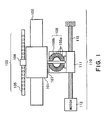
- Figure 1 is a schematic view of a stage system according to a first example
- a guide 102 is fixed to a base (not shown), and a stage 101 for carrying a workpiece thereon is supported by the guide 102 reciprocally slidably along one axial direction (predetermined direction) relative to it.
- a linear motor moving element 104 fixedly mounted at one side of the stage 101.
- the moving element 104 faces to a linear motor stator 105 without contact thereto.
- the linear motor stator 105 is fixed to the base, not shown.
- a linear motor 103 may have a similar mechanism as that of the example described hereinbefore, but it may be of small output type as compared with the described example.
- the linear motor is provided with a control system having a hardware or software current limiting system, so that flow of large electric current causing large heat generation is prevented. Additionally, as long as the control system operates normally, there is no flow of electric current causing such heat generation, regardless of the provision of the limiting system (this will be described later).
- a magnetic material plate 107 is provided on the other side of the stage 101.
- the electromagnets 108 are held fixed by using a nut 111.
- the nut 111 can be moved substantially in the same direction as the stage 101, by means of a motor 112 and a feed screw 113.
- the feed screw system 10 having nut 111, motor 112 and feed screw 113, the paired electromagnets 108 can be moved substantially in the same direction as the stage 101.
- the feed screw system 110 (moving mechanism) for moving the electromagnets 108 is fixed to the unshown base.
- Each electromagnet 108 of the paired electromagnets and the magnetic material plate 107 are held out of contact with each other, with a small clearance.
- Each electromagnet 108 comprises a yoke 108b of arcuate shape and a coil 108a wound around it. When electric current is flown through the coil 108a, an attraction force is produced between the yoke 108b and the magnetic material plate 107.
- the flows of electric currents to the coils 108a of the electromagnets 108 can be controlled independently of each other.
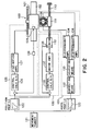
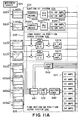
- Figure 2 is a block diagram of a control system for drive controlling the stage system. It comprises movement target specifying means 121 for creating a movement target for the stage 101, position profile producing means 122 for generating the relationship between the time and the stage target position corresponding to that time, on the basis of the created target, and acceleration profile producing means 123 for generating the relationship between the time and the acceleration to be provided during that time, on the basis of the created target.
- movement target specifying means 121 for creating a movement target for the stage 101
- position profile producing means 122 for generating the relationship between the time and the stage target position corresponding to that time, on the basis of the created target
- acceleration profile producing means 123 for generating the relationship between the time and the acceleration to be provided during that time, on the basis of the created target.
- the output of the position profile producing means 122 is applied to a fine-motion linear motor position servo system 125 for controlling a fine-motion linear motor 103 and to a movement feedback (FB) system 135 for feedback controlling the motor 112 of the feed screw system 110.
- the output of the acceleration profile producing means 123 is applied to an attraction feed-forward (FF) system 131 for feed-forward controlling the attraction force of the electromagnet 108.
- FF attraction feed-forward
- the fine-motion linear motor position servo system 125 comprises calculating means 126, a motor current amplifier 127, a linear motor 103 and an interferometer 128.
- the calculating means 126 operates to perform control calculation, typically such as PID, for example, to a difference between a current target position of the stage as specified by the position profile producing means 122 and the current position of the stage 101 as measured by the interferometer 128. The result of calculation is applied, in analog voltage, to the amplifier 127.
- the motor current amplifier 127 is a fine-motion current amplifier for supplying an electric current, proportional to the produced analog output voltage, to the linear motor.
- the linear motor 103 has a structure such as described above, and, in response to the supplied current, it applies thrust to the stage 101.
- the interferometer 128 serves to measure the position of a reflection mirror 129 mounted on the stage 101, and thus to measure the position of the stage (or a moving element provided integrally with the stage).
- the fine-motion linear motor position servo system 125 is an ordinary position servo system which is operable while using the output of the position profile producing means 122 as a designation signal.
- the attraction feed-forward (FF) system 131 operates to produce the thrust.
- the linear motor 103 is required to produce only small thrust necessary for removing a positional error with respect to the target position. Therefore, there is no flow of electric current that may cause large heat generation. Additionally, the flow of electric current is limited by hardware or software, such that, even if the operational association with the attraction feed-forward (FF) system 131 is out of order, flow of electric current causing serious heat generation can be prevented.
- the attraction feed-forward (FF) system 131 is a control system for producing combined thrust between the magnetic material plate 107 and the paired electromagnets 108, which thrust is proportional to the output of the acceleration profile producing means 123.
- the attraction FF system 131 comprises correcting means 132, adjusting means 133 and two electromagnet current amplifiers 134.
- the electromagnet current amplifiers 134 serve to energize the coils 108a of the electromagnets 108, independently of each other.
- the correcting means 132 functions to correct non-linear relationship between the electric current and attraction force of the electromagnet 108, and it includes a square root calculator.
- the attraction force of an electromagnet is proportional to a square of the electric current to the electromagnet.
- the attraction force to be produced to drive the stage 101 is a force which is proportional to the output of the acceleration profile producing means. Therefore, once the square root of the output of the acceleration profile producing means 123 is detected and it is taken as a designating signal, an attraction force proportional to the square of the square root of the output of the acceleration profile producing means 123 can be produced. Also, since the sign of the output of the acceleration profile producing means 123 may be either positive or negative, the square root calculation may be made to an absolute value of the output and, after the calculation, the sign may be specified when the result is applied to the adjusting means.
- the adjusting means 133 serves to adjust attraction forces functioning between the paired electromagnets 108 and the magnetic material plate 107, so that these forces are combined into a force of desired magnitude and orientation. Regardless of the direction of electric current, the electromagnet can produce only a force for attracting the magnetic material plate. In consideration of it, a pair of electromagnets are placed to sandwich the magnetic material plate therebetween, so that these electromagnets produce and apply opposite forces to the magnetic material plate. By adjusting these two forces, the magnitude and orientation of a combined force acting on the magnetic material plate is controlled.
- One convenient control procedure may be that: in accordance with the sign of the output of the correcting means 132 described above, one of the paired electromagnets to which the electric current is to be applied is selected, and a value proportional to the output of the correcting means 132 is applied to the current amplifier 134 while the electric current to the other electromagnet 108 is kept null. If the output of the correcting means 132 is null, the electric current to both electromagnets is controlled to null. As a result of this, a thrust which is proportional to the output of the acceleration profile producing means 123 is applied from the paired electromagnets 108 to the magnetic material plate 107, in a desired direction.
- Bias electric currents of the same level may be applied to the two electromagnets 108 when the output of the correcting means 132 is null.
- This provides an effect that the relation between the current and the operation center of BH curve of the electromagnet, that is, the relation between the strength of magnetic field and the magnetic density becomes more linear.
- the correcting means 132 and the adjusting means 133 may function integrally to designate, in response to the output of the acceleration profile 123, appropriate currents for the two electromagnets.
- the output of the acceleration profile producing means in the positive movement direction is Va
- the bias current is Ib
- the electromagnet coil current for producing an attraction force in the positive movement direction is Ip
- the electromagnet coil current for producing an attraction force in the negative movement direction is Im
- the attraction force of an electromagnet can produce large thrust with a small ampere-turn as compared with the Lorentz force of a linear motor.
- heat generation of electromagnet is very small and it does not cause any inconvenience.
- the movement feedback (FB) system 135 functions to cause the positions of the pair of electromagnets 108 to move and follow the position profile. While an electromagnet has an advantage that a large attraction force is produced with small heat generation, the clearance to a magnetic material opposed to it should be kept small. In order to assure that a desired force is continuously applied from the electromagnet 108 to the magnetic material plate 107 and then to the stage 101, the electromagnet 108 should be moved in accordance with the motion of the stage 101 so that the clearance is maintained constant.
- position profile is inputted into the position control system 135 which serves to feed back the position of the electromagnet 108 through an encoder 138 of the motor 112, such that the electromagnet 108 is moved by means of the motor 112 and the feed screw 113 to follow the position profile substantially the same as of the stage 101.
- the relative position of the electromagnet 108 and the stage 101 can be held substantially constant.
- the motor 112 should produce a torque corresponding to the combined force of attraction forces produced by the electromagnets 108 during acceleration or deceleration of the stage 101, in addition to a torque necessary for the acceleration or deceleration of the electromagnet 108 and the nut 111 of the screw system 110. This is because the attraction force applied to the stage is also transmitted to the nut through the electromagnet.
- the output of the acceleration profile producing means 123 may be added to the output of the control calculator and the sum may be inputted into the motor current amplifier 137. This enables designation of acceleration to the motor 112 like feed-forward control, and therefore, the electromagnet 108 can be moved without accumulation of positional errors during the acceleration period of the stage 101. Any way, there is certain amount of heat generation in the motor 112. However, since the heat source is concentrated locally, it can be cooled relatively easily.
- the screw feed system 110 moves the nut 111 position substantially at the same speed as the stage 101 so that the electromagnet 108 is kept out of contact with the magnetic material plate 107.
- the stage 101 is accelerated by means of the feed screw system 110 and the electromagnets 108 as described above and, when the acceleration is completed, the electric currents to the electromagnets are made null, whereby floor vibration is isolated.
- the positions of the electromagnets 108 are controlled in synchronism with the stage motion so that they are kept out of contact with the magnetic material plate 107.
- the fine-motion linear motor 103 performs position control (or speed control) constantly at high precision. By this, large thrust and low heat generation as well as high precision position control are accomplished at the same time.
- the stage is driven by using an attraction force produced between the magnetic material plate and the electromagnet. Therefore, the stage can be driven without contact and with low heat generation.
- a feed screw driving system for moving the electromagnets. This enables moving the stage on the basis of attraction force, for a long stroke.
- the driving force of the feed screw system is transmitted to the stage through the attraction force produced between the electromagnet and the magnetic material plate.
- the electromagnet and the magnetic material plate function as like a non-contact clutch for transmitting the driving force of the feed screw system to the stage.
- the linear motor in parallel enables combined use of stage driving based on attraction force of the electromagnet and stage driving based on the Lorentz force of the linear motor. Therefore, for stage acceleration or deceleration which needs large thrust, the stage driving may preferably be made on the basis of attraction force of electromagnet with small heat generation, while in the constant speed stage motion or stage positioning control which does not need large thrust, the linear motor may desirably be used.
- stage driving means based on attraction force of electromagnet and linear motor means.
- use of the linear motor is not always necessary for the stage driving or positioning. If there are an electromagnet and a magnetic material plate as well as a driving system for moving the electromagnet, the stage positioning operation can be performed. Further, as regards the driving system for moving the electromagnet, only a positioning precision for keeping an approximately constant clearance between the electromagnet and the magnetic material plate is required. Thus, very high positioning precision as the stage positioning precision is not required for the feed screw system.
- the magnetic material may preferably contain iron. However, this is not a requisition. If, for example, a permanent magnet or an electromagnet is used as the magnetic material member, the stage can be driven on the basis of repulsion force, not attraction force. Since however the attraction force of electromagnet is more efficient than the repulsion force, use of attraction force may be preferable.
- the stage driving based on attraction force can be performed without contact.
- the linear motor can be operated simultaneously. This enables a high precision positioning operation even during the acceleration or deceleration period.
- the electromagnet is provided at the feed screw side while the magnetic material member is disposed at the stage side. While this may be reversed, placing the magnetic material member at the stage side as in this example may be convenient since, as compared with a structure wherein the electromagnet is disposed at the stage side, there is no necessity of putting wiring on the stage, such that external disturbance of the stage can be reduced.
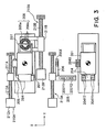
- Figure 3 illustrates a stage system according to a second example
- a flat surface guide is fixedly mounted on a base, not shown.
- a stage 201 for carrying a workpiece thereon is supported by the guide for translational motion along two axes (X and Y) and sliding motion in rotational direction ( ⁇ ).
- linear motor moving elements 204 fixedly mounted which are disposed opposed to a linear motor stator 205 without contact thereto.
- the stator 205 is fixedly connected to a nut 211A through a supporting frame.
- Each linear motor has a structure with a two-pole magnet and one coil as can be extracted out of a conventional linear motor. It produces Lorentz force in accordance with the interactive function of coil electric current and magnetic flux of magnet.
- the linear motor has a moving element provided by an integral structure of two-pole magnet and yoke.
- the linear motor stator is provided by three coils of oblong or elliptical shape. When an electric current is applied to the coil, a thrust is produced in a direction normal to the straight portion of the elliptical coil.
- a coil 205X cooperates with a magnet 204X to produce a force in X direction, to thereby apply a force to the stage 201.
- Coils 205Y1 and 205Y2 cooperate with magnets 204Y1 and 204Y2, respectively, to produce forces in Y direction, respectively, to thereby apply a force to the stage 201.
- a force in ⁇ direction can be applied to the stage 201.
- the X coordinate of the gravity center of the stage 201 is designed so that it is put between the lines of action of the forces to be produced by the coils 205Y1 and 205Y2, while the Y coordinate of the stage gravity center is designed so that it is put on the line of action of the force to be produced by the coil X.
- the distance between the coil 205Y1 and the stage gravity center X coordinate is made equal to the distance between the coil 205Y2 and the stage gravity center X coordinate.
- the linear motor stator 205 is fixed to the nut 211A.
- the nut 211A can be moved in Y direction, by means of a feed screw 213A and a motor 212A.
- the relative stroke of the stator 205 and the moving element 204 is short so that a force can not be applied to the moving element through a long stroke.
- the linear motor stator 205 is made movable in Y direction by means of a feed screw system 210A.
- the linear motor stator 205 applies, to the linear motor moving element 204, a translational force in Y direction and a rotational force for the stage 201.
- X direction since only small distance motion that can be covered by the stroke of the linear motor is required, the linear motor stator is not provided with a motion mechanism in X direction.
- the linear motor is provided with a control system having a hardware or software current limiting system, so that flow of large electric current causing large heat generation is prevented. Additionally, as long as the control system operates normally, there is no flow of electric current causing such heat generation, regardless of the provision of the limiting system (this will be described later).
- a magnetic material plate 207 is provided on the other side of the stage 201.
- the electromagnets 208 are held fixed by using a nut 211B.
- the nut 211B can be moved substantially in the same direction as the stage 201, by means of a motor 212B and a feed screw 213B.
- the feed screw system 210B having nut 211B, motor 212B and feed screw 213B, the paired electromagnets 208 can be moved substantially in the same direction as the stage 201.
- the clearance between the electromagnets 208 and the magnetic material plate 207 can be maintained throughout the long stroke in Y direction, such that the stage can be moved through the long stroke in Y direction on the basis of the attraction force between the magnetic material plate 207 and the electromagnets 208.
- the feed screw system 210B for moving the electromagnets 208 is fixed to the unshown base.
- Each electromagnet of the paired electromagnets and the magnetic material plate are held out of contact with each other, with a small clearance.
- Each electromagnet 208 comprises a yoke 208b of arcuate shape and a coil 208a wound around it.
- an attraction force is produced between the yoke 208b and the magnetic material plate 208.
- the flows of electric currents to the coils of the electromagnets can be controlled independently of each other. Therefore, by adjusting the currents to be applied to the coils, attraction forces to be produced between the magnetic material plate and the electromagnets can be adjusted.
- the combined force applied to the magnetic material plate from the paired electromagnets as well as the direction thereof can be adjusted.
- the linear motor means for such three-axis control system may preferably be made to operate to apply forces to the stage at least at two sides of the stage or from two locations.
- forces are applied to the stage from two sides which are orthogonal to each other. If forces in three-axis directions are produced from only one side, either one of the lines of action of X and Y directions of translation will not pass through the stage gravity center. Therefore, a rotational force will be produced in the stage, and it needs correcting rotational force for suppressing the same.
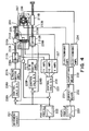
- Figure 4 is a block diagram of a control system for drive controlling the stage system. It comprises movement target specifying means 221 for creating a movement target for the stage 201, position profile producing means 222 for generating the relationship between the time and the stage target position corresponding to that time, on the basis of the created target, and acceleration profile producing means 223 for generating the relationship between the time and the acceleration to be provided during that time, on the basis of the created target.
- the output of the position profile producing means 222 is applied to a fine-motion linear motor position servo system 225 for controlling a fine-motion linear motor 203 and to a movement feedback (FB) system 235A for feedback controlling the motor of the feed screw system 210A, for moving the linear motor stator 205 in Y direction, as well as to a movement feedback (FB) system 235B for feedback controlling the motor of the feed screw system 210B, for moving the electromagnets 208 in Y direction.
- the output of the acceleration profile producing means 223 is applied to an attraction feed-forward (FF) system 231 for feed-forward controlling the attraction force of the electromagnet 208.
- FF attraction feed-forward
- the fine-motion linear motor position servo system 225 comprises calculating means 226, a motor current amplifier 227, a linear motor 203 and an interferometer 228.
- the calculating means 226 operates to perform control calculation, typically such as PID, for example, to a difference between a current target position (X, Y and 9 positions) of the stage as specified by the position profile producing means 222 and the current position (X, Y and 9 positions) of the stage as measured by the interferometer 228.
- the result of calculation is applied, in analog voltage, to the amplifier 227.
- the motor current amplifier 227 is a fine-motion current amplifier for supplying an electric current, proportional to the produced analog output voltage, to each of the linear motors Y1, Y2 and X.
- the linear motor 203 has a structure such as described above, and, in response to the supplied current, it applies a thrust to the stage 201.
- the interferometer 228 serves to measure the position of a reflection mirror 229 mounted on the stage 201, and thus to measure the position (X, Y and ⁇ positions) of the stage (or a moving element provided integrally with the stage).
- Figure 4 while the measurement of the interferometer 228 is depicted by a single measurement line, practically measurements in three axes are performed. Usually, a three-axis interferometer having two beams in Y direction and one beam in X direction may be used.
- the fine-motion linear motor position servo system 225 is an ordinary three-axis position servo system which is operable while using the output of the position profile producing means 222 as a designation signal.
- the attraction feed-forward (FF) system 231 operates to produce the thrust.
- the linear motor 203 is required to produce only small thrust necessary for removing a small positional error with respect to the target position. Therefore, there is no flow of electric current that may cause large heat generation.
- the attraction feed-forward (FF) system 231 produces thrust, no rotational force attributable to it is produced in the stage.
- the flow of electric current is limited by hardware or software, such that, even if the operational association with the attraction feed-forward (FF) system 231 is out of order, flow of electric current causing serious heat generation can be prevented.
- the attraction feed-forward (FF) system 231 is a control system for producing combined thrust between the magnetic material plate 207 and the paired electromagnets 208, which thrust is proportional to the output of the acceleration profile producing means 223.
- the attraction FF system 231 comprises correcting means 232, adjusting means 233 and two electromagnet current amplifiers 234. These amplifiers 234 serve to energize the coils of the electromagnets, independently of each other.
- the correcting means 232 functions to correct non-linear relationship between the electric current and attraction force of the electromagnet, and it includes a square root calculator.
- the attraction force of an electromagnet is proportional to a square of the electric current to the electromagnet.
- the attraction force to be produced to drive the stage is a force which is proportional to the output of the acceleration profile producing means. Therefore, once the square root of the output of the acceleration profile producing means 223 is detected and it is taken as a designating signal, an attraction force proportional to the square of the square root of the output of the acceleration profile producing means can be produced.
- the sign of the output of the acceleration profile producing means 223 may be either positive or negative, the square root calculation may be made to an absolute value of the output and, after the calculation, the sign may be specified when the result is applied to the adjusting means.
- the adjusting means 233 serves to adjust attraction forces functioning between the paired electromagnets 208 and the magnetic material plate 207, so that these forces are combined into a force of desired magnitude and orientation. Regardless of the direction of electric current, the electromagnet can produce only a force for attracting the magnetic material plate. In consideration of it, a pair of electromagnets 208 are placed to sandwich the magnetic material plate 207 therebetween, so that these electromagnets produce and apply opposite forces to the magnetic material plate. By adjusting these two forces, the magnitude and orientation of a combined force acting on the magnetic material plate 207 is controlled.
- One convenient control procedure may be that: in accordance with the sign of the output of the correcting means 232 described above, one of the paired electromagnets to which the electric current is to be applied is selected, and a value proportional to the output of the correcting means 232 is applied to the current amplifier 234 while the electric current to the other electromagnet is kept null. If the output of the correcting means is null, the electric current to both electromagnets is controlled to null. As a result of this, a thrust which is proportional to the output of the acceleration profile producing means 223 is applied from the paired electromagnets 208 to the magnetic material plate 207, in a desired direction.
- Bias electric currents of the same level may be applied to the two electromagnets when the output of the correcting means 232 is null. This provides an effect that the relation between the current and the operation center of BH curve of the electromagnet, that is, the relation between the strength of magnetic field and the magnetic density becomes more linear.
- the correcting means and the adjusting means may function integrally to designate, in response to the output of the acceleration profile, appropriate currents for the two electromagnets.
- the output of the acceleration profile producing means in the positive movement direction is Va
- the bias current is Ib
- the electromagnet coil current for producing an attraction force in the positive movement direction is Ip
- the electromagnet coil current for producing an attraction force in the negative movement direction is Im
- the attraction force of an electromagnet can produce large thrust with a small ampere-turn as compared with the Lorentz force of a linear motor.
- heat generation of electromagnet is very small and it does not cause any inconvenience.
- the movement feedback (FB) system 235A functions to cause the position of the linear motor stator 205 to move and follow the position profile.
- the relative movement range of the stator 205 and the moving element 204 is short and, therefore, a force can not be applied to the moving element for a long distance.
- the linear motor stator 205 is made movable in Y direction by means of the feed screw driving system 210A. As a result, throughout the movable stroke of the stage 201, a translational force in Y direction and a rotational force can be applied to the stage 201 from the linear motor stator 205.
- the position profile is inputted into the position control system which serves to feed back the position of the linear motor stator 205 through an encoder 238A of the motor 212A, such that the stator 205 is moved by means of the motor 212A and the feed screw 213A in accordance with the position profile substantially the same as of the stage 201.
- the relative position of the stator 205 and the stage 201 can be held substantially constant.
- the motor 212 should produce a torque for accelerating the stator 205 and the nut 211A of the feed screw system 210A. Further, it is undesirable that positional errors are accumulated in the position control system at the time of completion of acceleration.
- the output of the acceleration profile producing means may be added to the output of the control calculator and the sum may be inputted into the motor current amplifier. This enables designation of acceleration to the motor, like feed-forward control.
- the screw feed system 210A moves the motor stator 205 substantially at the same speed as the stage.
- the movement feedback (FB) system 235B functions to move the positions of the pair of electromagnets in Y direction in accordance with the position profile. While the electromagnet 208 has an advantage that a large attraction force is produced with small heat generation, the clearance to the magnetic material plate 207 opposed to it should be kept small. In order to assure that a desired force is continuously applied from the electromagnet 208 to the magnetic material plate 207 and then to the stage 201, the electromagnet 208 also should be moved as the stage 201 is moved, so that the clearance is maintained constant.
- position profile is inputted into the position control system which serves to feed back the position of the electromagnet 208 through an encoder 238B of the motor 212B, such that the electromagnet 208 is moved by means of the motor 212B and the feed screw 213B in accordance with the position profile substantially the same as of the stage 201.
- the motor 212B should produce a torque necessary for the acceleration or deceleration of the electromagnet 208 and the nut 211B of the screw system driving system 210B, in addition to a torque corresponding to the combined force of attraction forces produced by the electromagnets during acceleration or deceleration of the stage.
- the output of the acceleration profile producing means may be added to the output of the control calculator and the sum may be inputted into the motor current amplifier. This enables designation of acceleration to the motor, like feed-forward control, and therefore, the electromagnet can be moved without accumulation of positional errors during the stage acceleration. Any way, there is certain amount of heat generation in the motor. However, since the heat source is concentrated locally, it can be cooled relatively easily.
- the screw feed system moves the nut position substantially at the same speed as the stage so that the electromagnet is kept out of contact with the magnetic material plate.
- the stage is accelerated by means of a feed screw system and electromagnets as described above and, when the acceleration is completed, the electric currents to the electromagnets are made null, whereby floor vibration is isolated.
- the positions of the electromagnets are controlled in synchronism with the stage motion so that they are kept out of contact with the magnetic material plate.
- the fine-motion linear motor performs position control constantly at high precision, and large thrust and low heat generation as well as high precision three-axis position control are accomplished at the same time.
- the stator of the linear motor and the moving element provided on the stage are moved in accordance with position profile, and they are controlled substantially at the same position. Therefore, changing coils of the linear motor is not necessary.
- the stage can be driven without creation of thrust non-uniformness, and high precision positioning is assured.
- the line of action of combined force of the thrust produced by the linear motor may be made to pass through the gravity center, and the line of action of the combined force of attraction forces of the electromagnets may be made to pass through the gravity center.
- Figure 5 shows a stage system according to a third example.
- This example corresponds to a modified form of the second example, and it is applied to a three-axis control stage being movable in Y-axis direction through a long stroke and being movable by a small amount in X and ⁇ directions.
- a linear motor 303 have six coils 305a of Y1, Y2, X1, X2, X3 and X4 as illustrated.
- the lines of action of the forces of two coils such as a combination of coils X1 and X2, a combination of coils X3 and X4, or a combination of coils Y1 and Y2, are laid on the same line.
- the center line between the line of action of the force of coil X1 (or of coil X2) and the line of action of the force of the coil X3 (or of coil X4), as well as the line of action of the force of the coil Y1, pass through the gravity center of the stage 301.
- the coils X1 and X2 are driven by one and the same driver.
- the coils X3 and X4 are driven by one and the same driver.
- the coils Y1 and Y2 are driven by one and the same driver.
- a pair of electromagnets are disposed on the opposite sides of a magnetic material plate
- linear motor stator moving feed screw and the electromagnet moving feed screw are provided separately, in this example the linear motor stator and the electromagnet are held by a common supporting frame, for simplification of structure.
- the linear motor means 303 of three-axis control system such as described above may preferably be made to operate to apply forces to the stage 301 at least at two sides of the stage or from two locations.
- forces are applied to the stage from two opposite sides thereof. If forces in three-axis directions are produced from only one side, either one of the lines of action of X and Y directions of translation will not pass through the stage gravity center. Therefore, a rotational force will be produced in the stage, and it needs correcting rotational force for suppressing the same.
- Figure 7 is a block diagram of a control system for drive controlling the stage system. It comprises movement target specifying means 321 for creating a movement target for the stage, position profile producing means 322 for generating the relationship between the time and the stage target position corresponding to that time, on the basis of the created target, and acceleration profile producing means 323 for generating the relationship between the time and the acceleration to be provided during that time, on the basis of the created target.
- movement target specifying means 321 for creating a movement target for the stage
- position profile producing means 322 for generating the relationship between the time and the stage target position corresponding to that time, on the basis of the created target
- acceleration profile producing means 323 for generating the relationship between the time and the acceleration to be provided during that time, on the basis of the created target.
- the output of the position profile producing means 322 is applied to a fine-motion linear motor position servo system 325 for controlling a fine-motion linear motor 303 and to a movement feedback (FB) system 335 for feedback controlling the motor 312 of the feed screw system 310, for moving in Y direction the supporting frame 306 which holds the linear motor stator 305 and the electromagnets 308.
- the output of the acceleration profile producing means 323 is applied to an attraction feed-forward (FF) system 331 for feed-forward controlling the attraction force of the electromagnet 308.
- FF attraction feed-forward
- the fine-motion linear motor position servo system 325 comprises calculating means 326, a motor current amplifier 327, a linear motor 303 and an interferometer 328.
- the calculating means 326 operates to perform control calculation, typically such as PID, for example, to a difference between a current target position (X, Y and ⁇ positions) of the stage as specified by the position profile producing means 322 and the current position (X, Y and ⁇ positions) of the stage 301 as measured by the interferometer 328.
- the result of calculation is applied, in analog voltage, to the amplifier 327.
- the motor current amplifier 327 is a fine-motion current amplifier for supplying an electric current, proportional to the produced analog output voltage, to each of the linear motors Y1 and Y2, linear motors X1 and X2, and linear motors X3 and X4.
- the linear motor means 303 has a structure such as described above, and, in response to the supplied current, it applies a thrust to the stage 301.
- the interferometer 328 serves to measure the position of a reflection mirror 329 mounted on the stage 301, and thus to measure the position (X, Y and ⁇ positions) of the stage (or a moving element provided integrally with the stage).
- the fine-motion linear motor position servo system 325 is an ordinary three-axis position servo system which is operable while using the output of the position profile producing means 322 as a designation signal.
- the attraction feed-forward (FF) system 331 operates to produce the thrust.
- the linear motor 303 is required to produce only small thrust necessary for removing a small positional error with respect to the target position. Therefore, there is no flow of electric current that may cause large heat generation.
- the attraction feed-forward (FF) system 331 produces thrust, no rotational force attributable to it is produced in the stage.
- the flow of electric current is limited by hardware or software, such that, even if the operational association with the attraction feed-forward (FF) system 331 is out of order, flow of electric current causing serious heat generation can be prevented.
- the attraction feed-forward (FF) system 331 is a control system for producing combined thrust between the magnetic material plate 307 and the paired electromagnets 308, which thrust is proportional to the output of the acceleration profile producing means 323.
- the attraction FF system 331 comprises correcting means 332, adjusting means 333 and two electromagnet current amplifiers 334. These amplifiers 334 serve to energize the coils of the electromagnets, independently of each other.
- the correcting means 332 functions to correct non-linear relationship between the electric current and attraction force of the electromagnet, and it includes a square root calculator.
- the attraction force of an electromagnet is proportional to a square of the electric current to the electromagnet.
- the attraction force to be produced to drive the stage is a force which is proportional to the output of the acceleration profile producing means. Therefore, once the square root of the output of the acceleration profile producing means is detected and it is taken as a designating signal, an attraction force proportional to the square of the square root of the output of the acceleration profile producing means can be produced. Namely, an attraction force proportional to the output of the acceleration profile producing means is provided.
- the sign of the output of the acceleration profile producing means 323 may be either positive or negative, the square root calculation may be made to an absolute value of the output and, after the calculation, the sign may be specified when the result is applied to the adjusting means 333.
- the adjusting means 333 serves to adjust attraction forces functioning between the paired electromagnets 308 and the magnetic material plates 307, so that these forces are combined into a force of desired magnitude and orientation. Regardless of the direction of electric current, the electromagnet can produce only a force for attracting the magnetic material plate. In consideration of it, a pair of electromagnets are placed to sandwich the stage therebetween in Y direction, so that these electromagnets produce and apply opposite forces to the magnetic material plates opposed to them, respectively. By adjusting these two forces, the magnitude and orientation of a combined force acting on the magnetic material plates is controlled.
- One convenient control procedure may be that: in accordance with the sign of the output of the correcting means 332 described above, one of the paired electromagnets to which the electric current is to be applied is selected, and a value proportional to the output of the correcting means 332 is applied to the current amplifier 334 while the electric current to the other electromagnet is kept null. If the output of the correcting means is null, the electric current to both electromagnets is controlled to null. As a result of this, a thrust which is proportional to the output of the acceleration profile producing means is applied from the paired electromagnets 308 to the magnetic material plates, in a desired direction.
- Bias electric currents of the same level may be applied to the two electromagnets when the output of the correcting means is null. This provides an effect that the relation between the current and the operation center of BH curve of the electromagnet, that is, the relation between the strength of magnetic field and the magnetic density becomes more linear.
- the correcting means and the adjusting means may function integrally to designate, in response to the output of the acceleration profile, appropriate currents for the two electromagnets.
- the output of the acceleration profile producing means in the positive movement direction is Va
- the bias current is Ib
- the electromagnet coil current for producing an attraction force in the positive movement direction is Ip
- the electromagnet coil current for producing an attraction force in the negative movement direction is Im
- the attraction force of an electromagnet can produce large thrust with a small ampere-turn as compared with the Lorentz force of a linear motor.
- heat generation of electromagnet is very small and it does not cause any inconvenience.
- the movement feedback (FB) system 335 functions to cause the position of the supporting frame 306 to move and follow the position profile.
- the relative movement range of the stator and the moving element is short and, therefore, a force can not be applied to the moving element for a long distance.
- the supporting frame for holding the linear motor stator 305 and the electromagnets 308 is made movable in Y direction by means of the feed screw driving system 310. As a result, throughout the movable stroke of the stage 301, a force can be applied to the stage 301 from the linear motor stator 305 and the electromagnets 308.
- the position profile is inputted into the position control system having a feedback function based on an encoder of the motor, such that the supporting frame is moved by means of the motor and the feed screw in accordance with the position profile substantially the same as of the stage.
- the relative position of the stator 305, the moving element 304, the electromagnet 308 and the magnetic material plate 307 can be held substantially constant.
- the motor 312 should produce a torque for accelerating the supporting frame 306 and the nut 311 of the feed screw system 310. Further, it is undesirable that positional errors are accumulated in the position control system at the time of completion of acceleration.
- the output of the acceleration profile producing means may be added to the output of the control calculator and the sum may be inputted into the motor current amplifier. This enables designation of acceleration to the motor, like feed-forward control, such that stage acceleration can be performed without accumulation of positional errors.
- the screw feed system moves the supporting frame substantially at the same speed as the stage.
- the stage is accelerated by means of a feed screw system and electromagnets, and, when the acceleration is completed, the electric currents to the electromagnets are made null, whereby floor vibration is isolated.
- the positions of the electromagnets are controlled so that they are kept out of contact with the magnetic material plate.
- the fine-motion linear motor performs position control constantly at high precision, and large thrust and low heat generation as well as high precision three-axis position control are accomplished at the same time.
- the stator and electromagnet are held by a common holding frame to be driven by one and the same driving mechanism. This effectively simplifies the structure of the stage system, and reduction in cost and size is attained.
- Linear motors and electromagnets are provided symmetrically with respect to the gravity center of the stage, which accomplishes symmetry of mass distribution of the system. Therefore, no useless rotational force is produced during stage driving.
- a feed screw system may be provided to move the Y-axis driving feed screw system as a whole in X direction, while a flat guide of approximately square shape may be used, to provide long strokes in both of X and Y directions.
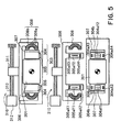
- Figure 8 is a perspective view of a first embodiment of the present invention, wherein a basic structure of the present invention is applied to a wafer stage system.
- a Y yaw guide 550 fixed to a base table 502.
- the side faces of the Y yaw guide 550 and the top face of the base table 502 function to guide a Y stage 551.
- the Y stage 551 is supported by an air slide (not shown) provided on the Y stage 551, slidably along Y direction.
- the Y stage 551 mainly comprises four components of two X yaw guides 552, a large Y slider 553 and a small Y slider 554.
- the large Y slider 553 is disposed opposed to the side faces of the Y yaw guide 550 and the top surface of the base table 502, through air pads (not shown) provided on its side faces and bottom face.
- the small Y slider 554 is disposed opposed to the top face of the base table 502 through air pads (not shown) provided on its bottom face.
- an X stage 561 mainly comprising four components of two X stage side plates 562, an upper X stage top plate 563 and a lower X stage bottom plate 564. These components are disposed to surround the X yaw guide 552 of the Y stage 551, around the X axis.
- the X stage 561 is supported by an air slide (not shown) slidably in X direction, and it is guided by the top face of the base table 502 and the side faces of the two X yaw guides 552 which are components of the Y stage 551.
- the X stage bottom plate 564 is disposed opposed to the top surface of the base table 502, through air pads (not shown) provided on its bottom face.
- the two X stage side plates 562 are disposed opposed to the side faces of the two X yaw guides 552 of the Y stage 551, through air pads (not shown) provided on their side faces.
- the bottom face of the X stage top plate 563 and the top face of the X yaw guide 552, and the top face of the X stage bottom plate 564 and the bottom face of the X yaw guide 552 are held out of contact with each other.
- the X stage 561 as a whole is supported by the side faces of the two X yaw guides 552 and the top face of the base table 502, slidably in X direction as described above.
- the X stage 561 moves in Y direction together with Y-direction motion of the Y stage 551 while on the other hand it is movable in X direction relatively to the Y stage 551.
- it is made slidable two-dimensionally along X and Y directions.
- the driving mechanism for the X-Y stage comprises one long-range linear motor (for X driving) and two long-range linear motors (for Y driving), each being of multiple-phase coil interchanging type.
- the X linear motor 510X for X driving has a stator 512X provided on the Y stage 551 and a moving element 511X provided on the X stage 561. They operate to produce a driving force between the X stage 561 and the Y stage 551.
- the Y linear motors 510Y for Y driving have stators 512Y which may be provided integrally with the base table 502, or they may be provided on a member which is isolated from the base table with respect to vibration.
- the Y linear motors 510Y have moving elements 511Y being made integral with the Y stage 551 through connecting plates 555. With this structure, the Y linear motors 510Y for Y driving function to move the Y stage 551 in Y direction, relatively to the base table 502.
- Each stator 512 of linear motor 510 has plural coils 513 arrayed along the stroke direction and being held by a coil holding frame 514.
- Each moving element 511 of linear motor 510 has four-pole magnets with a magnetic pole pitch corresponding to the coil span of the coils and being arrayed on a yoke plate, and it is provided by box-like magnets formed to be opposed to sandwich the coils. In this long-range linear motor, an electric current is selectively applied to the stator coils in accordance with the position of the moving element, whereby a thrust is produced.
- the wafer top plate 501 (movable stage) has a wafer chuck 571 on which a wafer (workpiece) is to be placed, and it serves to perform wafer positioning with respect to six freedom directions of translational X, Y and Z directions and rotational wx, wy and wz directions.
- the wafer top plate 501 has a rectangular shape, and there is a recess 572 formed at its center.
- the wafer chuck 571 for carrying a wafer thereon is disposed in the recess 572.
- Mounted on side faces of the wafer top plate 501 are mirrors 529 for reflecting laser light of interferometers (first measuring means), for measurement of the position of the wafer top plate 501.
- mirrors 539 or reflecting measurement light of interferometers 538 for performing position measurement to the X stage 561. More specifically, measurement lights from laser interferometers 538 are projected onto the mirrors 539 at the X stage side faces along X and Y directions, such that the position of the X stage 561 with respect to X and Y directions can be measured precisely through the laser interferometers 538.
- mirrors 529 for reflecting laser beams of laser interferometers formed on side faces of the wafer top plate 501, such that the position of the wafer top plate 501 can be measured.
- Six light beams are projected onto the wafer top plate 501, such that the position of the wafer top plate 501 with respect to six freedoms can be measured.
- the position with respect to Y direction as well as the rotational amount in wx and wy directions can be measured.
- the position of the wafer in Z direction i.e., the position of the wafer top plate in Z direction
- the position measurement to the X stage 561 and the position measurement to the wafer top plate 501 can be performed independently of each other, by which their positions can be measured very precisely through laser interferometers.
- Figure 10 is an exploded view of actuator means between the X stage 561 and the wafer top plate 501, which comprises a fine-motion linear motor 503 and an electromagnet 508, for example.
- the X-Y stage Disposed below the wafer top plate 501 is the X-Y stage described above, which provides a reference for application of thrust or attraction force to the wafer top plate 501.
- Each moving element 504 has two sets of dual-pole magnets 574, being magnetized in its thickness direction, and yokes 575. These two sets of magnets 574 and yokes 575 are mutually connected by means of side plates 576, whereby a box-like structure is provided such that linear motor stators 505 (to be described later) are surrounded by them without contact thereto.
- moving elements 505Z of the eight moving elements 504 are disposed approximately at the center of the sides of the rectangular top plate 501, and they provide a Z moving element for minutely (fine-motion) moving the wafer top plate 501 in Z direction, relatively to the X stage 561.
- the dual-pole magnet 574Z is disposed along Z direction, such that, through interaction with the electric current flowing through an elongated ring-like coil 578Z of the Z stator 505Z having a straight portion normal to Z direction, a thrust in Z direction is produced.
- they are called moving elements Z1 - Z4.
- Two moving elements of the remaining four moving elements 504X which are placed at diagonal corners of the rectangular top plate, provide an X moving element for minutely (fine-motion) moving the wafer top plate 501 in X direction, relatively to the X stage 561.
- the dual-pole magnet 574 is disposed along X direction, such that, through interaction with the electric current flowing through an elongated ring-like coil 578X of the X stator 505X having a straight portion normal to X direction, a thrust in X direction is produced.
- they are called moving elements X1 and X2.
- the remaining two moving elements 504Y are also disposed at the diagonal corners of the rectangular top plate 501, and they provide Y moving element for minutely (fine motion) moving the wafer top plate 501 in Y direction, relatively to the X stage 561.
- the dual-pole magnet 574 is disposed along the Y direction, such that, through interaction with the electric current flowing through the elongated ring-like coil 578Y of the Y stator 505Y having a straight portion perpendicular to Y direction, a thrust in Y direction is produced.
- these moving elements are called moving elements Y1 and Y2.
- a magnetic material supporting cylinder 580 of cylindrical shape there is a magnetic material supporting cylinder 580 of cylindrical shape.
- Two (507X) of these magnetic material blocks 507 are disposed along X direction, and they are opposed to electromagnets 508X of E-shape also disposed along X direction, without contact thereto.
- these blocks can receive a large attraction force in X direction from the E-shaped electromagnets 508X.
- the magnetic material blocks 507X of arcuate shape, being disposed along X direction are called blocks X1 and X2.
- the remaining two magnetic blocks 507Y of arcuate shape are disposed along Y direction, and they are opposed to electromagnets 508Y of E-shape also disposed along Y direction, without contact thereto. Thus, these blocks can receive a large attraction force from the electromagnets 508Y.
- the magnetic blocks 507Y disposed along Y direction are called blocks Y1 and Y2.
- a weight compensating spring 581 Disposed inside the central hollow portion of the supporting cylindrical member 580 of magnetic material is a weight compensating spring 581 which has its top end connected to the center of the bottom face of the wafer top plate 501, to support the weight of the wafer top plate 501.
- the weight compensation spring 581 is designed to provide very small spring constants with respect to the weigh supporting direction and other five freedom directions. Thus, transmission of vibration from the X stage 561 to the wafer top plate 501 through the spring 581 can be disregarded.
- the Z coordinates of the lines of action of the forces to be produced by the moving elements X1 and X2 (504X) are approximately registered with each other, and also they are approximately registered with the Z coordinate of the gravity center of the wafer top plate 501, including the four magnetic material blocks 507, magnetic material cylinder 580, moving elements Z1, Z2, Z3 and Z4 (504Z), moving elements Y1 and Y2 (504Y) and moving elements X1 and X2 (504X).
- substantially no rotational force about Y axis acts on the wafer top plate 501.
- the Z coordinates of the lines of action of the forces to be produced by the moving elements Y1 and Y2 (504Y) are approximately registered with each other, and also they are approximately registered with the Z coordinate of the gravity center of the wafer top plate 501, including the four magnetic material blocks 507, magnetic material cylinder 580, moving elements Z1, Z2, Z3 and Z4 (504Z), moving elements Y1 and Y2 (504Y) and moving elements X1 and X2 (504X).
- substantially no rotational force about X axis acts on the wafer top plate 501.
- the Z coordinates of the lines of action of the attraction forces to be applied to the magnetic blocks X1 and X2 (507X) are approximately registered with each other, and also they are approximately registered with the Z coordinate of the gravity center of the wafer top plate 501, including the four magnetic material blocks 507, magnetic material cylinder 580, moving elements Z1, Z2, Z3 and Z4 (504Z), moving elements Y1 and Y2 (504Y) and moving elements X1 and X2 (504X).
- substantially no rotational force about Y axis acts on the wafer top plate 501.
- the X coordinates of the lines of action of the attraction forces to be applied to the magnetic blocks X1 and X2 are approximately registered with the X coordinate of the gravity center of the wafer top plate 501, including the four magnetic material blocks 507, magnetic material cylinder 580, moving elements Z1, Z2, Z3 and Z4 (504Z), moving elements Y1 and Y2 (504Y) and moving elements X1 and X2 (504X).
- substantially no rotational force about Z axis acts on the wafer top plate 501.
- the Z coordinates of the lines of action of the attraction forces to be applied to the magnetic blocks Y1 and Y2 (507Y) are approximately registered with each other, and also they are approximately registered with the Z coordinate of the gravity center of the wafer top plate 501, including the four magnetic material blocks 507, magnetic material cylinder 580, moving elements Z1, Z2, Z3 and Z4 (504Z), moving elements Y1 and Y2 (504Y) and moving elements X1 and X2 (504X).
- substantially no rotational force about X axis acts on the wafer top plate 501.
- the X coordinates of the lines of action of the attraction force in Y direction applied to the magnetic blocks Y1 and Y1 (507Y) are approximately registered with the X coordinate of the gravity center of the wafer top plate 501, including the four magnetic material blocks 507, magnetic material cylinder 580, moving elements Z1, Z2, Z3 and Z4 (504Z), moving elements Y1 and Y2 (504Y) and moving elements X1 and X2 (504X).
- substantially no rotational force about Z axis acts on the wafer top plate 501.
- stators 505 of eight fine-motion linear motors 503 for performing position control of the wafer top plate 501 with respect to six axial directions, as well as four E-shaped electromagnets 508 being supported by an electromagnet supporting cylinder 505, for applying acceleration in X and Y directions to the wafer top plate 501.
- An end of the weight supporting spring for supporting the weight of the wafer top plate 501 is connected to there.
- Each stator 505 has a structure that an elongated ring-like coil 578 is supported by a coil holding frame. It is disposed opposed to the linear motor moving element 504, fixed to the bottom face of the wafer top plate 501, without contact thereto.
- stators 505Z of the eight stators 505 are disposed approximately at the center of the sides of the rectangular X stage top plate 563, and they provide a Z stator for minutely (fine-motion) moving the wafer top plate 501 in Z direction, relatively to the X stage 561.
- this Z stator 505Z a straight portion of the elongated ring-like coil 578Z is disposed to be perpendicular to Z direction, such that a thrust in Z direction can be applied to the dual-pole magnet 574Z of the Z moving element 504Z disposed along Z direction.
- these coils are called coils Z1 - Z4.
- Two stators 505X of the remaining four stators are placed at diagonal corners of the rectangular top plate 563, and they provide an X stator.
- this X stator 505X two straight portions of the elongated ring-like coil 578X are perpendicular to X direction, and two straight portions extend along X direction.
- a thrust in X direction can be applied to the dual-pole magnet 574X of the X moving element 504X, disposed along X direction.
- these coils are called coils X1 and X2.
- the remaining two moving elements 505Y are also disposed at the diagonal corners of the rectangular top plate 563, and they provide Y stator.
- this Y stator 505Y two straight portions of the elongated ring-like coil 578X are perpendicular to Y direction, and two straight portions extend along Y direction.
- a thrust in Y direction can be applied to the dual-pole magnet 574Y of the Y moving element 504Y, disposed along Y direction.
- these coils are called coils Y1 and Y2.
- an electromagnet supporting cylinder 583 Disposed inside the supporting cylinder 583 are four E-shaped electromagnets 508. These electromagnets 508 have magnetic material blocks 585 of approximately E-shaped section as viewed in Z direction, and coils 586. The coil 586 is wound around a central protrusion of the E-like shape. The end faces of the three protrusions of the E-like shape are formed into arcuate shape, not straight.
- Two of the four electromagnets 508 are disposed along X direction and they are opposed to the blocks X1 and X2 (507X), such that attraction forces in X direction and -X direction are applied to the blocks X1 and X2 (507X), respectively.
- they are called electromagnets X1 and X2.
- the remaining two electromagnets 508 are disposed to be opposed to the blocks Y1 and Y2 (507Y), such that attraction forces in Y direction and -Y direction are applied to these blocks Y1 and Y2, respectively.
- they are called electromagnets Y1 and Y2.
- electromagnet 508 can produce attraction force only, in regard to each of the driving directions of X and Y, electromagnets for producing attraction forces in positive and negative directions, respectively, are provided.
- the opposed faces of the magnetic material blocks 507 and the E-shaped electromagnets are defined by portions of a cylindrical face, so that the four magnetic material blocks and the four electromagnets can rotate freely about Z axis (in wx direction), without contact to each other.
- the wafer top plate 501 and the X stage 561 are made relatively movable in wx direction. Further, with rotation in wx direction, there occurs no change in clearance between the end face of the electromagnet 508 and the block 507. Thus, for the same electric current, the attraction force to be produced by the electromagnet 508 does not change.
- the shape of the opposed faces is not limited to this.
- a spherical shape or cup-like shape may be used. Even if the opposed faces of the magnetic blocks and electromagnets are defined along a spherical shape or cup-like shape, it allows relative rotation with respect to three rotational directions of wx, wy and wz. Relative rotation does not cause a change in clearance of opposed faces, and the attraction force of the electromagnet does not change.
- Each of the arcuate magnetic blocks 507 and the E-shaped magnetic blocks 585 is provided by laminating thin plates which are electrically isolated from each other. This effectively prevents flow of eddy current inside the block, due to a change in magnetic flux. Thus, the attraction force of the E-shaped electromagnet 508 can be controlled, up to high frequency.
- thrust can be applied by the linear motor in six axial directions, from the X stage 561 to the wafer top plate 501, and a large attraction force can be applied in X and Y directions by means of the electromagnet 508.
- the thrust or attraction force has to be applied through a long stroke in regard to X and Y directions. Since however both the linear motor 503 and the electromagnet 508 have a very short stroke in X and Y directions whereas the X stage 561 has a long stroke in X and Y directions, the thrust or attraction force is applied to the wafer top plate 501 while moving the X stage 561 in X and Y directions. This assures that the thrust or attraction force in X and Y directions is applied to the wafer top plate 501, throughout the length in X and Y directions.
- Figure 11 is an example of control diagram for performing long-distance motion only in Y direction while a current position is held with regard to the other five directions.
- Movement target designating means 521 produces and applies a target value of the wafer top plate 501, such as positions in respect to six directions, to position profile producing means 522 and acceleration profile producing means 523.
- the position profile producing means 522 creates the relationship between the time and the position of the wafer top plate 501 to be assumed, in respect to each of the six directions of translational X, Y and Z directions and rotational wx, wy and wz directions, on the basis of the target value outputted from the target designating means 521.
- the acceleration profile producing means 523 generates the relationship between the time and the acceleration to be produced, in respect to two axes of translational X and Y directions, on the basis of the target value outputted from the target designating means 521.
- the relationship between the time and the position to be assumed by the gravity center of the wafer top plate 501 as well as the rotation about the gravity center is provided by the position profile producing means 522, while the acceleration profile for the gravity center of the wafer top plate 501 in respect to X and Y directions is provided by the acceleration profile producing means.
- a position profile for movement to the target position is produced only in relation to the Y axis.
- a position profile of constant value for holding the current position is provided.
- acceleration profile similarly, acceleration and deceleration profile in regard to the Y axis is produced by the acceleration profile producing means.
- X axis along which motion is not produced there is no profile.
- the output of the position profile producing means 522 is applied to a fine-motion linear motor (LM) position servo system for controlling the fine-motion linear motor 503. More specifically, the output of gravity center X position profile producing means 522X and the output of Y position profile producing means 522Y are applied also to a long-range linear motor (LM) position servo system 535 for feedback controlling the electric current to the long-distance linear motor 510 of the X-Y stage, for moving the X stage 561 in X and Y directions.
- LM fine-motion linear motor
- X acceleration profile producing means 523X and the output of Y acceleration profile producing means 523Y are applied to an attraction feed-forward (FF) system 531, for feed-forward controlling the attraction force of the electromagnet 508.
- FF attraction feed-forward
- the fine-motion linear motor (LM) position servo system 525 comprises differentiating means 541, calculating means 526, output coordinate converting means 542, a fine-motion current amplifier 527, wafer top plate position measuring system 528, and an input coordinate converting means 543.
- the differentiating means 541 serves to produce a difference between the current target position (X, Y, Z, wx, wy, wz positions) to be currently assumed by the wafer top plate 501, as specified by the position profile producing means 522, and the current position or measured position (X, Y, Z, wx, wy and wz positions) as practically assumed by the wafer top plate 501.
- the calculating means 526 performs control calculation as represented by PID, for example, to calculate driving amounts in six axes.
- the output coordinate converting means 542 performs calculation for distributing driving amounts in six axes to linear motors 503 (X1, X2, Y1, Y2, Z1, Z2, Z3 and Z4), and the results of calculation are produced in analog voltages.
- the fine-motion current amplifier 527 supplies electric currents, proportional to the analog voltages, to the linear motors 503 (X1, X2, Y1, Y2, Z1, Z2, Z3 and Z4).
- the wafer top plate position measuring system includes the aforementioned measuring means with interferometers, for example, for measuring the position (X, Y, Z, wx, wy, wz) approximately at the exposure point of the wafer top plate 501.
- the input coordinate converting means 543 converts the position (X, Y, Z, wx, wy, wz) approximately at the exposure point of the wafer top plate 501 into the position (X, Y, Z, wx, wy, wz) of the gravity center of the wafer top plate 501.
- the fine-motion linear motor (LM) servo system 525 when viewed in regard to each axis, is an ordinary position servo system which takes the output of the position profile producing means 522 as a designated value.
- the attraction feed-forward (FF) system 531 When a large thrust is necessary, the attraction feed-forward (FF) system 531 to be described later produces the force.
- the attraction force of the electromagnet 508 is so arranged that the line of action thereof is registered with the gravity center of the wafer top plate 501, such that any rotational force is not produced in the wafer top plate 501. Therefore, what is required for the fine-motion linear motor 503 is to produce a small thrust for removing a small positional error with respect to the target position.
- the flow of electric current of linear motor may be restricted by hardware or software, such that, even if cooperation with the attraction feed-forward (FF) system 531 is out of order, flow of electric current causing heat generation is prevented.
- the attraction feed-forward (FF) system 531 includes a control system for producing combined thrust in X direction, between the pair of electromagnets X1 and X2 (508X) and blocks X1 and X2 (507X), which thrust is proportional to the output of the acceleration profile producing means 523, as well as a control system for producing combined thrust in Y direction, between the pair of electromagnets Y1 and Y2 (508Y) and blocks Y1 and Y2 (507Y), which thrust is proportional to the output of the acceleration profile producing means 523.
- Each control system comprises correcting means 532, adjusting means 533 and two electromagnet current amplifiers 534 for energizing the coils 586 of the pair of electromagnets 508, independently of each other.
- the correcting means 532 functions to correct non-linear relationship between the electric current and thrust of the electromagnet 508. In many cases, it comprises a square root calculator with a sign preserving function. Generally, the attraction force of an electromagnet is proportional to a square of the electric current to the electromagnet. Since the required attraction force is a force proportional to the output of the acceleration profile producing means 523, once the square root of the output is detected and is taken as a designating signal, an attraction force proportional to the square of the square root of the output of the acceleration profile producing means 523 can be produced. Namely, an attraction force proportional to the output of the acceleration profile producing means 523 is provided. Also, while the output of the acceleration profile producing means 523 bears the sign, the square root calculation may be made to an absolute value of the output and, after the calculation, the sign may be specified when the result is applied to the adjusting means.
- the adjusting means 533 serves to adjust attraction forces functioning between the paired electromagnets 508 and the magnetic material 507, so that these forces are combined into a force of desired magnitude and orientation. Regardless of the direction of electric current, the electromagnet can produce only a force for attracting the magnetic material plate. In consideration of it, a pair of electromagnets 508 are placed to sandwich the magnetic material 507 therebetween, so that these electromagnets produce and apply opposite forces to the magnetic material. By adjusting these two forces, the magnitude and orientation of a combined force acting on the magnetic material 507 is controlled.
- One convenient control procedure may be that: in accordance with the sign of the output of the correcting means 532 described above, one of the paired electromagnets 508 to which the electric current is to be applied is selected, and a value proportional to the output of the correcting means 532 is applied to the current amplifier 534 while the electric current to the other electromagnet 508 is kept null. If the output of the correcting means 532 is null, the electric current to both electromagnets is controlled to null. As a result of this, a thrust which is proportional to the output of the acceleration profile producing means 523 is applied from the paired electromagnets 508 to the magnetic material 507, in a desired direction.
- Bias electric currents of the same level may be applied to the two electromagnets 508 when the output of the correcting means 532 is null.
- This provides an effect that the relation between the current and the operation center of BH curve of the electromagnet, that is, the relation between the strength of magnetic field and the magnetic density becomes more linear.
- the correcting means 532 and the adjusting means 533 may function integrally to designate, in response to the acceleration profile output, appropriate currents for the two electromagnets.
- the output of the acceleration profile producing means in the positive movement direction is Va
- the bias current is Ib
- the electromagnet coil current for producing an attraction force in the positive movement direction is Ip
- the electromagnet coil current for producing an attraction force in the negative movement direction is Im
- the attraction force of an electromagnet can produce large thrust with a small ampere-turn as compared with the Lorentz force of a linear motor.
- heat generation of electromagnet is very small and it does not cause any inconvenience.
- the electric currents to the electromagnets 508 are controlled to null.
- any external disturbance such as floor vibration is not transmitted to the wafer top plate 501 through the electromagnets 508.
- the fine-motion linear motor controls the positioning of the wafer top plate in six axes at high precision.
- a thrust or attraction force in X and Y directions is applied to the wafer top plate 501 while moving, in X and Y directions, the X stage 561 for providing a reference for application of force to the wafer top plate.
- This accomplishes application of a thrust or attraction force in X and Y directions to the top plate 501, through a long distance along X and Y directions.
- the long-range linear motor (LM) position servo system as well as two Y linear motors and one X linear motor, connected to the LM position servo system, are used.
- the long-range linear motor (LM) position servo system 535 has an X control system and a Y control system.
- the X control system controls the X position of the X stage 561 by using one X linear motor, in accordance with the X position profile.
- the Y control system controls the Y positions of the Y stage 551 and X stage 561 by using two Y linear motors, in accordance with the Y position profile.
- the X and Y control systems of the position servo system 535 serve to produce a difference between the X or Y position profile and the current position of the X stage 561 in X or Y direction as measured on the basis of an interferometer beam, projected to the reflection mirror mounted on the side face of the X stage top plate 563. Also, they operate to perform control calculation as represented by PID, for example, to this differential signal, so as to calculate acceleration value in X or Y direction. The result is applied to the X linear motor 510X or Y linear motor 510Y through the X or Y linear motor current amplifier 537.
- the Y linear motor 510Y produces a thrust for accelerating, in Y direction, the whole mass including Y stage 551, X stage 561 and wafer top plate 501, for example
- the X linear motor 510X produces a thrust for accelerating, in X direction, the whole mass including X stage 561 and the wafer top plate 501, for example.
- the output of the acceleration profile producing means 523 is added to the output of the control calculator of the long-range linear motor (LM) position servo system, and the sum is applied to the motor current amplifier.
- the acceleration signal is applied to the linear motor 510 like feed-forward control, thereby to prevent accumulation of positional error during acceleration.
- the acceleration profile is applied in feed-forward control to the attraction feed-forward (FF) system 531 and the long-range linear motor (LM) position servo system 535.
- the profile may be applied to the fine-motion linear motor (LM) position servo system 525 in feed-forward control.
- the acceleration profile may be produced with respect to all the six axes, not only the X and Y directions, and they may be applied to the fine-motion linear motor position servo system 525 in feed-forward control.
- the X stage 561 and the Y stage 551 move in accordance with the X position and Y position profiles.
- the two Y linear motors and the one X linear motor function only to produce a reaction force of thrust as produced by the fine-motion linear motor (X1, X2, Y1 and Y2).
- the wafer top plate 501 is accelerated through the X stage 561 and Y stage 551 being moved by linear motors and through the attraction force of the electromagnet 508, taking the X stage 561 as a reference.
- the electric current to the electromagnet is made null to isolate floor vibration.
- the long-range linear motor position servo system operates to move the X stage 561 and the Y stage 551 in accordance with the X and Y position profiles, in the manner that the electromagnets 508 and the stators or moving elements of the fine-motion linear motor do not contact with each other.
- high precision position control is performed by using the fine-motion linear motor. By doing so, large thrust and low heat generation as well as high precision six-axis position control to the wafer top plate 501 are accomplished simultaneously.
- the position of the X stage 561 which provides a reference for thrust production by the electromagnets 508 or fine-motion linear motors, is measured completely independently of the position of the wafer top plate 501, and the position control is performed by using a completely independent control system.
- Such independent measurement and independent control for the position of the X stage 561 provides significant advantageous results as compared with the control using a relative sensor, such as follows.
- a relative position sensor for measuring the relative position of the X stage 561 and the wafer top plate 501 it must be fixed to the X stage 561 or to the wafer top plate 501. If the sensor is to be fixed securely so as to prevent vibration at the sensor mount, the size of the sensor mount becomes large, causing a problem of interference with any other component or increase of mass. Also, a preamplifier has to be mounted near it, causing decrease of space and increase of mass. Further, the X stage 561 or the wafer top plate 501 should carry a cable for the sensor therewith, which results in increased external disturbance factor.
- the mass of the top plate 561 can be reduced and, therefore, the response speed as a driving force is applied to the wafer top plate 561 increases. This is effective for high speed positioning of the wafer top plate 501. Further, there is no wiring of sensor cable, which is advantageous for high precision positioning.
- a relative position sensor such as a gap sensor
- the position measurement of the X stage 561 uses an interferometer, and thus only the provision of a mirror on a side face of the X-Y stage 561 is necessary.
- the independent measurement and independent control of this embodiment effectively avoids the necessity of cable wiring and prevents increase of mass resulting from mounting amplifies for the relative position sensor.
- rotational amount of the wafer top plate 501 is not mixed into the X and Y position signals as measured by the interferometers. Thus, complicated calculations for the position signal are not necessary.
- any response delay of the wafer top plate 501 is not mixed into the long-range linear motor position servo system, and there is no development of external disturbance.
- the X stage 561 can be moved to a desired position, by supplying a position signal to the long-range position servo system, without operating the fine-motion linear motor servo system for the wafer top plate.
- this embodiment uses eight fine-motion linear motors for fine-motion control of the wafer top plate in six axes, the number is not limited to it. At least six actuators may be necessary to produce a thrust in six axes. As a matter of course, the placement of the actuators is not limited to that in this embodiment.
- the electromagnet 508 can produce attraction force only, this embodiment uses four electromagnets 508 for acceleration and deceleration in X and Y directions. However, use of at least three electromagnets allows X and Y driving. As regards the electromagnet 508, any form may be used as long as it can produce an attraction force to a magnetic member in response to application of electric current. The shape is not limited to the E-shaped form as in this embodiment.
- the position measurement to the X stage 561 uses interferometers and mirrors at side faces of the X stage 561.
- a linear encoder may be provided to the X or Y linear motor, to measure the position of the X stage 561.
- a sensor means capable of measuring a long distance may be used, in place of such linear encoder.
- weight compensating spring for supporting the weight of the wafer top plate may be replaced by a floating force by airs, repulsion force of magnet or actuators for producing a force in Z direction.
- the actuator for producing a force in Z direction may use the the fine-motion linear motor such as describes above. However, in consideration of heat generation of the linear motor, a small heat generation actuator may be used separately from the fine-motion linear motor.
- a barrel base 696 is supported by a floor or a base table 691, through dampers 698.
- the barrel base 696 further supports a reticle stage base 694 as well as a projection optical system 697 which is placed between a reticle stage 695 and a wafer stage 693.
- the wafer stage 693 is supported by a stage base which is supported on the floor or the base table, and it performs positioning of a wafer placed thereon.
- the reticle stage 695 is supported by the reticle stage base which is supported by the barrel base 696.
- the reticle stage is movable while carrying thereon a reticle having a circuit pattern. Exposure light with which a wafer placed on the wafer stage 693 can be exposed to the reticle placed on the reticle stage 695, is supplied from an illumination optical system 699.
- the wafer stage 693 is scanned in synchronism with the reticle stage 695.
- the positions of them are continuously detected by means of laser interferometers and the detected positions are fed back to the driving means for the reticle stage 695 and wafer stage 693.
- the scan start positions of these stages can be correctly set in synchronism with each other, and additionally, the scan speed in the constant speed scan region can be controlled precisely.
- the reticle pattern is printed on the wafer, whereby a circuit pattern is transferred to the latter.
- a stage system according to any one of the preceding embodiments is used as the wafer stage or reticle stage, driving the stage with a large thrust still reduces the heat generation. Also, high speed and high precision exposure can be accomplished.
- Figure 13 is a flow chart of procedure for manufacture of microdevices such as semiconductor chips (e.g. ICs or LSIs), liquid crystal panels, or CCDs, for example.
- semiconductor chips e.g. ICs or LSIs
- liquid crystal panels e.g. LCDs
- CCDs complementary metal-oxide-semiconductors
- Step 1 is a design process for designing a circuit of a semiconductor device.
- Step 2 is a process for making a mask on the basis of the circuit pattern design.
- Step 3 is a process for preparing a wafer by using a material such as silicon.
- Step 4 is a wafer process which is called a pre-process wherein, by using the so prepared mask and wafer, circuits are practically formed on the wafer through lithography.
- Step 5 subsequent to this is an assembling step which is called a post-process wherein the wafer having been processed by step 4 is formed into semiconductor chips. This step includes assembling (dicing and bonding) process and packaging (chip sealing) process.
- Step 6 is an inspection step wherein operation check, durability check and so on for the semiconductor devices provided by step 5, are carried out. With these processes, semiconductor devices are completed and they are shipped (step 7).
- Figure 14 is a flow chart showing details of the wafer process.
- Step 11 is an oxidation process for oxidizing the surface of a wafer.
- Step 12 is a CVD process for forming an insulating film on the wafer surface.
- Step 13 is an electrode forming process for forming electrodes upon the wafer by vapor deposition.
- Step 14 is an ion implanting process for implanting ions to the wafer.
- Step 15 is a resist process for applying a resist (photosensitive material) to the wafer.
- Step 16 is an exposure process for printing, by exposure, the circuit pattern of the mask on the wafer through the exposure apparatus described above.
- Step 17 is a developing process for developing the exposed wafer.
- Step 18 is an etching process for removing portions other than the developed resist image.
- Step 19 is a resist separation process for separating the resist material remaining on the wafer after being subjected to the etching process. By repeating these processes, circuit patterns are superposedly formed on the wafer.
Claims (30)
- Système de platine, caractérisé par :une platine (501), pouvant se déplacer dans une direction prédéterminée ;une première unité (503), configurée pour appliquer une force à la platine (501) dans la direction prédéterminée sans entrer en contact avec elle ;un moyen de déplacement (510), destiné à déplacer l'une de la première unité (503) et d'une structure (561) comprenant la première unité (503) ;un premier moyen de mesure (528), destiné à mesurer au moins l'une de la position et de l'amplitude du mouvement de la platine (501) ; etun second moyen de mesure (538), destiné à mesurer au moins l'une de la position et de l'amplitude du mouvement de l'une de la première unité (503) et de la structure (561) ;caractérisé en ce que :la première unité (503) est commandée en fonction d'une valeur mesurée par ledit premier moyen de mesure (528) et d'informations intéressant une position de consigne de la platine (501) ; etledit moyen de déplacement (510) est commandé en fonction d'une valeur mesurée par ledit second moyen de mesure (538) et d'informations intéressant la position de consigne.
- Système de platine selon la revendication 1, dans lequel la première unité (503) comprend un moteur linéaire (503).
- Système de platine selon la revendication 1 ou 2, dans lequel la première unité (503) possède une fonction destinée à appliquer une force à un centre de gravité de la platine (501).
- Système de platine selon l'une quelconque des revendications 1 à 3, dans lequel ledit moyen de déplacement (510) comprend l'un d'un moteur linéaire et d'une vis à billes.
- Système de platine selon l'une quelconque des revendications 1 à 4, dans lequel la platine (501) peut se déplacer dans les directions de trois degrés de liberté.
- Système de platine selon la revendication 5, dans lequel la première unité (503) est en mesure d'appliquer une force à la platine (501) dans les directions de trois degrés de liberté.
- Système de platine selon la revendication 5 ou 6, dans lequel ledit moyen de déplacement (510) est en mesure de déplacer l'une de la première unité (503) et de la structure (561), dans la direction d'un degré de liberté.
- Système de platine selon l'une quelconque des revendications 1 à 4, dans lequel la platine (501) peut se déplacer dans les directions de six degrés de liberté.
- Système de platine selon la revendication 8, dans lequel la première unité (503) est en mesure d'appliquer une force à la platine dans les directions de six degrés de liberté.
- Système de platine selon la revendication 8 ou 9, dans lequel ledit moyen de déplacement (510) est constitué d'une platine à mouvements croisés X-Y.
- Système de platine selon l'une quelconque des revendications 1 à 10, comprenant en outre une seconde unité (507, 508) distincte de la première unité (503).
- Système de platine selon la revendication 11, dans lequel la seconde unité (507, 508) est commandée en fonction d'informations intéressant une position de consigne de la platine (501).
- Système de platine selon la revendication 12, dans lequel la seconde unité (507, 508) est commandée directement en fonction d'informations intéressant une position de consigne de la platine (501).
- Système de platine selon la revendication 12 ou 13, dans lequel les informations intéressent l'accélération de la platine (501).
- Système de platine selon l'une quelconque des revendications 11 à 14, dans lequel la seconde unité (507, 508) assure une fonction consistant à appliquer une force au centre de gravité de la platine (501).
- Système de platine selon l'une quelconque des revendications 11 à 15, comprenant en outre un second moyen de déplacement (581) destiné à déplacer l'une de la seconde unité et d'une seconde structure (580, 583) comprenant la seconde unité (507, 508).
- Système de platine selon l'une quelconque des revendications 11 à 15, dans lequel ledit moyen de déplacement (510) est en mesure de déplacer la première (503) et la seconde unité (507, 508) d'une seule pièce.
- Système de platine selon l'une quelconque des revendications 11 à 17, dans lequel la seconde unité (507, 508) inclut un électro-aimant (508).
- Système de platine selon la revendication 18, dans lequel la seconde unité (507, 508) comprend au moins un ensemble d'électro-aimants (508) afin de produire des forces opposées entre elles et parallèles à ladite direction prédéterminée.
- Système de platine selon l'une quelconque des revendications 11 à 19, dans lequel la seconde unité (507, 508) est en mesure d'appliquer une force à la platine (501) dans la direction d'un degré de liberté.
- Système de platine selon l'une quelconque des revendications 11 à 20, dans lequel la seconde unité (507, 508) est en mesure d'appliquer une force à la platine (501) dans la direction de deux degrés de liberté.
- Appareil d'exposition, comprenant un système de platine selon l'une quelconque des revendications 1 à 21.
- Appareil selon la revendication 22, dans lequel le système de platine comprend une platine pour tranche (693).
- Appareil selon la revendication 23, dans lequel le système de platine comprend une platine à réticule (695).
- Appareil selon l'une quelconque des revendications 22 à 24, comprenant en outre un système optique de projection (497) destiné à projeter un motif de réticule sur une tranche, dans lequel un élément porteur destiné à supporter le système optique de projection (497) et une base (694) destinée à supporter la platine (501, 693, 695) sont isolés l'un de l'autre en raison des vibrations.
- Procédé de fabrication d'un dispositif, comprenant les étapes consistant à :préparer un appareil d'exposition selon l'une quelconque des revendications 22 à 25 ; ettransférer un motif de réticule sur une tranche à l'aide de l'appareil d'exposition.
- Procédé selon la revendication 26, comprenant en outre les étapes consistant à appliquer un matériau photosensible sur la tranche et à développer la tranche après le transfert du motif de réticule sur celle-ci par une exposition.
- Procédé de commande d'une platine, caractérisé par :une première étape de mesure, consistant à mesurer au moins une d'une position et de l'amplitude du mouvement d'une platine (501, 693, 695) qui peut être déplacée dans une direction prédéterminée ;une seconde étape de mesure, consistant à mesurer au moins l'une d'une position et de l'amplitude du mouvement de l'une d'une unité (503) possédant un actionneur et d'une structure (561) incluant l'unité ;une étape d'application, consistant à appliquer une force à la platine (501, 693, 695) sans contact avec celle-ci, à l'aide de l'unité (503) ;une étape de déplacement, consistant à déplacer l'unité (503) dans une direction prédéterminée à l'aide du moyen de déplacement (510) ;une première étape de commande, consistant à commander l'unité (503) en fonction d'une première valeur de mesure produite dans ladite première étape de mesure et d'informations intéressant une position de consigne de la platine (501, 693, 695) ; etune seconde étape de commande, consistant à commander au moins l'une de la position et de l'amplitude du mouvement soit de l'une de l'unité (503) et de la structure (561), en fonction d'une seconde valeur de mesure produite dans ladite seconde étape de mesure et d'informations intéressant la position de consigne.
- Procédé selon la revendication 28, comprenant en outre une seconde étape d'application, consistant à appliquer une force à la platine (501, 693, 695) à l'aide d'une seconde unité (507, 508) distincte de l'unité (503).
- Procédé selon la revendication 29, dans lequel la seconde unité (507, 508) est commandée par alimentation directe en fonction d'une valeur de consigne.
Priority Applications (2)
| Application Number | Priority Date | Filing Date | Title |
|---|---|---|---|
| EP08008648.1A EP1970941B1 (fr) | 1998-07-29 | 1999-07-28 | Système de dispositifs porte-objet à utiliser dans un appareil d'exposition |
| EP08009497.2A EP1965411B1 (fr) | 1998-07-29 | 1999-07-28 | Système de dispositifs porte-objet à utiliser dans un appareil d'exposition |
Applications Claiming Priority (4)
| Application Number | Priority Date | Filing Date | Title |
|---|---|---|---|
| JP21409498 | 1998-07-29 | ||
| JP21409498 | 1998-07-29 | ||
| JP19747099 | 1999-07-12 | ||
| JP19747099A JP3745167B2 (ja) | 1998-07-29 | 1999-07-12 | ステージ装置、露光装置およびデバイス製造方法ならびにステージ駆動方法 |
Related Child Applications (4)
| Application Number | Title | Priority Date | Filing Date |
|---|---|---|---|
| EP08009497.2A Division EP1965411B1 (fr) | 1998-07-29 | 1999-07-28 | Système de dispositifs porte-objet à utiliser dans un appareil d'exposition |
| EP08008648.1A Division EP1970941B1 (fr) | 1998-07-29 | 1999-07-28 | Système de dispositifs porte-objet à utiliser dans un appareil d'exposition |
| EP08008648.1 Division-Into | 2008-05-08 | ||
| EP08009497.2 Division-Into | 2008-05-23 |
Publications (3)
| Publication Number | Publication Date |
|---|---|
| EP0977244A2 EP0977244A2 (fr) | 2000-02-02 |
| EP0977244A3 EP0977244A3 (fr) | 2005-06-15 |
| EP0977244B1 true EP0977244B1 (fr) | 2013-02-27 |
Family
ID=26510381
Family Applications (3)
| Application Number | Title | Priority Date | Filing Date |
|---|---|---|---|
| EP08008648.1A Expired - Lifetime EP1970941B1 (fr) | 1998-07-29 | 1999-07-28 | Système de dispositifs porte-objet à utiliser dans un appareil d'exposition |
| EP99306002A Expired - Lifetime EP0977244B1 (fr) | 1998-07-29 | 1999-07-28 | Système de support et procédé de commande du support pour l'utilisation dans un appareil d'exposition |
| EP08009497.2A Expired - Lifetime EP1965411B1 (fr) | 1998-07-29 | 1999-07-28 | Système de dispositifs porte-objet à utiliser dans un appareil d'exposition |
Family Applications Before (1)
| Application Number | Title | Priority Date | Filing Date |
|---|---|---|---|
| EP08008648.1A Expired - Lifetime EP1970941B1 (fr) | 1998-07-29 | 1999-07-28 | Système de dispositifs porte-objet à utiliser dans un appareil d'exposition |
Family Applications After (1)
| Application Number | Title | Priority Date | Filing Date |
|---|---|---|---|
| EP08009497.2A Expired - Lifetime EP1965411B1 (fr) | 1998-07-29 | 1999-07-28 | Système de dispositifs porte-objet à utiliser dans un appareil d'exposition |
Country Status (4)
| Country | Link |
|---|---|
| US (2) | US6570645B2 (fr) |
| EP (3) | EP1970941B1 (fr) |
| JP (1) | JP3745167B2 (fr) |
| KR (1) | KR100325644B1 (fr) |
Families Citing this family (62)
| Publication number | Priority date | Publication date | Assignee | Title |
|---|---|---|---|---|
| US6906334B2 (en) * | 2000-12-19 | 2005-06-14 | Nikon Corporation | Curved I-core |
| US20020137358A1 (en) * | 2001-02-08 | 2002-09-26 | Mike Binnard | Multiple point support assembly for a stage |
| JP4612777B2 (ja) * | 2001-03-09 | 2011-01-12 | キヤノン株式会社 | 移動案内装置、それを用いた露光装置及び半導体デバイス製造方法 |
| US6989887B2 (en) * | 2001-06-06 | 2006-01-24 | Nikon Corporation | Dual force mode fine stage apparatus |
| US20030031538A1 (en) * | 2001-06-30 | 2003-02-13 | Applied Materials, Inc. | Datum plate for use in installations of substrate handling systems |
| JP2003022960A (ja) | 2001-07-09 | 2003-01-24 | Canon Inc | ステージ装置及びその駆動方法 |
| US6842226B2 (en) * | 2001-09-21 | 2005-01-11 | Nikon Corporation | Flexure supported wafer table |
| US6888620B2 (en) * | 2001-11-29 | 2005-05-03 | Nikon Corporation | System and method for holding a device with minimal deformation |
| US20030098965A1 (en) * | 2001-11-29 | 2003-05-29 | Mike Binnard | System and method for supporting a device holder with separate components |
| JP3977086B2 (ja) | 2002-01-18 | 2007-09-19 | キヤノン株式会社 | ステージシステム |
| JP3919592B2 (ja) | 2002-04-24 | 2007-05-30 | キヤノン株式会社 | ステージ装置及びその制御方法並びに露光装置 |
| JP4280543B2 (ja) * | 2002-05-08 | 2009-06-17 | キヤノン株式会社 | 移動体機構および露光装置 |
| JP4323759B2 (ja) * | 2002-05-27 | 2009-09-02 | キヤノン株式会社 | 露光装置およびデバイス製造方法 |
| US20040004703A1 (en) * | 2002-07-02 | 2004-01-08 | Hazelton Andrew J. | Method and apparatus for reducing rotary stiffness in a support mechanism |
| JP3849932B2 (ja) * | 2002-08-12 | 2006-11-22 | キヤノン株式会社 | 移動ステージ装置 |
| EP1418017A3 (fr) * | 2002-08-29 | 2008-12-24 | Canon Kabushiki Kaisha | Dispositif de positionnement, appareil d'exposition par faisceau de particules chargé et procédé de fabrication d'un dispositif semiconducteur |
| JP3826087B2 (ja) * | 2002-08-30 | 2006-09-27 | キヤノン株式会社 | 位置決め装置、荷電粒子線露光装置 |
| US6841956B2 (en) * | 2002-09-17 | 2005-01-11 | Nikon Corporation | Actuator to correct for off center-of-gravity line of force |
| JP2004172557A (ja) | 2002-11-22 | 2004-06-17 | Canon Inc | ステージ装置及びその制御方法 |
| JP4153780B2 (ja) * | 2002-11-25 | 2008-09-24 | 富士通株式会社 | システムおよび強誘電体メモリのデータ読み出し方法 |
| JP4227452B2 (ja) * | 2002-12-27 | 2009-02-18 | キヤノン株式会社 | 位置決め装置、及びその位置決め装置を利用した露光装置 |
| US7209219B2 (en) * | 2003-03-06 | 2007-04-24 | Asml Netherlands B.V. | System for controlling a position of a mass |
| JP4261979B2 (ja) | 2003-05-12 | 2009-05-13 | キヤノン株式会社 | 位置決め装置、露光装置およびデバイス製造方法 |
| TWI243291B (en) * | 2003-05-13 | 2005-11-11 | Asml Netherlands Bv | Control system, lithographic apparatus, device manufacturing method, and device manufactured thereby |
| JP4266713B2 (ja) * | 2003-06-03 | 2009-05-20 | キヤノン株式会社 | 位置決め装置及び露光装置 |
| JP2005046941A (ja) | 2003-07-31 | 2005-02-24 | Canon Inc | ケーブル微動ユニット付きステージ装置 |
| JP2005063167A (ja) * | 2003-08-13 | 2005-03-10 | Canon Inc | 位置決め装置及びその制御方法、並びに露光装置 |
| JP2005203567A (ja) * | 2004-01-15 | 2005-07-28 | Canon Inc | 駆動装置、露光装置及びデバイス製造方法 |
| US20050174551A1 (en) * | 2004-02-11 | 2005-08-11 | Nikon Corporation | Position control and heat dissipation for photolithography systems |
| JP4307288B2 (ja) | 2004-02-25 | 2009-08-05 | キヤノン株式会社 | 位置決め装置 |
| JP4298547B2 (ja) | 2004-03-01 | 2009-07-22 | キヤノン株式会社 | 位置決め装置およびそれを用いた露光装置 |
| JP2005294468A (ja) * | 2004-03-31 | 2005-10-20 | Canon Inc | 位置決め装置、露光装置及びデバイス製造方法 |
| US7304715B2 (en) | 2004-08-13 | 2007-12-04 | Asml Netherlands B.V. | Lithographic apparatus and device manufacturing method |
| US20060061218A1 (en) * | 2004-09-21 | 2006-03-23 | Nikon Corporation | Dual force wafer table |
| US7327437B2 (en) * | 2004-12-07 | 2008-02-05 | Asml Netherlands B.V. | Lithographic apparatus and device manufacturing method |
| JP4871027B2 (ja) * | 2006-05-29 | 2012-02-08 | 株式会社日立ハイテクノロジーズ | 試料載置用のステージ、xyステージおよび荷電粒子線装置 |
| US7352149B2 (en) * | 2006-08-29 | 2008-04-01 | Asml Netherlands B.V. | Method for controlling the position of a movable object, a positioning system, and a lithographic apparatus |
| US8223470B2 (en) * | 2006-10-10 | 2012-07-17 | Taiwan Semiconductor Manufacturing Company, Ltd. | Apparatus and method to improve uniformity and reduce local effect of process chamber |
| JP2008153546A (ja) * | 2006-12-19 | 2008-07-03 | Canon Inc | 移動体機構 |
| JP5013941B2 (ja) * | 2007-04-19 | 2012-08-29 | キヤノン株式会社 | ステージ装置、露光装置、及びデバイス製造方法 |
| JP5006122B2 (ja) | 2007-06-29 | 2012-08-22 | 株式会社Sokudo | 基板処理装置 |
| JP5128918B2 (ja) | 2007-11-30 | 2013-01-23 | 株式会社Sokudo | 基板処理装置 |
| JP5160204B2 (ja) * | 2007-11-30 | 2013-03-13 | 株式会社Sokudo | 基板処理装置 |
| JP5179170B2 (ja) | 2007-12-28 | 2013-04-10 | 株式会社Sokudo | 基板処理装置 |
| JP5001828B2 (ja) | 2007-12-28 | 2012-08-15 | 株式会社Sokudo | 基板処理装置 |
| NL1036516A1 (nl) * | 2008-03-05 | 2009-09-08 | Asml Netherlands Bv | Lithographic apparatus and method. |
| KR100917499B1 (ko) * | 2008-09-09 | 2009-09-16 | 충주대학교 산학협력단 | 비접촉 평면 스테이지 및 이의 제어방법 |
| NL1036299C2 (nl) * | 2008-12-10 | 2010-06-11 | Janssen Prec Engineering B V | Een systeem om tegels met micrometernauwkeurigheid ten opzichte van elkaar te positioneren en te fixeren. |
| US8659746B2 (en) * | 2009-03-04 | 2014-02-25 | Nikon Corporation | Movable body apparatus, exposure apparatus and device manufacturing method |
| JP5409813B2 (ja) | 2009-12-26 | 2014-02-05 | キヤノン株式会社 | インプリント装置及び物品の製造方法 |
| EP2469339B1 (fr) | 2010-12-21 | 2017-08-30 | ASML Netherlands B.V. | Appareil lithographique et méthode de fabrication d'un dispositif |
| JP5917255B2 (ja) * | 2012-04-16 | 2016-05-11 | キヤノン株式会社 | 案内装置、露光装置および物品の製造方法 |
| JP2015536125A (ja) | 2012-09-19 | 2015-12-17 | エーエスエムエル ネザーランズ ビー.ブイ. | リラクタンスアクチュエータアセンブリの較正方法、リラクタンスアクチュエータ、リラクタンスアクチュエータを備えるリソグラフィ装置 |
| CN103869634B (zh) * | 2012-12-14 | 2015-08-05 | 北大方正集团有限公司 | 一种聚焦限位调节方法 |
| CN103465043A (zh) * | 2013-09-27 | 2013-12-25 | 苏州凯欧机械科技有限公司 | 一种电磁铁辅助驱动的新型精密定位工作台 |
| JP6182488B2 (ja) * | 2014-03-25 | 2017-08-16 | 株式会社日立製作所 | 位置決め制御装置 |
| WO2015147319A1 (fr) * | 2014-03-28 | 2015-10-01 | 株式会社ニコン | Appareil à corps mobile, appareil d'exposition, procédé de production d'écran plat, procédé de production de dispositif, et procédé d'entraînement de corps mobile |
| JP6611450B2 (ja) * | 2015-03-31 | 2019-11-27 | キヤノン株式会社 | インプリント装置、インプリント方法、及び物品の製造方法 |
| WO2018181912A1 (fr) * | 2017-03-31 | 2018-10-04 | 株式会社ニコン | Appareil d'unité mobile, appareil d'exposition, procédé de fabrication d'écran plat, procédé de fabrication de dispositif, et procédé d'entraînement d'unité mobile |
| JP7005344B2 (ja) * | 2017-12-28 | 2022-01-21 | キヤノン株式会社 | 制御方法、制御装置、リソグラフィ装置、および物品の製造方法 |
| JP7016289B2 (ja) | 2018-05-23 | 2022-02-04 | 株式会社日立製作所 | ステージ装置、荷電粒子線装置および真空装置 |
| CN109571052A (zh) * | 2019-01-10 | 2019-04-05 | 陕西科技大学 | 双伺服驱动差动式移动/摆动工作台装置 |
Family Cites Families (36)
| Publication number | Priority date | Publication date | Assignee | Title |
|---|---|---|---|---|
| US3736880A (en) * | 1971-04-19 | 1973-06-05 | Rohr Industries Inc | Feedback control circuit for magnetic suspension and propulsion system |
| US4656381A (en) * | 1984-04-25 | 1987-04-07 | Fumito Komatsu | Magnetic pole structure having aternate poles extending from a point of bases, for a rotary electric machine |
| JPS61280752A (ja) * | 1985-06-05 | 1986-12-11 | Oopack Kk | 無刷子直流回転電機 |
| JPS6249826A (ja) * | 1985-08-29 | 1987-03-04 | 株式会社トプコン | 非接触式眼圧計の気流吹き付け装置 |
| US4742286A (en) * | 1985-10-29 | 1988-05-03 | Micro-Stage, Inc. | Gas bearing X-Y-θ stage assembly |
| JP2631485B2 (ja) | 1988-01-28 | 1997-07-16 | キヤノン株式会社 | 位置決め装置 |
| EP0353980B1 (fr) * | 1988-08-02 | 1995-05-24 | Canon Kabushiki Kaisha | Méthode de montage |
| JP2960423B2 (ja) * | 1988-11-16 | 1999-10-06 | 株式会社日立製作所 | 試料移動装置及び半導体製造装置 |
| EP0393994B1 (fr) * | 1989-04-17 | 1994-06-15 | SHARP Corporation | Appareil d'entraînement linéaire |
| US5184055A (en) * | 1989-10-06 | 1993-02-02 | Canon Kabushiki Kaisha | Device for positioning control |
| JP2860578B2 (ja) | 1990-03-02 | 1999-02-24 | キヤノン株式会社 | 露光装置 |
| JPH03293586A (ja) * | 1990-03-03 | 1991-12-25 | Fuji Electric Co Ltd | 位置決めテーブル装置 |
| JP3182158B2 (ja) | 1991-02-25 | 2001-07-03 | キヤノン株式会社 | 露光装置用のステージ支持装置 |
| US5684856A (en) * | 1991-09-18 | 1997-11-04 | Canon Kabushiki Kaisha | Stage device and pattern transfer system using the same |
| JPH05134753A (ja) * | 1991-11-14 | 1993-06-01 | Hitachi Ltd | 位置決め装置 |
| DE69322983T2 (de) * | 1992-02-21 | 1999-07-15 | Canon Kk | System zum Steuern von Trägerplatten |
| JPH0718A (ja) | 1992-07-06 | 1995-01-06 | Reiichiro Kawashima | 回転式草刈り機の安全カバー |
| JP2902225B2 (ja) * | 1992-09-30 | 1999-06-07 | キヤノン株式会社 | 位置決め装置 |
| US5699145A (en) * | 1993-07-14 | 1997-12-16 | Nikon Corporation | Scanning type exposure apparatus |
| JP3282751B2 (ja) * | 1993-07-14 | 2002-05-20 | 株式会社ニコン | 走査型露光装置、及び該装置を用いる素子製造方法 |
| JPH07183192A (ja) | 1993-12-22 | 1995-07-21 | Canon Inc | 移動ステージ機構およびこれを用いた露光装置 |
| US5537186A (en) * | 1993-08-03 | 1996-07-16 | Canon Kabushiki Kaisha | Movable stage mechanism and exposure apparatus using the same |
| JPH07115053A (ja) * | 1993-10-15 | 1995-05-02 | Canon Inc | 移動ステージ装置 |
| US5850280A (en) * | 1994-06-16 | 1998-12-15 | Nikon Corporation | Stage unit, drive table, and scanning exposure and apparatus using same |
| JP3815750B2 (ja) | 1995-10-09 | 2006-08-30 | キヤノン株式会社 | ステージ装置、ならびに前記ステージ装置を用いた露光装置およびデバイス製造方法 |
| JP3564833B2 (ja) * | 1995-11-10 | 2004-09-15 | 株式会社ニコン | 露光方法 |
| US5780943A (en) * | 1996-04-04 | 1998-07-14 | Nikon Corporation | Exposure apparatus and method |
| US5940789A (en) * | 1996-05-17 | 1999-08-17 | Nikon Corporation | Stage control method and apparatus with varying stage controller parameter |
| KR19980019031A (ko) * | 1996-08-27 | 1998-06-05 | 고노 시게오 | 스테이지 장치(a stage apparatus) |
| JPH10144603A (ja) * | 1996-11-14 | 1998-05-29 | Canon Inc | ステージ装置およびこれを用いた露光装置 |
| US6490025B1 (en) * | 1997-03-17 | 2002-12-03 | Nikon Corporation | Exposure apparatus |
| US5793052A (en) * | 1997-03-18 | 1998-08-11 | Nikon Corporation | Dual stage following method and apparatus |
| US5904789A (en) * | 1997-11-24 | 1999-05-18 | Imaginal Systematics, L.L.C. | Box spring stapler apparatus and method |
| US6008610A (en) * | 1998-03-20 | 1999-12-28 | Nikon Corporation | Position control apparatus for fine stages carried by a coarse stage on a high-precision scanning positioning system |
| US6260282B1 (en) * | 1998-03-27 | 2001-07-17 | Nikon Corporation | Stage control with reduced synchronization error and settling time |
| US6069417A (en) * | 1998-08-27 | 2000-05-30 | Nikon Corporation | Stage having paired E/I core actuator control |
-
1999
- 1999-07-12 JP JP19747099A patent/JP3745167B2/ja not_active Expired - Fee Related
- 1999-07-26 US US09/359,911 patent/US6570645B2/en not_active Expired - Lifetime
- 1999-07-28 EP EP08008648.1A patent/EP1970941B1/fr not_active Expired - Lifetime
- 1999-07-28 EP EP99306002A patent/EP0977244B1/fr not_active Expired - Lifetime
- 1999-07-28 EP EP08009497.2A patent/EP1965411B1/fr not_active Expired - Lifetime
- 1999-07-29 KR KR1019990031187A patent/KR100325644B1/ko not_active IP Right Cessation
-
2003
- 2003-01-13 US US10/340,624 patent/US20030098966A1/en not_active Abandoned
Also Published As
| Publication number | Publication date |
|---|---|
| EP1970941A3 (fr) | 2012-08-29 |
| US20030098966A1 (en) | 2003-05-29 |
| EP1970941A2 (fr) | 2008-09-17 |
| EP0977244A2 (fr) | 2000-02-02 |
| US6570645B2 (en) | 2003-05-27 |
| EP1965411A3 (fr) | 2012-08-08 |
| KR20000012083A (ko) | 2000-02-25 |
| EP1970941B1 (fr) | 2014-09-10 |
| EP1965411A2 (fr) | 2008-09-03 |
| JP3745167B2 (ja) | 2006-02-15 |
| EP1965411B1 (fr) | 2013-10-16 |
| JP2000106344A (ja) | 2000-04-11 |
| KR100325644B1 (ko) | 2002-02-25 |
| US20020145721A1 (en) | 2002-10-10 |
| EP0977244A3 (fr) | 2005-06-15 |
Similar Documents
| Publication | Publication Date | Title |
|---|---|---|
| EP0977244B1 (fr) | Système de support et procédé de commande du support pour l'utilisation dans un appareil d'exposition | |
| US7034920B2 (en) | Balanced positioning system for use in lithographic apparatus | |
| US6396566B2 (en) | Stage system for exposure apparatus and device manufacturing method in which a stage supporting member and a countermass supporting member provide vibration isolation | |
| US6885430B2 (en) | System and method for resetting a reaction mass assembly of a stage assembly | |
| US6252314B1 (en) | Linear motor and stage system, and scanning exposure apparatus using the same | |
| US6859257B2 (en) | Stage system | |
| JP2002313716A (ja) | デュアル分離されたシステムを有するリソグラフィーツールおよびそれを構成する方法 | |
| US6958808B2 (en) | System and method for resetting a reaction mass assembly of a stage assembly | |
| US7586218B2 (en) | Moving apparatus, exposure apparatus, and device manufacturing method | |
| US6486941B1 (en) | Guideless stage | |
| US7738232B2 (en) | Alignment apparatus | |
| JP4012199B2 (ja) | ステージ装置、露光装置およびデバイス製造方法 | |
| US7154242B2 (en) | Moving member mechanism and control method therefor | |
| JP4012198B2 (ja) | ステージ装置、露光装置およびデバイス製造方法 | |
| JP4553405B2 (ja) | 位置決め装置、露光装置およびデバイス製造方法 | |
| JP2001230178A (ja) | 位置決め装置、露光装置およびデバイス製造方法 | |
| US20030097205A1 (en) | Control scheme and system for active vibration isolation | |
| US20030139044A1 (en) | Moving apparatus and control method therefor, and device manufacturing method | |
| US6801300B2 (en) | System and method for switching position signals during servo control of a device table | |
| WO2001081171A1 (fr) | Etage de plaquette a supports magnetiques | |
| JP2001230177A (ja) | 位置決め装置、露光装置およびデバイス製造方法 |
Legal Events
| Date | Code | Title | Description |
|---|---|---|---|
| PUAI | Public reference made under article 153(3) epc to a published international application that has entered the european phase |
Free format text: ORIGINAL CODE: 0009012 |
|
| AK | Designated contracting states |
Kind code of ref document: A2 Designated state(s): AT BE CH CY DE DK ES FI FR GB GR IE IT LI LU MC NL PT SE |
|
| AX | Request for extension of the european patent |
Free format text: AL;LT;LV;MK;RO;SI |
|
| RIC1 | Information provided on ipc code assigned before grant |
Ipc: 7G 03F 7/20 B Ipc: 7H 01L 21/00 A |
|
| PUAL | Search report despatched |
Free format text: ORIGINAL CODE: 0009013 |
|
| AK | Designated contracting states |
Kind code of ref document: A3 Designated state(s): AT BE CH CY DE DK ES FI FR GB GR IE IT LI LU MC NL PT SE |
|
| AX | Request for extension of the european patent |
Extension state: AL LT LV MK RO SI |
|
| 17P | Request for examination filed |
Effective date: 20051215 |
|
| AKX | Designation fees paid |
Designated state(s): DE GB NL |
|
| 17Q | First examination report despatched |
Effective date: 20071022 |
|
| GRAP | Despatch of communication of intention to grant a patent |
Free format text: ORIGINAL CODE: EPIDOSNIGR1 |
|
| RIN1 | Information on inventor provided before grant (corrected) |
Inventor name: EBINUMA, RYUICHI, Inventor name: KORENAGA, NOBUSHIGE, |
|
| GRAS | Grant fee paid |
Free format text: ORIGINAL CODE: EPIDOSNIGR3 |
|
| GRAA | (expected) grant |
Free format text: ORIGINAL CODE: 0009210 |
|
| AK | Designated contracting states |
Kind code of ref document: B1 Designated state(s): DE GB NL |
|
| REG | Reference to a national code |
Ref country code: GB Ref legal event code: FG4D |
|
| REG | Reference to a national code |
Ref country code: DE Ref legal event code: R096 Ref document number: 69944637 Country of ref document: DE Effective date: 20130425 |
|
| REG | Reference to a national code |
Ref country code: NL Ref legal event code: T3 |
|
| PLBE | No opposition filed within time limit |
Free format text: ORIGINAL CODE: 0009261 |
|
| STAA | Information on the status of an ep patent application or granted ep patent |
Free format text: STATUS: NO OPPOSITION FILED WITHIN TIME LIMIT |
|
| 26N | No opposition filed |
Effective date: 20131128 |
|
| REG | Reference to a national code |
Ref country code: DE Ref legal event code: R097 Ref document number: 69944637 Country of ref document: DE Effective date: 20131128 |
|
| GBPC | Gb: european patent ceased through non-payment of renewal fee |
Effective date: 20130728 |
|
| PG25 | Lapsed in a contracting state [announced via postgrant information from national office to epo] |
Ref country code: GB Free format text: LAPSE BECAUSE OF NON-PAYMENT OF DUE FEES Effective date: 20130728 |
|
| PGFP | Annual fee paid to national office [announced via postgrant information from national office to epo] |
Ref country code: NL Payment date: 20160606 Year of fee payment: 18 |
|
| PGFP | Annual fee paid to national office [announced via postgrant information from national office to epo] |
Ref country code: DE Payment date: 20160731 Year of fee payment: 18 |
|
| REG | Reference to a national code |
Ref country code: DE Ref legal event code: R119 Ref document number: 69944637 Country of ref document: DE |
|
| REG | Reference to a national code |
Ref country code: NL Ref legal event code: MM Effective date: 20170801 |
|
| PG25 | Lapsed in a contracting state [announced via postgrant information from national office to epo] |
Ref country code: NL Free format text: LAPSE BECAUSE OF NON-PAYMENT OF DUE FEES Effective date: 20170801 Ref country code: DE Free format text: LAPSE BECAUSE OF NON-PAYMENT OF DUE FEES Effective date: 20180201 |