EP0908928B1 - Brennofen und Kontrollverfahren dafür - Google Patents
Brennofen und Kontrollverfahren dafür Download PDFInfo
- Publication number
- EP0908928B1 EP0908928B1 EP98119051A EP98119051A EP0908928B1 EP 0908928 B1 EP0908928 B1 EP 0908928B1 EP 98119051 A EP98119051 A EP 98119051A EP 98119051 A EP98119051 A EP 98119051A EP 0908928 B1 EP0908928 B1 EP 0908928B1
- Authority
- EP
- European Patent Office
- Prior art keywords
- baking furnace
- inlet
- air
- front chamber
- disposed
- Prior art date
- Legal status (The legal status is an assumption and is not a legal conclusion. Google has not performed a legal analysis and makes no representation as to the accuracy of the status listed.)
- Expired - Lifetime
Links
- 238000000034 method Methods 0.000 title claims description 12
- 238000010438 heat treatment Methods 0.000 claims description 44
- 239000000463 material Substances 0.000 claims description 15
- 238000005259 measurement Methods 0.000 claims description 2
- 238000010276 construction Methods 0.000 description 9
- 238000009826 distribution Methods 0.000 description 8
- 239000000567 combustion gas Substances 0.000 description 6
- 239000003989 dielectric material Substances 0.000 description 4
- 238000007599 discharging Methods 0.000 description 4
- 239000011521 glass Substances 0.000 description 4
- 239000004065 semiconductor Substances 0.000 description 4
- 235000012431 wafers Nutrition 0.000 description 4
- 238000001816 cooling Methods 0.000 description 3
- 230000000694 effects Effects 0.000 description 3
- 230000007246 mechanism Effects 0.000 description 3
- 230000007423 decrease Effects 0.000 description 2
- 238000004519 manufacturing process Methods 0.000 description 2
- QVGXLLKOCUKJST-UHFFFAOYSA-N atomic oxygen Chemical compound [O] QVGXLLKOCUKJST-UHFFFAOYSA-N 0.000 description 1
- 239000000919 ceramic Substances 0.000 description 1
- 238000004320 controlled atmosphere Methods 0.000 description 1
- 230000003247 decreasing effect Effects 0.000 description 1
- 239000007789 gas Substances 0.000 description 1
- 239000002184 metal Substances 0.000 description 1
- 238000012544 monitoring process Methods 0.000 description 1
- 230000001590 oxidative effect Effects 0.000 description 1
- 239000001301 oxygen Substances 0.000 description 1
- 229910052760 oxygen Inorganic materials 0.000 description 1
- 230000001681 protective effect Effects 0.000 description 1
- 238000005476 soldering Methods 0.000 description 1
- 230000001360 synchronised effect Effects 0.000 description 1
- 230000007723 transport mechanism Effects 0.000 description 1
- 238000011144 upstream manufacturing Methods 0.000 description 1
Images


Classifications
-
- F—MECHANICAL ENGINEERING; LIGHTING; HEATING; WEAPONS; BLASTING
- F27—FURNACES; KILNS; OVENS; RETORTS
- F27B—FURNACES, KILNS, OVENS, OR RETORTS IN GENERAL; OPEN SINTERING OR LIKE APPARATUS
- F27B9/00—Furnaces through which the charge is moved mechanically, e.g. of tunnel type; Similar furnaces in which the charge moves by gravity
- F27B9/14—Furnaces through which the charge is moved mechanically, e.g. of tunnel type; Similar furnaces in which the charge moves by gravity characterised by the path of the charge during treatment; characterised by the means by which the charge is moved during treatment
- F27B9/20—Furnaces through which the charge is moved mechanically, e.g. of tunnel type; Similar furnaces in which the charge moves by gravity characterised by the path of the charge during treatment; characterised by the means by which the charge is moved during treatment the charge moving in a substantially straight path tunnel furnace
- F27B9/24—Furnaces through which the charge is moved mechanically, e.g. of tunnel type; Similar furnaces in which the charge moves by gravity characterised by the path of the charge during treatment; characterised by the means by which the charge is moved during treatment the charge moving in a substantially straight path tunnel furnace being carried by a conveyor
- F27B9/2407—Furnaces through which the charge is moved mechanically, e.g. of tunnel type; Similar furnaces in which the charge moves by gravity characterised by the path of the charge during treatment; characterised by the means by which the charge is moved during treatment the charge moving in a substantially straight path tunnel furnace being carried by a conveyor the conveyor being constituted by rollers (roller hearth furnace)
-
- F—MECHANICAL ENGINEERING; LIGHTING; HEATING; WEAPONS; BLASTING
- F27—FURNACES; KILNS; OVENS; RETORTS
- F27B—FURNACES, KILNS, OVENS, OR RETORTS IN GENERAL; OPEN SINTERING OR LIKE APPARATUS
- F27B9/00—Furnaces through which the charge is moved mechanically, e.g. of tunnel type; Similar furnaces in which the charge moves by gravity
- F27B9/30—Details, accessories, or equipment peculiar to furnaces of these types
- F27B9/3005—Details, accessories, or equipment peculiar to furnaces of these types arrangements for circulating gases
-
- F—MECHANICAL ENGINEERING; LIGHTING; HEATING; WEAPONS; BLASTING
- F27—FURNACES; KILNS; OVENS; RETORTS
- F27B—FURNACES, KILNS, OVENS, OR RETORTS IN GENERAL; OPEN SINTERING OR LIKE APPARATUS
- F27B9/00—Furnaces through which the charge is moved mechanically, e.g. of tunnel type; Similar furnaces in which the charge moves by gravity
- F27B9/30—Details, accessories, or equipment peculiar to furnaces of these types
- F27B9/40—Arrangements of controlling or monitoring devices
-
- H—ELECTRICITY
- H01—ELECTRIC ELEMENTS
- H01L—SEMICONDUCTOR DEVICES NOT COVERED BY CLASS H10
- H01L21/00—Processes or apparatus adapted for the manufacture or treatment of semiconductor or solid state devices or of parts thereof
- H01L21/67—Apparatus specially adapted for handling semiconductor or electric solid state devices during manufacture or treatment thereof; Apparatus specially adapted for handling wafers during manufacture or treatment of semiconductor or electric solid state devices or components ; Apparatus not specifically provided for elsewhere
- H01L21/67005—Apparatus not specifically provided for elsewhere
- H01L21/67011—Apparatus for manufacture or treatment
- H01L21/67098—Apparatus for thermal treatment
- H01L21/67109—Apparatus for thermal treatment mainly by convection
Definitions
- the present invention relates to a baking furnace and a control method therefor, which are used for the baking of electrodes for plasma displays or semiconductors and the baking of paste for dielectrics.
- a baking furnace is an indispensable device for a process which involves the baking of electrodes of plasma displays or semiconductors or the baking of paste for dielectrics.
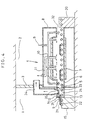
- the construction of a conventional baking furnace will now be described using a sectional view in Fig. 5 .
- a conventional baking furnace 4 comprises transfer rollers 5, a muffle 6 made of heat resistant glass, a heater 7, a cover, an air feed pipe system 10, an exhaust pipe 11, and an inlet conveyor 15, an outlet conveyor 20.
- the muffle 6 is in the form of a flat box rectangular in cross section, extending from the inlet 31 to the outlet 32 of the baking furnace 4.
- the heater 7 is disposed on the outer periphery of the muffle 6.
- the air feed pipe system 10 is connected to the muffle 6 to feed air 9 into the latter.
- the exhaust pipe 11 is a pipe for discharging combustion gases in the muffle 6 to the outside of the baking furnace 4.
- the muffle 6 and heater 7 are covered by a cover 8.
- An inlet conveyor 15 is disposed at the inlet 31 of the baking furnace 4 and an outlet conveyor 20 at the outlet 32. Boards 21 supported on support plates 22 enter the baking furnace 4 from the inlet conveyor 15 and are baked as they are transferred in the muffle 6 by the transfer rollers 5 until they are taken out onto the outlet conveyor 20.
- the inlet 31 of the conventional baking furnace 4 is positioned on the side associated with a clean room 1.
- the outlet 32 of the baking furnace 4 is positioned on the side associated with a normal pressure room 2.
- the clean room 1 and the normal pressure room 2 are separated by a wall 3.
- the clean room 1 is about 5 - 10 Pa higher in pressure than the normal pressure room 2.
- the difference in pressure between the inlet 31 and outlet 32 of the baking furnace 4 causes the air in the clean room 1 to flow in the muffle 6 from the inlet 31 to the outlet 32 of the baking furnace 4.
- the difference in pressure between the clean room 1 and the normal pressure room 2 is 10 Pa
- the flow rate of the air flowing in the muffle 6 is 4 m/sec, and in the case of 5 Pa, it is 3 m/sec. Since the cool air in the clean room 1 flows into the baking furnace 4 at said flow rate, the temperature distribution in the muffle 6 varies, presenting a problem that the baking conditions vary to the extent that a baked product of predetermined baking quality cannot be obtained.
- the present invention is intended to solve said problems and provide a baking furnace and a control method therefor, by which a baked product of predetermined baking quality can be obtained.
- US-A-3,982,887 discloses a furnace for flux-free soldering of workpieces in a controlled atmosphere.
- the furnace comprises a first lock chamber, interposed between an inlet (preheating) chamber and the furnace chamber, and a second lock chamber interposed between the furnace chamber and an outlet (cooling) chamber.
- the lock chambers are adapted to create vacuum inside the chambers, have gates which can be raised and lowered synchronized with transport means to allow workpieces to travel form the input chamber via the furnace chamber to the output chamber.
- the lock chambers and the furnace are heated by heating elements for heating a protective gas admitted into these chambers.
- US-A-5,044,944 discloses s furnace adapted to control an atmosphere of decreased oxygen concentration by being divided into a plurality of zones, by supplying a non-oxidizing atmosphere into each of the zones, and by increasing the internal pressure thereby.
- Each zone comprises heating elements.
- Shutter devices are provided for checking the flowing atmosphere between the zones, allowing for workpieces to be moved during short periods of opening from one zone into the next one by transport means which are provided for this purpose independently from one another in each zone.
- EP-A-0 582 039 discloses an automatic heat treatment system for eliminating thermal donor of semiconductor wafers.
- Heating means, cooling means and transporting means are integrated in a heat treatment system comprising a loading section for supplying the wafers in succession, an outlet section for receiving the wafers after treatment, and a heat treatment section associated with the loading section and the outlet section via a transport mechanism for transferring the wafers.
- Heating means are provided at positions along the transfer mechanism close to the loading section and cooling means provided at positions close to the outlet section, which all can be monitored by a controller for monitoring temperatures.
- a baking furnace comprises a heating chamber having an inlet disposed in a first space and an outlet disposed in a second space whose pressure is lower than that of the first space, said inlet and outlet being for a material to be heated, transfer means disposed in said heating chamber for transferring the material to be heated which has been transferred to said heating chamber, heating means disposed in the vicinity of said heating chamber, air discharge means connected to a place in the vicinity of the inlet of said heating chamber, differential pressure detecting means installed outside said heating chamber for detecting the difference in pressure between said first and second spaces, and discharge control means for controlling the operation of said air discharge means on the basis of information from said differential pressure detecting means.
- the air flowing from the inlet into a space in the vicinity of the inlet of the heating chamber can be discharged to the outside of the baking furnace by using the air discharge means installed in the vicinity of the inlet, thus making it possible to prevent the air from flowing into the innermost region of the heating chamber. Therefore, the temperature distribution in the baking furnace can be maintained constant, whereby a baked product of predetermined baking quality can be obtained.
- the baking furnace comprises a front chamber whose inlet disposed in a first space is provided with opening and closing means, a heating chamber connected to said front chamber through an opening and having an outlet disposed in a second space whose pressure is lower than that of said first space, heating means disposed in the vicinity of said heating chamber, first transfer means installed in said front chamber for transferring a material to be heated by switching the transfer speed between high and low, and second transfer means installed in said heating chamber for transferring said material at low speed.
- the opening and closing means is closed except when the material is transferred to the front chamber and since the material can be transferred at high seed to the front chamber, the time during which the opening and closing means is opened can be shortened.
- the amount of air flowing through the inlet into the front chamber can be minimized and the air can be substantially prevented from flowing into the heating chamber.
- the temperature distribution in the baking furnace can be maintained constant and a baked product of predetermined baking quality can be obtained.
- this baking furnace is simpler in construction, making it possible to reduce the production costs thereof.
- a baking furnace comprises a front chamber having an inlet disposed in a first space, a heating chamber connected to said front chamber through an opening and having an outlet disposed in a second space whose pressure is lower than that of said first space, transfer means disposed in said front chamber and heating chamber for transferring a material to be heated, heating means disposed in the vicinity of the heating chamber, and an air discharge pipe having a suction port at one end thereof connected to the front chamber and an exhaust port at the other end disposed in the second space.
- the cross sectional area of the air discharge pipe can be made greater than that of the opening in the baking furnace inlet, and the air flowed into the front chamber flows only little in the direction of the baking furnace, most of the air being discharged through the air discharge pipe. Further, the construction can be made simpler.
- a baking furnace according to the invention is provided with discharge assisting means for facilitating air flowed into said front chamber through said inlet to flow toward said air discharge pipe.
- the air flowed into the front chamber can be guided in the direction of the air discharge pipe by the discharge assisting means, so that the air can be discharged mostly through the air discharge pipe.
- a control method for controlling a baking furnace described in Claim 1 of the invention comprises the steps of measuring the difference in pressure between said first and second spaces by said differential pressure detecting means, and controlling the amount of air being discharged by said air discharge means by said discharge control means according to the results of the measurement.
- the amount of air being discharged by said air discharge means can be changed according to the differential pressure detected by the differential pressure detecting means, so that the air can be discharged only by an amount equal to the amount of the air which has been flowed in, thus preventing the air from flowing into the heating chamber.
- a control method for controlling a baking furnace described in Claims 2 or 4 of the invention comprises the steps of closing said opening and closing means except when said material to be heated is transferred to said front chamber, and transferring said material at high speed to said front chamber by said first transfer means, thereby restricting the air from flowing into said baking furnace.
- the amount of air flowing into the front chamber is restricted to being very small, so that the air flowed into the front chamber can be prevented from flowing directly into the heating chamber.
- FIG. 1 is a sectional view
- Fig. 2 is a sectional view taken along the line Z-Z in Fig. 1 .
- arrangements which are the same as in the prior example described above are denoted by the same reference characters.
- a baking furnace 4 lies across the boundary between a clean room 1 and a normal pressure room 2.
- the clean room 1 and the normal pressure room 2 are separated by a wall 3.
- the pressure in the clean room 1 is controlled so that it is 5-10 Pa higher than that of the normal pressure room 2.
- the baking furnace 4 comprises a muffle 6 forming a heating chamber, transfer rollers 5 disposed to extend from the inlet to the outlet of the muffle 6, a heater 7 disposed on the outer periphery of the muffle 6 for heating boards 21 to be baked, a cover 8 which covers the muffle 6 and heater 7, an air feed pipe system 10 having a plurality of spouts for feeding air into the muffle 6, an exhaust pipe 11 having suction ports disposed in the upper region of the muffle 6 for discharging combustion gases in the muffle 6, a front chamber 24 composed of a hood 12 and an airtight cover 13, a control plate 14 for controlling the opening of the inlet 31 of the front chamber 24, an inlet conveyor 15 disposed in the inlet of the muffle 6, a differential pressure gauge (differential pressure detecting means) 16 for measuring the difference in pressure between the clean room 1 and the normal pressure room 2, a controller 17 for producing a control signal from the results of the differential pressure gauge 16, a frequency-variable inverter 18, an exhaust fan 19 for discharging
- the transfer rollers 5 are driven by a driving source (not shown).
- the muffle 6 is in the form of a flat box rectangular in cross section, extending from the inlet of the baking furnace 4, i.e., an opening 33 in the latter, to the outlet 32.
- the heater 7 is disposed on the outer periphery of the muffle 6.
- the air feed pipe system 10 is used to feed air 9 into the muffle 6, having spouts for air 9 disposed respectively in the vicinity of the inlet of the baking furnace 4, in the muffle 6, and in the vicinity of the outlet of the barking furnace 4.
- the suction ports of the exhaust pipe 11 are attached in the muffle 6 for discharging combustion gases in the muffle 6 into the outside of the baking furnace 4.
- the hood 12 is installed at the inlet of the baking furnace 4 and has an exhaust port disposed in the upper portion thereof.
- the airtight cover 13 is disposed in a lower surface for the transfer rollers 5 within the hood 12, whereby the air flowed into the front chamber 24 from the clean room 1 is prevented from leaking through the lower surface for the transfer rollers 5.
- the hood 12 and airtight cover 13 are integrally combined to constitute the front chamber 24 of the baking furnace 4.
- the front chamber 24 is formed with the inlet 31 for transfer.
- the control plate 14 is disposed at the inlet 31 of the front chamber 24 and controls the amount of air flowing from the clean room 1 into the front chamber 24.
- the inlet conveyor 15 is disposed at the inlet 31 of the front chamber 24, while the outlet conveyor 20 is disposed at the outlet 32 of the baking furnace 4.
- the differential pressure gauge 16 comprises a first measuring port 16a having an end disposed in the normal pressure room 2, and a second measuring port 16b having an end disposed in the clean room 1.
- the controller 17 changes the frequency of the inverter 18 according to the output from the differential pressure gauge 16 so as to control the rpm of the exhaust fan 19 and control the amount of discharge of air.
- the exhaust from the exhaust fan 19 is disposed in a return duct 23 leading to the clean room 1; thus, it is arranged that the exhaust is returned to the clean room 1.
- the support plates 22 are moved by the transfer rollers 5, traveling through the inlet 31 of the front chamber 24 and the opening 33 in the baking furnace 4 to the outlet 32 of the baking furnace 4.
- the support plates 22 are heat resistant boards whose size is, for example, 850 mm long, 1300 mm wide and 5 mm thick.
- the boards 21 to be baked are, for example, glass plates coated with paste, being 554 mm long, 980 mm wide and 2.8 mm thick.
- the boards 21 supported on the support plates 22 are conveyed into the front chamber 24 by the inlet conveyor 15 and transferred through the front chamber 24 to the baking furnace 4 by the transfer rollers 5.
- the boards 21 are passed through the muffle 6 heated by the heater 7.
- the baking furnace 4 has been controlled to have a predetermined temperature distribution established therein.
- Fresh air 9 is fed into the muffle 6 through the air feed pipe system 10.
- Combustion gases are exhausted into the outside of the baking furnace 4 through the exhaust pipe 11.
- An adjustment has been made so that the feeding of air 9 into the baking furnace 4 and the exhaust of combustion gases are substantially balanced.
- the front chamber 24 is located upstream of the baking furnace 4, the control plate 14 is installed at the inlet of the front chamber 4, and the position of the control plate 14 is controlled to decrease the area of the opening.
- the opening 33 As an example of the opening 33, suppose that the width of the opening is 1500 mm and its height is 20 mm. Then, the area of the opening is 0.03 m 2 . With a differential pressure of 10 Pa, the air speed is 4 m 2 /sec; thus, it follows that 0.12 m 2 /sec of air flows into the baking furnace 4 through the inlet.
- the exhaust fan 19 is driven to discharge substantially the same amount of air into the clean room 1 as the amount of air flowed into the front chamber 24, thereby reducing to zero the air inflow from the clean room 1 into the baking furnace 4.
- the exhaust fan 19 is driven to discharge substantially the same amount of air into the clean room 1 as the amount of air flowed into the front chamber 24, thereby reducing to zero the air inflow from the clean room 1 into the baking furnace 4.
- the baking furnace 4 is operated in such a manner as to ensure that the difference in pressure between the clean room 1 and the normal pressure room 2 is constant at all times, in reality there is a variation of 5 - 10 Pa in pressure difference.
- the pressure difference is detected by the differential pressure gauge 16 and the frequency of the inverter 18 is changed by the controller 17 to change the rpm of the exhaust fan, thereby controlling the rate of discharge of air into the clean room 1.
- the hood 12 and airtight cover 13 are integrally formed to provide the front chamber 24 for the baking furnace 4 and the exhaust port is disposed in the top of the hood 12.
- a baking furnace having no front chamber 24 may be formed wherein said exhaust port is disposed directly in a place in the muffle close to the inlet of the baking furnace 4, and the air discharge means (inverter 18, exhaust fan 19, and return duct 23) and the discharge control means (differential pressure gauge 16 and controller 17) are installed, with the hood 12 and airtight cover 13 removed.
- a baking furnace 4 is installed across the boundary between a clean room 1 and a normal pressure room 2.
- the clean room 1 and the normal pressure room 2 are separated by a wall 3.
- the pressure in the clean room 1 is controlled so that it is 5 - 10 Pa higher than that of the normal pressure room 2.
- the baking furnace 4 comprises transfer rollers 5, a muffle 6, a heater 7, a cover 8, an air feed pipe system 10, an exhaust pipe 11, an inlet cover 25 constituting a front chamber 241, a shutter 26 disposed at the inlet 31 of the front chamber 241, a cylinder 30 for opening and closing the shutter 26, an inlet conveyor 15, a first motor 27, a second motor 28 and a third motor 29 for driving the transfer rollers 5, an outlet conveyor 20, and support plates 22.
- the muffle 6 is in the form of flat box rectangular in cross section, extending from the inlet of the baking furnace 4, i.e., an opening 33 in the latter, to the outlet 32.
- the heater 7 is disposed on the outer periphery of the muffle 6.
- the cover 8 covers the muffle 6 and heater 7.
- the air feed pipe system 10 serves to feed air 9 into the muffle 6, having spouts for air 9 respectively disposed in the vicinity of the inlet of the baking furnace 4, within the muffle 6, and in the vicinity of the outlet of the baking furnace 4.
- the suction ports of the exhaust pipe 11 are positioned in the muffle 6 to exhaust the combustion gases in the baking furnace 4 into the outside of the muffle 6.
- the place where the inlet cover 25 is installed is in the front chamber 241 of the baking furnace 4.
- the first motor 27 is a motor for driving the inlet conveyor 15, and the second motor 28 is a motor for driving the transfer rollers 5 in the front chamber 241 and adapted for switching between high and low driving speeds.
- the high driving speed is about 50 times the low driving speed.
- the third motor 29 is a motor for driving the transfer rollers 5 in the muffle 6, said motor being for low speed drive.
- the shutter 26 When the board 21 is completely in the front chamber 241, the shutter 26 is closed. When the board 21 has moved from the front chamber 241 completely into the baking furnace 4, the shutter 26 is opened and another board 21 is transferred at high driving speed from the conveyor 15 to the front chamber 241. The board 21 transferred to the front chamber 241 is transferred by the low speed driving of the transfer rollers 5 through the front chamber 241 to the muffle 6 while it is baked. When the shutter 26 is opened, the air in the clean room 1 flows at a speed corresponding to the differential pressure into the front chamber 241; however, since the board 21 is transferred at high driving speed, it is for only a few seconds that the shutter 26 is opened.
- the area of the opening is reduced by an amount equal to the sum of the thicknesses of the support plate 22 and the board 21, thus reducing the rate of air inflow.
- the time during which the shutter 26 is opened is very short, the amount of air flowing from the clean room 1 into the baking surface 4 can be minimized.
- the provision of the front chamber 241 provides an effect which ensures that the flow of air from the clean room 1 into the muffle 6 is buffered in the front chamber 241. Therefore, it is possible to prevent variation of the temperature distribution in the baking furnace 4. Further, in this construction, there is no need to provide discharge control means for controlling the air discharge means shown in the first embodiment, so that the construction of the entire baking furnace 4 is simple and the production costs of the baking furnace 4 can be lowered.
- FIG. 4 is a sectional view.
- the duct 34 is installed such that its suction port at one end thereof is connected to the front chamber 24 and its exhaust port at the other end is positioned within the normal pressure room 2.
- the cross sectional area of the duct 34 is larger than the area of the region which connects the front chamber 24 and the baking furnace 4. Thereby, most of the air flowing from the inlet 31 into the front chamber 24 can be discharged from the duct 34.
- the front chamber 24 may be internally provided with a plurality of valves 35 (discharge assisting means) so that the air flowing from the inlet 31 into the front chamber 24 may be guided to the duct 34. Thereby, the air flowing into the front chamber 24 can be discharged from the duct 34.
- the boards 21 have been shown as electrodes for plasma displays or glass boards coated with a dielectric paste; however, they may be simply glass boards, semiconductor boards, ceramics, metal or the like to be baked, there being no limitation to their uses.
- the muffle 6 has been described as a flat box rectangular in cross section; however, it may be of any shape so long as it is opened at its inlet and outlet.
- it may be a sleeve which is circular or elliptic in cross section.
- the inlet of the front chamber 24, 241 has been located in the clean room 1 and the outlet 32 of the baking furnace 4 has been located in the normal pressure room 2 which is lower in pressure than the clean room 1; however, the baking furnace 4 may be installed in any place so long as the pressure in the inlet 31 of the front chamber is higher than that in the outlet 32.
Landscapes
- Engineering & Computer Science (AREA)
- Mechanical Engineering (AREA)
- General Engineering & Computer Science (AREA)
- Manufacturing & Machinery (AREA)
- Condensed Matter Physics & Semiconductors (AREA)
- General Physics & Mathematics (AREA)
- Physics & Mathematics (AREA)
- Computer Hardware Design (AREA)
- Microelectronics & Electronic Packaging (AREA)
- Power Engineering (AREA)
- Furnace Details (AREA)
- Waste-Gas Treatment And Other Accessory Devices For Furnaces (AREA)
- Tunnel Furnaces (AREA)
- Muffle Furnaces And Rotary Kilns (AREA)
Claims (8)
- Ein Backofen bestehend aus;
einer Heizkammer (6) die einen Einlass (31) und einen Auslass (32) hat,
einer Transportvorrichtung (5), die in der Heizkammer (6) angeordnet ist, um das zu erhitzende Material zu transportieren, das in die Heizkammer (6) eingebracht worden ist,
einer Heizvorrichtung (7), die in der Nähe der Heizkammer (6) angeordnet ist, dadurch ausgezeichnet, dass
der Einlass (31) so ausgeprägt ist, dass Tragetabletts (22) durch den Einlass (31) aus einem ersten Raum (1) bewegt werden können, und der Auslass (32) so ausgeprägt ist, dass Tragetabletts (22) durch den Auslass (32) in einen zweiten Raum (2) bewegt werden können, dessen Druck geringer ist als der des ersten Raums (1), und
eine Luftabzugsvorrichtung (18, 19, 23), verbunden mit einem Ort in der Nähe des Einlasses (31) der Heizkammer (6),
eine Vorrichtung zum Erkennen eines Druckunterschieds (16) außerhalb der Heizkammer (6) angeordnet, um den Druckunterschied zu erkennen zwischen dem ersten und dem zweiten Raum (1, 2), und
eine Absaugsteuervorrichtung (17), um den Betrieb der Luftabzugsvorrichtung (18, 19, 23) zu kontrollieren auf Basis von Information von der Vorrichtung zum Erkennen eines Druckunterschieds. - Ein Backofen bestehend aus:einer Vorkammer (24; 241), die einen Einlass (31) hat,einer Heizkammer (6) verbunden mit der Vorkammer (24; 241) durch eine Öffnung (33) und einen Auslass (32),Einer Transportvorrichtung (5) in der Vorkammer (24; 241) und in der Heizkammer (6) angebracht, um zu erhitzendes Material hindurch zu transportieren,einer Heizvorrichtung (7), in der Nähe der Heizkammer (6) angebracht,dadurch ausgezeichnet, dass
der Einlass (31) so ausgeprägt ist, dass Tragetabletts (22) durch den Einlass (31) aus einem ersten Raum (1) bewegt werden können, und der Auslass (32) so ausgeprägt ist, dass Tragetabletts (22) durch der Auslass (32) in den zweiten Raum (2), dessen Druck geringer ist als der des ersten Raums (1), bewegt werden können, eine Vorrichtung zur Reduzierung der Luftbewegung, die geeignet ist die Luftbewegung in den innersten Bereich der Heizkammer(6) zu verhindern. - Der Backofen wie in Anspruch 2, bestehend aus
einer Luftabzugsvorrichtung (18, 19, 23) verbunden mit der Vorkammer (6),
einer Vorrichtung zum Erkennen eines Druckunterschieds (16), angeordnet außerhalb der Heizkammer(6) um den Druckunterschied zwischen dem ersten und dem zweiten Raum (1, 2) zu erkennen, und
einer Absaugsteuervorrichtung (17), um den Betrieb der Luftabzugsvorrichtung (18, 19, 23) zu kontrollieren auf Basis von Information der Vorrichtung zum Erkennen eines Druckunterschieds (16). - Der Backofen wie in Anspruch 2, wobei
der Einlass (31) hat eine Öffnungs- und Schliessvorrichtung (26), und
die Transportvorrichtung (5) besteht aus
einer ersten Transportvorrichtung (27), angeordnet in der Vorkammer (241), geeignet um zu erhitzendes Material zu transportieren indem die Geschwindigkeit zwischen hoch und niedrig gewechselt wird,
einer zweiten Transportvorrichtung (28), angeordnet in der Heizkammer (6), geeignet um das Material mit niedriger Geschwindigkeit zu bewegen. - Der Backofen wie in Anspruch 2,
wobei die Vorrichtung zur Reduzierung der Luftbewegung umfasst:eine Luftabzugsröhre (34), die eine Saugöffnung (35) an einem ihrer Enden hat, verbunden mit der Vorkammer (241) und einer Auslassöffnung am anderen Ende, angeordnet in dem zweiten Raum (2). - Der Backofen von Anspruch 4, mit einer Abzugsunterstützungsvorrichtung, um zu erleichtern, dass in die Vorkammer eingeflossene Luft durch der Einlass (31) in Richtung der Luftabzugsröhre fliesst.
- Ein Steuerverfahren für einen Backofen, wie in Anspruch 1 oder 2 beschrieben, bestehend aus den Schritten:Messen des Druckunterschieds zwischen dem ersten und zweiten Raum (1, 2) durch die Vorrichtung zum Erkennen eines Druckunterschieds (16), undSteuerung der Menge der von der Luftabzugsvorrichtung (18, 19, 23) abzusaugenden Luft durch die Absaugsteuervorrichtung entsprechend dem Messergebnis.
- Ein Steuerverfahren für den Backofen wie in Anspruch beschrieben 4, bestehend aus den Schritten:Schliessen der Öffnungs- und Schliessvorrichtung (26), ausser wenn zu erhitzendes Material in die Vorkammer (241) eingeführt werden soll, undEinführen des Materials mit hoher Geschwindigkeit in die Vorkammer (241) durch die erste Transportvorrichtung (5), dadurch die Luft, die in den Backofen fliesst, beschränkend.
Applications Claiming Priority (3)
| Application Number | Priority Date | Filing Date | Title |
|---|---|---|---|
| JP276832/97 | 1997-10-09 | ||
| JP27683297 | 1997-10-09 | ||
| JP27683297A JP3783366B2 (ja) | 1997-10-09 | 1997-10-09 | 焼成炉 |
Publications (3)
| Publication Number | Publication Date |
|---|---|
| EP0908928A2 EP0908928A2 (de) | 1999-04-14 |
| EP0908928A3 EP0908928A3 (de) | 2004-01-21 |
| EP0908928B1 true EP0908928B1 (de) | 2008-05-14 |
Family
ID=17575032
Family Applications (1)
| Application Number | Title | Priority Date | Filing Date |
|---|---|---|---|
| EP98119051A Expired - Lifetime EP0908928B1 (de) | 1997-10-09 | 1998-10-08 | Brennofen und Kontrollverfahren dafür |
Country Status (6)
| Country | Link |
|---|---|
| US (1) | US5993202A (de) |
| EP (1) | EP0908928B1 (de) |
| JP (1) | JP3783366B2 (de) |
| KR (3) | KR100609296B1 (de) |
| DE (1) | DE69839468D1 (de) |
| TW (1) | TW432262B (de) |
Cited By (2)
| Publication number | Priority date | Publication date | Assignee | Title |
|---|---|---|---|---|
| CN104251605A (zh) * | 2013-06-26 | 2014-12-31 | 董昊南 | 耐火砖干燥窑 |
| KR102053471B1 (ko) | 2011-10-26 | 2020-01-08 | 스미트 써멀 솔루션스 비.브이. | 기판 가열 장치 |
Families Citing this family (34)
| Publication number | Priority date | Publication date | Assignee | Title |
|---|---|---|---|---|
| DE29921643U1 (de) * | 1999-12-09 | 2001-04-19 | Rehm Anlagenbau Gmbh & Co | Heizvorrichtung |
| US7063584B2 (en) | 2001-05-30 | 2006-06-20 | Matsushita Electric Industrial Co., Ltd. | Method of manufacturing gas discharge display panel, support table, and method of manufacturing support table |
| JP2003031117A (ja) | 2001-07-10 | 2003-01-31 | Nec Corp | 誘電体層の製造方法及び製造装置 |
| ITMI20012628A1 (it) * | 2001-12-13 | 2003-06-13 | Eurosolare Spa | Forno di cottura di dispositivi fotovoltaici |
| KR100592257B1 (ko) | 2003-11-27 | 2006-06-22 | 삼성에스디아이 주식회사 | 플라즈마 디스플레이 패널용 소성로 |
| KR101130780B1 (ko) * | 2004-12-22 | 2012-03-28 | 재단법인 포항산업과학연구원 | 외기유입 방지기능을 가지는 연소로 |
| JP4936567B2 (ja) * | 2009-09-18 | 2012-05-23 | 東京エレクトロン株式会社 | 熱処理装置 |
| JP5400751B2 (ja) * | 2010-12-09 | 2014-01-29 | 東京エレクトロン株式会社 | 加熱処理装置、およびこれを備える塗布現像装置 |
| JP6240371B2 (ja) | 2011-09-05 | 2017-11-29 | 株式会社Ihi | 加熱炉および連続加熱炉 |
| JP5849542B2 (ja) * | 2011-09-05 | 2016-01-27 | 株式会社Ihi | 連続加熱炉 |
| US10538381B2 (en) | 2011-09-23 | 2020-01-21 | Sandbox Logistics, Llc | Systems and methods for bulk material storage and/or transport |
| US8622251B2 (en) | 2011-12-21 | 2014-01-07 | John OREN | System of delivering and storing proppant for use at a well site and container for such proppant |
| US9809381B2 (en) | 2012-07-23 | 2017-11-07 | Oren Technologies, Llc | Apparatus for the transport and storage of proppant |
| US10464741B2 (en) | 2012-07-23 | 2019-11-05 | Oren Technologies, Llc | Proppant discharge system and a container for use in such a proppant discharge system |
| US9718610B2 (en) | 2012-07-23 | 2017-08-01 | Oren Technologies, Llc | Proppant discharge system having a container and the process for providing proppant to a well site |
| US9340353B2 (en) | 2012-09-27 | 2016-05-17 | Oren Technologies, Llc | Methods and systems to transfer proppant for fracking with reduced risk of production and release of silica dust at a well site |
| US20190135535A9 (en) | 2012-07-23 | 2019-05-09 | Oren Technologies, Llc | Cradle for proppant container having tapered box guides |
| US9421899B2 (en) | 2014-02-07 | 2016-08-23 | Oren Technologies, Llc | Trailer-mounted proppant delivery system |
| CN102818451B (zh) * | 2012-09-10 | 2014-03-26 | 常德市科辉墙材有限责任公司 | 一种全自动隧道窑生产线及其控制方法 |
| USD688351S1 (en) | 2012-11-02 | 2013-08-20 | John OREN | Proppant vessel |
| USD688350S1 (en) | 2012-11-02 | 2013-08-20 | John OREN | Proppant vessel |
| USD688349S1 (en) | 2012-11-02 | 2013-08-20 | John OREN | Proppant vessel base |
| US9446801B1 (en) | 2013-04-01 | 2016-09-20 | Oren Technologies, Llc | Trailer assembly for transport of containers of proppant material |
| USD688597S1 (en) | 2013-04-05 | 2013-08-27 | Joshua Oren | Trailer for proppant containers |
| USD694670S1 (en) | 2013-05-17 | 2013-12-03 | Joshua Oren | Trailer for proppant containers |
| KR101579128B1 (ko) * | 2014-06-25 | 2015-12-21 | (주)에이큐에스 | 흡기압 관리 장치 |
| US11873160B1 (en) | 2014-07-24 | 2024-01-16 | Sandbox Enterprises, Llc | Systems and methods for remotely controlling proppant discharge system |
| US9676554B2 (en) | 2014-09-15 | 2017-06-13 | Oren Technologies, Llc | System and method for delivering proppant to a blender |
| EP3505471A1 (de) | 2016-01-06 | 2019-07-03 | Oren Technologies, LLC | Förderer mit integriertem staubsammlersystem |
| US10518828B2 (en) | 2016-06-03 | 2019-12-31 | Oren Technologies, Llc | Trailer assembly for transport of containers of proppant material |
| CN106052382B (zh) * | 2016-06-20 | 2018-08-21 | 北京机电研究所有限公司 | 铝合金控制臂高精度加热炉 |
| JP7066525B2 (ja) * | 2018-05-30 | 2022-05-13 | 東京エレクトロン株式会社 | 基板処理装置および基板処理方法 |
| KR102112856B1 (ko) | 2019-11-05 | 2020-05-19 | 주식회사 성조파인세라믹 | 품질 안정성이 확보된 의료기기용 바이오 세라믹스 소결장치 |
| CN112284142B (zh) * | 2020-08-21 | 2021-07-27 | 中国测试技术研究院电子研究所 | 一种自适应调控低温窑炉排烟风机的系统和方法 |
Family Cites Families (10)
| Publication number | Priority date | Publication date | Assignee | Title |
|---|---|---|---|---|
| DE2254769C3 (de) * | 1972-11-09 | 1985-06-05 | Vereinigte Aluminium-Werke AG, 1000 Berlin und 5300 Bonn | Durchlaufofen zum flußmittellosen Löten von Aluminiumwerkstoffen unter Schutzgas |
| US4397451A (en) * | 1981-06-10 | 1983-08-09 | Chugai Ro Kogyo Co., Ltd. | Furnace for the heat treatment of scale-covered steel |
| JPS6127485A (ja) * | 1984-07-17 | 1986-02-06 | 中外炉工業株式会社 | 連続式雰囲気熱処理炉 |
| JPH0714353Y2 (ja) * | 1988-07-08 | 1995-04-05 | 中外炉工業株式会社 | ローラハース型熱処理炉 |
| JPH03125897A (ja) * | 1989-10-12 | 1991-05-29 | R I Denshi Kogyo:Kk | 酸素濃度極低下雰囲気炉 |
| JPH03255807A (ja) * | 1990-03-02 | 1991-11-14 | Inax Corp | 焼成物の表面還元処理用バーナ |
| US5172849A (en) * | 1991-09-25 | 1992-12-22 | General Motors Corporation | Method and apparatus for convection brazing of aluminum heat exchangers |
| US5449883A (en) * | 1992-08-07 | 1995-09-12 | Mitsubishi Materials Corporation | Continuous heat treatment system of semiconductor wafers for eliminating thermal donor |
| US5266027A (en) * | 1992-08-12 | 1993-11-30 | Ngk Insulators, Ltd. | Roller-hearth continuous furnace |
| KR0170050B1 (ko) * | 1995-07-26 | 1999-02-18 | 다쯔 지사끼 | 수직형 소성로 |
-
1997
- 1997-10-09 JP JP27683297A patent/JP3783366B2/ja not_active Expired - Fee Related
-
1998
- 1998-10-05 US US09/166,169 patent/US5993202A/en not_active Expired - Lifetime
- 1998-10-08 TW TW087116715A patent/TW432262B/zh not_active IP Right Cessation
- 1998-10-08 EP EP98119051A patent/EP0908928B1/de not_active Expired - Lifetime
- 1998-10-08 DE DE69839468T patent/DE69839468D1/de not_active Expired - Lifetime
- 1998-10-09 KR KR1019980042199A patent/KR100609296B1/ko not_active IP Right Cessation
-
2005
- 2005-11-30 KR KR1020050115400A patent/KR100580295B1/ko not_active IP Right Cessation
- 2005-11-30 KR KR1020050115395A patent/KR100628343B1/ko not_active IP Right Cessation
Cited By (2)
| Publication number | Priority date | Publication date | Assignee | Title |
|---|---|---|---|---|
| KR102053471B1 (ko) | 2011-10-26 | 2020-01-08 | 스미트 써멀 솔루션스 비.브이. | 기판 가열 장치 |
| CN104251605A (zh) * | 2013-06-26 | 2014-12-31 | 董昊南 | 耐火砖干燥窑 |
Also Published As
| Publication number | Publication date |
|---|---|
| EP0908928A2 (de) | 1999-04-14 |
| KR20060006875A (ko) | 2006-01-20 |
| KR20050119095A (ko) | 2005-12-20 |
| KR100580295B1 (ko) | 2006-05-16 |
| KR100628343B1 (ko) | 2006-09-27 |
| JPH11108559A (ja) | 1999-04-23 |
| US5993202A (en) | 1999-11-30 |
| KR100609296B1 (ko) | 2006-12-04 |
| TW432262B (en) | 2001-05-01 |
| JP3783366B2 (ja) | 2006-06-07 |
| EP0908928A3 (de) | 2004-01-21 |
| DE69839468D1 (de) | 2008-06-26 |
| KR19990036976A (ko) | 1999-05-25 |
Similar Documents
| Publication | Publication Date | Title |
|---|---|---|
| EP0908928B1 (de) | Brennofen und Kontrollverfahren dafür | |
| US8328551B2 (en) | Convection furnace thermal profile enhancement | |
| US5266027A (en) | Roller-hearth continuous furnace | |
| JP3884570B2 (ja) | 基板処理装置 | |
| JP3959141B2 (ja) | 昇華物対策付き熱処理装置 | |
| JP5446653B2 (ja) | 熱処理装置 | |
| JPH05296663A (ja) | 加熱装置 | |
| JP2000055564A (ja) | ロ―ラ―ハ―スキルン | |
| JP3461434B2 (ja) | ガラス基板の冷却装置 | |
| CN108231625B (zh) | 基板处理装置和基板处理方法 | |
| JPH06323738A (ja) | ローラーハースキルン | |
| JPS6012551B2 (ja) | トンネル炉の炉圧制御方法 | |
| JP4186975B2 (ja) | 焼成炉 | |
| JPH06349753A (ja) | ヒータユニット冷却装置 | |
| JP2605859Y2 (ja) | 薄膜形成装置 | |
| JPH11285660A (ja) | 自動車塗装用乾燥炉 | |
| JPS594023A (ja) | 無接触ベ−キング機構 | |
| JPH0261490A (ja) | 熱風循環式トンネル炉 | |
| SU1689744A1 (ru) | Проходна муфельна печь | |
| JPH0218479Y2 (de) | ||
| JP4186974B2 (ja) | 焼成炉 | |
| JPS6012552B2 (ja) | トンネル炉の炉圧制御装置 | |
| JPH04182063A (ja) | はんだリフロー炉 | |
| JP2023167786A (ja) | 連続焼付装置 | |
| JPH0670552B2 (ja) | 熱処理装置 |
Legal Events
| Date | Code | Title | Description |
|---|---|---|---|
| PUAI | Public reference made under article 153(3) epc to a published international application that has entered the european phase |
Free format text: ORIGINAL CODE: 0009012 |
|
| AK | Designated contracting states |
Kind code of ref document: A2 Designated state(s): AT BE CH CY DE DK ES FI FR GB GR IE IT LI LU MC NL PT SE |
|
| AX | Request for extension of the european patent |
Free format text: AL;LT;LV;MK;RO;SI |
|
| PUAL | Search report despatched |
Free format text: ORIGINAL CODE: 0009013 |
|
| AK | Designated contracting states |
Kind code of ref document: A3 Designated state(s): AT BE CH CY DE DK ES FI FR GB GR IE IT LI LU MC NL PT SE |
|
| AX | Request for extension of the european patent |
Extension state: AL LT LV MK RO SI |
|
| RIC1 | Information provided on ipc code assigned before grant |
Ipc: 7F 27B 9/30 B Ipc: 7F 27B 9/40 B Ipc: 7F 27B 9/24 B Ipc: 7H 01L 21/00 A |
|
| 17P | Request for examination filed |
Effective date: 20040701 |
|
| AKX | Designation fees paid |
Designated state(s): DE FR GB |
|
| 17Q | First examination report despatched |
Effective date: 20051208 |
|
| GRAP | Despatch of communication of intention to grant a patent |
Free format text: ORIGINAL CODE: EPIDOSNIGR1 |
|
| RIN1 | Information on inventor provided before grant (corrected) |
Inventor name: ASANUMA, HIROSHI,MATSUSHITA ELECTRIC IND.CO., LTD. Inventor name: YAMAZAKI, FUMIO,MATSUSHITA ELECTRIC IND. CO., LTD. |
|
| GRAS | Grant fee paid |
Free format text: ORIGINAL CODE: EPIDOSNIGR3 |
|
| GRAA | (expected) grant |
Free format text: ORIGINAL CODE: 0009210 |
|
| AK | Designated contracting states |
Kind code of ref document: B1 Designated state(s): DE FR GB |
|
| REG | Reference to a national code |
Ref country code: GB Ref legal event code: FG4D |
|
| REF | Corresponds to: |
Ref document number: 69839468 Country of ref document: DE Date of ref document: 20080626 Kind code of ref document: P |
|
| RAP2 | Party data changed (patent owner data changed or rights of a patent transferred) |
Owner name: PANASONIC CORPORATION |
|
| PLBE | No opposition filed within time limit |
Free format text: ORIGINAL CODE: 0009261 |
|
| STAA | Information on the status of an ep patent application or granted ep patent |
Free format text: STATUS: NO OPPOSITION FILED WITHIN TIME LIMIT |
|
| 26N | No opposition filed |
Effective date: 20090217 |
|
| REG | Reference to a national code |
Ref country code: GB Ref legal event code: 746 Effective date: 20100127 |
|
| PGFP | Annual fee paid to national office [announced via postgrant information from national office to epo] |
Ref country code: DE Payment date: 20101006 Year of fee payment: 13 |
|
| PGFP | Annual fee paid to national office [announced via postgrant information from national office to epo] |
Ref country code: GB Payment date: 20101006 Year of fee payment: 13 |
|
| PGFP | Annual fee paid to national office [announced via postgrant information from national office to epo] |
Ref country code: FR Payment date: 20111103 Year of fee payment: 14 |
|
| GBPC | Gb: european patent ceased through non-payment of renewal fee |
Effective date: 20121008 |
|
| REG | Reference to a national code |
Ref country code: FR Ref legal event code: ST Effective date: 20130628 |
|
| PG25 | Lapsed in a contracting state [announced via postgrant information from national office to epo] |
Ref country code: DE Free format text: LAPSE BECAUSE OF NON-PAYMENT OF DUE FEES Effective date: 20130501 Ref country code: GB Free format text: LAPSE BECAUSE OF NON-PAYMENT OF DUE FEES Effective date: 20121008 |
|
| REG | Reference to a national code |
Ref country code: DE Ref legal event code: R119 Ref document number: 69839468 Country of ref document: DE Effective date: 20130501 |
|
| PG25 | Lapsed in a contracting state [announced via postgrant information from national office to epo] |
Ref country code: FR Free format text: LAPSE BECAUSE OF NON-PAYMENT OF DUE FEES Effective date: 20121031 |