EP0899439B1 - Control apparatus and method for internal combustion engine - Google Patents
Control apparatus and method for internal combustion engine Download PDFInfo
- Publication number
- EP0899439B1 EP0899439B1 EP98115465A EP98115465A EP0899439B1 EP 0899439 B1 EP0899439 B1 EP 0899439B1 EP 98115465 A EP98115465 A EP 98115465A EP 98115465 A EP98115465 A EP 98115465A EP 0899439 B1 EP0899439 B1 EP 0899439B1
- Authority
- EP
- European Patent Office
- Prior art keywords
- torque
- engine
- demand torque
- calculator
- demand
- Prior art date
- Legal status (The legal status is an assumption and is not a legal conclusion. Google has not performed a legal analysis and makes no representation as to the accuracy of the status listed.)
- Expired - Lifetime
Links
Images


Classifications
-
- F—MECHANICAL ENGINEERING; LIGHTING; HEATING; WEAPONS; BLASTING
- F02—COMBUSTION ENGINES; HOT-GAS OR COMBUSTION-PRODUCT ENGINE PLANTS
- F02D—CONTROLLING COMBUSTION ENGINES
- F02D11/00—Arrangements for, or adaptations to, non-automatic engine control initiation means, e.g. operator initiated
- F02D11/06—Arrangements for, or adaptations to, non-automatic engine control initiation means, e.g. operator initiated characterised by non-mechanical control linkages, e.g. fluid control linkages or by control linkages with power drive or assistance
- F02D11/10—Arrangements for, or adaptations to, non-automatic engine control initiation means, e.g. operator initiated characterised by non-mechanical control linkages, e.g. fluid control linkages or by control linkages with power drive or assistance of the electric type
- F02D11/105—Arrangements for, or adaptations to, non-automatic engine control initiation means, e.g. operator initiated characterised by non-mechanical control linkages, e.g. fluid control linkages or by control linkages with power drive or assistance of the electric type characterised by the function converting demand to actuation, e.g. a map indicating relations between an accelerator pedal position and throttle valve opening or target engine torque
-
- F—MECHANICAL ENGINEERING; LIGHTING; HEATING; WEAPONS; BLASTING
- F02—COMBUSTION ENGINES; HOT-GAS OR COMBUSTION-PRODUCT ENGINE PLANTS
- F02D—CONTROLLING COMBUSTION ENGINES
- F02D41/00—Electrical control of supply of combustible mixture or its constituents
- F02D41/02—Circuit arrangements for generating control signals
- F02D41/04—Introducing corrections for particular operating conditions
- F02D41/08—Introducing corrections for particular operating conditions for idling
- F02D41/083—Introducing corrections for particular operating conditions for idling taking into account engine load variation, e.g. air-conditionning
-
- F—MECHANICAL ENGINEERING; LIGHTING; HEATING; WEAPONS; BLASTING
- F02—COMBUSTION ENGINES; HOT-GAS OR COMBUSTION-PRODUCT ENGINE PLANTS
- F02D—CONTROLLING COMBUSTION ENGINES
- F02D41/00—Electrical control of supply of combustible mixture or its constituents
- F02D41/02—Circuit arrangements for generating control signals
- F02D41/04—Introducing corrections for particular operating conditions
- F02D41/10—Introducing corrections for particular operating conditions for acceleration
- F02D41/107—Introducing corrections for particular operating conditions for acceleration and deceleration
-
- F—MECHANICAL ENGINEERING; LIGHTING; HEATING; WEAPONS; BLASTING
- F02—COMBUSTION ENGINES; HOT-GAS OR COMBUSTION-PRODUCT ENGINE PLANTS
- F02D—CONTROLLING COMBUSTION ENGINES
- F02D41/00—Electrical control of supply of combustible mixture or its constituents
- F02D41/02—Circuit arrangements for generating control signals
- F02D41/14—Introducing closed-loop corrections
- F02D41/1497—With detection of the mechanical response of the engine
-
- F—MECHANICAL ENGINEERING; LIGHTING; HEATING; WEAPONS; BLASTING
- F02—COMBUSTION ENGINES; HOT-GAS OR COMBUSTION-PRODUCT ENGINE PLANTS
- F02D—CONTROLLING COMBUSTION ENGINES
- F02D13/00—Controlling the engine output power by varying inlet or exhaust valve operating characteristics, e.g. timing
- F02D13/02—Controlling the engine output power by varying inlet or exhaust valve operating characteristics, e.g. timing during engine operation
- F02D13/0203—Variable control of intake and exhaust valves
- F02D13/0215—Variable control of intake and exhaust valves changing the valve timing only
- F02D13/0219—Variable control of intake and exhaust valves changing the valve timing only by shifting the phase, i.e. the opening periods of the valves are constant
-
- F—MECHANICAL ENGINEERING; LIGHTING; HEATING; WEAPONS; BLASTING
- F02—COMBUSTION ENGINES; HOT-GAS OR COMBUSTION-PRODUCT ENGINE PLANTS
- F02D—CONTROLLING COMBUSTION ENGINES
- F02D41/00—Electrical control of supply of combustible mixture or its constituents
- F02D41/0002—Controlling intake air
- F02D2041/001—Controlling intake air for engines with variable valve actuation
-
- F—MECHANICAL ENGINEERING; LIGHTING; HEATING; WEAPONS; BLASTING
- F02—COMBUSTION ENGINES; HOT-GAS OR COMBUSTION-PRODUCT ENGINE PLANTS
- F02D—CONTROLLING COMBUSTION ENGINES
- F02D41/00—Electrical control of supply of combustible mixture or its constituents
- F02D41/30—Controlling fuel injection
- F02D41/38—Controlling fuel injection of the high pressure type
- F02D2041/389—Controlling fuel injection of the high pressure type for injecting directly into the cylinder
-
- F—MECHANICAL ENGINEERING; LIGHTING; HEATING; WEAPONS; BLASTING
- F02—COMBUSTION ENGINES; HOT-GAS OR COMBUSTION-PRODUCT ENGINE PLANTS
- F02D—CONTROLLING COMBUSTION ENGINES
- F02D2200/00—Input parameters for engine control
- F02D2200/02—Input parameters for engine control the parameters being related to the engine
- F02D2200/06—Fuel or fuel supply system parameters
- F02D2200/0614—Actual fuel mass or fuel injection amount
-
- F—MECHANICAL ENGINEERING; LIGHTING; HEATING; WEAPONS; BLASTING
- F02—COMBUSTION ENGINES; HOT-GAS OR COMBUSTION-PRODUCT ENGINE PLANTS
- F02D—CONTROLLING COMBUSTION ENGINES
- F02D2250/00—Engine control related to specific problems or objectives
- F02D2250/18—Control of the engine output torque
-
- Y—GENERAL TAGGING OF NEW TECHNOLOGICAL DEVELOPMENTS; GENERAL TAGGING OF CROSS-SECTIONAL TECHNOLOGIES SPANNING OVER SEVERAL SECTIONS OF THE IPC; TECHNICAL SUBJECTS COVERED BY FORMER USPC CROSS-REFERENCE ART COLLECTIONS [XRACs] AND DIGESTS
- Y02—TECHNOLOGIES OR APPLICATIONS FOR MITIGATION OR ADAPTATION AGAINST CLIMATE CHANGE
- Y02T—CLIMATE CHANGE MITIGATION TECHNOLOGIES RELATED TO TRANSPORTATION
- Y02T10/00—Road transport of goods or passengers
- Y02T10/10—Internal combustion engine [ICE] based vehicles
- Y02T10/40—Engine management systems
Definitions
- the present invention relates to a control apparatus for a vehicular internal combustion engine and a control method for a vehicular internal combustion engine.
- the previously proposed engine control system disclosed in the above-identified Japanese Patent Application First Publication includes: means for detecting a first operating variable of an accelerator; means for setting a target torque of the engine on the basis of the detected first operating variable of the accelerator; means for setting a second operating variable of an engine throttle valve (electronically controlled (servo controller) throttle valve) on the basis of the set target torque; means for detecting an air-fuel mixture ratio of the engine; means for correcting the second operating variable of the throttle valve on the basis of the detected air-fuel mixture ratio; means for driving the throttle valve to adjust an opening angle thereof on the basis of the corrected second operating variable of the throttle valve; means for setting a fuel supply quantity on the basis of the corrected second operating variable of the engine; and means for driving fuel supply means to regulate the fuel supply quantity on the basis of the set fuel supply quantity.
- the target torque according to a request from a driver is calculated on the basis of the first operating variable of the accelerator, a basic operating variable on the engine throttle valve and a fuel injection quantity are set on the basis of the target torque, a difference in the intake air quantity is detected from a deviation between the stoichiometric air-fuel mixture ratio and an actual air-fuel mixture ratio (a deviation between a feedback correction coefficient ( ⁇ ) and a reference value (a value corresponding to the stoichiometric air-fuel mixture ratio) in the air-fuel mixture ratio feedback control), the opening angle of the throttle valve is corrected on the basis of the deviation, and the intake air quantity is operated to achieve the target torque, an achievable controlled object is only the torque to the driver's request (driver's demand) and no consideration on the correction of an engine torque requested according to an operation state of an external torque (an accessory load such as an air-conditioner or a power assisted steering system) in order for an engine speed stabilization purpose and on a torque operation required in terms
- the throttle valve would be operated irrespective of the target torque on the driver's demand.
- an intake air response delay inherent in the intake air system of the engine would cause a stepwise difference in the continuity of the torque to be occurred in a case where the correction of the engine torque according to the external load operation condition and the requested torque operation in terms of the vehicular driveability and safety purpose is carried out in terms of the electronically controlled throttle valve operation are carried out through the electronically controlled throttle valve operation.
- said objective is also solved by a control method for a vehicular internal combustion engine having the features of independent claim 20.
- Fig. 1A shows a system configuration of a control apparatus for an internal combustion engine in a preferred embodiment.
- An accelerator opening angle sensor 1 as a detector for detecting a first operating variable of an accelerator (accelerator pedal 2) is provided for detecting an operating angle (depression angle, i.e., the first operating variable) of the accelerator pedal 2 operated by a vehicle driver.
- the accelerator opening angle sensor 1 includes, for example, a potentiometer.
- An airflow meter 3 as one of engine operating condition detectors is installed within an intake air passage 10 so as to detect an intake air quantity of the engine 4 (hereinafter, often referred to as intake air quantity).
- a crank angle sensor 5 for detecting an engine revolution speed (also referred to as an engine speed) is provided for generating a signal whenever an engine crankshaft is revolved by a unit crankshaft revolution angle (for example, 1°) in synchronization with the revolution of the engine crankshaft (or a camshaft). If the number of generated signals per unit time is measured or if a generation period of the signal is measured, the engine speed NE can be determined.
- a coolant temperature sensor 6 for detecting a coolant temperature of the engine 4 is disposed so as to be exposed to a coolant jacket of the engine 4 as another engine operating condition detector.
- a fuel injection valve 8 is provided for directly injecting a fuel into each corresponding combustion chamber (cylinder) and is driven in response to a fuel injection signal supplied from a controller 7.
- CPU Central Processing Unit
- ROM Read Only Memory
- RAM Random Access Memory
- Input Port Output Port
- common bus a common bus
- an ignition plug 9 for performing an ignition of fuel on the basis of an ignition signal derived from the controller 7 via an ignition device 9A is installed in each cylinder of the engine 4.
- a throttle valve controller 12 is provided for controlling an opening angle of an electronically controlled throttle valve 11 as one of the intake air controller and includes an actuator, for example, a DC motor.
- the throttle valve 11 is interposed within the intake air passage 10 as the intake air system of the engine 4 as an intake air quantity controlling valve.
- a throttle sensor 11A for detecting an opening angle of the throttle valve 11 is provided.
- An exhaust gas system of the engine 4 is provided with an oxygen (concentration) sensor 13 for detecting an oxygen concentration in the exhaust gas so as to determine an air-fuel mixture supplied to the engine 4 and is provided at a downstream side to the oxygen sensor 13 with a catalytic converter used to purify the exhaust gas.
- an oxygen (concentration) sensor 13 for detecting an oxygen concentration in the exhaust gas so as to determine an air-fuel mixture supplied to the engine 4 and is provided at a downstream side to the oxygen sensor 13 with a catalytic converter used to purify the exhaust gas.
- a detection signal from each of various sensors described above is inputted into the controller 7.
- the controller 7 determines the engine operating condition on the basis of the signals from the sensors and calculates a target intake air quantity, and an ignition timing according to the detected engine operating condition.
- the controller 7 controls the opening angle of the throttle valve 11 via the throttle valve controller 12 so as to achieve the calculated intake air quantity.
- the controller 7 drives each fuel injection valve 8 on the basis of the calculated fuel injection quantity and controls each ignition plug 9 on the basis of the calculated ignition timing.
- variable valve timing device for operating a revolution phase difference of a cam to open or close an intake and exhaust valve of the engine 4 to variably control an open-and-closure timing of each of the intake and exhaust valves of the engine 4 may be installed and/or a swirl control valve device for controlling a swirl within each corresponding combustion chamber may be installed within the intake port.
- controller 7 may control these devices according to the determined engine driving condition of the engine 4.
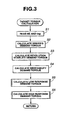
- Fig. 3 shows a calculation routine of a target torque (an engine operation torque required to finally achieve a driver's demand torque) executed in the preferred embodiment.
- a step S1 the CPU of the controller 7 reads the first operating variable ⁇ ap of the accelerator 2 and engine speed NE derived on the basis of the signal from the crank angle sensor 5.
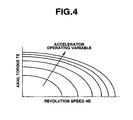
- the controller 7 calculates the driver's demand torque on the basis of the first operating variable ⁇ ap and the engine speed Ne read at the step S1.
- the CPU of the controller 7 retrieves the driver's demand torque from a map of Fig. 4 based on the experimental data.
- the CPU of the controller 7 calculates a torque demanded according to an operating condition of an engine accessory to stabilize an engine revolution (hereinafter, also called a revolution stability demand torque) (as will be described later).
- the CPU of the controller 7 calculates a torque demanded in terms of a vehicular driveability and safety (hereinafter, also referred to as driveability demand torque) (as will be described later).
- the CPU of the controller 7 calculates a (relatively) low response demand torque which is operated by the air quantity from among each demand torque.
- a priority order (precedence) of demand is allocated to the driveability demand torque (for example, a securing of the safety is a first priority order and a securing of the driveability is a second priority order) and the CPU of the controller 7 calculates the low response demand torque to be achieved in accordance with the priority order.
- a low response torque operation refers to an operation on, e.g., the air quantity to operate the engine generation torque in order to respond to a slow variation in the demand torque or in order to achieve the demand torque in a steady-state mode and to such a characteristic that a responsive characteristic is low due to an influence such as an intake air charge delay and a favorable follow-up to a transient torque variation cannot be made.
- the CPU of the controller 7 synthesizes the revolution stability demand torque and the driveability demand torque to calculate a (relatively) high response demand torque to correct a fuel injection quantity (fuel supply quantity) and an ignition timing.
- a high response torque operation refers to, for example, an operation on the fuel supply quantity and the ignition timing or only the fuel supply quantity to perform a torque operation having a favorable response characteristic so as to, e.g., respond to an instantaneous torque variation demand or so as to compensate for a response delay in the air component in the low response demand torque operation.
- a slight variation in the demand torque is not dependent upon the low response torque operation but is dependent upon the operation for the operated object on the high response demand torque operation (for example, the fuel supply (injection) quantity and the ignition timing).
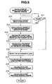
- Fig. 5 shows a calculation routine (step S3 in Fig. 3) on the revolution stability demand torque executed in the preferred embodiment.
- revolution stability demand torque is included in an external demand torque in the preferred embodiment.
- the CPU of the controller 7 determines whether the engine 4 falls in an idling condition from the present engine operating condition derived on the basis of detection signals of the respective sensors described above (,e.g., the opening angle of the throttle valve 11).
- the CPU of the controller 7 calculates a target revolution speed during the engine idling condition.
- the CPU of the controller 7 calculates a target intake air quantity (an intake air quantity to maintain the target revolution speed during the engine idling) required to maintain the engine speed NE at the target revolution speed.
- the CPU of the controller 7 retrieves the target intake air quantity from a map (a two-dimensional array) of the target intake air quantity with respect to the engine speed NE and the coolant temperature.
- the CPU of the controller 7 calculates a deviation between an actual revolution speed and the target revolution speed derived at the step S12.
- the CPU of the controller 7 calculates a feedback correction variable of the intake air quantity (also referred to as a revolution speed feedback correction variable) so as to become the actual revolution speed coincident with the target revolution speed according to the deviation in revolution speed.
- a feedback correction variable of the intake air quantity also referred to as a revolution speed feedback correction variable
- the CPU of the controller 7 determines whether any one or more of accessory loads such as an air conditioner, a power assisted steering system, and other electrical loads are being operated.
- the CPU of the controller 7 calculates a torque required to correct the accessory load according to the present engine operating condition on the basis of a determination result of the operation condition of any one or more of the accessory loads at the step S16.
- the CPU of the controller 7 calculates the demand torque for the revolution speed stabilization on the basis of an intake air quantity which is the addition of both of the target revolution speed maintaining intake air quantity and the revolution speed feedback correction variable and the torque required to correct the accessory load.
- the CPU of the controller 7 calculates an intake air quantity which is the sum of the target revolution speed maintaining intake air quantity and the revolution speed feedback correction variable and multiplies the calculation value by a coefficient to derive a torque correspondence value. Since, during the engine idling, the intake air quantity has a linear correlation to the engine torque, it is possible to calculate the demand torque described above in the above-described procedure.
- the CPU of the controller 7 sums the value of the intake air quantity converted torque and that of the accessory load correction torque to determine the demanded torque to stabilize the revolution speed.
- This revolution stability demand torque is a steady state demand torque, viz., the low response demand torque to be achieved by the low response torque operation.
- the CPU of the controller 7 calculates the high response demand torque to respond to the instantaneous torque variation demand.
- the CPU of the controller 7 calculates a value with a delay element in the intake air system provided (for example, a weight mean processing) and drives a difference between the low response demand torque and the value to determine the high response demand torque.
- the correction of the torque is made in terms of the good responsive fuel supply (injection) quantity and ignition timing.
- Fig. 6 shows an operational flowchart of the controller 7 (step S4 in Fig. 3) to calculate the driveability demand torque.
- the driveability demand torque is included in the external demand torque.
- the CPU of the controller 7 calculates a demand to correct a torque stepwise difference (a torque stepwise difference correction demand).
- the CPU of the controller 7 calculates a demand of an absolute value of the torque.
- the CPU of the controller 7 calculates the demand of the absolute value of the torque from a vehicular side although, in a traction control, the torque is operated so as to suppress a slip rate within a certain limit value with a slip rate on a driven wheel detected.
- the traction control system is exemplified by a United States Patent No. 5,566,776.
- the vehicular demand torque during the traction control is derived according to a retrieval of a table on the basis of the detected slip rate of the driven wheel with previously derived target torque with respect to the slip of the driven wheel arranged in the table.
- the CPU of the controller 7 selects one of the driveability demand calculated at the steps S21 and S23 whose torque operating width is larger so as to calculate the low response demand torque operated from the air quantity.
- the CPU of the controller 7 calculates the high response demand torque so as to compensate for the air response delay of the low response demand torque with respect to the target torque derived in Fig. 3.
- Fig. 7 shows a control routine of the torque operation to realize the low response demand torque.
- the CPU of the controller 7 reads the calculated low response demand torque.
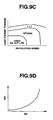
- the CPU of the controller 7 calculates a basic air quantity (intake air quantity) tTPst per cycle required to generate a combustion of fuel at the stoichiometric air-fuel mixture ratio (1 at an excess air ratio) on the basis of the low response demand torque read at the step S31.
- the basic air quantity tTPst may be retrieved from a map shown in Fig. 9B on the basis of the target torque (in this case, the low response demand torque) and the engine speed (NE).
- the CPU of the controller 7 calculates the target air-fuel mixture ratio to be set according to different engine operating conditions.
- the CPU of the controller 7 may retrieve the set target air-fuel mixture ratio from a map shown in Fig. 9C on the basis of the engine speed (NE) and the engine load (target torque, in this case, the low response demand torque).
- ⁇ denotes the excess air ratio.
- the CPU of the controller 7 calculates a target EGR (Exhaust Gas Recirculation) rate to be set according to the different engine operating conditions.
- EGR exhaust Gas Recirculation
- the CPU of the controller 7 may retrieve the target EGR rate from a map on the basis of the engine speed (NE) and the target torque.
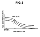
- the CPU of the controller 7 calculates a correction rate ⁇ f according to the air-fuel mixture ratio and the EGR rate since the fuel consumption rate is different according to the air-fuel mixture ratio and EGR rate.
- the fuel consumption rate is increased due to a reduction in a pumping loss and a reduction in a heat loss and the fuel consumption rate is improved up to a combustion stability limit.
- the CPU of the controller 7 may convert the correction rate into a ratio of 1 : n f when the fuel consumption rate (combustion efficiency) during the stoichiometric air-fuel mixture ratio is 1 and may retrieve the correction rate ⁇ f from a map generated on the basis of these data.
- the CPU of the controller 7 calculates an opening area Ath of the throttle valve 11 according to the target air quantity tTP derived at the step S36.
- the CPU of the controller 7 retrieves the opening area Ath from a map on the basis of the target air quantity tTP and the engine speed (NE).
- the CPU of the controller 7 calculates an opening angle ⁇ th of the throttle valve 11 according to the opening area Ath of the throttle valve 11.
- the CPU of the controller 7 retrieves the opening angle ⁇ th from a map representing a correlation of the opening angle ⁇ th to the opening area Ath determined according to a shape and a dimension of a throttle body for each product.
- the CPU of the controller 7 outputs the opening angle ⁇ th of the throttle valve 11 derived at the step S38 to the throttle valve controller 12.
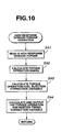
- Fig. 10 shows a control routine of the other torque operation to realize the high response demand torque.
- the CPU of the controller 7 reads the high response demand torque.
- the CPU of the controller 7 shares (separates) the read high response demand torque into a component operated from the fuel supply (injection) quantity and a component operated from the ignition timing.
- the CPU of the controller 7 calculates a correction variable with respect to a based injection quantity on the basis of the operation from the fuel supply (injection) quantity from among the high response demand torque.
- the based injection quantity refers to a set variable through a conventional method so as to enable the achievement of the target air-fuel mixture ratio by the target air quantity tTP.
- ⁇ is set to a predetermined value (for example, 1.0).
- the CPU of the controller 7 calculates a correction variable with respect to a based ignition timing on the basis of the operation from the ignition timing from among the high response demand torque.
- the based ignition timing is set on the basis of the engine speed, the engine load, and the target air-fuel mixture ratio.
- the controller 7 drives the fuel injection valves 8 and the ignition plugs 9 with the correction variables to the based fuel supply (injection) quantity calculated at the step S43 and to the based ignition timing calculated at the step S44 taken into consideration.
- Figs. 11A through 11E integrally show an example of the torque operation carried out in the preferred embodiment.
- the controller 7 controls the opening angle of the throttle valve 11 according to the driver's demand of torque increment (namely, the low response torque operation) so as to realize the target torque.
- the accessory load such as the air conditioner is operated and an corrective control is carried out
- the torque corresponding to the accessory load is reduced and the driver receives a shock of the torque reduction.
- the CPU of the controller 7 deems the value corresponding to the accessory load torque to be the low response demand torque, this being achieved by the air quantity operation (low response torque operation, namely, the throttle operation) to maintain the steady state target torque.
- the air quantity operation low response torque operation, namely, the throttle operation
- this is the high response demand torque and is compensated for the operations from the fuel supply (injection) quantity and from the ignition timing (the high response torque operation).
- the torque value corresponding to the torque reduction demand is deemed to be the low response target torque which is achieved by the air quantity operation to maintain the steady-state target value.
- the torque operation can be achieved according to the necessary load operation and external demand torque, it is possible to realize the torque that the driver demands without occurrence in the torque variation.
- the target torque is derived on the basis of the torque that the driver has demanded and the external demand torque such as the revolution speed stabilization torque and the torque demanded in terms of the vehicular driveability and safety (the target torque is calculated so as to satisfy every demand), the intake air quantity is operated so as to achieve the target torque and the fuel injection quantity and the ignition timing are operated so as to compensate for the response delay in the operation on the intake air quantity.
- the torque demanded in terms of the revolution speed stability can be achieved with high accuracy by means of cooperative (harmonious) controls of the air quantity, fuel supply quantity, and the ignition timing, all of the driver's intention to drive the vehicle, the stability during the idling, and the vehicular driveability can be satisfied.
- the present teaching is applicable to a mechanical device in which the throttle valve is mechanically linked to the vehicular operation through, in the preferred embodiment, the electronical servo device 12 in which a DC motor drives the throttle valve 11 is exemplified as shown in Fig. 1A.
- an auxiliary air passage bypassing the throttle valve and an auxiliary air valve installed in the auxiliary air passage are disposed in the intake air system of the engine.
- the same advantage as the case of the electronic servo device 12 can be achieved by controlling the auxiliary air valve so as to eliminate a deviation between a total opening area to realize the target air quantity calculated in the same way as the electronic servo device and the opening area of the actually mechanically controlled throttle valve.
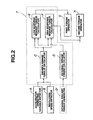
- Fig. 2 shows a functional block diagram of the control apparatus according to the present teaching.
- the accelerator operating variable detector A detects the operating variable of the accelerator 2 operated by the driver
- the revolution speed detector B detects the revolution speed (NE) of the engine
- the driver's demand calculator C calculates the engine torque demanded by the vehicle driver on the basis of the detected operating variable of the accelerator and the detected revolution speed as the driver's demand torque
- the external demand torque calculator D calculates the correction variable for the engine torque demanded from the external to the engine as the external demand torque
- the (relatively) low response torque demand torque calculator E calculates the (relatively) low response demand torque on the basis of at least one of the driver's demand torque and the external demand torque
- the (relatively) high response demand torque calculator F calculates the (relatively) high response demand torque on the basis of at least one of the driver's demand torque and the external demand torque
- the first torque operator G operates at least one object to be controlled in the (relatively) low response type so as to realize the calculated (relatively) low response demand torque
- the second torque operator H
Landscapes
- Engineering & Computer Science (AREA)
- Chemical & Material Sciences (AREA)
- Combustion & Propulsion (AREA)
- Mechanical Engineering (AREA)
- General Engineering & Computer Science (AREA)
- Electrical Control Of Air Or Fuel Supplied To Internal-Combustion Engine (AREA)
- Combined Controls Of Internal Combustion Engines (AREA)
- Electrical Control Of Ignition Timing (AREA)
Applications Claiming Priority (3)
| Application Number | Priority Date | Filing Date | Title |
|---|---|---|---|
| JP23225797 | 1997-08-28 | ||
| JP23225797A JP3627464B2 (ja) | 1997-08-28 | 1997-08-28 | エンジンの制御装置 |
| JP232257/97 | 1997-08-28 |
Publications (3)
| Publication Number | Publication Date |
|---|---|
| EP0899439A2 EP0899439A2 (en) | 1999-03-03 |
| EP0899439A3 EP0899439A3 (en) | 2001-12-05 |
| EP0899439B1 true EP0899439B1 (en) | 2005-10-12 |
Family
ID=16936442
Family Applications (1)
| Application Number | Title | Priority Date | Filing Date |
|---|---|---|---|
| EP98115465A Expired - Lifetime EP0899439B1 (en) | 1997-08-28 | 1998-08-17 | Control apparatus and method for internal combustion engine |
Country Status (5)
| Country | Link |
|---|---|
| US (1) | US6155230A (ko) |
| EP (1) | EP0899439B1 (ko) |
| JP (1) | JP3627464B2 (ko) |
| KR (1) | KR100287665B1 (ko) |
| DE (1) | DE69831840T2 (ko) |
Families Citing this family (82)
| Publication number | Priority date | Publication date | Assignee | Title |
|---|---|---|---|---|
| JP3414318B2 (ja) * | 1999-04-28 | 2003-06-09 | トヨタ自動車株式会社 | 内燃機関の燃焼制御装置 |
| JP2000352347A (ja) * | 1999-06-09 | 2000-12-19 | Suzuki Motor Corp | エンジン制御装置 |
| FR2804472B1 (fr) * | 2000-02-02 | 2002-07-26 | Sagem | Procede et dispositif de pilotage d'un debit de gaz passant par un organe d'etranglement |
| US6497212B2 (en) * | 2000-02-10 | 2002-12-24 | Denso Corporation | Control apparatus for a cylinder injection type internal combustion engine capable of suppressing undesirable torque shock |
| US6226585B1 (en) * | 2000-04-18 | 2001-05-01 | Ford Global Technologies, Inc. | Torque estimation method for an internal combustion engine |
| GB2368924B (en) * | 2000-09-26 | 2004-12-15 | Ford Global Tech Inc | A method and apparatus for controlling a powertrain |
| EP1234964A1 (fr) * | 2001-02-20 | 2002-08-28 | Sagem S.A. | Procédé et dispositif de pilotage d'un débit de gaz passant par un organe d'étranglement |
| DE10141600A1 (de) * | 2001-08-24 | 2003-03-06 | Bosch Gmbh Robert | Verfahren und Vorrichtung zur Steuerung einer Brennkraftmaschine eines Fahrzeugs |
| JP2002371881A (ja) * | 2001-06-13 | 2002-12-26 | Mitsubishi Electric Corp | スロットル制御装置 |
| DE10129448A1 (de) * | 2001-06-19 | 2003-01-02 | Bosch Gmbh Robert | Verfahren und Vorrichtung zur Überwachung einer Antriebseinheit eines Fahrzeugs und/oder ihr zugeordneter Komponenten |
| US6920865B2 (en) | 2002-01-29 | 2005-07-26 | Daimlerchrysler Corporation | Mechatronic vehicle powertrain control system |
| DE10204129B4 (de) * | 2002-02-01 | 2007-03-01 | Robert Bosch Gmbh | Verfahren und Vorrichtung zum Steuern einer Antriebseinheit mit einem Verbrennungsmotor |
| KR100471223B1 (ko) * | 2002-05-09 | 2005-03-08 | 현대자동차주식회사 | 엔진 아이들 회전수 제어방법 및 장치 |
| DE10225448A1 (de) * | 2002-06-08 | 2003-12-18 | Bosch Gmbh Robert | Verfahren und Vorrichtung zur Steuerung der Brennkraftmaschine eines Fahrzeugs |
| DE10246058B4 (de) * | 2002-10-02 | 2016-10-13 | Robert Bosch Gmbh | Verfahren und Vorrichtung zur Regelung einer Ausgangsgröße einer Antriebseinheit eines Fahrzeugs |
| US20030226528A1 (en) * | 2002-12-31 | 2003-12-11 | Hitachi, Ltd. | Compression ignition internal combustion engine |
| JP4443839B2 (ja) * | 2003-02-12 | 2010-03-31 | 本田技研工業株式会社 | 内燃機関の制御装置 |
| JP4120523B2 (ja) * | 2003-07-31 | 2008-07-16 | 日産自動車株式会社 | 内燃機関の排気還流制御装置 |
| WO2005017336A1 (ja) * | 2003-08-13 | 2005-02-24 | Hitachi, Ltd. | 内燃機関の制御装置 |
| DE102004060527A1 (de) * | 2004-12-16 | 2006-06-22 | Robert Bosch Gmbh | Verfahren und Vorrichtung zur Steuerung einer Antriebseinheit |
| JP3960339B2 (ja) * | 2005-01-11 | 2007-08-15 | トヨタ自動車株式会社 | 吸入空気量ばらつき検出装置 |
| DE102005000006A1 (de) * | 2005-01-24 | 2006-07-27 | Deere & Company, Moline | Getriebesteuerung für ein Getriebe eines Antriebsstrangs eines Arbeitsfahrzeugs |
| JP4466539B2 (ja) * | 2005-11-08 | 2010-05-26 | トヨタ自動車株式会社 | 内燃機関の制御装置 |
| JP4339321B2 (ja) * | 2006-01-20 | 2009-10-07 | 本田技研工業株式会社 | 内燃機関の制御装置 |
| JP2007237775A (ja) * | 2006-03-06 | 2007-09-20 | Mitsubishi Fuso Truck & Bus Corp | ハイブリッド電気自動車の制御装置 |
| JP2007297992A (ja) * | 2006-05-01 | 2007-11-15 | Toyota Motor Corp | 内燃機関の制御装置 |
| JP4775166B2 (ja) * | 2006-08-10 | 2011-09-21 | トヨタ自動車株式会社 | 内燃機関の制御装置 |
| JP4483885B2 (ja) * | 2007-03-29 | 2010-06-16 | トヨタ自動車株式会社 | 内燃機関の制御装置 |
| JP2009041528A (ja) * | 2007-08-10 | 2009-02-26 | Toyota Motor Corp | 内燃機関の制御装置 |
| JP4396748B2 (ja) * | 2007-08-21 | 2010-01-13 | トヨタ自動車株式会社 | 内燃機関の制御装置 |
| JP4862792B2 (ja) * | 2007-09-12 | 2012-01-25 | トヨタ自動車株式会社 | 駆動ユニットの制御装置 |
| US7698049B2 (en) * | 2008-01-09 | 2010-04-13 | Gm Global Technology Operations, Inc. | Speed control in a torque-based system |
| JP4875663B2 (ja) * | 2008-05-29 | 2012-02-15 | 株式会社クボタ | 作業車のアクセル制御構造 |
| US20090319146A1 (en) * | 2008-06-20 | 2009-12-24 | Graham Toby E | Traction control system for diesel powered vehicles |
| JP5092956B2 (ja) * | 2008-07-17 | 2012-12-05 | マツダ株式会社 | 車両用の内燃機関を制御する方法及び内燃機関システム |
| JP5171799B2 (ja) * | 2008-12-18 | 2013-03-27 | 日産自動車株式会社 | ベルト式無段変速機の制御装置 |
| JP5120275B2 (ja) * | 2009-01-23 | 2013-01-16 | トヨタ自動車株式会社 | 内燃機関の制御装置 |
| US8744716B2 (en) * | 2009-12-16 | 2014-06-03 | GM Global Technology Operations LLC | Speed control systems and methods for internal combustion engines |
| US8744727B2 (en) | 2010-05-13 | 2014-06-03 | Toyota Jidosha Kabushiki Kaisha | Control device for internal combustion engine |
| WO2012032618A1 (ja) | 2010-09-08 | 2012-03-15 | トヨタ自動車株式会社 | 内燃機関の制御装置 |
| JP5299394B2 (ja) * | 2010-10-01 | 2013-09-25 | 三菱自動車工業株式会社 | エンジンの制御装置 |
| JP5293717B2 (ja) * | 2010-10-01 | 2013-09-18 | 三菱自動車工業株式会社 | エンジンの制御装置 |
| JP5742648B2 (ja) * | 2011-10-13 | 2015-07-01 | 三菱自動車工業株式会社 | エンジンの制御装置 |
| JP5835078B2 (ja) * | 2012-04-19 | 2015-12-24 | トヨタ自動車株式会社 | 内燃機関の制御装置 |
| US9534547B2 (en) * | 2012-09-13 | 2017-01-03 | GM Global Technology Operations LLC | Airflow control systems and methods |
| US9399959B2 (en) | 2014-03-26 | 2016-07-26 | GM Global Technology Operations LLC | System and method for adjusting a torque capacity of an engine using model predictive control |
| US9784198B2 (en) | 2015-02-12 | 2017-10-10 | GM Global Technology Operations LLC | Model predictive control systems and methods for increasing computational efficiency |
| US9376965B2 (en) | 2013-04-23 | 2016-06-28 | GM Global Technology Operations LLC | Airflow control systems and methods using model predictive control |
| US9605615B2 (en) | 2015-02-12 | 2017-03-28 | GM Global Technology Operations LLC | Model Predictive control systems and methods for increasing computational efficiency |
| US9388754B2 (en) | 2014-03-26 | 2016-07-12 | GM Global Technology Operations LLC | Artificial output reference for model predictive control |
| US9388758B2 (en) | 2014-03-26 | 2016-07-12 | GM Global Technology Operations LLC | Model predictive control systems and methods for future torque changes |
| US9429085B2 (en) | 2013-04-23 | 2016-08-30 | GM Global Technology Operations LLC | Airflow control systems and methods using model predictive control |
| US9435274B2 (en) | 2014-03-26 | 2016-09-06 | GM Global Technology Operations LLC | System and method for managing the period of a control loop for controlling an engine using model predictive control |
| US9797318B2 (en) | 2013-08-02 | 2017-10-24 | GM Global Technology Operations LLC | Calibration systems and methods for model predictive controllers |
| US9714616B2 (en) | 2014-03-26 | 2017-07-25 | GM Global Technology Operations LLC | Non-model predictive control to model predictive control transitions |
| US9587573B2 (en) | 2014-03-26 | 2017-03-07 | GM Global Technology Operations LLC | Catalyst light off transitions in a gasoline engine using model predictive control |
| US9378594B2 (en) | 2014-03-26 | 2016-06-28 | GM Global Technology Operations LLC | Fault diagnostic systems and methods for model predictive control |
| US9920697B2 (en) | 2014-03-26 | 2018-03-20 | GM Global Technology Operations LLC | Engine control systems and methods for future torque request increases |
| US9528453B2 (en) | 2014-11-07 | 2016-12-27 | GM Global Technologies Operations LLC | Throttle control systems and methods based on pressure ratio |
| US9863345B2 (en) | 2012-11-27 | 2018-01-09 | GM Global Technology Operations LLC | System and method for adjusting weighting values assigned to errors in target actuator values of an engine when controlling the engine using model predictive control |
| US9732688B2 (en) | 2014-03-26 | 2017-08-15 | GM Global Technology Operations LLC | System and method for increasing the temperature of a catalyst when an engine is started using model predictive control |
| US9599053B2 (en) | 2014-03-26 | 2017-03-21 | GM Global Technology Operations LLC | Model predictive control systems and methods for internal combustion engines |
| US9765703B2 (en) | 2013-04-23 | 2017-09-19 | GM Global Technology Operations LLC | Airflow control systems and methods using model predictive control |
| US9599049B2 (en) | 2014-06-19 | 2017-03-21 | GM Global Technology Operations LLC | Engine speed control systems and methods |
| US9541019B2 (en) | 2014-03-26 | 2017-01-10 | GM Global Technology Operations LLC | Estimation systems and methods with model predictive control |
| US9334815B2 (en) | 2014-03-26 | 2016-05-10 | GM Global Technology Operations LLC | System and method for improving the response time of an engine using model predictive control |
| US9126580B2 (en) * | 2013-09-05 | 2015-09-08 | Ford Global Technologies, Llc | Method and system for operating vehicle accessories |
| GB2519602B (en) * | 2013-10-28 | 2018-08-29 | Jaguar Land Rover Ltd | Method of Optimising Idling of an Internal Combustion Engine |
| DE102017000732A1 (de) * | 2016-02-12 | 2017-08-17 | Mazda Motor Corporation | Motorsteuerung bzw. Regelung |
| US9938908B2 (en) | 2016-06-14 | 2018-04-10 | GM Global Technology Operations LLC | System and method for predicting a pedal position based on driver behavior and controlling one or more engine actuators based on the predicted pedal position |
| US9789876B1 (en) | 2016-06-16 | 2017-10-17 | GM Global Technology Operations LLC | Axle torque control system for a motor vehicle |
| JP6836929B2 (ja) * | 2017-02-16 | 2021-03-03 | 三菱重工業株式会社 | エンジン出力推定装置及び方法 |
| US10125712B2 (en) | 2017-02-17 | 2018-11-13 | GM Global Technology Operations LLC | Torque security of MPC-based powertrain control |
| US10119481B2 (en) | 2017-03-22 | 2018-11-06 | GM Global Technology Operations LLC | Coordination of torque interventions in MPC-based powertrain control |
| US10399574B2 (en) | 2017-09-07 | 2019-09-03 | GM Global Technology Operations LLC | Fuel economy optimization using air-per-cylinder (APC) in MPC-based powertrain control |
| US10358140B2 (en) | 2017-09-29 | 2019-07-23 | GM Global Technology Operations LLC | Linearized model based powertrain MPC |
| US10619586B2 (en) | 2018-03-27 | 2020-04-14 | GM Global Technology Operations LLC | Consolidation of constraints in model predictive control |
| US10661804B2 (en) | 2018-04-10 | 2020-05-26 | GM Global Technology Operations LLC | Shift management in model predictive based propulsion system control |
| US10859159B2 (en) | 2019-02-11 | 2020-12-08 | GM Global Technology Operations LLC | Model predictive control of torque converter clutch slip |
| US11312208B2 (en) | 2019-08-26 | 2022-04-26 | GM Global Technology Operations LLC | Active thermal management system and method for flow control |
| US11008921B1 (en) | 2019-11-06 | 2021-05-18 | GM Global Technology Operations LLC | Selective catalytic reduction device control |
| JP7251461B2 (ja) * | 2019-12-13 | 2023-04-04 | トヨタ自動車株式会社 | 制御システム |
Family Cites Families (15)
| Publication number | Priority date | Publication date | Assignee | Title |
|---|---|---|---|---|
| JPS5650232A (en) * | 1979-09-28 | 1981-05-07 | Nissan Motor Co Ltd | Controlling device for fuel |
| JPH0737771B2 (ja) * | 1984-02-07 | 1995-04-26 | 日産自動車株式会社 | スロツトル制御装置 |
| JPH0625545B2 (ja) * | 1987-12-28 | 1994-04-06 | 株式会社日立製作所 | 内燃機関の電子スロツトル制御装置 |
| JPH04101037A (ja) | 1990-08-16 | 1992-04-02 | Nissan Motor Co Ltd | 車両用内燃機関の制御装置 |
| DE4141947C2 (de) * | 1991-12-19 | 2002-02-07 | Bosch Gmbh Robert | Steuersystem für eine Antriebseinheit in einem Flugzeug |
| JP3158848B2 (ja) * | 1994-03-16 | 2001-04-23 | 日産自動車株式会社 | 車両用トラクション制御装置 |
| JP3448995B2 (ja) * | 1994-12-01 | 2003-09-22 | 日産自動車株式会社 | 車両の駆動力制御装置 |
| DE19517675B4 (de) * | 1995-05-13 | 2006-07-13 | Robert Bosch Gmbh | Verfahren und Vorrichtung zur Steuerung des Drehmoments einer Brennkraftmaschine |
| JP3324344B2 (ja) * | 1995-07-18 | 2002-09-17 | 日産自動車株式会社 | 内燃機関のアイドル回転速度制御装置 |
| JP3510036B2 (ja) | 1996-02-22 | 2004-03-22 | 株式会社ルネサステクノロジ | 半導体装置の製造方法 |
| US5755202A (en) * | 1996-10-25 | 1998-05-26 | Ford Global Technologies, Inc. | Method of reducing feed gas emissions in an internal combustion engine |
| JP3356945B2 (ja) * | 1996-12-17 | 2002-12-16 | 愛三工業株式会社 | スロットルバルブ制御装置 |
| JP3514077B2 (ja) * | 1997-06-24 | 2004-03-31 | 日産自動車株式会社 | エンジンのスロットル制御装置 |
| KR100317157B1 (ko) * | 1997-07-04 | 2002-02-19 | 하나와 요시카즈 | 내연기관용제어시스템 |
| JPH1144241A (ja) * | 1997-07-30 | 1999-02-16 | Nissan Motor Co Ltd | 内燃機関のアイドル回転速度制御装置 |
-
1997
- 1997-08-28 JP JP23225797A patent/JP3627464B2/ja not_active Expired - Lifetime
-
1998
- 1998-08-17 EP EP98115465A patent/EP0899439B1/en not_active Expired - Lifetime
- 1998-08-17 DE DE69831840T patent/DE69831840T2/de not_active Expired - Lifetime
- 1998-08-27 KR KR1019980034830A patent/KR100287665B1/ko not_active IP Right Cessation
- 1998-08-28 US US09/143,368 patent/US6155230A/en not_active Expired - Lifetime
Also Published As
| Publication number | Publication date |
|---|---|
| EP0899439A3 (en) | 2001-12-05 |
| KR100287665B1 (ko) | 2001-05-02 |
| DE69831840D1 (de) | 2006-02-23 |
| EP0899439A2 (en) | 1999-03-03 |
| KR19990023930A (ko) | 1999-03-25 |
| US6155230A (en) | 2000-12-05 |
| DE69831840T2 (de) | 2006-05-11 |
| JP3627464B2 (ja) | 2005-03-09 |
| JPH1162690A (ja) | 1999-03-05 |
Similar Documents
| Publication | Publication Date | Title |
|---|---|---|
| EP0899439B1 (en) | Control apparatus and method for internal combustion engine | |
| US6000376A (en) | Method and device for controlling and internal combustion engine | |
| EP1982063B1 (en) | Control apparatus for vehicle | |
| US6704641B2 (en) | Automotive integrated control system | |
| US7444225B2 (en) | Engine power controlling apparatus and method | |
| US8209106B2 (en) | Control apparatus for internal combustion engine | |
| US6086510A (en) | Engine-output control unit | |
| US5904128A (en) | Cylinder fuel injection engine controller | |
| WO1993022550A1 (en) | Method for controlling the number of revolutions of internal combustion engine at an idle | |
| JP3880618B2 (ja) | 内燃機関の制御方法および装置 | |
| US20100191406A1 (en) | Control apparatus for vehicle drive unit | |
| JPH08144820A (ja) | 内燃エンジンのスロットル弁制御装置 | |
| JPH07208309A (ja) | 内燃機関制御方法及び装置 | |
| JP3641914B2 (ja) | 内燃機関の制御装置 | |
| KR100749193B1 (ko) | 차량의 구동 유닛 제어를 위한 장치 및 방법 | |
| US20140360464A1 (en) | Internal combustion engine control device | |
| JP3759975B2 (ja) | アイドリング中の自動車の駆動装置の回転速度を調整するための方法及び装置 | |
| JPH1030469A (ja) | 内燃機関の制御方法及び装置 | |
| US5964202A (en) | Controlling apparatus for throttle valve and for driving in internal combustion engine | |
| JP3294894B2 (ja) | 車両の退避走行装置 | |
| JP2660624B2 (ja) | 内燃機関のアイドル回転速度制御装置 | |
| JP2660623B2 (ja) | 内燃機関のアイドル回転速度制御装置 | |
| JPH0323326A (ja) | エンジンのアイドル回転数制御装置 | |
| JPH02130244A (ja) | 機関回転数の制御装置 | |
| JPH05321730A (ja) | 内燃機関の回転数制御装置 |
Legal Events
| Date | Code | Title | Description |
|---|---|---|---|
| PUAI | Public reference made under article 153(3) epc to a published international application that has entered the european phase |
Free format text: ORIGINAL CODE: 0009012 |
|
| 17P | Request for examination filed |
Effective date: 19980817 |
|
| AK | Designated contracting states |
Kind code of ref document: A2 Designated state(s): AT BE CH CY DE DK ES FI FR GB GR IE IT LI LU MC NL PT SE Kind code of ref document: A2 Designated state(s): DE FR GB |
|
| AX | Request for extension of the european patent |
Free format text: AL;LT;LV;MK;RO;SI |
|
| PUAL | Search report despatched |
Free format text: ORIGINAL CODE: 0009013 |
|
| AK | Designated contracting states |
Kind code of ref document: A3 Designated state(s): AT BE CH CY DE DK ES FI FR GB GR IE IT LI LU MC NL PT SE |
|
| AX | Request for extension of the european patent |
Free format text: AL;LT;LV;MK;RO;SI |
|
| AKX | Designation fees paid |
Free format text: DE FR GB |
|
| 17Q | First examination report despatched |
Effective date: 20040109 |
|
| GRAP | Despatch of communication of intention to grant a patent |
Free format text: ORIGINAL CODE: EPIDOSNIGR1 |
|
| GRAS | Grant fee paid |
Free format text: ORIGINAL CODE: EPIDOSNIGR3 |
|
| GRAA | (expected) grant |
Free format text: ORIGINAL CODE: 0009210 |
|
| AK | Designated contracting states |
Kind code of ref document: B1 Designated state(s): DE FR GB |
|
| REG | Reference to a national code |
Ref country code: GB Ref legal event code: FG4D |
|
| REF | Corresponds to: |
Ref document number: 69831840 Country of ref document: DE Date of ref document: 20060223 Kind code of ref document: P |
|
| ET | Fr: translation filed | ||
| PLBE | No opposition filed within time limit |
Free format text: ORIGINAL CODE: 0009261 |
|
| STAA | Information on the status of an ep patent application or granted ep patent |
Free format text: STATUS: NO OPPOSITION FILED WITHIN TIME LIMIT |
|
| 26N | No opposition filed |
Effective date: 20060713 |
|
| REG | Reference to a national code |
Ref country code: GB Ref legal event code: 746 Effective date: 20070604 |
|
| REG | Reference to a national code |
Ref country code: FR Ref legal event code: PLFP Year of fee payment: 19 |
|
| REG | Reference to a national code |
Ref country code: FR Ref legal event code: PLFP Year of fee payment: 20 |
|
| PGFP | Annual fee paid to national office [announced via postgrant information from national office to epo] |
Ref country code: FR Payment date: 20170714 Year of fee payment: 20 Ref country code: DE Payment date: 20170808 Year of fee payment: 20 Ref country code: GB Payment date: 20170816 Year of fee payment: 20 |
|
| REG | Reference to a national code |
Ref country code: DE Ref legal event code: R071 Ref document number: 69831840 Country of ref document: DE |
|
| REG | Reference to a national code |
Ref country code: GB Ref legal event code: PE20 Expiry date: 20180816 |
|
| PG25 | Lapsed in a contracting state [announced via postgrant information from national office to epo] |
Ref country code: GB Free format text: LAPSE BECAUSE OF EXPIRATION OF PROTECTION Effective date: 20180816 |