EP0899218A2 - Aufbewahrungsvorrichtung für Stangen - Google Patents
Aufbewahrungsvorrichtung für Stangen Download PDFInfo
- Publication number
- EP0899218A2 EP0899218A2 EP98119925A EP98119925A EP0899218A2 EP 0899218 A2 EP0899218 A2 EP 0899218A2 EP 98119925 A EP98119925 A EP 98119925A EP 98119925 A EP98119925 A EP 98119925A EP 0899218 A2 EP0899218 A2 EP 0899218A2
- Authority
- EP
- European Patent Office
- Prior art keywords
- bar
- pallet
- storage apparatus
- lifting
- bars
- Prior art date
- Legal status (The legal status is an assumption and is not a legal conclusion. Google has not performed a legal analysis and makes no representation as to the accuracy of the status listed.)
- Granted
Links
Images


Classifications
-
- B—PERFORMING OPERATIONS; TRANSPORTING
- B23—MACHINE TOOLS; METAL-WORKING NOT OTHERWISE PROVIDED FOR
- B23Q—DETAILS, COMPONENTS, OR ACCESSORIES FOR MACHINE TOOLS, e.g. ARRANGEMENTS FOR COPYING OR CONTROLLING; MACHINE TOOLS IN GENERAL CHARACTERISED BY THE CONSTRUCTION OF PARTICULAR DETAILS OR COMPONENTS; COMBINATIONS OR ASSOCIATIONS OF METAL-WORKING MACHINES, NOT DIRECTED TO A PARTICULAR RESULT
- B23Q7/00—Arrangements for handling work specially combined with or arranged in, or specially adapted for use in connection with, machine tools, e.g. for conveying, loading, positioning, discharging, sorting
- B23Q7/10—Arrangements for handling work specially combined with or arranged in, or specially adapted for use in connection with, machine tools, e.g. for conveying, loading, positioning, discharging, sorting by means of magazines
-
- B—PERFORMING OPERATIONS; TRANSPORTING
- B65—CONVEYING; PACKING; STORING; HANDLING THIN OR FILAMENTARY MATERIAL
- B65G—TRANSPORT OR STORAGE DEVICES, e.g. CONVEYORS FOR LOADING OR TIPPING, SHOP CONVEYOR SYSTEMS OR PNEUMATIC TUBE CONVEYORS
- B65G1/00—Storing articles, individually or in orderly arrangement, in warehouses or magazines
- B65G1/02—Storage devices
- B65G1/04—Storage devices mechanical
- B65G1/0442—Storage devices mechanical for elongated articles
Definitions
- the present invention relates to a bar storage apparatus for storing bars to be supplied to a bar processing machine such as a sawing machine, and more specifically to a bar storage apparatus capable of storing a great number of bars of various sorts and further of facilitating conveyance of any required bars into and out of the bar processing machine, as well as a method of loading a bar from such a storage apparatus to a bar processing machine.
- a roller conveyor is arranged on the rear side of the bar processing machine; and a chain conveyor is disposed along a direction perpendicular to the bar feeding direction of the roller conveyor; and bars to be processed are mounted on the chain conveyor in accordance with the order of processing.
- U.S. Patent No. 4 362 454 cited above discloses a bar storage apparatus corresponding to the preamble part of claim 1. Such an apparatus has the advantage of being capable of storing a great number of bars.
- the bar supplying device comprises some grabs which have to be moved horizontally and vertically to load and unload the workpieces. These grabs have quite a complicated trajectory, which renders the operation time for conveying the bars rather long.
- the present invention seeks to remedy this drawback and to provide a bar storage apparatus capable of storing a great number of bars of various kinds, of selecting any required bars from a great number of bars, and of easily and quickly supplying the selected bars to a bar processing machine.
- the bar storage apparatus including the features of the preamble part of claim 1 is characterized in that the bar supplying device comprises a bar lifting device for lifting a bar mounted on the pallet located at the predetermined position, a bar conveying device for receiving the bar lifted by said bar lifting device and further conveying the received bar in a direction perpendicular to the bar longitudinal direction, and a bar feeding device for receiving the bar from said bar conveying device and further feeding the received bar in the bar longitudinal direction.
- a method of loading a bar from such an apparatus is also claimed.
- the pallet preferably has a lattice structure.
- the pallet is preferably provided with a plurality of vertical rollers for partitioning bar mounting positions, and said bar supplying device is slightly inclined to shift the bar into contact with the vertical rollers.
- the pallet may be formed with grooves each for stably supporting the bar.
- a pallet support table is preferably disposed on one side of said shelf frame opposite to the other side on which said elevator device is disposed, to support the pallet moved by said elevator device, the pallet support table being provided with a second traverser for moving the pallet.
- the bar supplying device advantageously includes a plurality of push rods aligned in a longitudinal direction of the bar to be supplied and spaced from each other by a suitable distance, each push rods being adapted to be moved in the vertical direction independently of each other.
- the bar conveying device advantageously includes a first bar supporting portion for supporting a new bar, and a second bar supporting portion for supporting a residual bar.
- the bar storage apparatus 1 of the present invention is disposed on the rear side of a bar processing machine 3 such as a band sawing machine.
- a cut-off workpiece conveying apparatus 5 is disposed to convey workpieces W cut off by the bar processing machine 3 from the cutting position of the bar processing machine 3 to the front side.
- the bar processing machine 3 is an ordinary well-known band sawing machine or a circular sawing machine, so that any detailed descriptions thereof are omitted.
- the cut-off workpiece conveying apparatus 5 is provided with such functions as to convey the cut-off workpieces W in the forward direction and further to sort and arrange the cut-off workpieces W according to the shapes and the dimensions thereof.
- a carriage 9 provided with a work clamp 7 for clamping the cut-off workpieces W is disposed along a guide frame 11 so as to be movable to and fro in the front and rear directions. Further, on one side of the passage along which the carriage 9 is moved to and fro, a stock table 13 is arranged to store the cut-off workpieces W temporarily.
- the cut-off workpieces W cut off by the bar processing machine 3 are conveyed in the forward direction and further stored temporarily on the stock table 13 according to the shapes and dimensions of the cut-off workpieces W.
- the cut-off workpieces W arranged on the stock table 13 are appropriately carried to another machine tool such as a lathe for the succeeding process.
- cut-off workpiece conveying apparatus 5 is not described in detail herein.
- the bar storage apparatus of the present invention is so constructed as to store a great number of bars of various kinds and various dimensions to be supplied to the bar processing machine 3, to supply any required bars from the storage position to the bar processing machine 3, and further to return the residual bars to the storage position.
- the bar storage apparatus 1 is composed roughly of a shelf frame 19, an elevator device 23 and a bar supplying device 25.
- the shelf frame 19 is provided with a plurality of pallet accommodating shelves 17 each for removably accommodating a pallet 15 on which a plurality of elongate bars B (including the shortened residual bars) are mounted.
- An elevator device 23 is disposed on one side of the shelf frame 19 so as to be movable up and down in the vertical direction and provided with a traverser 21 for moving the pallet 15 to and fro horizontally relative to the pallet accommodating shelf 17.
- the bar supplying device 25 supplies any required bar B arranged on the pallet 15 pulled out of the pallet accommodating shelf 17 and located at a predetermined position by the elevator device 23, to the bar processing machine 3.
- the pallet 15 is formed into an elongate lattice structure or shape extending in the front and rear direction by combining belt-shaped plates.
- a plurality of rollers 27 are rotatably arranged to move the pallet 15 smoothly.
- a hook 29 engageable from below is provided on one side of the right and left direction of the pallet 15.
- a plurality of vertical partition rollers 31 are arranged to partition the bar mounting space into plural bar mounting sections in the transverse direction (perpendicular to the longitudinal direction of bars).
- the shelf frame 19 is of parallelepiped structure constructed by a plurality of upright columns 33 standing at the corner portions of the base and a plurality of horizontal connecting beams 35 for connecting the respective upright columns 33. Further, the pallet shelf 17 is partitioned into a plurality of vertical stages by a plurality of pallet support rails 37 for connecting the respective upright columns 33 in the right and left direction.
- the elevator device 23 is disposed on the left side of the shelf frame 19 so as to be movable up and down.
- the elevator device 23 is of rectangular shape formed by connecting two front and rear elevator bases 41 by a connecting member 43.
- the two front and rear elevator bases 41 are guided in the vertical direction by a plurality of guide rollers 39 rotatable along the upright columns 33 of the shelf frame 19.
- An elevator operating device 45 is disposed on the upper portion of the shelf frame 19, in order to move the elevator device 23 in the vertical direction along the upright columns 33 of the shelf frame 19, as shown in Fig. 2.
- a drive sprocket 47 is rotatably attached to the upper portion of the shelf frame 19, and a driven sprocket 49 is rotatably attached to the lower portion of the shelf frame 19. Further, a loop-shaped chain 51 linked with the elevator device 23 is reeled around the drive sprocket 47 and the driven sprocket 49, respectively.
- An elevator motor 53 and a reduction gear 55 such as a worm reduction gear are mounted on the upper portion of the shelf frame 19.
- the elevator motor 53 and the reduction gear 55 are linked by an endless chain 57.
- the elevator device 23 can be easily stopped at a height position corresponding to the respective pallet accommodating shelf 17 of the shelf frame 19 as follows:
- appropriate sensors (not shown) or dogs are attached at the respective positions of the respective pallet accommodating shelves 17 of the shelf frame 19. Further, the similar dog or sensor is attached on the elevator device 23 in such a way that the vertical motion of the elevator device 23 can be stopped when the sensor is operated by the dog.
- a rotation detector such as a pulse encoder, for instance on the drive sprocket 47 or the elevator motor 53.
- the rotation detector detects the vertical position of the elevator device 23, that is, when the elevator device 23 is moved to a height corresponding to any required pallet accommodating shelf 17, the vertical motion of the elevator device 23 is stopped automatically.
- the traverser 21 for pulling out the pallet 15 from the pallet accommodating shelf 17 to the elevator device 23 and further for returning the pallet 15 from the elevator device 23 to the pallet accommodating shelf 17 can be constructed as follows:
- the traverser 21 is formed into a long shape extending in the front and rear direction.
- a plurality of guide rollers 61 are rotatably arranged so as to be guided by two guide rails 59 attached to the elevator device 23.
- a rotary shaft 65 driven by a motor 63 is provided for the traverser 21 so as to extend in the front and rear direction.
- Two pinions 67 are attached to both ends of the rotary shaft 65.
- the two pinions 67 are in mesh with two racks 69 provided for the elevator device 23 so as to extend in parallel to the guide rails 59 respectively.
- the traverser 21 can be moved to and fro along the guide rails 59.
- the traverser 21 is provided with a hook 71 movable up and down so as to be engaged with or disengaged from the hook 29 of the pallet 15.
- an actuator 73 such as an air cylinder is mounted on the traverser 21 to move the hook 71 up and down. Therefore, when this actuator 73 is actuated, the hook 71 can be moved up and down into engagement or disengagement from the hook 29 of the pallet 15.
- the motor 63 is driven to move the traverser 21 close to the pallet 15 in the pallet accommodating shelf 17; the actuator (cylinder) 73 is actuated to engage the hook 71 of the traverser 21 with the hook 29 of the pallet 15; and then the motor 63 is driven in the reverse direction to return the traverser 21 to the original position, so that it is possible to move any given pallet 15 from any required pallet accommodating shelf 17 onto the elevator device 23.
- the bar supplying device 25 is used to supply any required bar B on the pallet 15 to the bar processing machine 3.
- the bar supplying apparatus 25 is disposed on the right side of the shelf frame 19.
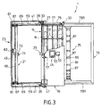
- a pallet passing shelf 17L is formed at the lowermost position of the shelf frame 19, to pass the pallet 15 therethrough in the right and left direction in Fig. 2.
- the pallet passing shelf 17L is provided with two guide rails 75 and two racks 77 (as shown in Fig. 3) operationally connectable to the guide rails 59 and the racks 69 of the elevator device 23, respectively, when the elevator device 23 is positioned at the same height as the pallet passing shelf 17L.
- a pallet support table 79 is installed on the right side of the shelf frame 19 of frame structure, as shown in Fig. 2.
- the pallet support table 79 is provided with two guide rails 79R operationally connectable to the two guide rails 75 of the pallet passing shelf 17L, as shown also in Fig. 3.
- the bar supplying device 25 is disposed within the pallet support table 79, in order to supply the bar B mounted on the pallet 15 supported on pallet support table 79 to the bar processing machine 3.
- the bar supplying device 25 is installed on the rear side of the bar processing machine 3 so that the bar B can be directly supplied to the bar processing machine 3.
- the bar storage apparatus of the present invention a great number of bars of various kinds can be stored; any required bars can be selected and supplied to the bar processing machine 3 automatically; and further the residual bar processed by the bar processing machine 3 can be stored again.
- the shelf frame 19 can be replenished with new bars B during a processing being effected in the bar B, thus enabling the automatization and the labor saving of the bar processing.
- Fig. 4 shows that the axis of the bar feeding roller 87 of the bar supplying device 25 is set horizontally (without being inclined slightly as in the first embodiment), and in addition the bar feeding roller 87 is replaced with a groove roller formed with a groove 87G in the outer circumferential surface thereof. Further, the pallet 15 is also formed with V grooves 15G for stably supporting the bars B, without using the vertical partition rollers 31.
- Fig. 5 shows the pallet 15 being provided with two hooks 29 on both right and left sides of the pallet 15, and further a second traverser 21A being additionally provided on the pallet support table 79 so as to be freely movable to and fro in the right and left direction.
- the second traverser 21A is arranged on the pallet support table 79 in symmetrical positional relationship with respect to the traverser 21 arranged on the elevator device 23. Since the function and the composing elements of the second traverser are the same as with the case of the traverser 21 of figure 1, the same reference numerals have been retained for the similar parts or elements. without repeating any detailed description thereof.
- first traverser 21 only to move the pallet 15 between one of the pallet accommodating shelves 17 and the pallet support table 79
- second traverser 21A only to locate the pallet 15 on the pallet support table 79 at an appropriate position corresponding to the bar processing machine 3.
- the first work is to move the elevator device 23 up and down, to pull out any required pallet 15 from the pallet accommodating shelf 17 onto the elevator device 23, to replenish the pallet 15 with new bars B, and to return the pallet 15 into the pallet accommodating shelf 17.
- the second work is to supply a plurality of bars B supported, through the pallet 15, on the pallet support table 79 to the bar processing machine 3.
- Fig. 6 shows the elevator device 23 being disposed on the right side of the shelf frame 19 so as to be movable up and down. Further, the partition rollers are omitted from the pallet 15. The pallet 15 is moved to and fro by engaging its hook 29 with the hook 71 of the traverser 21 to lift the side of the pallet 15 provided with the hook 29.
- the bar supplying device 25 comprises a bar lifting device 95 for lifting the bar B from the pallet 15 on the elevator device 23, and a bar feeding device 97 for feeding the bar B in the longitudinal direction of the bar B
- the bar lifting device 95 is composed of a plurality of lifting cylinders 99, an elongate lifting frame 101 moved up and down by the lifting cylinders 99, and a plurality of push rods 103 arranged vertically at regular intervals on the upper surface of the lifting frame 101. Further, a V-shaped groove is formed on the upper end surface of each of the push rods 103 to push up the bar B.
- the bar feeding device 97 is provided with an elongate frame 109 movable in the right and left direction. This bar feeding device 97 is supported by a guide rail 105 via a plurality of guide rollers 107.
- the guide rail 105 is fixed to the shelf frame 19 and extended in the right and left direction.
- a plurality of horizontal support rollers 111 of cantilever type are arranged at regular intervals so as to receive or support the bar B pushed up by the push rods 103. Further, a plurality of vertical rollers 113 are also arranged at regular intervals on the right side end of the movable frame 109.
- the pallet 15 is pulled out of any required pallet accommodating shelf 17 by the traverser 21, and moved downward to the lowermost position by the elevator device 23. Then, any required bar B on the pallet 15 is positioned over the bar lifting device 95 by the traverser 21.
- the lifting cylinder 99 of the bar lifting device 95 is actuated to lift the lifting frame 101, so that the bar B on the pallet 15 can be pushed up by a plurality of the push rods 103.
- the movable frame 109 of the bar feeding device 97 is shifted from the left side position to the right side as shown in Fig. 6, so that the horizontal support rollers 111 of the movable frame 109 are positioned under the bar B lifted by the bar lifting device 95.
- the lifted rod B can be supported by a plurality of the horizontal support rollers 111. Therefore, it is possible to feed and supply the bar B to the bar processing machine 3 by rotating the horizontal support rollers 111 with a motor (not shown). Further, it is possible to return the residual bar processed by the bar processing machine 3 to the pallet 15 by rotating the same motor in the reverse direction.
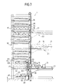
- Fig. 7 shows the elevator actuating device 45 being disposed on the lower portion of the shelf frame 19. Further, the bar lifting device 95 and the bar feeding device 97 are both disposed inside the shelf frame 19, respectively.
- the construction other than the above is the same as with the case of the figure 6, so that the same reference numerals have been retained for similar parts or elements which have the same functions, without repeating any detailed description thereof.
- the bar feeding device 97 is disposed inside the shelf frame 19; thus, after any required bar B has been moved to the bar feeding device 97 and further supplied to the bar processing machine 3, the following operation can be performed during the processing being made in the supplied bar B: to return the pallet 15 from the elevator device 23 to the original position (the pallet accommodating shelf 17) and further to prepare a new pallet 15 on the elevator device 23 or to replenish the shelf frame 19 with new bars.
- Fig. 8 shows an embodiment of the bar storage apparatus of the present invention.
- the bar supplying device 25 is composed of a bar lifting device 121 for lifting the bar B from the pallet 15, a bar conveying device 123 for receiving the bar B lifted by the bar lifting device 121 and further conveying the received bar B in a direction perpendicular to the longitudinal direction of the bar B, and a bar feeding device 125 for feeding the bar B toward the bar processing machine 3.
- the bar lifting device 121 has an elongate movable base 127 movable in the right and left direction in Fig. 8.
- the movable base 127 is provided with a plurality of rollers 129 at the lower portion thereof, and a plurality of push rods 131 at the upper portion; the plurality of push rods 131 are arranged at appropriate regular intervals in the longitudinal direction of the bar B.
- the bar conveying device 123 has a movable frame 135 movable along a guide rail 133 extending in the right and left direction.
- the movable frame 135 is provided with a fork-shaped bar receiving member 137 for receiving the bar B which is lifted by the bar push rods 131.
- the bar receiving member 137 can be moved up and down by a lifting cylinder 139.
- the bar feeding device 125 disposed inside the shelf frame 19 is composed of a base 141, a plurality of brackets 143 arranged vertically on the base 141 at regular intervals, and a support roller 145 and a vertical roller 147 both provided at the upper portion of each of the brackets 143, respectively.
- the bar lifting device 121 is moved in the right and left direction to such a position as to correspond to the required bar B on the pallet 15.
- the elevator device 23 is lowered to the lowermost position, since the lifting rods 131 project beyond the upper surface of the pallet 15, the required bar B is pushed upward relative to the pallet 15. Then, the bar conveying device 123 is moved to the position of the bar lifting device 121 so that the bar receiving member 137 is moved under the bar B. Thereafter, the bar receiving member 137 is lifted by the lifting cylinder 139 to receive the bar B on the bar receiving member 137.
- the bar conveying device 123 is returned to the position where the bar feeding device 125 is disposed.
- the bar receiving member 137 is lowered, so that the bar B can be mounted on the support rollers 145 of the bar feeding device 125. Therefore, it is possible to feed the bar B in the longitudinal direction toward the bar processing machine 3 by rotating the support rollers 145 of the bar feeding device 125.
- Fig. 9 shows a further embodiment of the bar storage apparatus according to the present invention.
- a lifting cylinder 149 is mounted on the movable base 127 of the bar lifting device 121 of figure 8 in order to move the bar push rods 131 up and down.
- the bar conveying device 123 and the bar feeding device 125 of figure 8 are combined and used in common. That is, the movable frame 135 of the bar conveying device 123 has a fork-shaped support member 151, and the support rollers 145 and the vertical rollers 147 are provided on the fork-shaped support member 151.
- the movable frame 135 is shifted to and located at the original position corresponding to the bar processing machine 3. Under these conditions, when the support rollers 145 are rotated, it is possible to supply the bar B to the bar processing machine 3.
- Fig. 10 shows a further embodiment of the bar storage apparatus of the present invention.
- a bar lifting device 153 is disposed at an appropriate position inside the shelf frame 19.
- a bar feeding device 155 is composed of a movable frame 159 movable along guide rails 157 fixed to the shelf frame 19 and extending in the right and left directions, an elongate lifting frame 163, a plurality of lifting cylinders 161 for moving the elongate lifting frame 163 up and down, and a plurality of horizontal support rollers 145 and a plurality of vertical support rollers 147 rotatably attached to the lifting frame 163, respectively.
- the bar lifting device 153 is composed of an elongate lifting frame 167 moved up and down by a plurality of lifting cylinders 165 and a plurality of lifting rods 169 arranged at regular intervals on the upper surface of the lifting frame 167.
- the pallet 15 on the elevator device 23 is moved into the shelf frame 19 along the guide rails 171, and located at such a position that a required bar B on the pallet 15 can be placed over the bar lifting device 153.
- the movable frame 159 is moved along the guide rails 157 so that the support rollers 145 can be moved under the bar B lifted by the push rods 169, and further the bar push rod 169 is lowered to pass the bar B to the support rollers 145. Subsequently, the movable frame 159 is returned to the original position, and the lifting frame 163 is moved up and down so that the height of the support rollers 145 corresponds to that of the bar processing machine 3. Thereafter, when the support rollers 145 are rotated, it is possible to feed and supply the bar B to the bar processing machine 3.
- Fig. 11 shows an other embodiment of the bar storage apparatus of the present invention.
- the embodiment shown in Fig. 8 and the embodiment shown in Fig. 10 are combined with each other.
- the bar lifting device 153 and the bar feeding device 173 similar to the bar feeding device 125 of Fig. 8 are both provided at appropriate positions inside the shelf frame 19.
- the bar conveying device 175 similar to the bar conveying device 123 in Fig. 8 is provided.
- the bar B lifted by the lifting rods 169 of the bar lifting device 153 is received by the bar receiving member 137 of the bar conveying device 175, and further shifted onto the support rollers 145 of the bar feeding device 173.
- This embodiment is also provided with the same effects as with the case of the afore-mentioned embodiments.
- Fig. 12 shows an other embodiment of the bar storage apparatus of the present invention.
- the bar receiving member 137 of the bar conveying device 175 of the embodiment shown in Fig. 11 is divided into two upper and lower members (a first and second bar supporting portions) 137A and 137B, respectively.
- the upper side bar receiving member (the first bar supporting portion) 137A is used to supply the bar B onto the bar feeding device 173, and the lower side bar receiving member (the second bar supporting portion) 137B is used to take the residual bar from the bar feeding device 173.
- the bar B when the bar B is to be supplied to the bar feeding device 173, the bar B lifted by the push rods 169 of the bar lifting apparatus 153 is received by the upper side bar receiving member 137A. Further, the bar B is mounted on the bar feeding device 173 in the same way as with the case of the eleventh embodiment shown in Fig. 11.
- Fig. 13 shows a further embodiment of the bar storage apparatus of the present invention.
- the support rollers 145 of the bar feeding device 173 are constructed as being of cantilever type, and the upper side bar receiving member 137A and the lower side bar receiving member 137B are separated from each other by a suitable distance for the support roller 145 supporting a bar B to be freely placed between the upper and lower side bar receiving members 137A and 137B.
- the support rollers 145 are of cantilever type.
- the succeeding bar B is supported on the upper side bar receiving member 137A of the bar receiving member 137, for example, it is possible to receive the residual bar on the bar feeding device 173 by the lower side bar receiving member 137B. Further, thereafter it is possible to mount the bar B on the upper side bar receiving member 137A onto the support rollers 145, by moving the lower side bar receiving member 137B under the support rollers 145 while the residual bar is being kept supported on the lower side bar receiving member 137B.
- the succeeding bar B can be mounted on the bar feeding device 173, so that it is possible to convey the bar B onto and from the bar feeding device 173 more quickly.
- the bar storage apparatus of the present invention it is possible to pull out any required pallet 15 from the pallet accommodating shelf 17, and to supply any required bar B mounted on the pallet 15 to the bar processing machine 3 automatically.
- a great number of bars B of various kinds and dimensions can be stored previously, and further any required bars can be selectively supplied to the bar processing machine 3 easily; this in turn enables the bar processing to be automatized and the labor required for bar processing to be saved.
Landscapes
- Engineering & Computer Science (AREA)
- Mechanical Engineering (AREA)
- Feeding Of Workpieces (AREA)
- Warehouses Or Storage Devices (AREA)
Applications Claiming Priority (10)
| Application Number | Priority Date | Filing Date | Title |
|---|---|---|---|
| JP14947592A JP3224273B2 (ja) | 1992-06-09 | 1992-06-09 | 棒材搬出入装置 |
| JP14947592 | 1992-06-09 | ||
| JP149475/92 | 1992-06-09 | ||
| JP15923892 | 1992-06-18 | ||
| JP15923892 | 1992-06-18 | ||
| JP159238/92 | 1992-06-18 | ||
| JP288414/92 | 1992-10-27 | ||
| JP28841492A JP3224285B2 (ja) | 1992-10-27 | 1992-10-27 | 棒材搬出入装置 |
| JP28841492 | 1992-10-27 | ||
| EP93401463A EP0574307B2 (de) | 1992-06-09 | 1993-06-09 | Aufbewahrungsvorrichtung für Stangen |
Related Parent Applications (2)
| Application Number | Title | Priority Date | Filing Date |
|---|---|---|---|
| EP93401463.0 Division | 1993-06-09 | ||
| EP93401463A Division EP0574307B2 (de) | 1992-06-09 | 1993-06-09 | Aufbewahrungsvorrichtung für Stangen |
Publications (3)
| Publication Number | Publication Date |
|---|---|
| EP0899218A2 true EP0899218A2 (de) | 1999-03-03 |
| EP0899218A3 EP0899218A3 (de) | 2003-01-08 |
| EP0899218B1 EP0899218B1 (de) | 2007-03-14 |
Family
ID=27319760
Family Applications (2)
| Application Number | Title | Priority Date | Filing Date |
|---|---|---|---|
| EP98119925A Revoked EP0899218B1 (de) | 1992-06-09 | 1993-06-09 | Aufbewahrungsvorrichtung für Stangen |
| EP93401463A Expired - Lifetime EP0574307B2 (de) | 1992-06-09 | 1993-06-09 | Aufbewahrungsvorrichtung für Stangen |
Family Applications After (1)
| Application Number | Title | Priority Date | Filing Date |
|---|---|---|---|
| EP93401463A Expired - Lifetime EP0574307B2 (de) | 1992-06-09 | 1993-06-09 | Aufbewahrungsvorrichtung für Stangen |
Country Status (3)
| Country | Link |
|---|---|
| US (3) | US5427490A (de) |
| EP (2) | EP0899218B1 (de) |
| DE (2) | DE69328391T3 (de) |
Cited By (1)
| Publication number | Priority date | Publication date | Assignee | Title |
|---|---|---|---|---|
| DE10084731B4 (de) * | 1999-06-28 | 2014-02-13 | Sanford I L.P. | System für freie Tinte |
Families Citing this family (33)
| Publication number | Priority date | Publication date | Assignee | Title |
|---|---|---|---|---|
| GB9504298D0 (en) * | 1995-03-03 | 1995-04-19 | Secr Defence | Passive acousto-optic modulator |
| JP3300609B2 (ja) * | 1996-08-07 | 2002-07-08 | 株式会社東芝 | 熱交換器の熱交換用チューブ組立て装置および組立て方法 |
| WO1998042478A1 (en) * | 1997-03-24 | 1998-10-01 | Amada Company, Limited | Plate material carrying apparatus |
| JP3459534B2 (ja) * | 1997-03-27 | 2003-10-20 | 株式会社日立ハイテクインスツルメンツ | 電子部品装着装置における部品供給装置 |
| DE19805420C2 (de) * | 1998-02-11 | 2000-02-17 | Heinz Rathmer | Präsentationseinrichtung |
| JP3491557B2 (ja) * | 1999-04-22 | 2004-01-26 | 松下電器産業株式会社 | 電子部品供給用のトレイフィーダ |
| US6637097B2 (en) * | 2000-08-07 | 2003-10-28 | Toshiharu Miyano | System and method for processing elongate workpieces |
| US20050140264A1 (en) * | 2001-03-23 | 2005-06-30 | Nippon Electric Glass Co., Ltd. | Funnel for cathode ray tube |
| ITMI20020669A1 (it) * | 2002-03-29 | 2003-09-29 | Schnell Spa | Dispositivo per la raccolta e la movimentazione di profilati metallici particolarmente per tondini di acciaio per la produzione di armature |
| ITBO20020728A1 (it) * | 2002-11-19 | 2004-05-20 | Resta Srl | Dispositivo per l'immagazzinamento temporaneo di manufatti, |
| FI117862B (fi) * | 2004-04-02 | 2007-03-30 | Fastems Oy Ab | Järjestelmä ja menetelmä varastoinnissa käytetyn kasetin käsittelyyn siirtolaitteen avulla |
| DE202004009887U1 (de) * | 2004-06-23 | 2005-11-03 | Junker & Partner Gmbh | Vorrichtung zur Beschickung einer Koordinatenmessmaschine |
| US7871070B2 (en) * | 2005-03-09 | 2011-01-18 | Padana Ag | Material handling apparatus |
| FI126344B (en) * | 2012-05-22 | 2016-10-14 | Upm Raflatac Oy | Method and apparatus for handling narrow rollers |
| US9351569B1 (en) * | 2013-02-11 | 2016-05-31 | Automated Cells and Equipment, Inc. | Parts supply drawer system for robot assisted manufacturing |
| CN103213018A (zh) * | 2013-04-22 | 2013-07-24 | 瓮福(集团)有限责任公司 | 一种弓锯床加工物料进给装置 |
| DE102014105919A1 (de) * | 2014-04-28 | 2015-10-29 | Index-Werke Gmbh & Co. Kg Hahn & Tessky | Materialstangenlademagazin |
| CN105234737B (zh) * | 2015-11-16 | 2017-10-31 | 福州金锻工业有限公司 | 圆钢截断输送机构及其生产工艺 |
| ITUA20162546A1 (it) * | 2016-04-13 | 2017-10-13 | Modula S P A Con Socio Unico | "dispositivo di prelievo e deposito selettivo di articoli per un magazzino automatico" |
| IT201700006423A1 (it) * | 2017-01-20 | 2018-07-20 | Cleman Impianti Sas Di Soviero Angelina & C | Centro di taglio modulare per la produzione di profilati |
| AU2018371726B2 (en) | 2017-11-21 | 2023-11-02 | Fulfil Solutions, Inc. | Product handling and packaging system |
| CN108190530A (zh) * | 2018-01-03 | 2018-06-22 | 河钢股份有限公司承德分公司 | 一种离线批量热处理棒材布料装置及布料方法 |
| CN109250374A (zh) * | 2018-08-21 | 2019-01-22 | 重庆铁源紧固件制造有限公司 | 一种角钢安全存放架 |
| CN110108867B (zh) * | 2019-04-30 | 2022-07-19 | 长春市亿健科技有限公司 | 一种用于尿液分析仪专用存放装置 |
| IT201900010344A1 (it) * | 2019-06-27 | 2020-12-27 | Schnell Spa | Metodo e apparecchiatura per raccogliere prodotti di foggia allungata |
| CN110979917B (zh) * | 2019-12-19 | 2021-06-01 | 安徽信息工程学院 | 一种石墨防雷接地体放置架 |
| IT202000002365A1 (it) * | 2020-02-06 | 2021-08-06 | Schnell Spa | Metodo per l’ottimizzazione del taglio e gruppo manipolatore di prodotti di foggia allungata |
| CN111085839B (zh) * | 2020-03-23 | 2020-08-11 | 山东万物生机械技术有限公司 | 一种物料储存输送系统及其使用方法 |
| CN112846371B (zh) * | 2020-12-31 | 2022-04-26 | 大轸车料(昆山)有限公司 | 一种钢管加工上料机 |
| CN113000936B (zh) * | 2021-03-23 | 2022-02-15 | 江苏富民鑫科重型机械有限公司 | 一种冷轧钢管全自动定位锯切设备 |
| IT202100020966A1 (it) * | 2021-08-03 | 2023-02-03 | Astes4 Sa | Magazzino automatico a torre per lamiere |
| CN113909976B (zh) * | 2021-10-27 | 2022-08-30 | 江苏恒力组合机床有限公司 | 一种用于钢轨数控锯切的短料收集装置 |
| CN116081163B (zh) * | 2023-04-10 | 2023-06-23 | 苏州金凯达机械科技股份有限公司 | 一种管材或棒材锯切用智能仓储上料方法 |
Citations (8)
| Publication number | Priority date | Publication date | Assignee | Title |
|---|---|---|---|---|
| US3426922A (en) * | 1967-04-07 | 1969-02-11 | Dormont Allen Co Inc | Order picking mechanism |
| US4061062A (en) * | 1976-01-29 | 1977-12-06 | Moteurs Leroy-Somer | Method and a device for the automatic replacement of a workpiece to be machined on a machine-tool |
| US4362454A (en) * | 1980-05-19 | 1982-12-07 | Rudolf Kripzak | Handling system for workpieces |
| GB2172530A (en) * | 1985-02-16 | 1986-09-24 | Schaudt Maschinenbau Gmbh | Apparatus for exchanging workpieces in machine tools |
| EP0195844A2 (de) * | 1985-03-25 | 1986-10-01 | Lista Ag | Vorrichtung, Anlage und Verfahren zum Lagern, Transportieren und Umschlagen von zylinderförmigen Materialteilen |
| EP0206992A1 (de) * | 1985-06-19 | 1986-12-30 | Hans Sieber | Lageranlage |
| EP0281955A2 (de) * | 1987-03-10 | 1988-09-14 | Heinz Dornieden | Langmateriallagereinrichtung |
| WO1992012915A1 (en) * | 1991-01-24 | 1992-08-06 | Amada Company, Limited | Bar transporting device |
Family Cites Families (13)
| Publication number | Priority date | Publication date | Assignee | Title |
|---|---|---|---|---|
| US3809259A (en) * | 1973-02-26 | 1974-05-07 | Kenway Eng Inc | Handle engaging tote pan retractor |
| GB1436293A (en) † | 1973-09-14 | 1976-05-19 | Keuro Maschinenbau Gmbh | Apparatus for automaitc supply of bar stock to automatic cutting machines |
| US4077532A (en) * | 1977-05-31 | 1978-03-07 | The Boeing Company | Airborne cargo container transporter and transfer system |
| EP0116075A1 (de) † | 1982-08-13 | 1984-08-22 | THEOBALD, Wolfgang | Lager- und bereitstellungssystem für langgut |
| JPS5981874A (ja) * | 1982-11-02 | 1984-05-11 | Daifuku Co Ltd | 搬送台車のバツテリ−充電装置 |
| JPS6048802A (ja) * | 1983-08-24 | 1985-03-16 | Yoshizo Ada | 立体収納庫の棚体搬送装置 |
| FI69815C (fi) * | 1984-03-27 | 1986-05-26 | Laennen Tehtaat Oy | Lastningssystem |
| JPH066448B2 (ja) * | 1984-12-17 | 1994-01-26 | 住友金属工業株式会社 | 抽伸管製造設備における管ハンドリング装置 |
| EP0391945B1 (de) * | 1987-12-15 | 1992-06-17 | Karl Ing. Rumpler | Fertigungseinrichtung |
| JPH02145209A (ja) * | 1988-11-22 | 1990-06-04 | Amada Co Ltd | 切断機 |
| JP2798178B2 (ja) * | 1989-02-09 | 1998-09-17 | 株式会社アマダ | 切断機に対するワーク搬送方法及び装置 |
| JPH02212015A (ja) * | 1989-02-10 | 1990-08-23 | Sumitomo Metal Ind Ltd | 熱鋼圧延における端部切断方法 |
| SE505062C2 (sv) * | 1989-06-06 | 1997-06-16 | Amada Co Ltd | Sätt och anordning för in- och utmatning av arbetsstycken vid en plåtbearbetningsmaskin |
-
1993
- 1993-06-08 US US08/073,063 patent/US5427490A/en not_active Expired - Lifetime
- 1993-06-09 DE DE69328391T patent/DE69328391T3/de not_active Expired - Lifetime
- 1993-06-09 EP EP98119925A patent/EP0899218B1/de not_active Revoked
- 1993-06-09 EP EP93401463A patent/EP0574307B2/de not_active Expired - Lifetime
- 1993-06-09 DE DE69334128T patent/DE69334128T2/de not_active Expired - Lifetime
-
1995
- 1995-03-01 US US08/396,610 patent/US5490752A/en not_active Expired - Lifetime
- 1995-06-07 US US08/487,658 patent/US5626454A/en not_active Expired - Fee Related
Patent Citations (8)
| Publication number | Priority date | Publication date | Assignee | Title |
|---|---|---|---|---|
| US3426922A (en) * | 1967-04-07 | 1969-02-11 | Dormont Allen Co Inc | Order picking mechanism |
| US4061062A (en) * | 1976-01-29 | 1977-12-06 | Moteurs Leroy-Somer | Method and a device for the automatic replacement of a workpiece to be machined on a machine-tool |
| US4362454A (en) * | 1980-05-19 | 1982-12-07 | Rudolf Kripzak | Handling system for workpieces |
| GB2172530A (en) * | 1985-02-16 | 1986-09-24 | Schaudt Maschinenbau Gmbh | Apparatus for exchanging workpieces in machine tools |
| EP0195844A2 (de) * | 1985-03-25 | 1986-10-01 | Lista Ag | Vorrichtung, Anlage und Verfahren zum Lagern, Transportieren und Umschlagen von zylinderförmigen Materialteilen |
| EP0206992A1 (de) * | 1985-06-19 | 1986-12-30 | Hans Sieber | Lageranlage |
| EP0281955A2 (de) * | 1987-03-10 | 1988-09-14 | Heinz Dornieden | Langmateriallagereinrichtung |
| WO1992012915A1 (en) * | 1991-01-24 | 1992-08-06 | Amada Company, Limited | Bar transporting device |
Cited By (2)
| Publication number | Priority date | Publication date | Assignee | Title |
|---|---|---|---|---|
| DE10084731B4 (de) * | 1999-06-28 | 2014-02-13 | Sanford I L.P. | System für freie Tinte |
| DE10084731B9 (de) * | 1999-06-28 | 2014-02-27 | Sanford I L.P. | System für freie Tinte |
Also Published As
| Publication number | Publication date |
|---|---|
| EP0899218B1 (de) | 2007-03-14 |
| US5626454A (en) | 1997-05-06 |
| DE69328391D1 (de) | 2000-05-25 |
| DE69334128D1 (de) | 2007-04-26 |
| DE69328391T2 (de) | 2000-09-21 |
| US5427490A (en) | 1995-06-27 |
| US5490752A (en) | 1996-02-13 |
| DE69328391T3 (de) | 2007-01-11 |
| EP0574307A2 (de) | 1993-12-15 |
| DE69334128T2 (de) | 2008-01-03 |
| EP0574307B2 (de) | 2006-06-28 |
| EP0899218A3 (de) | 2003-01-08 |
| EP0574307B1 (de) | 2000-04-19 |
| EP0574307A3 (en) | 1994-08-24 |
Similar Documents
| Publication | Publication Date | Title |
|---|---|---|
| EP0899218B1 (de) | Aufbewahrungsvorrichtung für Stangen | |
| US4362454A (en) | Handling system for workpieces | |
| JPH05319517A (ja) | パレット搬送装置 | |
| EP0416555B1 (de) | Bestückungsvorrichtung für elektrische Bauelemente mit zwei Trägern für die Zuführung von drei oder mehr Bestückungstischen | |
| CN215205664U (zh) | 一种用于竖直堆放箱体的输送装置、装箱系统 | |
| JP3318050B2 (ja) | 棒材貯蔵装置 | |
| US5451132A (en) | Bar transporting device | |
| US4881634A (en) | Repositioning apparatus for elongated goods, especially loading and unloading apparatus for rails, strips, or the like, on or from a roller conveyor | |
| JP3378219B2 (ja) | 棒材用倉庫 | |
| JP3583152B2 (ja) | 棒材搬出入装置 | |
| JPH0664710A (ja) | 棒材貯蔵装置 | |
| JP2892928B2 (ja) | 部品供給方法および装置 | |
| CN218370422U (zh) | 工件转移装置及加工设备的自动上下料系统 | |
| JP3034342B2 (ja) | 立体倉庫装置 | |
| SU1551582A1 (ru) | Устройство дл штабелировани предметов | |
| CN218507022U (zh) | 板料运输装置 | |
| CN116081163B (zh) | 一种管材或棒材锯切用智能仓储上料方法 | |
| JP3224285B2 (ja) | 棒材搬出入装置 | |
| JP4598215B2 (ja) | 板材搬送装置 | |
| JP3095816B2 (ja) | 材料取扱装置 | |
| CN117262764A (zh) | 一种货物智能码放装置及码放方法 | |
| JP3034343B2 (ja) | 立体倉庫装置 | |
| JPH05337776A (ja) | 棒材搬出入装置 | |
| JP3322605B2 (ja) | トレー積重型ワークストッカ | |
| JPS61109652A (ja) | 自動倉庫を含む加工システムにおける物品の収納方法 |
Legal Events
| Date | Code | Title | Description |
|---|---|---|---|
| PUAI | Public reference made under article 153(3) epc to a published international application that has entered the european phase |
Free format text: ORIGINAL CODE: 0009012 |
|
| AC | Divisional application: reference to earlier application |
Ref document number: 574307 Country of ref document: EP |
|
| AK | Designated contracting states |
Kind code of ref document: A2 Designated state(s): DE FR GB IT |
|
| PUAL | Search report despatched |
Free format text: ORIGINAL CODE: 0009013 |
|
| AK | Designated contracting states |
Kind code of ref document: A3 Designated state(s): DE FR GB IT |
|
| RIC1 | Information provided on ipc code assigned before grant |
Free format text: 7B 65G 1/04 A, 7B 23Q 7/04 B, 7B 26D 7/06 B |
|
| 17P | Request for examination filed |
Effective date: 20030630 |
|
| 17Q | First examination report despatched |
Effective date: 20041007 |
|
| GRAP | Despatch of communication of intention to grant a patent |
Free format text: ORIGINAL CODE: EPIDOSNIGR1 |
|
| GRAS | Grant fee paid |
Free format text: ORIGINAL CODE: EPIDOSNIGR3 |
|
| GRAA | (expected) grant |
Free format text: ORIGINAL CODE: 0009210 |
|
| AC | Divisional application: reference to earlier application |
Ref document number: 0574307 Country of ref document: EP Kind code of ref document: P |
|
| AK | Designated contracting states |
Kind code of ref document: B1 Designated state(s): DE FR GB IT |
|
| REG | Reference to a national code |
Ref country code: GB Ref legal event code: FG4D |
|
| REF | Corresponds to: |
Ref document number: 69334128 Country of ref document: DE Date of ref document: 20070426 Kind code of ref document: P |
|
| EN | Fr: translation not filed | ||
| EN | Fr: translation not filed | ||
| PLBI | Opposition filed |
Free format text: ORIGINAL CODE: 0009260 |
|
| 26 | Opposition filed |
Opponent name: KEURO BESITZ GMBH & CO EDV DIENSTLEISTUNGS KG Effective date: 20071212 |
|
| PLAX | Notice of opposition and request to file observation + time limit sent |
Free format text: ORIGINAL CODE: EPIDOSNOBS2 |
|
| GBPC | Gb: european patent ceased through non-payment of renewal fee |
Effective date: 20070614 |
|
| PG25 | Lapsed in a contracting state [announced via postgrant information from national office to epo] |
Ref country code: IT Free format text: LAPSE BECAUSE OF FAILURE TO SUBMIT A TRANSLATION OF THE DESCRIPTION OR TO PAY THE FEE WITHIN THE PRESCRIBED TIME-LIMIT Effective date: 20070314 Ref country code: FR Free format text: LAPSE BECAUSE OF FAILURE TO SUBMIT A TRANSLATION OF THE DESCRIPTION OR TO PAY THE FEE WITHIN THE PRESCRIBED TIME-LIMIT Effective date: 20071102 |
|
| PG25 | Lapsed in a contracting state [announced via postgrant information from national office to epo] |
Ref country code: GB Free format text: LAPSE BECAUSE OF NON-PAYMENT OF DUE FEES Effective date: 20070614 |
|
| PLBB | Reply of patent proprietor to notice(s) of opposition received |
Free format text: ORIGINAL CODE: EPIDOSNOBS3 |
|
| PG25 | Lapsed in a contracting state [announced via postgrant information from national office to epo] |
Ref country code: FR Free format text: LAPSE BECAUSE OF FAILURE TO SUBMIT A TRANSLATION OF THE DESCRIPTION OR TO PAY THE FEE WITHIN THE PRESCRIBED TIME-LIMIT Effective date: 20070314 |
|
| PGFP | Annual fee paid to national office [announced via postgrant information from national office to epo] |
Ref country code: DE Payment date: 20110613 Year of fee payment: 19 |
|
| REG | Reference to a national code |
Ref country code: DE Ref legal event code: R119 Ref document number: 69334128 Country of ref document: DE Effective date: 20130101 |
|
| PG25 | Lapsed in a contracting state [announced via postgrant information from national office to epo] |
Ref country code: DE Free format text: LAPSE BECAUSE OF NON-PAYMENT OF DUE FEES Effective date: 20130101 |
|
| RDAF | Communication despatched that patent is revoked |
Free format text: ORIGINAL CODE: EPIDOSNREV1 |
|
| RDAG | Patent revoked |
Free format text: ORIGINAL CODE: 0009271 |
|
| STAA | Information on the status of an ep patent application or granted ep patent |
Free format text: STATUS: PATENT REVOKED |
|
| 27W | Patent revoked |
Effective date: 20131003 |