EP0886577B1 - Printing unit for water-based inks - Google Patents
Printing unit for water-based inks Download PDFInfo
- Publication number
- EP0886577B1 EP0886577B1 EP97905086A EP97905086A EP0886577B1 EP 0886577 B1 EP0886577 B1 EP 0886577B1 EP 97905086 A EP97905086 A EP 97905086A EP 97905086 A EP97905086 A EP 97905086A EP 0886577 B1 EP0886577 B1 EP 0886577B1
- Authority
- EP
- European Patent Office
- Prior art keywords
- unit
- temperature
- printing
- cooling
- blanket
- Prior art date
- Legal status (The legal status is an assumption and is not a legal conclusion. Google has not performed a legal analysis and makes no representation as to the accuracy of the status listed.)
- Expired - Lifetime
Links
- 238000007639 printing Methods 0.000 title claims description 103
- 239000000976 ink Substances 0.000 title claims description 87
- XLYOFNOQVPJJNP-UHFFFAOYSA-N water Substances O XLYOFNOQVPJJNP-UHFFFAOYSA-N 0.000 title claims description 55
- 238000001816 cooling Methods 0.000 claims description 84
- 239000002826 coolant Substances 0.000 claims description 30
- 239000012298 atmosphere Substances 0.000 claims description 25
- 238000007664 blowing Methods 0.000 claims description 20
- 239000012530 fluid Substances 0.000 claims description 14
- 230000007246 mechanism Effects 0.000 claims description 11
- 238000012544 monitoring process Methods 0.000 claims description 9
- 238000010438 heat treatment Methods 0.000 claims description 7
- 239000003795 chemical substances by application Substances 0.000 claims 3
- 238000005096 rolling process Methods 0.000 claims 1
- 238000009833 condensation Methods 0.000 description 6
- 230000005494 condensation Effects 0.000 description 6
- 238000001704 evaporation Methods 0.000 description 4
- 230000008020 evaporation Effects 0.000 description 4
- 238000007645 offset printing Methods 0.000 description 4
- 239000007787 solid Substances 0.000 description 4
- HZAXFHJVJLSVMW-UHFFFAOYSA-N 2-Aminoethan-1-ol Chemical compound NCCO HZAXFHJVJLSVMW-UHFFFAOYSA-N 0.000 description 3
- 239000000203 mixture Substances 0.000 description 3
- HBAIZGPCSAAFSU-UHFFFAOYSA-N 1-(2-hydroxyethyl)imidazolidin-2-one Chemical compound OCCN1CCNC1=O HBAIZGPCSAAFSU-UHFFFAOYSA-N 0.000 description 2
- RSWGJHLUYNHPMX-UHFFFAOYSA-N Abietic-Saeure Natural products C12CCC(C(C)C)=CC2=CCC2C1(C)CCCC2(C)C(O)=O RSWGJHLUYNHPMX-UHFFFAOYSA-N 0.000 description 2
- 239000004925 Acrylic resin Substances 0.000 description 2
- 229920000178 Acrylic resin Polymers 0.000 description 2
- QGZKDVFQNNGYKY-UHFFFAOYSA-N Ammonia Chemical compound N QGZKDVFQNNGYKY-UHFFFAOYSA-N 0.000 description 2
- LFQSCWFLJHTTHZ-UHFFFAOYSA-N Ethanol Chemical compound CCO LFQSCWFLJHTTHZ-UHFFFAOYSA-N 0.000 description 2
- 229920002153 Hydroxypropyl cellulose Polymers 0.000 description 2
- KHPCPRHQVVSZAH-HUOMCSJISA-N Rosin Natural products O(C/C=C/c1ccccc1)[C@H]1[C@H](O)[C@@H](O)[C@@H](O)[C@@H](CO)O1 KHPCPRHQVVSZAH-HUOMCSJISA-N 0.000 description 2
- NIXOWILDQLNWCW-UHFFFAOYSA-N acrylic acid group Chemical group C(C=C)(=O)O NIXOWILDQLNWCW-UHFFFAOYSA-N 0.000 description 2
- 230000006835 compression Effects 0.000 description 2
- 238000007906 compression Methods 0.000 description 2
- 238000010276 construction Methods 0.000 description 2
- 239000012809 cooling fluid Substances 0.000 description 2
- 238000001035 drying Methods 0.000 description 2
- 150000002148 esters Chemical class 0.000 description 2
- 229920000578 graft copolymer Polymers 0.000 description 2
- 239000001863 hydroxypropyl cellulose Substances 0.000 description 2
- 235000010977 hydroxypropyl cellulose Nutrition 0.000 description 2
- 239000004816 latex Substances 0.000 description 2
- 229920000126 latex Polymers 0.000 description 2
- 239000000178 monomer Substances 0.000 description 2
- 239000000049 pigment Substances 0.000 description 2
- 229920002647 polyamide Polymers 0.000 description 2
- 239000011347 resin Substances 0.000 description 2
- 229920005989 resin Polymers 0.000 description 2
- KHPCPRHQVVSZAH-UHFFFAOYSA-N trans-cinnamyl beta-D-glucopyranoside Natural products OC1C(O)C(O)C(CO)OC1OCC=CC1=CC=CC=C1 KHPCPRHQVVSZAH-UHFFFAOYSA-N 0.000 description 2
- -1 Polyethylene Polymers 0.000 description 1
- 239000004698 Polyethylene Substances 0.000 description 1
- 238000003915 air pollution Methods 0.000 description 1
- 229910021529 ammonia Inorganic materials 0.000 description 1
- 230000003466 anti-cipated effect Effects 0.000 description 1
- 239000011230 binding agent Substances 0.000 description 1
- 239000001055 blue pigment Substances 0.000 description 1
- 230000003750 conditioning effect Effects 0.000 description 1
- XCJYREBRNVKWGJ-UHFFFAOYSA-N copper(II) phthalocyanine Chemical compound [Cu+2].C12=CC=CC=C2C(N=C2[N-]C(C3=CC=CC=C32)=N2)=NC1=NC([C]1C=CC=CC1=1)=NC=1N=C1[C]3C=CC=CC3=C2[N-]1 XCJYREBRNVKWGJ-UHFFFAOYSA-N 0.000 description 1
- 150000002009 diols Chemical class 0.000 description 1
- 229940031098 ethanolamine Drugs 0.000 description 1
- WOLATMHLPFJRGC-UHFFFAOYSA-N furan-2,5-dione;styrene Chemical compound O=C1OC(=O)C=C1.C=CC1=CC=CC=C1 WOLATMHLPFJRGC-UHFFFAOYSA-N 0.000 description 1
- 229930195733 hydrocarbon Natural products 0.000 description 1
- 150000002430 hydrocarbons Chemical class 0.000 description 1
- 239000003999 initiator Substances 0.000 description 1
- 239000002563 ionic surfactant Substances 0.000 description 1
- 239000000463 material Substances 0.000 description 1
- 238000000034 method Methods 0.000 description 1
- 239000002480 mineral oil Substances 0.000 description 1
- 235000010446 mineral oil Nutrition 0.000 description 1
- 239000002736 nonionic surfactant Substances 0.000 description 1
- 239000003921 oil Substances 0.000 description 1
- TWNQGVIAIRXVLR-UHFFFAOYSA-N oxo(oxoalumanyloxy)alumane Chemical compound O=[Al]O[Al]=O TWNQGVIAIRXVLR-UHFFFAOYSA-N 0.000 description 1
- 229920000573 polyethylene Polymers 0.000 description 1
- 150000003254 radicals Chemical class 0.000 description 1
- 229920005573 silicon-containing polymer Polymers 0.000 description 1
- 239000002904 solvent Substances 0.000 description 1
- 230000003068 static effect Effects 0.000 description 1
- 239000000758 substrate Substances 0.000 description 1
- 239000004094 surface-active agent Substances 0.000 description 1
Images


Classifications
-
- B—PERFORMING OPERATIONS; TRANSPORTING
- B41—PRINTING; LINING MACHINES; TYPEWRITERS; STAMPS
- B41F—PRINTING MACHINES OR PRESSES
- B41F13/00—Common details of rotary presses or machines
- B41F13/08—Cylinders
- B41F13/22—Means for cooling or heating forme or impression cylinders
-
- B—PERFORMING OPERATIONS; TRANSPORTING
- B41—PRINTING; LINING MACHINES; TYPEWRITERS; STAMPS
- B41F—PRINTING MACHINES OR PRESSES
- B41F31/00—Inking arrangements or devices
- B41F31/002—Heating or cooling of ink or ink rollers
Definitions
- the present invention relates to a printing unit for using water based inks in high speed rotary printing presses.
- U.S. Patent Nos. 5,309,838, and 5,375,518 each purport to disclose a system for keeping the printing plates of a printing press at a moderate temperature.
- a cooling air blower girder extends longitudinally over the printing plate surface and blows cold air onto the printing plate's surfaces in order to keep its temperature of a desired value.
- the blast air girder contains at least one heat exchanger and at least one blower as well as at least one air return duct, which together forms a cooling air cycle, through which the air blown onto the printing plate surface is returned to the air inlet of the heat exchanger and optionally mixed with fresh air blown by the blower once again through the heat exchanger onto the printing plate surface.
- the blast air girder purportedly presents an energy saving compact structural unit for keeping the printing plate surface at a moderate temperature.
- U.S. Patent No. 5,452,657 purportedly relates to a temperature control system for printing press cylinders. It contains at least one compressed air line having at least one blast air opening for blowing cold air against a cylinder which is to be cooled. At least one recirculation circuit which is separate from the cold air of the compressed air line and by which air which has been blown by the blast air opening onto the cylinder is drawn off by means of a blower contained in the circulation circuit and is blown parallel to the cold air again onto the cylinder. In this way, the temperature of the cold air can be active, without prior change of temperature on the cylinder. The cold air deflected by the cylinder is returned to the cylinder for additional cooling.
- U.S. Patent No. 5,098,478 relates to water based ink compositions.
- the water based ink composition comprises water, a pigment, a non-ionic surfactant having a solubility in water of less than about 0.5 wt % and a solubilizing agent sufficient to solubilize substantially all of the none-ionic surfactant.
- U.S. Patent No. 5,026,755 purports to disclose a water based printing ink prepared from polyamid/acrylic graft copolymers. It is prepared by reacting the polyamid with the acrylic monomer or monomers in an alcohol solution in the presence of a free radical peroxidic initiator.
- the graft copolymer purports to be particularly useful as the resin component of a water based printing ink.
- German laid open patent application DE 41 19 348 A1 purports to disclose a method for offset printing and a printing unit for waterless offset printing.
- a conventional offset plate is used with a water based printing ink, containing a pigment, water, 5-50 % water soluble macromolecular binding agents, a hygroscopic organic fluid and preferably a multivalent alcohol.
- a printing unit for printing with water-based inks.
- water-based inks provide many advantages over conventional inks, but have proven difficult to use in an offset printing unit.
- the present invention uses a water-based ink which is free of volatile organic components (VOCs).
- VOCs such as hydrocarbons
- VOC-free water-based inks dry cleaner, with little or no air pollution.
- these water-based inks have no VOCs to evaporate, they require less temperature to dry. This, in turn, allows a reduction in the length of the driers.
- a printing unit for printing with water based inks includes a blanket cylinder for supporting a printing blanket, a print cylinder for supporting a print form, and an inking unit for applying a water-based ink over the print form.
- the printing blanket, print form, and inking unit each have respective ink carrying surfaces for transferring the water-based ink.
- a cooling unit is mounted within the printing unit for maintaining the outer ink carrying surface of one or more of the print form, printing blanket, and inking unit at a predetermined level. Since heating and cooling above the dew point will not result in condensation, the predetermined temperature level is preferably set above the dew point of the atmosphere surrounding the ink carrying surfaces to prevent condensation of the water in the atmosphere onto the ink carrying surfaces. Moreover, in accordance with a preferred embodiment of the invention, the predetermined temperature level is set just slightly above the dew point so that evaporation of water from the ink is minimized while still preventing condensation.
- the cooling unit includes a blanket cylinder cooling unit coupled to the blanket cylinder for circulating a first cooling agent through the blanket cylinder.
- a blanket temperature sensor is mounted within the printing unit for monitoring the temperature at the outer ink carrying surface of the printing blanket
- a control unit is provided which has an input connected to the blanket temperature sensor, and an output connected to the blanket cylinder cooling unit. The control unit monitors the temperature at the outer ink carrying surface of the printing blanket via the blanket temperature sensors, and controls the temperature at the outer ink carrying surface of the printing blanket by controlling the temperature of the first cooling agent.
- the cooling unit may include a print cylinder cooling unit alone or in combination with the blanket cylinder cooling unit described above.
- the print cylinder cooling unit is coupled to the print cylinder for circulating a second cooling agent through the print cylinder.
- a print form temperature sensor is mounted within the printing unit for monitoring the temperature at the outer ink carrying surface of the print form, and the control unit has an input connected to the print form temperature sensor, and an output connected to the print cylinder cooling unit.
- the control unit monitors the temperature at the outer ink carrying surface of the print form via the print form temperature sensor, and controls the temperature at the outer ink carrying surface of the print form by controlling the temperature of the second cooling agent.
- the cooling unit may also include inker cooling unit alone or in combination with the print cylinder and blanket cylinder cooling units described above.
- the inker cooling unit is coupled to one or more of a plurality of rollers within the inking unit (e.g., vibrator rollers) and circulates a third cooling agent through these rollers.
- a inking unit temperature sensor is mounted within the printing unit for monitoring the temperature at the outer ink carrying surface of the rollers, and the control unit has an input connected to the inking unit temperature sensor, and an output connected to the inker cooling unit.
- the control unit monitors the temperature at the outer ink carrying surface of the rollers via the inking unit temperature sensor, and controls the temperature at the outer ink carrying surface of the rollers by controlling the temperature of the third cooling agent.
- an air blower is mounted within the printing unit for circulating and conditioning the atmosphere surrounding the blanket cylinder, print cylinder, and/or inking unit. While the air blower may be used independently from the cooling unit, in accordance with a preferred embodiment of the present invention, the air blower is used in combination with the cooling unit described above.
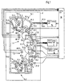
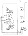
- Fig. 1 shows a printing unit 1 in accordance with the present invention.
- the printing unit 1 includes side walls 2 supporting upper and lower inking units 55.1, 55.2, blanket cylinders 4,6 and print cylinders 3,5.
- the upper inking unit 55.1 includes a fountain roller 50.1 and metering roller 51 which apply an ink film to distributor rollers 52, and to vibrator rollers 9, 10 and 11 for splitting the ink film and providing an even ink profile over the width of the printing unit.
- the vibrator rollers 10, 11 distribute the ink film to a group of upper form rollers 16.
- the upper form rollers 16 in turn, apply the ink film to a print form 70.1 mounted on the upper print cylinder 3.
- the vibrator rollers 13, 14 distribute the ink film to a group of lower form rollers 17, and the lower form rollers 17 apply the ink film to a print form 70.2 mounted on the lower print cylinder 5.
- the print form 70 may be constructed as a flat plate mounted by its respective ends to the print cylinder, as a sleeve-shaped print form mounted axially over the print cylinder, or in any other known manner.
- the print form 70 is suitable for receiving and transferring an image using water based inks.
- "waterless" type printing plates such as those manufactured by Toray Industries, are also suitable for printing with water based inks.
- a Toray Industries printing plate having an aluminum oxide substrate with an image area coated with a photopolymer whose surface is hydrophilic in nature and a non-image area coated with a silicone polymer may be used.
- An illustrative water-based ink for use with the present invention may include the components set forth below,
- the water phase of the ink is supplied by the water present in the acrylic resin latex, hydroxypropyl cellulose, hydroxyethyl ethylene urea, and the maleated rosin ester.
- the printing unit 1 is designed to maintain acceptable printing conditions for printing with water based inks through the use of one or more cooling units.
- a print cylinder cooling unit 7 is assigned to the upper and lower print cylinders 3, 5.
- the print cylinder cooling unit 7 includes a print cylinder inlet pipe 7.1 and a print cylinder outlet pipe 7.2 for each of the print cylinders 3, 5.
- a lower print cylinder sensor 19.2 is arranged near the lower print cylinder 5
- an upper print cylinder sensor 19.1 is arranged near the upper print cylinder 3.
- a pair of relative humidity sensors 60.1, 60.2 are mounted within the printing unit 1 to measure the relative humidity of the atmosphere in the upper print unit section 1.1 and lower printing unit section 1.2
- a pair of temperature sensors 60.3, 60.4 are mounted within the printing unit 1 to measure the temperature of the atmosphere in the upper print unit section 1.1 and lower printing unit section 1.2.
- a control unit 18 has respective inputs connected to the print cylinder sensors 19.1, 19.2, the relative humidity and temperature sensors 60.1, 60.2, 60.3, 60.4 and an output connected to the cooling unit 7.
- the control unit 18 periodically monitors the temperature of the print cylinders 3,5 via the sensors 19.1, 19.2, and of the atmosphere with the relative humidity sensors 60.1, 60.2 and temperature sensors 60.3, 60.4, and then controls the print cylinder cooling unit 7 as a function of the monitored temperature values.
- the print cylinder sensors 19.1, 19.2 can be constructed, for example, as infra-red sensors mounted adjacent to the print cylinders 3,5 to monitor the surface temperature of the print cylinders.
- the cooling unit 7 continuously circulates a cooling agent (e.g. water or air) through the print cylinders 3, 5 via the print cylinder inlet and outlet pipes 7.1, 7.2.
- a cooling agent e.g. water or air
- the temperature of the cylinders 3, 5 can be maintained at a predetermined level (e.g., at a setpoint or within a predetermined range).
- the predetermined level is preferably set slightly above the dew point of the atmosphere surrounding the ink carrying surfaces of the print cylinders in order to prevent condensation of water from the atmosphere onto the ink carrying surfaces, and to minimize evaporation of water from the water-based inks into the atmosphere.
- the predetermined level can be set as follows based upon the sensor readings.
- the upper and lower blanket cylinders 4, 6 have printing blankets 71.1, 71.2 mounted thereon for transferring an inked image from the print forms 70.1, 70.2 to a web of material 22 as shown in Fig. 3.
- the printing blanket 71 may be constructed as a flat blanket mounted by its respective ends to the blanket cylinder, as a gapless tubular printing blanket mounted axially over the blanket cylinder, or in any other known manner.
- a blanket cylinder cooling unit 8 is assigned to the upper and lower blanket cylinders 4, 6.
- the blanket cylinder cooling unit 8 includes a blanket cylinder inlet 8.1 and a blanket cylinder outlet 8.2 for each blanket cylinder.
- a lower blanket cylinder sensor 20.2 is arranged near the lower blanket cylinder 6, and an upper blanket cylinder sensor 20.1 is arranged near the upper blanket cylinder 4.
- the control unit 18 has respective inputs connected to the blanket cylinder sensors 20.1, 20.2 and an output connected to the cooling unit 8.
- the control unit 18 periodically monitors the temperature of the blanket cylinders 4,6 via the sensors 20.1, 20.2, and then controls the blanket cylinder cooling unit 8 as a function of the monitored temperature values as described above with regard to the print cylinders,
- the sensors 20 and cooling unit 8 can be constructed and controlled in the same manner as the sensors 19 and cooling unit 7.
- An inker cooling unit 15 is assigned to the upper vibrator rollers 9, 10, 11, the lower vibrator rollers 12, 13 and 14, and the upper and lower fountain rollers 50.1, 50.2 respectively.
- the cooling unit 15 includes an upper section 15.1 assigned to the upper inker 55.1 and a lower section 15.2 assigned to the lower inker 55.2.
- An inker inlet pipe 15.3 and outlet pipe 15.4 is connected to each roller 9-14, 50.1, 50.2.
- a respective inker sensor 21.1, 21.2 is assigned to each inking unit 55.1, 55.2. In the configuration of Fig. 1, sensor 21.1 senses the temperature at an outer ink carrying surface of roller 11, and sensor 21.2 senses the temperature at an outer ink carrying surface of roller 14.
- the control unit 18 has respective inputs connected to the inker sensors 21.1, 21.2 and an output connected to the inker cooling unit 15.
- the control unit 18 periodically monitors the temperature of the vibrator rollers 11, 14 via the sensors 20.1, 20.2, and then controls the inker cooling unit 15 as a function of the monitored temperature values as described above with regard to the print cylinders.
- the sensors 21 and cooling unit 15 can be constructed and controlled in the same manner as the sensors 19 and cooling unit 7.
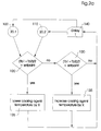
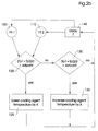
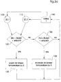
- Figures 2(a-c) show an illustrative flow chart for the control unit 18.
- the control unit monitors the surface temperature of the upper blanket (Tb 1 ) and of the lower blanket (Tb 2 ) via the sensors 20.1, 20.2. If an average of these sensor readings is above a set point, then the control unit 18 lowers the temperature of the cooling agent in the blanket cooling unit 8 by an amount X , waits a time period T, and then monitors the outputs of the sensors 20.1, 20.2 again. These steps are repeated until the average of the sensor readings is equal to the set point.
- the control unit 18 raises the temperature of the cooling agent in the blanket cooling unit 8 by an amount X , waits a time period T, monitors the outputs of the sensors 20.1, 20.2 again, and repeats these steps until the average of the sensor readings is equal to the set point
- the control unit monitors and controls the temperature of the print cylinders 3, 5 and inker rollers 9-14, 50.1, 50.2 in the same manner.
- the setpoint is set slightly above the dew point of the atmosphere surrounding the print cylinders, blanket cylinders, and inking unit.
- the relative humidity of the atmosphere surrounding the ink carrying surfaces of the inking unit, blanket cylinders. and print cylinders will be high enough to prevent any significant evaporation of water from the ink, but low enough to prevent condensation of water from the atmosphere onto the ink carrying surfaces.
- the set point can be obtained based upon the monitored values of the sensors 60.1 through 60.4 as described above.
- the cooling units 7, 8, and 15 need not include means for heating the cooling agent.
- the above referenced flow charts are merely illustrative, and could be replaced with any suitable algorithm known in the art for matching a measured value to a desired value.
- a single temperature sensor (60.3 or 60.4) and humidity sensor (60.1 or 60.2) could be used.
- the temperature of the cooling agent circulated within both print cylinders will be a function of the temperature measured at the ink carrying surface of only one of the cylinders (3 or 5).
- the sensor pairs 20.1, 20.2 and 21.1, 21.2 could likewise be replaced with single sensors measuring the temperature at one of the blanket cylinders (4 or 6) and at one of the inking units (55.1 or 55.2).
- the temperature of the ink and of the surfaces the ink is applied to should be maintained at certain predetermined levels. For example, in a water based ink containing 2% ethanol amine or ammonia, if the temperature of the print cylinders is maintained between 33-35 [93-95 degrees] and 75 -95 % humidity, high print quality can be maintained. Naturally, these levels are merely illustrative, and may vary in accordance with a number of factors including the particular construction of the printing unit, the particular composition of the water based ink, and the paper being used.
- the temperature of the cylinders 3-6 and rollers 9-14 are monitored by the control unit, and is maintained within the desired temperature range (or at a desired set point) by selectively controlling the temperature of the cooling agent flowing through these cylinders and rollers.
- the control unit 18 when a printing press is first started, the printing unit components 3-6, 9-14, 50.1, 50.2 will be relatively cold. Therefore, the control unit 18, by monitoring the temperature sensors 19-21, will determine that the temperature on the ink carrying surfaces of the blanket cylinders 4, 6, print cylinders 3,5, and vibrator rollers 11, 14 is below the desired temperature level for the water based ink and paper being used. The control unit 18 will then advise the press operator to pre-heat the printing unit 1 prior to printing. Such a preheating could be accomplished by running the press while off impression until the temperature of the blanket cylinders 4, 6, print cylinders 3,5, and vibrator rollers 11, 14 has reached the desired level.
- control unit 18 could raise the temperature of the cooling agent in the blanket cylinder cooling unit 8, the print cylinder cooling unit 7, and the inker cooling unit 15 until the temperature of the blanket cylinders 4, 6, print cylinders 3,5, and vibrator rollers 11, 14 has reached the desired level.
- the temperature on the ink carrying surfaces of one or more of the blankets, print forms or rollers (70, 71, 9-14, 50.1, 50.2) within the printing unit 1 may rise above the desired temperature level.
- the control unit 18, by monitoring the temperature sensors 19-21, will detect that the temperature on the ink carrying surfaces of the blankets, print forms , and/or vibrator rollers (71.1, 71.2, 70.1, 70.2, 11, and/or 14) is above the desired temperature level for the water based ink and paper being used, and will then lower the temperature of the cooling agent in the respective cooling units (7,8, and/or 15) as necessary until the temperature of the blankets, print forms, and/or vibrator rollers has reached the desired level.
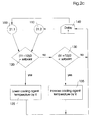
- Fig. 3 shows a further embodiment of the printing unit of Fig. 1.
- the pipes 7.1, 7.2, 8.1, 8.2, 15.3, 15.4 and sensors 19-21 have been omitted for ease of illustration.
- blowing sections 23.1, 23.2 are mounted within the printing unit 1, and connected to a blowing unit 23 via an air inlet pipe 24.1 and an air exhaust pipe 24.2.
- the blowing unit 23 includes an air cooling mechanism and an air heating mechanism, and is coupled to and controlled by the control unit 18 to maintain the temperature of the water based ink carrying surfaces of the blanket cylinders 4, 6 at the set point.
- the blowing devices 23.1 and 23.2 each include outputs 80 to blow air onto the surfaces of the blanket cylinder 4, 6 carrying the water based ink films.
- the blowing devices 23.1 and 23.2 also include suction inputs 81 for sucking the atmosphere surrounding the water based ink carrying surfaces out through the air exhaust pipe 24.2. In this manner, the water based ink carrying surfaces of the blanket are cooled or heated from the outside via the blowing unit 23, and from the inside via the cooling units 8.
- the control unit 18 monitors the surface temperature of the upper blanket cylinder (Tb 1 ) and of the lower blanket cylinder (Tb 2 ) via the sensors 20.1, 20.2. If an average of these sensor readings is above the set point, then the control unit 18 lowers the temperature of the air output from the air inlet 24.1 by an amount X , waits a time period T, and then monitors the outputs of the sensors 20.1, 20.2 again. These steps are repeated until the average of the sensor readings is equal to the set point.
- the control unit 18 raises the temperature of the air output from the air inlet 24.1 by an amount X , waits a time period T, monitors the outputs of the sensors 20.1, 20.2 again, and repeats these steps until the average of the sensor readings is equal to the set point
- the heating and/or cooling of the air by the blowing device 23 can be accomplished inside or outside the blowing devices 23.1, 23.2.
- the blowing devices 23.1, 23.2 could be arranged within the printing unit 1 to blow air on both the print cylinders 3,5 and the blanket cylinders 4,6.
- the air heating mechanism can be omitted from the blowing device 23.
- the above referenced flow chart is merely illustrative, and could be replaced with any suitable algorithm known in the art for marching a measured value to a desired value.
- the blowing unit 23 includes a humidifier 255 which is controlled by the control unit 18 and supplied by water supply lines 250.1, 250.2.
- the humidifier 255 may be arranged within the blowing unit 23, within the blowing devices 23.1, 23.2, in between the blowing unit 23 and blowing devices 23.1, 23.2, or in any other suitable location. If the control unit 18 determines that the monitored relative humidity is below a humidity set point, it will activate the humidifier until the monitored humidity is equal to the humidity set point.
- the humidity set point e.g. between 75% and 95% relative humidity
- the temperature set point can be set at a static value (e.g., 33-35°C [93-95 degrees Fahrenheit]).
- Fig. 4 shows a temperature controlling device in accordance with the present invention for maintaining an even temperature profile across the printing unit 1.
- the sidewalls 2 include a gear-side wall 2.1 and a work-side wall 2.2.
- the gear-side wall 2.1 which houses the gears which drive the cylinders and/or rollers in the printing unit 1, tends to become significantly hotter than the work-side wall 2.2. Consequently, it is advantageous to cool the gear-side wall 2.1 to provide an even temperature profile over the width of said printing unit 1.
- a gear-side temperature sensor 26 is mounted on the gear-side wall 2.1 and a work-side temperature sensor 28 is mounted on the work-side wall 2.2.
- Each of the temperature sensors 26, 28 is connected to the control unit 18.
- a friction reducing fluid such as mineral oil or synthetic oil is conventionally provided within a gear box 32 of the gear-side wall 2.1 to lubricate the moving parts within the gear-side wall 2.1.
- a fluid distribution 82 is provided for circulating the friction reducing fluid to and from a heat exchanger 29.
- the heat exchanger 29 may be of conventional construction, and operates to cool the fluid in the fluid distribution 82 by, for example, inter-twining the fluid distribution 82 with a fluid pipe 62 containing a cooling fluid such as water.
- the control unit 18 monitors the temperature of the work-side and gear-side walls 2.2, 2.1 via the sensors and controls a fluid cooling unit 61 as a function of the monitored temperatures.
- ⁇ 7°C [7 degrees Fahrenheit] ).
- the design of the work-side frame components is such that the temperature of the work-side frame at 27 does remains within approximately 10 degrees Farenheit of the ambient temperature of the surrounding atmosphere. If, however, the work-side frame exceeds the ambient temperature by more than 10 degrees Farenheit, it may be necessary to provide a work-side cooling mechanism for the work side frame 2.2.
- the cooling mechanism could, for example, include a cooling unit 99 which circulates a cooling agent through pipes 98 which are mounted to the work-side frame 2.2.
- the cooling unit 99 could monitor the ambient temperature of the air surrounding the work-side frame 2.2 via a temperature sensor 27, monitor the temperature of the work-side frame 2.2 via the sensor 28, and lower the temperature of the cooling agent if the difference between the monitored values exceed 10°C [10 degrees Farenheit].
- Fig. 5 shows a longitudinal section of one of the blanket cylinders 4, 6.
- the blanket cylinder 4, 6 includes the blanket cylinder inlet 8.1 and a blanket cylinder outlet 8.2 for circulating the cooling agent through the blanket cylinder.
- the blanket cylinder includes a compressed air inlet 36 which transmits compressed air across the length of the cylinder and out a plurality of apparatus 38 along the surface of the blanket cylinder in order to axially install and remove a printing blanket.
- the air inlet 36 is isolated from the cooling agent circulating within the cylinder 33.
- the cooling agent can be circulated through the print cylinder 3, 5, and rollers 9 - 14 in a similar manner.
Landscapes
- Engineering & Computer Science (AREA)
- Mechanical Engineering (AREA)
- Inking, Control Or Cleaning Of Printing Machines (AREA)
- Printing Methods (AREA)
- Supply, Installation And Extraction Of Printed Sheets Or Plates (AREA)
Applications Claiming Priority (3)
| Application Number | Priority Date | Filing Date | Title |
|---|---|---|---|
| US08/615,351 US5694848A (en) | 1996-03-13 | 1996-03-13 | Printing unit for water based inks |
| PCT/EP1997/000907 WO1997033750A1 (en) | 1996-03-13 | 1997-02-26 | Printing unit for water-based inks |
| US615351 | 2000-07-12 |
Publications (2)
| Publication Number | Publication Date |
|---|---|
| EP0886577A1 EP0886577A1 (en) | 1998-12-30 |
| EP0886577B1 true EP0886577B1 (en) | 1999-12-01 |
Family
ID=24464988
Family Applications (1)
| Application Number | Title | Priority Date | Filing Date |
|---|---|---|---|
| EP97905086A Expired - Lifetime EP0886577B1 (en) | 1996-03-13 | 1997-02-26 | Printing unit for water-based inks |
Country Status (8)
Cited By (8)
| Publication number | Priority date | Publication date | Assignee | Title |
|---|---|---|---|---|
| WO2004054805A1 (de) | 2002-12-17 | 2004-07-01 | Koenig & Bauer Aktiengesellschaft | Verfahren zur temperierung, regeleinrichtung sowie vorrichtung zur temperierung |
| EP1435290A1 (de) | 2002-12-17 | 2004-07-07 | Koenig & Bauer Aktiengesellschaft | Verwirbelungsstrecke und Vorrichtung zur Temperierung eines Bauteiles |
| DE102008001309A1 (de) | 2008-02-11 | 2009-08-13 | Koenig & Bauer Aktiengesellschaft | Verfahren und Vorrichtung zum Steuern einer Druckmaschine |
| DE102009001598A1 (de) | 2009-03-17 | 2010-09-30 | Koenig & Bauer Aktiengesellschaft | Vorrichtung zur Temperierung von Bauteilen einer Druckeinheit |
| DE102009001597A1 (de) | 2009-03-17 | 2010-09-30 | Koenig & Bauer Aktiengesellschaft | Vorrichtung zur Temperierung mindestens eines Bauteils einer Druckeinheit |
| DE102009001596A1 (de) | 2009-03-17 | 2010-09-30 | Koenig & Bauer Aktiengesellschaft | Vorrichtung zur Temperierung mindestens eines Bauteils einer Druckeinheit und eine Vorrichtung zur Temperierung von Bauteilen einer mehrere übereinander angeordnete Druckwerke aufweisenden Druckeinheit |
| DE102011076334A1 (de) | 2011-05-24 | 2012-11-29 | Koenig & Bauer Aktiengesellschaft | Vorrichtung und Verfahren zur Überwachung und/oder Regelung einer Temperierung von Bauteilen einer Druckmaschine |
| US8327762B2 (en) | 2009-03-17 | 2012-12-11 | Koenig & Bauer Aktiengsellschaft | Printing presses having one or more printing units embodied as printing towers for double-sided multicolor printing, and devices for controlling the temperature of components of one or more of the printing units |
Families Citing this family (39)
| Publication number | Priority date | Publication date | Assignee | Title |
|---|---|---|---|---|
| US5972088A (en) * | 1996-03-13 | 1999-10-26 | Sun Chemical Corporation | Water-based gravure printing ink |
| US6200372B1 (en) | 1996-03-13 | 2001-03-13 | Sun Chemical Corporation | Water-based offset lithographic newspaper printing ink |
| US6209456B1 (en) * | 1996-03-13 | 2001-04-03 | Heidelberger Druckmaschinen Ag | Web- and sheet-fed printing unit using various ink types, particularly water-based inks |
| DE19750960C2 (de) * | 1996-11-26 | 2002-08-14 | Roland Man Druckmasch | Filmfarbwerk für eine Rotationsdruckmaschine |
| DE59801628D1 (de) | 1997-01-27 | 2001-11-08 | Oce Printing Systems Gmbh | Verfahren und einrichtung zum bedrucken eines trägermaterials unter verwendung einer strukturierten eisschicht |
| JPH10235830A (ja) * | 1997-03-01 | 1998-09-08 | Heidelberger Druckmas Ag | 輪転印刷機の中央潤滑装置 |
| DE19717524C2 (de) * | 1997-04-25 | 2002-04-04 | Roland Man Druckmasch | Farbwerk für eine Druckmaschine |
| JP3403035B2 (ja) | 1997-11-07 | 2003-05-06 | 三菱重工業株式会社 | 印刷機の温度制御装置 |
| CA2297045A1 (en) * | 1997-11-26 | 1999-06-03 | Sun Chemical Corporation | Water-based offset lithographic newspaper printing ink |
| DE19812149A1 (de) * | 1998-03-20 | 1999-09-23 | Heidelberger Druckmasch Ag | Kühlwalze |
| DE19904891C1 (de) * | 1999-02-06 | 2000-08-31 | Voith Sulzer Papiertech Patent | Kalander |
| US6444022B1 (en) | 2000-05-20 | 2002-09-03 | Sun Chemical Corporation | Water based offset lithographic printing ink |
| DE10137166A1 (de) | 2000-08-23 | 2002-03-07 | Heidelberger Druckmasch Ag | Verfahren zur Temperierung von Druckformoberflächen während des Druckes |
| DE10115435B8 (de) * | 2001-03-29 | 2007-02-08 | Maschinenfabrik Wifag | Verfahren zur Erzeugung eines Druckbilds und/oder zur Löschung eines Druckbilds einer Nassoffset-Druckform mit fotothermisch veränderbarem Material |
| JP4412447B2 (ja) * | 2001-05-29 | 2010-02-10 | 東洋製罐株式会社 | 印刷機の温度調節方法及びその装置 |
| FR2826314B1 (fr) * | 2001-06-22 | 2003-12-12 | Sparflex | Procede et dispositif d'impression offset |
| US6851359B2 (en) * | 2001-06-22 | 2005-02-08 | Sparflex | Offset printing method and device |
| US6862989B2 (en) * | 2001-09-19 | 2005-03-08 | Goss International Americas, Inc. | Blanket cylinder with integrated compressible layer |
| DE10157271B4 (de) * | 2001-11-22 | 2005-02-03 | Koenig & Bauer Ag | Verfahren und Vorrichtung zur Regelung einer Temperatur eines Formzylinders |
| JP2005510384A (ja) * | 2001-11-22 | 2005-04-21 | ケーニツヒ ウント バウエル アクチエンゲゼルシヤフト | 印刷装置におけるインキの使用法および輪転印刷機の印刷装置 |
| DE10219443A1 (de) * | 2002-05-02 | 2003-11-20 | Roland Man Druckmasch | Verfahren und Vorrichtung zum Betrieb einer Temperiereinrichtung |
| US6709503B1 (en) | 2002-12-19 | 2004-03-23 | Sun Chemical Corporation | Waterbased heatset offset ink compositions |
| US6829991B1 (en) * | 2003-10-29 | 2004-12-14 | Goss International Americas, Inc. | Inker driven shaftless unit |
| EP1727676B1 (de) * | 2004-03-23 | 2014-01-22 | Koenig & Bauer Aktiengesellschaft | Druckmaschinen mit mindestens einem mit einem stellglied einstellbaren maschinenelement |
| JP5005907B2 (ja) * | 2004-11-11 | 2012-08-22 | ハイデルベルガー ドルツクマシーネン アクチエンゲゼルシヤフト | 印刷機 |
| CN1939721B (zh) * | 2005-09-27 | 2010-12-15 | 海德堡印刷机械股份公司 | 用于对印刷机调节温度的方法 |
| JP2007098616A (ja) * | 2005-09-30 | 2007-04-19 | Mitsubishi Heavy Ind Ltd | 印刷機械 |
| DE102006055696A1 (de) * | 2006-11-23 | 2008-05-29 | Contemp Druckereitechnik Gmbh | Verfahren und Vorrichtung zur unabhängigen Temperierung von Farbwerken und/oder Zonen von Farbwerken einer Offsetdruckmaschine |
| WO2010058842A1 (ja) * | 2008-11-21 | 2010-05-27 | 三菱重工業株式会社 | 印刷機 |
| DE102009000511B4 (de) * | 2009-01-30 | 2011-02-24 | Koenig & Bauer Aktiengesellschaft | Reinigungsanlage |
| US20120103221A1 (en) * | 2010-10-29 | 2012-05-03 | Palo Alto Research Center Incorporated | Cleaning Method for a Variable Data Lithography System |
| US20120103213A1 (en) * | 2010-10-29 | 2012-05-03 | Palo Alto Research Center Incorporated | Ink Rheology Control Subsystem for a Variable Data Lithography System |
| US20120103218A1 (en) * | 2010-10-29 | 2012-05-03 | Palo Alto Research Center Incorporated | Method of Ink Rheology Control in a Variable Data Lithography System |
| US20120103214A1 (en) * | 2010-10-29 | 2012-05-03 | Palo Alto Research Center Incorporated | Heated Inking Roller for a Variable Data Lithography System |
| JP6396094B2 (ja) * | 2014-06-26 | 2018-09-26 | 大和グランド株式会社 | 印刷機及びインキの温度調整方法 |
| JP2016083791A (ja) * | 2014-10-23 | 2016-05-19 | Dicグラフィックス株式会社 | 水性インキ組成物および水性ワニス組成物を用いた印刷方法及びその方法によって得られる印刷物 |
| DE102015202183A1 (de) * | 2015-02-06 | 2016-08-11 | Koenig & Bauer Ag | Temperieraggregat zur Temperierung von Funktionsteilen einer Druckmaschine sowie Druckanlage mit einer Druckmaschine und einem Temperieraggregat |
| DE102018217261A1 (de) * | 2017-11-09 | 2019-05-09 | Heidelberger Druckmaschinen Aktiengesellschaft | Druckverfahren und Bogendruckmaschine |
| JP6733777B1 (ja) * | 2019-05-13 | 2020-08-05 | 東洋製罐株式会社 | 印刷機及び印刷機の状態監視方法 |
Family Cites Families (29)
| Publication number | Priority date | Publication date | Assignee | Title |
|---|---|---|---|---|
| US2260364A (en) * | 1940-05-18 | 1941-10-28 | John Waldron Corp | Ink distribution system |
| US2972298A (en) * | 1954-06-04 | 1961-02-21 | Method of viscosity control in printing | |
| US2972302A (en) * | 1955-11-25 | 1961-02-21 | Interchem Corp | Method of typographic printing |
| US3031961A (en) * | 1959-01-02 | 1962-05-01 | Interchem Corp | Method of typographic printing |
| US3141408A (en) * | 1961-11-21 | 1964-07-21 | Interchem Corp | High speed printing with super-fast inks |
| US3356030A (en) * | 1964-04-30 | 1967-12-05 | Interchem Corp | Planographic printing method |
| US3741115A (en) * | 1967-08-21 | 1973-06-26 | L Keller | Method of and apparatus for controlling lithographic printing |
| DE1611233A1 (de) * | 1967-08-21 | 1970-12-10 | Dipl Rer Pol Leo Keller | Steuerung der Temperaturverhaeltnisse in Feucht- und Farbwerk von Offsetdruckmaschinen |
| US3877372A (en) * | 1973-12-03 | 1975-04-15 | Kenneth W Leeds | Treatment of a printing plate with a dampening liquid |
| US4173554A (en) * | 1978-07-10 | 1979-11-06 | Sun Chemical Corporation | Aqueous printing inks with improved transfer properties |
| US4278467A (en) * | 1978-09-11 | 1981-07-14 | Graphic Arts Technical Foundation | Substitutive additives for isopropyl alcohol in fountain solution for lithographic offset printing |
| JPS5862053A (ja) * | 1981-10-08 | 1983-04-13 | 株式会社 篠原鉄工所 | オフセツト印刷機 |
| US5026755A (en) * | 1985-03-13 | 1991-06-25 | Sun Chemical Corporation | Water-based printing ink prepared from polyamide/acrylic graft copolymers |
| JPS62191152A (ja) * | 1986-02-18 | 1987-08-21 | Mitsubishi Heavy Ind Ltd | 水無し平版印刷機 |
| US4854969A (en) * | 1986-07-02 | 1989-08-08 | Sun Chemical Corporation | Lithographic fountain solutions |
| US4954556A (en) * | 1987-11-23 | 1990-09-04 | Ppg Industries, Inc. | Water-based ink compositions |
| DE3814049A1 (de) * | 1988-04-26 | 1989-11-09 | Koenig & Bauer Ag | Verfahren und einrichtung fuer den flexo-druck |
| US4920881A (en) * | 1988-05-02 | 1990-05-01 | Webquip Corporation | Method of cooling hot webs |
| JPH01321453A (ja) * | 1988-06-23 | 1989-12-27 | Canon Inc | 電子写真装置 |
| JP2773824B2 (ja) * | 1989-09-18 | 1998-07-09 | 株式会社小森コーポレーション | インキローラ温度制御装置 |
| US5098478A (en) * | 1990-12-07 | 1992-03-24 | Sun Chemical Corporation | Water-based ink compositions |
| IT1248446B (it) * | 1990-12-19 | 1995-01-19 | Componenti Grafici Srl | Rullo pressore per macchina da stampa, con sistema di condizionamento e di lubrificazione ad olio |
| DE4202544A1 (de) * | 1992-01-30 | 1993-08-05 | Baldwin Gegenheimer Gmbh | Druckplatten-temperierungssystem fuer eine druckmaschine |
| DE4231263A1 (de) * | 1992-09-18 | 1994-03-24 | Heidelberger Druckmasch Ag | Druckwerksvorrichtung einer Rollendruckmaschine mit Abschmierverhinderungseinrichtung |
| DE4326835A1 (de) * | 1993-08-10 | 1995-02-16 | Baldwin Gegenheimer Gmbh | Temperierungssystem für Druckmaschinenzylinder |
| US5370906A (en) * | 1993-11-02 | 1994-12-06 | Dankert; Fred | Waterless planographic plates |
| US5417749A (en) * | 1994-03-29 | 1995-05-23 | Sun Chemical Corporation | Microemulsion printing ink |
| US5471927A (en) * | 1994-05-26 | 1995-12-05 | Royse Manufacturing Company, Inc. | Temperature controlled printing press |
| US5465661A (en) * | 1994-10-11 | 1995-11-14 | R. R. Donnelley & Sons Company | Printing press temperature adjustment system |
-
1996
- 1996-03-13 US US08/615,351 patent/US5694848A/en not_active Expired - Lifetime
-
1997
- 1997-02-26 WO PCT/EP1997/000907 patent/WO1997033750A1/en active IP Right Grant
- 1997-02-26 CN CN97192666A patent/CN1094093C/zh not_active Expired - Fee Related
- 1997-02-26 EP EP97905086A patent/EP0886577B1/en not_active Expired - Lifetime
- 1997-02-26 JP JP53222997A patent/JP4021488B2/ja not_active Expired - Fee Related
- 1997-02-26 DE DE69700879T patent/DE69700879T2/de not_active Expired - Lifetime
- 1997-02-26 CA CA002242892A patent/CA2242892C/en not_active Expired - Fee Related
- 1997-02-26 AU AU18768/97A patent/AU1876897A/en not_active Abandoned
Cited By (20)
| Publication number | Priority date | Publication date | Assignee | Title |
|---|---|---|---|---|
| WO2004054805A1 (de) | 2002-12-17 | 2004-07-01 | Koenig & Bauer Aktiengesellschaft | Verfahren zur temperierung, regeleinrichtung sowie vorrichtung zur temperierung |
| EP1435290A1 (de) | 2002-12-17 | 2004-07-07 | Koenig & Bauer Aktiengesellschaft | Verwirbelungsstrecke und Vorrichtung zur Temperierung eines Bauteiles |
| DE10328234B4 (de) * | 2002-12-17 | 2005-09-15 | Koenig & Bauer Ag | Verfahren zur Temperierung sowie Vorrichtung zur Temperierung |
| DE10328235B4 (de) * | 2002-12-17 | 2005-10-06 | Koenig & Bauer Ag | Verwirbelungsstrecke und Vorrichtung zur Temperierung eines Bauteils |
| CN100368191C (zh) * | 2002-12-17 | 2008-02-13 | 柯尼格及包尔公开股份有限公司 | 恒温的方法和用于恒温的调节装置 |
| US7740185B2 (en) | 2002-12-17 | 2010-06-22 | Koenig & Bauer Aktiengesellschaft | Tempering method, control device and tempering device |
| DE102008001309A1 (de) | 2008-02-11 | 2009-08-13 | Koenig & Bauer Aktiengesellschaft | Verfahren und Vorrichtung zum Steuern einer Druckmaschine |
| WO2009100783A2 (de) | 2008-02-11 | 2009-08-20 | Koenig & Bauer Aktiengesellschaft | Verfahren und vorrichtung zum steuern einer druckmaschine |
| DE102008001309B4 (de) * | 2008-02-11 | 2013-05-02 | Koenig & Bauer Aktiengesellschaft | Verfahren und Vorrichtung zum Steuern einer Druckmaschine |
| US8127672B2 (en) | 2008-02-11 | 2012-03-06 | Koenig & Bauer Aktiengesellschaft | Method and device for controlling at least one rotating component of a printing press |
| DE102009001596A1 (de) | 2009-03-17 | 2010-09-30 | Koenig & Bauer Aktiengesellschaft | Vorrichtung zur Temperierung mindestens eines Bauteils einer Druckeinheit und eine Vorrichtung zur Temperierung von Bauteilen einer mehrere übereinander angeordnete Druckwerke aufweisenden Druckeinheit |
| DE102009001597B4 (de) * | 2009-03-17 | 2011-11-10 | Koenig & Bauer Aktiengesellschaft | Vorrichtung zur Temperierung von Bauteilen einer oder mehrerer Druckeinheiten für den beidseitigen mehrfarbigen Druck |
| DE102009001596B4 (de) * | 2009-03-17 | 2011-12-15 | Koenig & Bauer Aktiengesellschaft | Vorrichtung zur Temperierung von Bauteilen einer mehrere übereinander angeordnete Trockenoffsetdruckwerke aufweisenden Druckeinheit |
| DE102009001597A1 (de) | 2009-03-17 | 2010-09-30 | Koenig & Bauer Aktiengesellschaft | Vorrichtung zur Temperierung mindestens eines Bauteils einer Druckeinheit |
| US8327762B2 (en) | 2009-03-17 | 2012-12-11 | Koenig & Bauer Aktiengsellschaft | Printing presses having one or more printing units embodied as printing towers for double-sided multicolor printing, and devices for controlling the temperature of components of one or more of the printing units |
| DE102009001598B4 (de) * | 2009-03-17 | 2013-02-07 | Koenig & Bauer Aktiengesellschaft | Vorrichtung zur Temperierung von Bauteilen einer Druckeinheit |
| DE102009001598A1 (de) | 2009-03-17 | 2010-09-30 | Koenig & Bauer Aktiengesellschaft | Vorrichtung zur Temperierung von Bauteilen einer Druckeinheit |
| EP2639065A1 (de) | 2009-03-17 | 2013-09-18 | Koenig & Bauer Aktiengesellschaft | Druckmaschine mit einer oder mehreren als Drucktürme ausgebildeten Druckeinheiten für den beidseitigen mehrfarbigen Druck und einer Vorrichtung zur Temperierung von Bauteilen einer oder mehrerer der Druckeinheiten |
| DE102011076334A1 (de) | 2011-05-24 | 2012-11-29 | Koenig & Bauer Aktiengesellschaft | Vorrichtung und Verfahren zur Überwachung und/oder Regelung einer Temperierung von Bauteilen einer Druckmaschine |
| DE102011076334B4 (de) * | 2011-05-24 | 2015-12-17 | Koenig & Bauer Ag | Verfahren und Vorrichtungen zur Überwachung einer Temperierung von Bauteilen einer Druckmaschine |
Also Published As
| Publication number | Publication date |
|---|---|
| WO1997033750A1 (en) | 1997-09-18 |
| CA2242892C (en) | 2003-12-23 |
| CN1094093C (zh) | 2002-11-13 |
| CA2242892A1 (en) | 1997-09-18 |
| JP2000506091A (ja) | 2000-05-23 |
| JP4021488B2 (ja) | 2007-12-12 |
| EP0886577A1 (en) | 1998-12-30 |
| DE69700879D1 (de) | 2000-01-05 |
| DE69700879T2 (de) | 2000-06-21 |
| CN1212653A (zh) | 1999-03-31 |
| AU1876897A (en) | 1997-10-01 |
| US5694848A (en) | 1997-12-09 |
Similar Documents
| Publication | Publication Date | Title |
|---|---|---|
| EP0886577B1 (en) | Printing unit for water-based inks | |
| US8272324B2 (en) | Systems for tempering components of a printing machine | |
| EP0886578B1 (en) | Printing unit using various ink types | |
| JP4593921B2 (ja) | 印刷装置を運転する方法およびインキの使用法 | |
| US6209456B1 (en) | Web- and sheet-fed printing unit using various ink types, particularly water-based inks | |
| US8166877B2 (en) | Printing press having a dryer device for varnished sheets | |
| US20070068409A1 (en) | Method for controlling a temperature of a press and press having a temperature control device | |
| EP0697290A1 (en) | Multiple color offset press utilizing aqueous ink and waterless printing plates with interstation drying and extraction | |
| CA2676814C (en) | Web coating applicator with cooling and material recovery | |
| JP2003311925A (ja) | 乾燥ステーションを備えた印刷機 | |
| DE102006056315A1 (de) | Kurzfarbwerk für Offset-Rotationsdruckmaschinen | |
| JPH07171944A (ja) | 補刷印刷ユニットを有するウエブ式輪転印刷機 |
Legal Events
| Date | Code | Title | Description |
|---|---|---|---|
| PUAI | Public reference made under article 153(3) epc to a published international application that has entered the european phase |
Free format text: ORIGINAL CODE: 0009012 |
|
| 17P | Request for examination filed |
Effective date: 19980812 |
|
| AK | Designated contracting states |
Kind code of ref document: A1 Designated state(s): CH DE FR GB IT LI NL SE |
|
| GRAG | Despatch of communication of intention to grant |
Free format text: ORIGINAL CODE: EPIDOS AGRA |
|
| GRAG | Despatch of communication of intention to grant |
Free format text: ORIGINAL CODE: EPIDOS AGRA |
|
| GRAH | Despatch of communication of intention to grant a patent |
Free format text: ORIGINAL CODE: EPIDOS IGRA |
|
| 17Q | First examination report despatched |
Effective date: 19990507 |
|
| GRAH | Despatch of communication of intention to grant a patent |
Free format text: ORIGINAL CODE: EPIDOS IGRA |
|
| GRAA | (expected) grant |
Free format text: ORIGINAL CODE: 0009210 |
|
| AK | Designated contracting states |
Kind code of ref document: B1 Designated state(s): CH DE FR GB IT LI NL SE |
|
| REG | Reference to a national code |
Ref country code: CH Ref legal event code: EP |
|
| REF | Corresponds to: |
Ref document number: 69700879 Country of ref document: DE Date of ref document: 20000105 |
|
| ITF | It: translation for a ep patent filed | ||
| PG25 | Lapsed in a contracting state [announced via postgrant information from national office to epo] |
Ref country code: SE Free format text: LAPSE BECAUSE OF NON-PAYMENT OF DUE FEES Effective date: 20000227 |
|
| ET | Fr: translation filed | ||
| PLBE | No opposition filed within time limit |
Free format text: ORIGINAL CODE: 0009261 |
|
| STAA | Information on the status of an ep patent application or granted ep patent |
Free format text: STATUS: NO OPPOSITION FILED WITHIN TIME LIMIT |
|
| EUG | Se: european patent has lapsed |
Ref document number: 97905086.1 |
|
| 26N | No opposition filed | ||
| PG25 | Lapsed in a contracting state [announced via postgrant information from national office to epo] |
Ref country code: NL Free format text: LAPSE BECAUSE OF NON-PAYMENT OF DUE FEES Effective date: 20010901 |
|
| NLV4 | Nl: lapsed or anulled due to non-payment of the annual fee |
Effective date: 20010901 |
|
| REG | Reference to a national code |
Ref country code: GB Ref legal event code: IF02 |
|
| REG | Reference to a national code |
Ref country code: GB Ref legal event code: 732E |
|
| PG25 | Lapsed in a contracting state [announced via postgrant information from national office to epo] |
Ref country code: IT Free format text: LAPSE BECAUSE OF NON-PAYMENT OF DUE FEES Effective date: 20050226 |
|
| REG | Reference to a national code |
Ref country code: FR Ref legal event code: TP |
|
| PGFP | Annual fee paid to national office [announced via postgrant information from national office to epo] |
Ref country code: FR Payment date: 20110309 Year of fee payment: 15 Ref country code: DE Payment date: 20110225 Year of fee payment: 15 Ref country code: CH Payment date: 20110223 Year of fee payment: 15 |
|
| PGFP | Annual fee paid to national office [announced via postgrant information from national office to epo] |
Ref country code: GB Payment date: 20110223 Year of fee payment: 15 |
|
| REG | Reference to a national code |
Ref country code: CH Ref legal event code: PL |
|
| GBPC | Gb: european patent ceased through non-payment of renewal fee |
Effective date: 20120226 |
|
| PG25 | Lapsed in a contracting state [announced via postgrant information from national office to epo] |
Ref country code: LI Free format text: LAPSE BECAUSE OF NON-PAYMENT OF DUE FEES Effective date: 20120229 Ref country code: CH Free format text: LAPSE BECAUSE OF NON-PAYMENT OF DUE FEES Effective date: 20120229 |
|
| REG | Reference to a national code |
Ref country code: FR Ref legal event code: ST Effective date: 20121031 |
|
| REG | Reference to a national code |
Ref country code: DE Ref legal event code: R119 Ref document number: 69700879 Country of ref document: DE Effective date: 20120901 |
|
| PG25 | Lapsed in a contracting state [announced via postgrant information from national office to epo] |
Ref country code: FR Free format text: LAPSE BECAUSE OF NON-PAYMENT OF DUE FEES Effective date: 20120229 Ref country code: GB Free format text: LAPSE BECAUSE OF NON-PAYMENT OF DUE FEES Effective date: 20120226 |
|
| PG25 | Lapsed in a contracting state [announced via postgrant information from national office to epo] |
Ref country code: DE Free format text: LAPSE BECAUSE OF NON-PAYMENT OF DUE FEES Effective date: 20120901 |