EP0867608B1 - Lufteinlasssystem für eine Viertaktbrennkraftmaschine - Google Patents
Lufteinlasssystem für eine Viertaktbrennkraftmaschine Download PDFInfo
- Publication number
- EP0867608B1 EP0867608B1 EP98105656A EP98105656A EP0867608B1 EP 0867608 B1 EP0867608 B1 EP 0867608B1 EP 98105656 A EP98105656 A EP 98105656A EP 98105656 A EP98105656 A EP 98105656A EP 0867608 B1 EP0867608 B1 EP 0867608B1
- Authority
- EP
- European Patent Office
- Prior art keywords
- air intake
- throttle
- valve
- foregoing
- fuel
- Prior art date
- Legal status (The legal status is an assumption and is not a legal conclusion. Google has not performed a legal analysis and makes no representation as to the accuracy of the status listed.)
- Expired - Lifetime
Links
Images


Classifications
-
- F—MECHANICAL ENGINEERING; LIGHTING; HEATING; WEAPONS; BLASTING
- F02—COMBUSTION ENGINES; HOT-GAS OR COMBUSTION-PRODUCT ENGINE PLANTS
- F02M—SUPPLYING COMBUSTION ENGINES IN GENERAL WITH COMBUSTIBLE MIXTURES OR CONSTITUENTS THEREOF
- F02M35/00—Combustion-air cleaners, air intakes, intake silencers, or induction systems specially adapted for, or arranged on, internal-combustion engines
- F02M35/10—Air intakes; Induction systems
- F02M35/104—Intake manifolds
- F02M35/112—Intake manifolds for engines with cylinders all in one line
-
- F—MECHANICAL ENGINEERING; LIGHTING; HEATING; WEAPONS; BLASTING
- F02—COMBUSTION ENGINES; HOT-GAS OR COMBUSTION-PRODUCT ENGINE PLANTS
- F02B—INTERNAL-COMBUSTION PISTON ENGINES; COMBUSTION ENGINES IN GENERAL
- F02B31/00—Modifying induction systems for imparting a rotation to the charge in the cylinder
- F02B31/04—Modifying induction systems for imparting a rotation to the charge in the cylinder by means within the induction channel, e.g. deflectors
- F02B31/06—Movable means, e.g. butterfly valves
- F02B31/08—Movable means, e.g. butterfly valves having multiple air inlets, i.e. having main and auxiliary intake passages
- F02B31/087—Movable means, e.g. butterfly valves having multiple air inlets, i.e. having main and auxiliary intake passages having three or more inlet valves
-
- F—MECHANICAL ENGINEERING; LIGHTING; HEATING; WEAPONS; BLASTING
- F02—COMBUSTION ENGINES; HOT-GAS OR COMBUSTION-PRODUCT ENGINE PLANTS
- F02B—INTERNAL-COMBUSTION PISTON ENGINES; COMBUSTION ENGINES IN GENERAL
- F02B61/00—Adaptations of engines for driving vehicles or for driving propellers; Combinations of engines with gearing
- F02B61/02—Adaptations of engines for driving vehicles or for driving propellers; Combinations of engines with gearing for driving cycles
-
- F—MECHANICAL ENGINEERING; LIGHTING; HEATING; WEAPONS; BLASTING
- F02—COMBUSTION ENGINES; HOT-GAS OR COMBUSTION-PRODUCT ENGINE PLANTS
- F02D—CONTROLLING COMBUSTION ENGINES
- F02D9/00—Controlling engines by throttling air or fuel-and-air induction conduits or exhaust conduits
- F02D9/02—Controlling engines by throttling air or fuel-and-air induction conduits or exhaust conduits concerning induction conduits
-
- F—MECHANICAL ENGINEERING; LIGHTING; HEATING; WEAPONS; BLASTING
- F02—COMBUSTION ENGINES; HOT-GAS OR COMBUSTION-PRODUCT ENGINE PLANTS
- F02D—CONTROLLING COMBUSTION ENGINES
- F02D9/00—Controlling engines by throttling air or fuel-and-air induction conduits or exhaust conduits
- F02D9/08—Throttle valves specially adapted therefor; Arrangements of such valves in conduits
- F02D9/10—Throttle valves specially adapted therefor; Arrangements of such valves in conduits having pivotally-mounted flaps
- F02D9/1005—Details of the flap
- F02D9/101—Special flap shapes, ribs, bores or the like
-
- F—MECHANICAL ENGINEERING; LIGHTING; HEATING; WEAPONS; BLASTING
- F02—COMBUSTION ENGINES; HOT-GAS OR COMBUSTION-PRODUCT ENGINE PLANTS
- F02D—CONTROLLING COMBUSTION ENGINES
- F02D9/00—Controlling engines by throttling air or fuel-and-air induction conduits or exhaust conduits
- F02D9/08—Throttle valves specially adapted therefor; Arrangements of such valves in conduits
- F02D9/10—Throttle valves specially adapted therefor; Arrangements of such valves in conduits having pivotally-mounted flaps
- F02D9/1005—Details of the flap
- F02D9/1025—Details of the flap the rotation axis of the flap being off-set from the flap center axis
- F02D9/103—Details of the flap the rotation axis of the flap being off-set from the flap center axis the rotation axis being located at an edge
-
- F—MECHANICAL ENGINEERING; LIGHTING; HEATING; WEAPONS; BLASTING
- F02—COMBUSTION ENGINES; HOT-GAS OR COMBUSTION-PRODUCT ENGINE PLANTS
- F02D—CONTROLLING COMBUSTION ENGINES
- F02D9/00—Controlling engines by throttling air or fuel-and-air induction conduits or exhaust conduits
- F02D9/08—Throttle valves specially adapted therefor; Arrangements of such valves in conduits
- F02D9/10—Throttle valves specially adapted therefor; Arrangements of such valves in conduits having pivotally-mounted flaps
- F02D9/1035—Details of the valve housing
- F02D9/105—Details of the valve housing having a throttle position sensor
-
- F—MECHANICAL ENGINEERING; LIGHTING; HEATING; WEAPONS; BLASTING
- F02—COMBUSTION ENGINES; HOT-GAS OR COMBUSTION-PRODUCT ENGINE PLANTS
- F02D—CONTROLLING COMBUSTION ENGINES
- F02D9/00—Controlling engines by throttling air or fuel-and-air induction conduits or exhaust conduits
- F02D9/08—Throttle valves specially adapted therefor; Arrangements of such valves in conduits
- F02D9/10—Throttle valves specially adapted therefor; Arrangements of such valves in conduits having pivotally-mounted flaps
- F02D9/109—Throttle valves specially adapted therefor; Arrangements of such valves in conduits having pivotally-mounted flaps having two or more flaps
- F02D9/1095—Rotating on a common axis, e.g. having a common shaft
-
- F—MECHANICAL ENGINEERING; LIGHTING; HEATING; WEAPONS; BLASTING
- F02—COMBUSTION ENGINES; HOT-GAS OR COMBUSTION-PRODUCT ENGINE PLANTS
- F02M—SUPPLYING COMBUSTION ENGINES IN GENERAL WITH COMBUSTIBLE MIXTURES OR CONSTITUENTS THEREOF
- F02M35/00—Combustion-air cleaners, air intakes, intake silencers, or induction systems specially adapted for, or arranged on, internal-combustion engines
- F02M35/10—Air intakes; Induction systems
- F02M35/10006—Air intakes; Induction systems characterised by the position of elements of the air intake system in direction of the air intake flow, i.e. between ambient air inlet and supply to the combustion chamber
- F02M35/10019—Means upstream of the fuel injection system, carburettor or plenum chamber
-
- F—MECHANICAL ENGINEERING; LIGHTING; HEATING; WEAPONS; BLASTING
- F02—COMBUSTION ENGINES; HOT-GAS OR COMBUSTION-PRODUCT ENGINE PLANTS
- F02M—SUPPLYING COMBUSTION ENGINES IN GENERAL WITH COMBUSTIBLE MIXTURES OR CONSTITUENTS THEREOF
- F02M35/00—Combustion-air cleaners, air intakes, intake silencers, or induction systems specially adapted for, or arranged on, internal-combustion engines
- F02M35/10—Air intakes; Induction systems
- F02M35/10006—Air intakes; Induction systems characterised by the position of elements of the air intake system in direction of the air intake flow, i.e. between ambient air inlet and supply to the combustion chamber
- F02M35/10026—Plenum chambers
- F02M35/10039—Intake ducts situated partly within or on the plenum chamber housing
-
- F—MECHANICAL ENGINEERING; LIGHTING; HEATING; WEAPONS; BLASTING
- F02—COMBUSTION ENGINES; HOT-GAS OR COMBUSTION-PRODUCT ENGINE PLANTS
- F02M—SUPPLYING COMBUSTION ENGINES IN GENERAL WITH COMBUSTIBLE MIXTURES OR CONSTITUENTS THEREOF
- F02M35/00—Combustion-air cleaners, air intakes, intake silencers, or induction systems specially adapted for, or arranged on, internal-combustion engines
- F02M35/10—Air intakes; Induction systems
- F02M35/10006—Air intakes; Induction systems characterised by the position of elements of the air intake system in direction of the air intake flow, i.e. between ambient air inlet and supply to the combustion chamber
- F02M35/10072—Intake runners
-
- F—MECHANICAL ENGINEERING; LIGHTING; HEATING; WEAPONS; BLASTING
- F02—COMBUSTION ENGINES; HOT-GAS OR COMBUSTION-PRODUCT ENGINE PLANTS
- F02M—SUPPLYING COMBUSTION ENGINES IN GENERAL WITH COMBUSTIBLE MIXTURES OR CONSTITUENTS THEREOF
- F02M35/00—Combustion-air cleaners, air intakes, intake silencers, or induction systems specially adapted for, or arranged on, internal-combustion engines
- F02M35/10—Air intakes; Induction systems
- F02M35/10006—Air intakes; Induction systems characterised by the position of elements of the air intake system in direction of the air intake flow, i.e. between ambient air inlet and supply to the combustion chamber
- F02M35/10078—Connections of intake systems to the engine
- F02M35/10085—Connections of intake systems to the engine having a connecting piece, e.g. a flange, between the engine and the air intake being foreseen with a throttle valve, fuel injector, mixture ducts or the like
-
- F—MECHANICAL ENGINEERING; LIGHTING; HEATING; WEAPONS; BLASTING
- F02—COMBUSTION ENGINES; HOT-GAS OR COMBUSTION-PRODUCT ENGINE PLANTS
- F02M—SUPPLYING COMBUSTION ENGINES IN GENERAL WITH COMBUSTIBLE MIXTURES OR CONSTITUENTS THEREOF
- F02M35/00—Combustion-air cleaners, air intakes, intake silencers, or induction systems specially adapted for, or arranged on, internal-combustion engines
- F02M35/10—Air intakes; Induction systems
- F02M35/10209—Fluid connections to the air intake system; their arrangement of pipes, valves or the like
- F02M35/10216—Fuel injectors; Fuel pipes or rails; Fuel pumps or pressure regulators
-
- F—MECHANICAL ENGINEERING; LIGHTING; HEATING; WEAPONS; BLASTING
- F02—COMBUSTION ENGINES; HOT-GAS OR COMBUSTION-PRODUCT ENGINE PLANTS
- F02M—SUPPLYING COMBUSTION ENGINES IN GENERAL WITH COMBUSTIBLE MIXTURES OR CONSTITUENTS THEREOF
- F02M35/00—Combustion-air cleaners, air intakes, intake silencers, or induction systems specially adapted for, or arranged on, internal-combustion engines
- F02M35/10—Air intakes; Induction systems
- F02M35/10209—Fluid connections to the air intake system; their arrangement of pipes, valves or the like
- F02M35/10222—Exhaust gas recirculation [EGR]; Positive crankcase ventilation [PCV]; Additional air admission, lubricant or fuel vapour admission
-
- F—MECHANICAL ENGINEERING; LIGHTING; HEATING; WEAPONS; BLASTING
- F02—COMBUSTION ENGINES; HOT-GAS OR COMBUSTION-PRODUCT ENGINE PLANTS
- F02M—SUPPLYING COMBUSTION ENGINES IN GENERAL WITH COMBUSTIBLE MIXTURES OR CONSTITUENTS THEREOF
- F02M35/00—Combustion-air cleaners, air intakes, intake silencers, or induction systems specially adapted for, or arranged on, internal-combustion engines
- F02M35/10—Air intakes; Induction systems
- F02M35/10242—Devices or means connected to or integrated into air intakes; Air intakes combined with other engine or vehicle parts
- F02M35/10301—Flexible, resilient, pivotally or movable parts; Membranes
-
- F—MECHANICAL ENGINEERING; LIGHTING; HEATING; WEAPONS; BLASTING
- F02—COMBUSTION ENGINES; HOT-GAS OR COMBUSTION-PRODUCT ENGINE PLANTS
- F02M—SUPPLYING COMBUSTION ENGINES IN GENERAL WITH COMBUSTIBLE MIXTURES OR CONSTITUENTS THEREOF
- F02M35/00—Combustion-air cleaners, air intakes, intake silencers, or induction systems specially adapted for, or arranged on, internal-combustion engines
- F02M35/10—Air intakes; Induction systems
- F02M35/104—Intake manifolds
- F02M35/108—Intake manifolds with primary and secondary intake passages
- F02M35/1085—Intake manifolds with primary and secondary intake passages the combustion chamber having multiple intake valves
-
- F—MECHANICAL ENGINEERING; LIGHTING; HEATING; WEAPONS; BLASTING
- F02—COMBUSTION ENGINES; HOT-GAS OR COMBUSTION-PRODUCT ENGINE PLANTS
- F02M—SUPPLYING COMBUSTION ENGINES IN GENERAL WITH COMBUSTIBLE MIXTURES OR CONSTITUENTS THEREOF
- F02M69/00—Low-pressure fuel-injection apparatus ; Apparatus with both continuous and intermittent injection; Apparatus injecting different types of fuel
- F02M69/04—Injectors peculiar thereto
- F02M69/042—Positioning of injectors with respect to engine, e.g. in the air intake conduit
- F02M69/043—Positioning of injectors with respect to engine, e.g. in the air intake conduit for injecting into the intake conduit upstream of an air throttle valve
-
- F—MECHANICAL ENGINEERING; LIGHTING; HEATING; WEAPONS; BLASTING
- F02—COMBUSTION ENGINES; HOT-GAS OR COMBUSTION-PRODUCT ENGINE PLANTS
- F02B—INTERNAL-COMBUSTION PISTON ENGINES; COMBUSTION ENGINES IN GENERAL
- F02B31/00—Modifying induction systems for imparting a rotation to the charge in the cylinder
- F02B2031/006—Modifying induction systems for imparting a rotation to the charge in the cylinder having multiple air intake valves
-
- F—MECHANICAL ENGINEERING; LIGHTING; HEATING; WEAPONS; BLASTING
- F02—COMBUSTION ENGINES; HOT-GAS OR COMBUSTION-PRODUCT ENGINE PLANTS
- F02B—INTERNAL-COMBUSTION PISTON ENGINES; COMBUSTION ENGINES IN GENERAL
- F02B75/00—Other engines
- F02B75/02—Engines characterised by their cycles, e.g. six-stroke
- F02B2075/022—Engines characterised by their cycles, e.g. six-stroke having less than six strokes per cycle
- F02B2075/027—Engines characterised by their cycles, e.g. six-stroke having less than six strokes per cycle four
-
- F—MECHANICAL ENGINEERING; LIGHTING; HEATING; WEAPONS; BLASTING
- F02—COMBUSTION ENGINES; HOT-GAS OR COMBUSTION-PRODUCT ENGINE PLANTS
- F02B—INTERNAL-COMBUSTION PISTON ENGINES; COMBUSTION ENGINES IN GENERAL
- F02B61/00—Adaptations of engines for driving vehicles or for driving propellers; Combinations of engines with gearing
- F02B61/06—Combinations of engines with mechanical gearing
-
- F—MECHANICAL ENGINEERING; LIGHTING; HEATING; WEAPONS; BLASTING
- F02—COMBUSTION ENGINES; HOT-GAS OR COMBUSTION-PRODUCT ENGINE PLANTS
- F02M—SUPPLYING COMBUSTION ENGINES IN GENERAL WITH COMBUSTIBLE MIXTURES OR CONSTITUENTS THEREOF
- F02M35/00—Combustion-air cleaners, air intakes, intake silencers, or induction systems specially adapted for, or arranged on, internal-combustion engines
- F02M35/10—Air intakes; Induction systems
- F02M35/1015—Air intakes; Induction systems characterised by the engine type
- F02M35/10177—Engines having multiple fuel injectors or carburettors per cylinder
-
- F—MECHANICAL ENGINEERING; LIGHTING; HEATING; WEAPONS; BLASTING
- F02—COMBUSTION ENGINES; HOT-GAS OR COMBUSTION-PRODUCT ENGINE PLANTS
- F02M—SUPPLYING COMBUSTION ENGINES IN GENERAL WITH COMBUSTIBLE MIXTURES OR CONSTITUENTS THEREOF
- F02M35/00—Combustion-air cleaners, air intakes, intake silencers, or induction systems specially adapted for, or arranged on, internal-combustion engines
- F02M35/10—Air intakes; Induction systems
- F02M35/10373—Sensors for intake systems
- F02M35/1038—Sensors for intake systems for temperature or pressure
-
- F—MECHANICAL ENGINEERING; LIGHTING; HEATING; WEAPONS; BLASTING
- F02—COMBUSTION ENGINES; HOT-GAS OR COMBUSTION-PRODUCT ENGINE PLANTS
- F02M—SUPPLYING COMBUSTION ENGINES IN GENERAL WITH COMBUSTIBLE MIXTURES OR CONSTITUENTS THEREOF
- F02M35/00—Combustion-air cleaners, air intakes, intake silencers, or induction systems specially adapted for, or arranged on, internal-combustion engines
- F02M35/16—Combustion-air cleaners, air intakes, intake silencers, or induction systems specially adapted for, or arranged on, internal-combustion engines characterised by use in vehicles
- F02M35/162—Motorcycles; All-terrain vehicles, e.g. quads, snowmobiles; Small vehicles, e.g. forklifts
-
- F—MECHANICAL ENGINEERING; LIGHTING; HEATING; WEAPONS; BLASTING
- F05—INDEXING SCHEMES RELATING TO ENGINES OR PUMPS IN VARIOUS SUBCLASSES OF CLASSES F01-F04
- F05C—INDEXING SCHEME RELATING TO MATERIALS, MATERIAL PROPERTIES OR MATERIAL CHARACTERISTICS FOR MACHINES, ENGINES OR PUMPS OTHER THAN NON-POSITIVE-DISPLACEMENT MACHINES OR ENGINES
- F05C2225/00—Synthetic polymers, e.g. plastics; Rubber
- F05C2225/08—Thermoplastics
-
- Y—GENERAL TAGGING OF NEW TECHNOLOGICAL DEVELOPMENTS; GENERAL TAGGING OF CROSS-SECTIONAL TECHNOLOGIES SPANNING OVER SEVERAL SECTIONS OF THE IPC; TECHNICAL SUBJECTS COVERED BY FORMER USPC CROSS-REFERENCE ART COLLECTIONS [XRACs] AND DIGESTS
- Y02—TECHNOLOGIES OR APPLICATIONS FOR MITIGATION OR ADAPTATION AGAINST CLIMATE CHANGE
- Y02T—CLIMATE CHANGE MITIGATION TECHNOLOGIES RELATED TO TRANSPORTATION
- Y02T10/00—Road transport of goods or passengers
- Y02T10/10—Internal combustion engine [ICE] based vehicles
- Y02T10/12—Improving ICE efficiencies
Landscapes
- Engineering & Computer Science (AREA)
- Chemical & Material Sciences (AREA)
- Combustion & Propulsion (AREA)
- Mechanical Engineering (AREA)
- General Engineering & Computer Science (AREA)
- Control Of Throttle Valves Provided In The Intake System Or In The Exhaust System (AREA)
Claims (9)
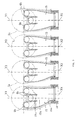
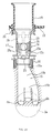
- Viertakt- Brennkraftmaschine mit einer Lufteinlaßvorrichtung, mit zumindest einem Lufteinlaßkanal (15) zum Durchgehen in eine jeweilige Brennkammer (6a), einem Drosselventil (20), angeordnet in dem Lufteinlaßkanal (15), zumindest einem Kraftstoffeinspritzventil (25), das stromab des Drosselventiles (20) auf einer Seite des Lufteinlaßkanales (15) angeordnet ist, und einem Dämpfungsventil (34, 40), das stromauf des Drosselventiles (20) angeordnet ist und das einen veränderbaren Spalt auf einer Seite des Einlaßkanales (15) vorsieht, um den Querschnitt des Lufteinlaßkanales (15) entsprechend der Lufteinlaßbedingungen zu variieren, und um erhöhte Einlaßluftströmungen, die aus einer Öffnung des vorhergehenden Drosselventiles (20) resultieren, zu dämpfen,
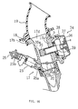
dadurch gekennzeichnet, daß das Kraftstoffeinspritzventil (25) in enger Nähe zu dem Drosselventil (20) vorgesehen ist und das Kraftstoffeinspritzventil (25) und der variable Spalt auf derselben Seite des jeweiligen Lufteinlaßkanales (15) vorgesehen sind. - Viertakt- Brennkraftmaschine nach Anspruch 1, gekennzeichnet durch einen Sensor (22), um die Drosselventilöffnung zu erfassen, und eine Steuereinheit (24), zusammengesetzt aus einer integrierten ECU in einem ECU- Gehäuse (23), wobei der Sensor mit einem Drosselkörper (17), der das Drosselventil (20) enthält, verbunden ist.
- Viertakt- Brennkraftmaschine nach Anspruch 1 oder 2, dadurch gekennzeichnet, daß das Drosselventil (20) in enger Nähe zu den Lufteinlaßventilöffnungen (6b) vorgesehen ist, so daß ein Volumenverhältnis minimiert ist, wobei das Volumenverhältnis ein Verhältnis eines Öffnungsvolumens ist, gebildet durch das Volumen der Lufteinlaßventilöffnungen (6b) bis zu dem Drosselventil (20) in dem Lufteinlaßkanal (15), zu einem Hubvolumen, gebildet durch eine Verlagerung eines Kolbens (8) innerhalb eines Zylinders (5a) des Motors.
- Viertakt- Brennkraftmaschine nach Anspruch 3, dadurch gekennzeichnet, daß das Volumenverhältnis zwischen 0,15 und 0,45 festlegbar ist.
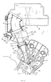
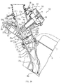
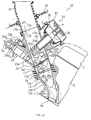
- Viertakt- Brennkraftmaschine nach zumindest einem der Ansprüche 1 bis 4, dadurch gekennzeichnet, daß der Lufteinlaßkanal (15) unter einem Winkel von 30 bis 60 Grad in Bezug zu den Zylinderachsen des Motors geneigt ist, wobei das Dämpfungsventil (34) in den Decken des Lufteinlaßkanales (15) in Richtung der Seite der Zylinderachse positioniert ist, und wobei die vorhergehenden Kraftstoffeinspritzventile (25) in der Bodenwand an der der Zylinderachse gegenüberliegenden Seite positioniert sind.
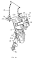
- Viertakt- Brennkraftmaschine nach zumindest einem der Ansprüche 1 bis 5, gekennzeichnet durch eine Mehrzahl von Sätzen von Drosselkörpern (17), die Drosselventile (20), sowie mit diesen verbundene Kraftstoffeinspritzventile (25), enthalten.
- Viertakt- Brennkraftmaschine nach Anspruch 6, dadurch gekennzeichnet, daß die Kraftstoffeinspritzventile (25) in der Mehrzahl von Sätzen von Drosselkörpem (17) jeweils mit einem gemeinsamen Kraftstoffzuführungsverteiler (26) verbunden sind, und zusätzlich, wobei die Mehrzahl von Sätzen von Drosselkörpern (17) mittels des Kraftstoffzuführungsverteilers (26) vereinheitlicht ist, wobei die Kraftstoffzuführungsöffnung des Kraftstoffzuführungsverteilers (26) einen verbundenen Kraftstofffilter (51) aufweist und ein Kraftstoffdruckregulierungsventil (30), verbunden mit einer Kraftstoffrückführungsöffnung, aufweist.
- Viertakt- Brennkraftmaschine nach Anspruch 7, dadurch gekennzeichnet, daß der Kraftstoffzuführungsverteiler (26), der den Hochdruckkraftstoff zu den Kraftstoffeinspritzventilen (25) zuführt, in einem Eckbereich, gebildet durch die Bodenfläche eines Luftreinigers (18), der mit dem stromaufwärtigen Ende des Lufteinlaßkanales (15) verbunden ist und der Wandfläche des Kraftstofftanks.
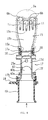
- Viertakt- Brennkraftmaschine nach zumindest einem der Ansprüche 6 bis 8, gekennzeichnet durch Raumluftdruck- Führungskanäle (60), die den Luftdruck, der aus der durchströmenden Luft durch die Lufteinlaßkanäle (15) resultiert, leiten, und Drosselventile (20), installiert inmitten der vorhergehenden Lufteinlaßkanäle (15), wobei Dämpfungsventile stromauf der vorhergehenden Drosselventile (20) in den vorhergehenden Lufteinlaßkanälen (15) vorgesehen sind, die den Querschittsbereich des Lufteinlaßkanales (15) auf seiner stromaufwärtigen Seite verändern können, um die erhöhte Strömungsgeschwindigkeit der Luft zu dämpfen, die sich in Abhängigkeit der Öffnung der vorhergehenden Drosselventile (20) entwickelt, wobei die Dämpfungsventile (34) aus einem freien Kolben (35) bestehen, der sich in den Lufteinlaßkanal (15) in einer Richtung ungefähr rechtwinklig zu seiner Achse zurückzieht, wobei der freie Kolben (35) eine Arbeitskammer (37) hat, untergebracht in dem äußeren Endbereich des freien Kolbens (35), die mit einer Zwischenwand (38) ausgerüstet ist, die eine luftdichte Verbindung mit dem außenseitigen Ende des freien Kolbens (35) schafft und die vorhergehende Arbeitskammer (37) in eine Negativdruckkammer und eine Positivdruckkammer teilt, wobei der negative Einlaßdruck abgegriffen in dem Bereich zwischen den Wandoberflächen des vorhergehenden Lufteinlaßkanales (15) und dem vorhergehenden freien Kolben (35), in die vorhergehende Negativdruckkammer eingeführt wird, und zusätzlich der vorhergehende Raumluftdruck in die vorhergehende Positivdruckkammer zugeführt wird.
Applications Claiming Priority (12)
| Application Number | Priority Date | Filing Date | Title |
|---|---|---|---|
| JP7581997 | 1997-03-27 | ||
| JP75819/97 | 1997-03-27 | ||
| JP7581997 | 1997-03-27 | ||
| JP14231397 | 1997-05-30 | ||
| JP142313/97 | 1997-05-30 | ||
| JP14231397 | 1997-05-30 | ||
| JP178510/97 | 1997-07-03 | ||
| JP17851097 | 1997-07-03 | ||
| JP17851097 | 1997-07-03 | ||
| JP18814397 | 1997-07-14 | ||
| JP188143/97 | 1997-07-14 | ||
| JP18814397A JP3886217B2 (ja) | 1997-03-27 | 1997-07-14 | 4サイクルエンジンの吸気装置 |
Publications (3)
| Publication Number | Publication Date |
|---|---|
| EP0867608A2 EP0867608A2 (de) | 1998-09-30 |
| EP0867608A3 EP0867608A3 (de) | 1999-07-21 |
| EP0867608B1 true EP0867608B1 (de) | 2002-11-06 |
Family
ID=27465865
Family Applications (1)
| Application Number | Title | Priority Date | Filing Date |
|---|---|---|---|
| EP98105656A Expired - Lifetime EP0867608B1 (de) | 1997-03-27 | 1998-03-27 | Lufteinlasssystem für eine Viertaktbrennkraftmaschine |
Country Status (4)
| Country | Link |
|---|---|
| US (2) | US6039029A (de) |
| EP (1) | EP0867608B1 (de) |
| JP (1) | JP3886217B2 (de) |
| DE (1) | DE69809102T2 (de) |
Cited By (1)
| Publication number | Priority date | Publication date | Assignee | Title |
|---|---|---|---|---|
| TWI487835B (zh) * | 2012-08-29 | 2015-06-11 | Sanyang Industry Co Ltd | 機車引擎之進氣道控制裝置 |
Families Citing this family (57)
| Publication number | Priority date | Publication date | Assignee | Title |
|---|---|---|---|---|
| EP1001160B1 (de) * | 1998-11-16 | 2003-05-14 | Sanshin Kogyo Kabushiki Kaisha | Brennkraftmaschine |
| JP3704993B2 (ja) * | 1999-02-22 | 2005-10-12 | スズキ株式会社 | 自動二輪車の燃料ポンプ装置 |
| US6371068B2 (en) | 2000-01-24 | 2002-04-16 | G. Brandt Taylor | Air intake for internal combustion engine |
| DE10115282B4 (de) * | 2000-03-29 | 2006-03-02 | Hitachi, Ltd. | Einlaßluftsteuervorrichtung und Brennkraftmaschine, in der sie montiert ist |
| CN2462370Y (zh) * | 2001-01-18 | 2001-11-28 | 应城市神风发动机有限责任公司 | 一种数字模块控制汽油发动机工况的装置 |
| US6886532B2 (en) | 2001-03-13 | 2005-05-03 | Nissan Motor Co., Ltd. | Intake system of internal combustion engine |
| AT5648U1 (de) * | 2001-08-02 | 2002-09-25 | Avl List Gmbh | Brennkraftmaschine mit zumindest zwei einlassventilen pro zylinder |
| JP3970725B2 (ja) * | 2002-09-11 | 2007-09-05 | 本田技研工業株式会社 | エンジン用燃料噴射装置 |
| US7588009B2 (en) | 2003-06-23 | 2009-09-15 | Honda Motor Co., Ltd. | Layout structure of a fuel injection device in a motor cycle |
| US6971371B2 (en) * | 2003-09-30 | 2005-12-06 | Honda Motor Co., Ltd. | Air-fuel mixing and delivery apparatus for an internal combustion engine |
| JP4318522B2 (ja) * | 2003-10-06 | 2009-08-26 | 本田技研工業株式会社 | 多気筒内燃機関 |
| JP4316390B2 (ja) * | 2004-01-09 | 2009-08-19 | 本田技研工業株式会社 | 不整地走行用鞍乗り型四輪車 |
| MY142590A (en) * | 2004-02-06 | 2010-12-15 | Honda Motor Co Ltd | A fuel injection system for a saddle ride type four-wheel vehicle |
| JP4238166B2 (ja) * | 2004-03-22 | 2009-03-11 | ヤマハ発動機株式会社 | 燃料供給装置および車両 |
| JP4464243B2 (ja) * | 2004-08-25 | 2010-05-19 | 川崎重工業株式会社 | エンジンの吸気装置 |
| JP4511975B2 (ja) * | 2005-03-02 | 2010-07-28 | 株式会社ケーヒン | 2燃料噴射弁を備えるスロットルボデーにおける燃料供給管構造 |
| JP4334493B2 (ja) * | 2005-03-17 | 2009-09-30 | 株式会社ケーヒン | 2燃料噴射弁を備える多連スロットルボデーにおける燃料供給管構造 |
| JP4369514B2 (ja) * | 2005-03-18 | 2009-11-25 | トヨタ自動車株式会社 | 2系統燃料噴射式内燃機関 |
| JP4602402B2 (ja) | 2005-03-18 | 2010-12-22 | トヨタ自動車株式会社 | 内燃機関 |
| ES2724733T3 (es) * | 2005-03-18 | 2019-09-13 | Toyota Motor Co Ltd | Motor de inyección de combustible de sistema doble |
| CN101115921B (zh) | 2005-03-18 | 2011-08-31 | 丰田自动车株式会社 | 两系统燃料喷射式内燃机 |
| JP4537933B2 (ja) * | 2005-10-18 | 2010-09-08 | 本田技研工業株式会社 | 吸気制御装置 |
| JP2007177688A (ja) * | 2005-12-28 | 2007-07-12 | Honda Motor Co Ltd | エンジンの燃料噴射装置 |
| JP4698544B2 (ja) * | 2006-09-26 | 2011-06-08 | 本田技研工業株式会社 | 内燃機関 |
| US7401590B2 (en) * | 2006-10-09 | 2008-07-22 | Harley-Davidson Motor Company Group, Inc. | Active air intake for an engine |
| US7302930B1 (en) | 2006-12-13 | 2007-12-04 | Chrysler Llc | Air induction system and assembly method for an intake manifold with a single shaft and sensor for activating air control valves |
| EP1953379B1 (de) * | 2007-02-01 | 2012-12-19 | Yamaha Hatsudoki Kabushiki Kaisha | Fahrzeug |
| JP4906549B2 (ja) † | 2007-03-15 | 2012-03-28 | 本田技研工業株式会社 | 多気筒内燃機関の吸気マニホルド |
| JP2010031774A (ja) * | 2008-07-30 | 2010-02-12 | Mikuni Corp | 燃料供給装置 |
| DE102008043976A1 (de) * | 2008-11-21 | 2010-05-27 | Robert Bosch Gmbh | Gaszufuhrmodul |
| JP5352567B2 (ja) * | 2009-11-10 | 2013-11-27 | 株式会社ミクニ | 燃料噴射装置 |
| JP5543772B2 (ja) * | 2009-12-29 | 2014-07-09 | 川崎重工業株式会社 | 吸気ダクト及び乗り物 |
| FR2955362B1 (fr) * | 2010-01-19 | 2012-02-10 | Mann & Hummel Gmbh | Dispositif d'alimentation d'un moteur a essence multicylindres a injection indirecte |
| US8672234B2 (en) * | 2010-05-20 | 2014-03-18 | Enginetics, Llc | Multi-physics fuel atomizer and methods |
| US8714138B2 (en) * | 2011-05-30 | 2014-05-06 | Suzuki Motor Corporation | Intake structure of motorcycle |
| JP5758253B2 (ja) * | 2011-09-25 | 2015-08-05 | 本田技研工業株式会社 | 多気筒内燃機関 |
| AT511721B1 (de) * | 2011-11-03 | 2013-02-15 | Avl List Gmbh | Einlassstrang für eine brennkraftmaschine |
| GB2497319B (en) * | 2011-12-06 | 2013-11-13 | Ip Consortium Ltd | Engine Intake Fuel Injection and Heating |
| JP5355673B2 (ja) * | 2011-12-13 | 2013-11-27 | ヤマハ発動機株式会社 | エンジン |
| JP5143275B2 (ja) * | 2011-12-13 | 2013-02-13 | ヤマハ発動機株式会社 | エンジン |
| JP2013209926A (ja) * | 2012-03-30 | 2013-10-10 | Mitsubishi Heavy Ind Ltd | 船舶、燃料ガス供給装置および燃料ガス供給方法 |
| JP6047336B2 (ja) * | 2012-08-10 | 2016-12-21 | 本田技研工業株式会社 | 内燃機関の吸気装置 |
| US9038591B2 (en) | 2012-10-10 | 2015-05-26 | Fca Us Llc | Intake air control system for multi-cylinder combustion engine |
| US9206737B2 (en) | 2013-04-05 | 2015-12-08 | Enginetics, Llc | System control strategy and methods for multi-physics fuel atomizer |
| US10302058B2 (en) | 2013-04-05 | 2019-05-28 | Enginetics, Llc | Co-axial dual fluids metering system and methods |
| GB2514347A (en) * | 2013-05-20 | 2014-11-26 | Vepec Ltd | A Rotating Barrel Carburettor |
| US10378549B2 (en) * | 2014-10-17 | 2019-08-13 | Kohler Co. | Dual compressor turbocharger |
| US9556792B2 (en) | 2014-10-17 | 2017-01-31 | Kohler, Co. | Dual compressor turbocharger |
| JP2018013117A (ja) * | 2016-07-22 | 2018-01-25 | 株式会社ニッキ | V型2シリンダ汎用エンジンの燃料供給制御システム |
| JP2018053834A (ja) * | 2016-09-30 | 2018-04-05 | 本田技研工業株式会社 | 内燃機関 |
| JP7131917B2 (ja) | 2018-01-23 | 2022-09-06 | 株式会社ミクニ | スロットル装置 |
| CN110360000B (zh) * | 2018-04-09 | 2021-08-17 | 上海汽车集团股份有限公司 | 直喷汽油发动机进气控制方法 |
| KR102050914B1 (ko) * | 2018-08-23 | 2019-12-02 | 주식회사 현대케피코 | 전자식 스로틀밸브 장치 |
| USD1023061S1 (en) | 2020-02-09 | 2024-04-16 | Velossa Tech Engineering, Inc. | Ram-air intake |
| US20210246855A1 (en) | 2020-02-09 | 2021-08-12 | Velossa Tech Engineering Inc. | Interchangeable intake manifold assemblies |
| USD1019704S1 (en) | 2020-02-09 | 2024-03-26 | Velossa Tech Engineering, Inc. | Ram-air intake |
| TWI751808B (zh) * | 2020-11-25 | 2022-01-01 | 宏佳騰動力科技股份有限公司 | 單進氣通道式進氣調節構造 |
Family Cites Families (19)
| Publication number | Priority date | Publication date | Assignee | Title |
|---|---|---|---|---|
| FR2092248A5 (de) * | 1970-05-22 | 1971-01-21 | Honda Motor Co Ltd | |
| GB1420313A (en) * | 1972-02-01 | 1976-01-07 | Plessey Co Ltd | Nozzles for the injection of liquid fuel into gaseous media |
| JPS55119933A (en) * | 1979-03-07 | 1980-09-16 | Toyota Motor Corp | Variable venturi type carburetor |
| JPS5623562A (en) * | 1979-08-01 | 1981-03-05 | Toyota Motor Corp | Fuel injecting carburetor |
| JPS5818555A (ja) * | 1981-07-24 | 1983-02-03 | Hitachi Ltd | 燃料供給装置 |
| JPS5912122A (ja) * | 1982-07-14 | 1984-01-21 | Mikuni Kogyo Co Ltd | 内燃機関の吸気路装置 |
| JPS60252129A (ja) * | 1984-05-29 | 1985-12-12 | Honda Motor Co Ltd | スロツトル弁を備える内燃エンジンの作動制御装置 |
| US4819588A (en) * | 1986-03-08 | 1989-04-11 | Mazda Motor Corporation | Intake apparatus for an engine |
| US4768486A (en) * | 1986-12-05 | 1988-09-06 | Honda Giken Kogyo Kabushiki Kaisha | Fuel supply control system for internal combustion engine |
| JPS63277828A (ja) * | 1987-05-11 | 1988-11-15 | Hitachi Ltd | 内燃機関用多連スロツトル機構 |
| US4922876A (en) * | 1988-03-25 | 1990-05-08 | Aisan Kogyo Kabushiki Kaisha | Fuel injection device |
| JP2753874B2 (ja) * | 1989-12-06 | 1998-05-20 | マツダ株式会社 | 多気筒エンジンの吸気装置 |
| EP0459374B1 (de) * | 1990-06-01 | 1995-02-08 | Mazda Motor Corporation | Ansauganlage für einen Motor |
| JP2933735B2 (ja) * | 1991-02-22 | 1999-08-16 | ヤマハ発動機株式会社 | 自動二輪車用燃料噴射式エンジンの吸気装置 |
| US5477823A (en) * | 1994-01-25 | 1995-12-26 | Yamaha Hatsudoki Kabushiki Kaisha | Control valve for engine intake control system |
| JP3308754B2 (ja) * | 1995-02-15 | 2002-07-29 | ヤマハ発動機株式会社 | エンジンの排気再循環装置 |
| JPH08232814A (ja) * | 1995-02-28 | 1996-09-10 | Suzuki Motor Corp | 内燃機関の燃料噴射装置 |
| DE19535744A1 (de) * | 1995-09-26 | 1997-03-27 | Bosch Gmbh Robert | Brennstoffeinspritzanordnung für eine Brennkraftmaschine und Verfahren zur Brennstoffeinspritzung |
| DE69816141T2 (de) * | 1997-01-31 | 2004-01-08 | Yamaha Hatsudoki K.K., Iwata | Viertaktbrennkraftmaschine |
-
1997
- 1997-07-14 JP JP18814397A patent/JP3886217B2/ja not_active Expired - Fee Related
-
1998
- 1998-03-27 US US09/049,337 patent/US6039029A/en not_active Expired - Lifetime
- 1998-03-27 DE DE69809102T patent/DE69809102T2/de not_active Expired - Lifetime
- 1998-03-27 EP EP98105656A patent/EP0867608B1/de not_active Expired - Lifetime
-
1999
- 1999-10-27 US US09/428,617 patent/US6196186B1/en not_active Expired - Lifetime
Cited By (1)
| Publication number | Priority date | Publication date | Assignee | Title |
|---|---|---|---|---|
| TWI487835B (zh) * | 2012-08-29 | 2015-06-11 | Sanyang Industry Co Ltd | 機車引擎之進氣道控制裝置 |
Also Published As
| Publication number | Publication date |
|---|---|
| JPH1172068A (ja) | 1999-03-16 |
| DE69809102D1 (de) | 2002-12-12 |
| EP0867608A3 (de) | 1999-07-21 |
| JP3886217B2 (ja) | 2007-02-28 |
| DE69809102T2 (de) | 2003-03-20 |
| US6039029A (en) | 2000-03-21 |
| EP0867608A2 (de) | 1998-09-30 |
| US6196186B1 (en) | 2001-03-06 |
Similar Documents
| Publication | Publication Date | Title |
|---|---|---|
| EP0867608B1 (de) | Lufteinlasssystem für eine Viertaktbrennkraftmaschine | |
| US7802555B2 (en) | Intake control device for an engine | |
| JP2777817B2 (ja) | 多気筒エンジンの吸気装置 | |
| JP2887797B2 (ja) | 4サイクルエンジンの吸気装置 | |
| US6655337B2 (en) | V-type 2-cylinder engine | |
| GB2059503A (en) | Fuel Supply Devices for Multi- cylinder Internal Combustion Engines | |
| EP0856649B1 (de) | Viertaktbrennkraftmaschine | |
| EP1553288A1 (de) | Motor | |
| WO2004038213A1 (ja) | 自動二輪車 | |
| US20040050376A1 (en) | Stratified scavenging mechanism of a two-stroke engine | |
| JPH10227258A (ja) | 内燃機関 | |
| CN110494643B (zh) | 一种用于两轮车辆的空气感应系统 | |
| JP3555111B2 (ja) | V形2気筒エンジン | |
| WO2004038214A1 (ja) | 自動二輪車 | |
| JP4271769B2 (ja) | エンジンの吸気装置 | |
| EP0500139B1 (de) | Einlassystem für Brennkraftmaschine mit mehreren Ventilen | |
| JP3715059B2 (ja) | 4サイクルエンジン | |
| JPH08232702A (ja) | 燃料噴射式2サイクルエンジンの運転制御装置 | |
| EP0953761B1 (de) | Brennkraftmaschine mit Hilfseinlasskanal | |
| EP0548993A1 (de) | Zweitakt-Brennkraftmaschine deren Einlass durch das Kurbelgehäuse von einer Blattventilvorrichtung gesteuert wird | |
| JP2004003424A (ja) | エンジンの吸気装置 | |
| JP3535948B2 (ja) | 多気筒内燃機関 | |
| JP2004124738A (ja) | 多気筒エンジンの吸気装置 | |
| JPH07305671A (ja) | 船外機用エンジンの吸気装置 | |
| JP4103332B2 (ja) | V型エンジンのキャブレター |
Legal Events
| Date | Code | Title | Description |
|---|---|---|---|
| PUAI | Public reference made under article 153(3) epc to a published international application that has entered the european phase |
Free format text: ORIGINAL CODE: 0009012 |
|
| AK | Designated contracting states |
Kind code of ref document: A2 Designated state(s): DE FR GB IT |
|
| AX | Request for extension of the european patent |
Free format text: AL;LT;LV;MK;RO;SI |
|
| PUAL | Search report despatched |
Free format text: ORIGINAL CODE: 0009013 |
|
| AK | Designated contracting states |
Kind code of ref document: A3 Designated state(s): AT BE CH DE DK ES FI FR GB GR IE IT LI LU MC NL PT SE |
|
| AX | Request for extension of the european patent |
Free format text: AL;LT;LV;MK;RO;SI |
|
| 17P | Request for examination filed |
Effective date: 20000119 |
|
| AKX | Designation fees paid |
Free format text: DE FR GB IT |
|
| 17Q | First examination report despatched |
Effective date: 20000607 |
|
| GRAG | Despatch of communication of intention to grant |
Free format text: ORIGINAL CODE: EPIDOS AGRA |
|
| GRAG | Despatch of communication of intention to grant |
Free format text: ORIGINAL CODE: EPIDOS AGRA |
|
| GRAH | Despatch of communication of intention to grant a patent |
Free format text: ORIGINAL CODE: EPIDOS IGRA |
|
| GRAH | Despatch of communication of intention to grant a patent |
Free format text: ORIGINAL CODE: EPIDOS IGRA |
|
| GRAA | (expected) grant |
Free format text: ORIGINAL CODE: 0009210 |
|
| AK | Designated contracting states |
Kind code of ref document: B1 Designated state(s): DE FR GB IT |
|
| REG | Reference to a national code |
Ref country code: GB Ref legal event code: FG4D |
|
| REF | Corresponds to: |
Ref document number: 69809102 Country of ref document: DE Date of ref document: 20021212 |
|
| ET | Fr: translation filed | ||
| PLBE | No opposition filed within time limit |
Free format text: ORIGINAL CODE: 0009261 |
|
| STAA | Information on the status of an ep patent application or granted ep patent |
Free format text: STATUS: NO OPPOSITION FILED WITHIN TIME LIMIT |
|
| 26N | No opposition filed |
Effective date: 20030807 |
|
| REG | Reference to a national code |
Ref country code: FR Ref legal event code: PLFP Year of fee payment: 18 |
|
| PGFP | Annual fee paid to national office [announced via postgrant information from national office to epo] |
Ref country code: DE Payment date: 20150320 Year of fee payment: 18 Ref country code: IT Payment date: 20150326 Year of fee payment: 18 |
|
| PGFP | Annual fee paid to national office [announced via postgrant information from national office to epo] |
Ref country code: FR Payment date: 20150319 Year of fee payment: 18 Ref country code: GB Payment date: 20150319 Year of fee payment: 18 |
|
| REG | Reference to a national code |
Ref country code: DE Ref legal event code: R119 Ref document number: 69809102 Country of ref document: DE |
|
| GBPC | Gb: european patent ceased through non-payment of renewal fee |
Effective date: 20160327 |
|
| REG | Reference to a national code |
Ref country code: FR Ref legal event code: ST Effective date: 20161130 |
|
| PG25 | Lapsed in a contracting state [announced via postgrant information from national office to epo] |
Ref country code: DE Free format text: LAPSE BECAUSE OF NON-PAYMENT OF DUE FEES Effective date: 20161001 Ref country code: GB Free format text: LAPSE BECAUSE OF NON-PAYMENT OF DUE FEES Effective date: 20160327 Ref country code: FR Free format text: LAPSE BECAUSE OF NON-PAYMENT OF DUE FEES Effective date: 20160331 |
|
| PG25 | Lapsed in a contracting state [announced via postgrant information from national office to epo] |
Ref country code: IT Free format text: LAPSE BECAUSE OF NON-PAYMENT OF DUE FEES Effective date: 20160327 |