EP0823771B1 - Motor - Google Patents
Motor Download PDFInfo
- Publication number
- EP0823771B1 EP0823771B1 EP97903595A EP97903595A EP0823771B1 EP 0823771 B1 EP0823771 B1 EP 0823771B1 EP 97903595 A EP97903595 A EP 97903595A EP 97903595 A EP97903595 A EP 97903595A EP 0823771 B1 EP0823771 B1 EP 0823771B1
- Authority
- EP
- European Patent Office
- Prior art keywords
- motor
- teeth
- winding
- core
- stator
- Prior art date
- Legal status (The legal status is an assumption and is not a legal conclusion. Google has not performed a legal analysis and makes no representation as to the accuracy of the status listed.)
- Expired - Lifetime
Links
Images


Classifications
-
- H—ELECTRICITY
- H02—GENERATION; CONVERSION OR DISTRIBUTION OF ELECTRIC POWER
- H02K—DYNAMO-ELECTRIC MACHINES
- H02K21/00—Synchronous motors having permanent magnets; Synchronous generators having permanent magnets
- H02K21/12—Synchronous motors having permanent magnets; Synchronous generators having permanent magnets with stationary armatures and rotating magnets
- H02K21/14—Synchronous motors having permanent magnets; Synchronous generators having permanent magnets with stationary armatures and rotating magnets with magnets rotating within the armatures
- H02K21/16—Synchronous motors having permanent magnets; Synchronous generators having permanent magnets with stationary armatures and rotating magnets with magnets rotating within the armatures having annular armature cores with salient poles
-
- H—ELECTRICITY
- H02—GENERATION; CONVERSION OR DISTRIBUTION OF ELECTRIC POWER
- H02K—DYNAMO-ELECTRIC MACHINES
- H02K1/00—Details of the magnetic circuit
- H02K1/06—Details of the magnetic circuit characterised by the shape, form or construction
- H02K1/12—Stationary parts of the magnetic circuit
- H02K1/14—Stator cores with salient poles
- H02K1/146—Stator cores with salient poles consisting of a generally annular yoke with salient poles
- H02K1/148—Sectional cores
-
- H—ELECTRICITY
- H02—GENERATION; CONVERSION OR DISTRIBUTION OF ELECTRIC POWER
- H02K—DYNAMO-ELECTRIC MACHINES
- H02K1/00—Details of the magnetic circuit
- H02K1/06—Details of the magnetic circuit characterised by the shape, form or construction
- H02K1/22—Rotating parts of the magnetic circuit
- H02K1/27—Rotor cores with permanent magnets
- H02K1/2706—Inner rotors
- H02K1/272—Inner rotors the magnetisation axis of the magnets being perpendicular to the rotor axis
- H02K1/274—Inner rotors the magnetisation axis of the magnets being perpendicular to the rotor axis the rotor consisting of two or more circumferentially positioned magnets
- H02K1/2753—Inner rotors the magnetisation axis of the magnets being perpendicular to the rotor axis the rotor consisting of two or more circumferentially positioned magnets the rotor consisting of magnets or groups of magnets arranged with alternating polarity
- H02K1/276—Magnets embedded in the magnetic core, e.g. interior permanent magnets [IPM]
- H02K1/2766—Magnets embedded in the magnetic core, e.g. interior permanent magnets [IPM] having a flux concentration effect
-
- Y—GENERAL TAGGING OF NEW TECHNOLOGICAL DEVELOPMENTS; GENERAL TAGGING OF CROSS-SECTIONAL TECHNOLOGIES SPANNING OVER SEVERAL SECTIONS OF THE IPC; TECHNICAL SUBJECTS COVERED BY FORMER USPC CROSS-REFERENCE ART COLLECTIONS [XRACs] AND DIGESTS
- Y02—TECHNOLOGIES OR APPLICATIONS FOR MITIGATION OR ADAPTATION AGAINST CLIMATE CHANGE
- Y02T—CLIMATE CHANGE MITIGATION TECHNOLOGIES RELATED TO TRANSPORTATION
- Y02T10/00—Road transport of goods or passengers
- Y02T10/60—Other road transportation technologies with climate change mitigation effect
- Y02T10/64—Electric machine technologies in electromobility
Definitions
- the present invention relates to a synchronous motor comprising a stator for generating a rotary magnetic field, for rotating and driving by making use of a reluctance torque.
- a stator In a conventional general synchronous motor, a stator is formed by integrally projecting plural teeth from a ring-shaped yoke to its inner circumferential side. This stator is fabricated by laminating stator plates having plural teeth projecting to the inner circumferential side. It also comprises a stator core forming slots among these teeth, and windings are wound in these slots by distributed winding. The distributed winding is a winding method for winding distant teeth through slots.
- the rotor is composed by burying plural permanent magnets for magnetic poles in the outer circumference of the rotor core, and mounting a rotary shaft in the center.
- the permanent magnet buried motor can utilize not only the magnet torque but also the reluctance torque, in which the reluctance torque is generated in addition to the magnet torque by the permanent magnets, as an inductance difference occurs between the inductance Ld in the direction of d-axis which is a direction for coupling the center of permanent magnet and the rotor center, and the inductance Lq in the direction of q-axis which is a direction rotated 90 degrees of electrical angle from d-axis.
- This relation is shown in formula (1).
- Formula (1) shows a voltage equation of dp conversion.
- a surface magnet motor since the permeability of permanent magnet is nearly equal to that of air, both inductance Ld and Lq in formula (1) are nearly equal values, and the reluctance torque portion expressed in the second tern enclosed in braces in formula (1) does not occur.
- the distributed winding moreover, by turning windings plural times, a winding ring is formed, and this winding ring is inserted into teeth, and the periphery of the winding ring becomes longer than the periphery of teeth. Still more, in the distributed winding, since the teeth are wound through slots, the windings cross each other. Thus, in the distributed winding, the winding projects from the stator end, and the windings cross each other to increase the size of the coil end.
- the magnetic pole portion at the end of teeth in the stator is formed wider in the peripheral direction. Between the adjacent magnetic pole portions, however, since openings are formed for laying down windings in the slots, the interval of ends of teeth must be formed wider in the peripheral direction. That is, because of the distributed winding, an opening for inserting the winding ring in the teeth is needed.
- the gap between the stator inner circumference and the rotor outer circumference is generally set uniform on the whole periphery except for the openings of the slots.
- FR 2369717A describes a method of manufacturing a dynamoelectric field member.
- the document discloses the production of field members having plural coils by a continuous winding produced from an uninterruptedly continuous conductor wound to encircle a plurality of core elements.
- JP-A-7255138 discloses a permanent magnetic type synchronous rotating curvature comprising a cylindrical rotor core made of axially laminated steel sheets.
- the rotor core is cut partly to forma convex-shaped slit projected toward the centre and a triangular groove is formed between the slits.
- a number of permanent magnets are inserted into the slit to constitute a magnetic field.
- EP-A-0652622 discloses a thin structure rotary motor which aligns a winding configuration with coils which are disposed on respective magnetic pole teeth of a stator core.
- a rotor portion is disposed along the inner circumference of the stator portion.
- EP-A-0629034 discloses a stator which includes core pieces obtained by laminating iron plates divided in a circumferential direction and having projecting and recessed engaging parts at their dividing faces.
- JP 7236240 discloses a rotor for a compressor motor.
- the aim of this arrangement is to prevent magnetic flux from shorting by providing notches on the circumference of the rotor for forming salient poles.
- the present invention provides a motor for driving a rotary shaft by using a reluctance torque, said motor comprising:
- the winding is turned in the portion of a slot recess formed at both sides of the teeth of the core element, and the winding is turned in a state of core element, the winding can be applied on the stator in neat arrangement. Moreover, since the winding is not turned in the adjacent state of teeth, it is not necessary to keep a wide opening between the ends of teeth, so that the interval of ends of teeth can be narrowed.
- stator core composed by coupling ends of plural core elements, and folding the core element group with bent ends into an annular form
- the winding is turned in the slot shape recess portion formed at both sides of the teeth of the core elements, when winding around the teeth, the end interval of teeth can be widened, and the winding can be applied around the teeth in neat arrangement.
- the ends are coupled, position setting when assembling is easy.
- the clearance between the confronting surface of teeth of the permanent magnet and the outer circumference of the rotor core is wider in the central part than in the end portion of the permanent magnet, and the reluctance torque can be utilized effectively.
- the width between the adjacent permanent magnets is 0.15 to 0.20 of the width of teeth confronting two magnetic poles (two permanent magnets), the torque ripple of the motor can be suppressed.
- leading end of the magnetic pole portion of the inner circumferential side of the teeth is projecting in the peripheral direction across a slight gap between the ends of teeth, and the gap between the teeth and rotor outer circumference is nearly constant, so that useless magnetic flux does not flow at the ends of teeth.
- the gap between the teeth and rotor outer circumference may be continuous.
- the magnetic flux is saturated at the ends of the teeth.
- the profile of the adjacent portions of the permanent magnets is a recess form corresponding to the disk-shape profile positioned outside of the center of the permanent magnet, and the magnetic resistance is increased in the adjacent portions of the permanent magnets, so that the magnetic flux distribution may be close to a sine waveform.
- the length of the rotor outer recess positioned outside of the adjacent portions of the permanent magnets should be properly corresponding to the angle of 0.2 to 0.4 of the central angle of the one pole portion of the rotor core.
- the gap between the rotor outer recess and teeth should be properly two times or more of the gap between the rotor outer circumference and the teeth.
- the occupation rate can be enhanced than in the case of round wire.
- the winding of flat square wire is suited to concentric concentrated winding around the teeth.
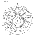
- reference numeral 1 is a synchronous motor which rotates by utilizing reluctance torque, as well as magnet torque, and it is composed of a stator 2, a rotor 3, and a rotary shaft 4.
- the stator 2 is composed of a ring-shaped frame 21, a stator core 22 combining plural independent core elements 5 made of high permeability material in an annular form, and a winding wound around slots 8 formed between teeth 7, 7 of each core element 5, and when a current is applied to these winding groups, a rotary magnetic field is generated.
- the stator core 22 is composed by combining the plural core elements 5 in an annular form on the outer circumference 6 thereof, and fitting and fixing in the inner circumference of the frame 21, and each outer circumference 6 is formed in an entire shape of a sector form in which the extension line of both side surfaces 6a passes through the stator center.
- core elements 5 as specifically shown in Fig. 2.
- slot forming recesses 9 are formed in the inner circumferential portion
- slots 8 are formed in the slot forming recesses 9, 9 in the adjacent teeth 7, 7.
- stopping portions 11 composed of engaging bumps 10a and engaging recesses 10b for engaging with each other when the core elements 5 are combined in an annular form are provided, so that the core elements 5 may be mutually fixed firmly.
- the core elements 5 are combined by welding, or they may be also fixed by crimping by forming fitting parts at the side of the core elements 5.
- the stator 2 is formed by combining plural core elements 5.
- the stator 2 can be formed after turning the winding around the core element 5.
- concentrated windings may be formed easily. That is, as shown in Fig 4, when turning the winding, as shown in Fig 4, there is no disturbing position for winding at the side surface of the teeth 7.
- the winding port of the turning device rotates about the teeth 7, so that an arrangement winding may be formed through an insulating film 24.
- the turning precision of the winding 40. may be enhanced, and the arrangement winding may be formed easily.
- the winding of the stator 2 as a concentrated winding, mutual crossing of winding at the stator end can be suppressed.
- the size of the coil end can be suppressed.
- the periphery of the teeth 5 and one turn of the winding can be equalized in length.
- the winding does not project at the stator end, and the coil end may be reduced in size.
- the winding in the divided state of the stator 5 it is not necessary to consider the space of the winding port of the winding device when winding, and the winding can be overlaid as much as possible.
- the stator 5 is divided when winding, the precision of the winding device is heightened, and an arrangement winding may be formed. As a result, the occupation rate in the slot is heightened. Since the reluctance torque is proportional to the number of turns, the reluctance torque can be enhanced by raising the occupation rate.
- the interval d of ends of teeth does not require the space for passing the winding through the winding port of the device, the interval d of the ends of teeth can be reduced. As a result, gap changes between the teeth and rotor outer circumference are smaller, and the cogging torque decreases.
- the wire filling rate in the slot 8 can be set more than 30%, or even the wire filling rate may be set even more than 60%.
- both sides 12a of the magnetic pole portion 12 are formed nearly in a triangular shape so that the width in the radial direction may be smaller toward the end, thereby decreasing the magnetic leak between the magnetic pole portions 12, 12 of the adjacent core elements 5, 5 by increasing the magnetic resistance at both sides of the magnetic pole portion 12.
- the slight gap d in embodiment 1 is 0 ⁇ d ⁇ 0.2 mm.
- the slight gap d is formed by assembling after winding on the core element 5, and by opening such small gap, the magnetic leak from the winding of the slot 8 can be suppressed, and the cogging torque becomes smaller.
- the gap d of 0 ⁇ d ⁇ 0.2 mm is a value obtained by experiments, and the cogging torque is decreased efficiently at this value. By not contacting the ends completely, it is effective to suppress flow of useless magnetic flux between the adjacent teeth 7.
- This gap d may be set to 0 if the magnetic flux leak between adjacent core elements 5, 5 can be ignored and there is no problem in assembling precision, so that the cogging torque can be eliminated.
- b On the confronting surfaces of the ends of teeth of the teeth 7 (the end of teeth 7, being the side confronting between the ends of the teeth 7), b is properly at b ⁇ 0.6 mm. By defining b in a range of b ⁇ 0.6 mm, magnetic saturation occurs at the end of the teeth 7, and useless magnetic flux leak can be decreased.
- the rotor 3 comprises a rotor core 13 made of high permeability material so that the magnetic flux of the rotary magnetic field produced by the winding group of the stator 2 may pass easily, and permanent magnets 14 incorporated in the rotor core 13 at equal intervals in the peripheral direction corresponding to the poles on the rotor 3.
- These permanent magnets 143 are disposed so that the S pole and N pole may be alternate in the peripheral direction.
- the teeth confronting surface 14a of the permanent magnet 14 is linear.
- the distance between the teeth confronting surface 14a and the outer circumference of the rotor 13 is wider in the middle part than at the end part of the permanent magnet 14.
- the shape of the permanent magnet 14 may be a shape projecting in the middle portion toward the center of the rotor 13.
- a linear cut-off portion 15 is formed at the adjacent end portions of the permanent magnets 14.
- the outer circumference of the stator 2 is coverel with a ring-shaped frame 21, and reinforces the core elements 5 integrated by welding.
- the frame 21 By using the frame 21 in this manner, even in the motor rotating at high speed, the core elements are fixed firmly. If the stator main body assembled from the core elements 5 has a sufficient strength, it is not necessary to reinforce by the frame 21.
- the motor of the invention can be driven by utilizing the reluctance torque as well as the magnet torque. In spite of the occupation rate of over 60% of the slots 8 in the motor, the size of the stator is small.
- the occupation rate can be enhanced, so that high output and small size may be realized.
- the length of the rotor outer recess positioned outside of the portion between the adjacent permanent magnets is properly a length corresponding to an angle of 0.2 to 0.4 of the central angle of one pole of the rotor core.
- the spatial gap h between the teeth 7 and cut-off portion 15 is required to be more than 2 times of the spatial gap between the teeth 7 and rotor outer circumference. In embodiment 1, it has been known by experiment that the spatial gap of the teeth 7 and the cut-off portion should be 0.7 to 1 mm.
- the motor used in an electric vehicle is required to be small in size in order to keep a wide space in the compartment, and at the same time a motor capable of utilizing the current of the charger efficiently is needed.
- a flat square wire with sectional width of 4 mm or more and height of 1.5 mm is used.
- the large current flowing in the winding is 300 amperes or more. Rotating at 7000 to 15000 by passing a large current, it is effective to use a motor of short winding length and a small heat generation for the number of turns, as the motor of the invention. If arrangement winding is possible, the occupation rate may be further enhanced than in round wires.
- Embodiment 2 is described by referring to Fig 5. It should be noted that this embodiment is provided as background useful for the understanding of the invention and does not form part of the claimed invention.
- reference numeral 31 is a synchronous motor rotating mainly in a principal rotating direction F, by using reluctance torque in addition to magnet torque, and it is composed of a stator 32, a rotor 33, and a rotary shaft 34.
- the stator 32 is composed of a ring-shaped frame, a stator core combining plural independent core elements 35 made of high permeability material in an annular form, and a winding wound around slots 38 formed between teeth 37, 37 of each core element 35, and when a current is applied to these winding groups, it is composed to generate a rotary magnetic field.
- Permanent magnets 39 are buried inside the rotor 3 disposed in this stator 32.
- the shape of permanent magnets 39 is in V-form, and the permanent magnets project to the center of the rotor 33. By thus reverse projecting magnetic poles, the inductance difference of the d-axis and q-axis can be increased.
- the permanent magnet 39 is composed of a permanent magnet forward portion 39a and a permanent magnet backward portion 39b in the rotor normal rotating direction F. At this time, the thickness of the permanent magnet backward portion 39b is greater than the thickness of the permanent magnet forward portion 39a.
- Such constitution is based on the following reason.
- the magnetic flux produced from the permanent magnet backward portion 39b and the magnetic flux produced from the teeth 39 may repel each other, possibly causing demagnetization of the permanent magnet backward portion 39b.
- a thick permanent magnet was used.
- the permanent magnet forward portion 39a which is sucked by the suction force from the teeth does not cause demagnetization, and it is not required to be as thick as the permanent magnet backward portion 39b.
- the permanent magnet forward portion 39a may be thinner than the permanent magnetic backward portion 39b.
- the teeth confronting surface of the incorporated permanent magnet backward portion 39b projects to the stator 35 side and is thicker than the permanent magnet forward portion 39a.
- the teeth confronting surface of the incorporated permanent magnet backward portion 39b may be symmetrical to the confronting surface of the permanent magnet forward portion 39a, and may project to the rotor center side.
- a weight for adjusting the balance between the forward portion and the backward portion during rotary drive may be buried in the rotor.
- the shape of the permanent magnets is not limited to V-form, but may be linear or arcuate.
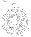
- reference numeral 51 is a synchronous motor which rotates by making use of reluctance torque in addition to magnet torque, and it is composed of a stator 52, a rotor 53, and a rotary shaft 54.
- the stator 52 is composed by combining plural independent core elements 55 made of high permeability material in an annular form. A winding is turned around slots 58 formed between teeth 57, 57 of each core element 55, and it is designed to generate a rotary magnetic field by applying a current in the winding group.
- the permanent magnet per pole is divided into two sections in the rotor radial direction, and is composed of an outside permanent magnet 59 and an inside permanent magnet 60.
- the permanent magnets 59,60 are formed in a convex arc shape at the rotor center side, and the both ends 59a,60a are extended to the position close to the rotor outer circumference.
- the gap between the outside permanent magnet 59 and inside permanent magnet 60 is almost a constant width, and a passage 61 of magnetic flux in the q-axis direction is formed in this gap portion.
- the stator 52 has a specific number of teeth 57, a winding (not shown) is turned around each tooth 57. At this time, since the winding is applied on each core element 55, a concentrated winding is applied. As an alternating current is given to the stator winding, a rotary magnetic flux is generated, and by this rotary magnetic flux, magnet torque and reluctance torque act on the rotor 53, so that the rotor 53 is driven by rotation.
- the width M of the gap between the outside permanent magnet 59 and inside permanent magnet 60 is desired to be as small as possible considering the loss of electromagnetic force of the permanent magnets 59, 60.
- Lq q-axis inductance
- the width M is set at about half of the width N of the teeth 56.
- the q-axis inductance Lq decreases suddenly when the width M becomes smaller than one-third of the width N of the teeth 57.
- the q-axis inductance Lq hardly changes.
- the gap between the outside permanent magnet 59 and inside permanent magnet 60 that is, the width M should be set larger than 1/3 of the width N of the stator 57.
- the magnetic flux path is formed of plural layers of permanent magnets, and although the number of plural layers is not limited, it is known from the experiment that the efficiency is the highest in two layers.
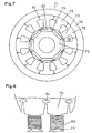
- reference numeral 71 is a synchronous motor which rotates by utilizing reluctance torque in addition to magnet torque, and it is composed of a stator 72 and a rotor 73.
- the stator 72 is composed of a ring-shaped frame 74, a stator core combining plural independent core elements 75 made of high permeability material in an annular form, and a winding 80 turned around slots 78 formed between teeth 77, 77 of each core element 75, and it is designed to generate a rotary magnetic field by applying a current in the winding group.
- the core elements 75 connect the end portions of core elements 75 as shown in Fig. 8, and compose a core element group.
- the core element group has a space in a folding portion 81 at the end, so as to be folded easily.
- the stator 72 By composing the stator 72 by turning and folding the winding 80 in the core element group, the stator can be assembled and positioned easily.
- the core elements 75 may be connected by welding, or fixed by fitting the ring-shaped frame 74.
- An annular stator may be composed of one core element group, or plural core element groups may be combined to compose the annular stator.
- the stator may be formed by fixing the core element group by using resin or the like.
- the winding does not project excessively to the stator end surface, and hence the coil end may be reduced in size.
- the winding can be applied on a single core element or by expanding the interval of the adjacent teeth, turning is easy and an arrangement winding can be applied. It is not necessary to provide a space between slots necessary for turning the winding by the turning device. Hence, the occupation rate can be enhanced, and the reluctance torque acts efficiently, so that a motor of large output and small size can be presented. In the interval of ends of adjacent teeth, it is not necessary to consider turning of the winding, the interval of ends of adjacent teeth can be decreased, and it is effective to suppress cogging torque.
Claims (11)
- Ein Motor zum Antreiben einer Drehwelle (4) unter Verwendung eines Reluktanz-Drehmoments, wobei der genannte Motor umfasst:einen Statorkem (2), der durch Kombination einer Mehrzahl von Kemelementen (5) in einer ringförmigen Form ausgebildet ist, wobei die Mehrzahl von Elementen Zähne (7), äußere Umfangsteile (6) und Schlitze (8) zwischen den Zähnen umfasst;eine dichte Wicklung (24), die um jeden der Zähne gewickelt ist; undeinen Rotorkem (3), der eine Mehrzahl von inneren Permanentmagneten (14) von flacher plattenartiger Form entlang einer Umfangsrichtung des Rotorkems einschließt, wobei der Rotorkem die Drehwelle (4) stützt und den Zähnen (7) gegenüberliegt,wobei der Motor dadurch gekennzeichnet ist, dass:ein äußerer Umfang des Rotorkems (3) einen Sekans bildet, der den Bogen des Rotorkems an einer Position radial auswärts liegend von den Umfangsenden von je zwei benachbarten Permanentmagneten schneidet.
- Der Motor von Anspruch 1, worin der Abstand zwischen den Permanentmagneten, die einander benachbart sind, in der Umfangsrichtung in einem Bereich von 15 % bis 20 % der Breite der Zähne, die zwei Permanentmagneten entsprechen, liegt.
- Der Motor von Anspruch 1, worin die Länge des geradlinigen Umfangsbereichs 20 % bis 40 % der Linienlänge, die durch einen Winkel gemessen wird, entsprechend einem Pol des Rotorkems mit Hinsicht auf die Mitte des Rotorkems, beträgt.
- Der Motor von Anspruch 1, worin ein Abstand (h) zwischen dem Rotorkem und jeder Spitze der Zähne an dem angrenzenden Punkt von zwei der Permanentmagneten größer als das Zweifache von dem an jedem Mittelpunkt der Permanentmagnete ist.
- Der Motor von Anspruch 1, worin der Abstand (h) zwischen dem Rotorkem und jeder Spitze der Zähne zwischen 0,7 mm und 1 mm liegt.
- Der Motor von Anspruch 1, worin jeder der Zähne in einer Umfangsrichtung an einer inneren Kante, die dem Rotorkem gegenüberliegt, mit einem Abstand (d) zwischen jedem der herausragenden Teile, die einander benachbart sind, herausragt.
- Der Motor von Anspruch 6, worin der Abstand (d) nicht mehr als 0,2 mm beträgt.
- Der Motor von Anspruch 6, worin eine Breite (b) der herausragenden Teile, die einander gegenüberliegen, nicht mehr als 0,6 mm beträgt.
- Der Motor von Anspruch 1, worin die Mehrzahl der Kemelemente an jedem Ende der Elemente miteinander verbunden ist, und Biegen der Verbindungsbereiche den Statorkem ausbildet.
- Der Motor von Anspruch 1, worin der Statorkem weiterhin einen ringförmigen Rahmen (21) außerhalb der Kemelemente einschließt.
- Der Motor von Anspruch 1, worin die Wicklung ein Flachdraht ist.
Applications Claiming Priority (3)
| Application Number | Priority Date | Filing Date | Title |
|---|---|---|---|
| JP35988/96 | 1996-02-23 | ||
| JP3598896 | 1996-02-23 | ||
| PCT/JP1997/000489 WO1997031422A1 (fr) | 1996-02-23 | 1997-02-21 | Moteur |
Publications (3)
| Publication Number | Publication Date |
|---|---|
| EP0823771A1 EP0823771A1 (de) | 1998-02-11 |
| EP0823771A4 EP0823771A4 (de) | 2000-06-28 |
| EP0823771B1 true EP0823771B1 (de) | 2006-04-26 |
Family
ID=12457240
Family Applications (1)
| Application Number | Title | Priority Date | Filing Date |
|---|---|---|---|
| EP97903595A Expired - Lifetime EP0823771B1 (de) | 1996-02-23 | 1997-02-21 | Motor |
Country Status (5)
| Country | Link |
|---|---|
| US (6) | US6049153A (de) |
| EP (1) | EP0823771B1 (de) |
| CN (1) | CN1071061C (de) |
| DE (1) | DE69735741T2 (de) |
| WO (1) | WO1997031422A1 (de) |
Families Citing this family (179)
| Publication number | Priority date | Publication date | Assignee | Title |
|---|---|---|---|---|
| DE69735741T2 (de) * | 1996-02-23 | 2006-09-14 | Matsushita Electric Industrial Co., Ltd., Kadoma | Motor |
| JPH09285088A (ja) * | 1996-04-12 | 1997-10-31 | Hitachi Ltd | 永久磁石回転電機及びそれを用いた電動車両 |
| JP3568364B2 (ja) * | 1996-09-30 | 2004-09-22 | 松下電器産業株式会社 | 回転電機のコア |
| US6940205B1 (en) * | 1997-09-08 | 2005-09-06 | Matsushita Electric Industrial Co., Ltd. | Permanent magnet synchronous motor |
| US6242837B1 (en) * | 1997-09-29 | 2001-06-05 | Hitachi, Ltd. | Permanent magnet rotary machine and electric vehicle using the same |
| SE512784C2 (sv) * | 1998-04-21 | 2000-05-15 | Hoeganaes Ab | Induktionsmaskinstator |
| FI980980A (fi) * | 1998-05-04 | 1999-11-05 | Abb Motors Oy | Kestomagneettitahtikone |
| DE19933009A1 (de) * | 1998-07-24 | 2000-02-10 | Matsushita Electric Ind Co Ltd | Motor mit interne Permanentmagneten enthaltendem Rotor und einen solchen Motor verwendende Antriebseinheit |
| US6452302B1 (en) * | 1998-09-28 | 2002-09-17 | Hitachi, Ltd. | Rotary electric machine and electric vehicle using the same |
| US6340857B2 (en) | 1998-12-25 | 2002-01-22 | Matsushita Electric Industrial Co., Ltd. | Motor having a rotor with interior split-permanent-magnet |
| JP2000197290A (ja) * | 1998-12-25 | 2000-07-14 | Hitachi Ltd | 永久磁石式回転電機及びそれを用いた電動車両 |
| GB9903308D0 (en) * | 1999-02-13 | 1999-04-07 | Trw Lucas Varity Electric | Improvements relating to electrical power assisted steering assemblies |
| US6133663A (en) * | 1999-04-01 | 2000-10-17 | A. O. Smith Corporation | Brushless permanent magnet machine |
| JP2000333423A (ja) * | 1999-05-21 | 2000-11-30 | Matsushita Electric Ind Co Ltd | 永久磁石モータ |
| TW564285B (en) * | 1999-06-29 | 2003-12-01 | Sanyo Electric Co | Sealed rotary compressor |
| JP3454234B2 (ja) * | 1999-09-27 | 2003-10-06 | 日産自動車株式会社 | 分割コアモータ |
| JP2001136690A (ja) * | 1999-11-10 | 2001-05-18 | Isuzu Motors Ltd | 回転機のロータ |
| FR2804552B1 (fr) * | 2000-01-28 | 2003-01-03 | Leroy Somer | Procede de fabrication d'un circuit de machine electrique |
| TW508891B (en) * | 2000-02-21 | 2002-11-01 | Misubishi Electric Corp | Stator iron core of electric motor, manufacturing method thereof, electric motor, and compresor |
| JP2001314052A (ja) * | 2000-02-25 | 2001-11-09 | Nissan Motor Co Ltd | 同期電動機のロータ構造 |
| JP3403690B2 (ja) * | 2000-03-02 | 2003-05-06 | 株式会社日立製作所 | 永久磁石式回転電機を用いたハイブリット電気自動車 |
| US6359355B1 (en) * | 2000-03-20 | 2002-03-19 | Emerson Electric Co. | Hot dropped shell and segmented stator tooth motor |
| JP2001275325A (ja) * | 2000-03-27 | 2001-10-05 | Honda Motor Co Ltd | 電動パワーステアリング装置 |
| JP3656733B2 (ja) * | 2000-04-14 | 2005-06-08 | 株式会社デンソー | 車両用回転電機の固定子、およびその製造方法 |
| US6891299B2 (en) | 2000-05-03 | 2005-05-10 | Moteurs Leroy-Somer | Rotary electric machine having a flux-concentrating rotor and a stator with windings on teeth |
| US6853105B2 (en) * | 2000-05-25 | 2005-02-08 | Mitsubishi Denki Kabushiki Kaisha | Permanent magnet motor |
| JP3691345B2 (ja) * | 2000-05-25 | 2005-09-07 | 三菱電機株式会社 | 永久磁石型電動機 |
| TW490916B (en) * | 2000-05-26 | 2002-06-11 | Jiun-Fu Shiu | Assembly-type external motor stator |
| JP2001342954A (ja) * | 2000-05-31 | 2001-12-14 | Sanyo Electric Co Ltd | 電動圧縮機及びそれを用いた冷却装置 |
| CN1215628C (zh) | 2000-06-14 | 2005-08-17 | 松下电器产业株式会社 | 永久磁铁同步电动机 |
| JP3513467B2 (ja) * | 2000-06-16 | 2004-03-31 | ファナック株式会社 | 同期電動機のロータ |
| JP2002010606A (ja) * | 2000-06-20 | 2002-01-11 | Honda Motor Co Ltd | アウターロータ型ブラシレス直流モータ |
| JP3704029B2 (ja) * | 2000-07-24 | 2005-10-05 | 三菱電機株式会社 | 始動用電動機の固定子 |
| JP2002101628A (ja) * | 2000-09-22 | 2002-04-05 | Hitachi Ltd | 永久磁石式回転電機 |
| JP2002112476A (ja) * | 2000-09-28 | 2002-04-12 | Hitachi Ltd | 永久磁石式回転電機 |
| JP3661589B2 (ja) * | 2000-11-21 | 2005-06-15 | 日産自動車株式会社 | モータまたは発電機 |
| US6487769B2 (en) | 2000-11-30 | 2002-12-03 | Emerson Electric Co. | Method and apparatus for constructing a segmented stator |
| US6597078B2 (en) | 2000-12-04 | 2003-07-22 | Emerson Electric Co. | Electric power steering system including a permanent magnet motor |
| US6707209B2 (en) * | 2000-12-04 | 2004-03-16 | Emerson Electric Co. | Reduced cogging torque permanent magnet electric machine with rotor having offset sections |
| JP4722309B2 (ja) * | 2000-12-27 | 2011-07-13 | 三菱電機株式会社 | 回転電機及びこの回転電機を用いた滑車駆動装置 |
| US6897591B2 (en) | 2001-03-26 | 2005-05-24 | Emerson Electric Co. | Sensorless switched reluctance electric machine with segmented stator |
| US6700284B2 (en) * | 2001-03-26 | 2004-03-02 | Emerson Electric Co. | Fan assembly including a segmented stator switched reluctance fan motor |
| US6744166B2 (en) | 2001-01-04 | 2004-06-01 | Emerson Electric Co. | End cap assembly for a switched reluctance electric machine |
| US7012350B2 (en) | 2001-01-04 | 2006-03-14 | Emerson Electric Co. | Segmented stator switched reluctance machine |
| US6584813B2 (en) | 2001-03-26 | 2003-07-01 | Emerson Electric Co. | Washing machine including a segmented stator switched reluctance motor |
| US6892439B1 (en) | 2001-02-01 | 2005-05-17 | Encap Motor Corporation | Motor with stator made from linear core preform |
| US6956312B2 (en) * | 2001-02-14 | 2005-10-18 | Koyo Seiko Co., Ltd. | Brushless DC motor and method of manufacturing brushless DC motor |
| US6583530B2 (en) * | 2001-02-20 | 2003-06-24 | Chun-Pu Hsu | Composite stator structure having corresponding concave embedding receiving grooves and arc-shaped teeth surfaces |
| JP4747423B2 (ja) * | 2001-03-02 | 2011-08-17 | パナソニック株式会社 | 電動機 |
| US7036207B2 (en) * | 2001-03-02 | 2006-05-02 | Encap Motor Corporation | Stator assembly made from a plurality of toroidal core segments and motor using same |
| US6815859B2 (en) * | 2001-03-07 | 2004-11-09 | Aisin Seiki Kabushiki Kaisha | Synchronous reluctance motor |
| US20020171305A1 (en) * | 2001-04-17 | 2002-11-21 | Moteurs Leroy-Somer | Electric machine having an outer rotor |
| FR2823614B1 (fr) * | 2001-04-17 | 2008-07-11 | Leroy Somer Moteurs | Machine tournante electrique comportant un stator forme de secteurs assembles |
| FR2823616B1 (fr) | 2001-04-17 | 2008-07-04 | Leroy Somer Moteurs | Machine electrique comportant au moins un detecteur de champ magnetique |
| GB0111629D0 (en) | 2001-05-11 | 2001-07-04 | Switched Reluctance Drives Ltd | Cooling of electrical machines |
| DE10124415A1 (de) * | 2001-05-18 | 2002-11-28 | Siemens Ag | Elektrische Maschine |
| DE10133654A1 (de) * | 2001-07-11 | 2003-02-06 | Siemens Ag | Synchronmaschine |
| JP2003052139A (ja) * | 2001-08-07 | 2003-02-21 | Hitachi Ltd | 鉄心コアおよびそれを用いた回転電機、ならびにその製造方法 |
| ATE405983T1 (de) * | 2001-09-06 | 2008-09-15 | Richard Johnston Strahan | Einphasen-synchron-wechselstrommotor |
| NZ514029A (en) * | 2001-09-06 | 2001-09-28 | Richard Johnston Strahan | Single phase synchronous motor |
| US6591925B2 (en) * | 2001-09-17 | 2003-07-15 | Ford Global Technologies, Llc | Adaptive demagnetization compensation for a motor in an electric or partially electric motor vehicle |
| JP2003092863A (ja) * | 2001-09-20 | 2003-03-28 | Nissan Motor Co Ltd | 永久磁石埋込同期モータ |
| US6744171B1 (en) * | 2001-10-09 | 2004-06-01 | Valeo Electrical Systems, Inc. | Rotating electric machine with sloped tooth surfaces for cogging torque reduction |
| US8176432B2 (en) | 2001-11-20 | 2012-05-08 | UEI Electronics Inc. | Hand held remote control device having an improved user interface |
| JP3775298B2 (ja) * | 2001-12-19 | 2006-05-17 | 三菱電機株式会社 | 同期電動機、送風機、圧縮機、冷凍・空調装置 |
| FR2835977B1 (fr) * | 2002-02-11 | 2004-07-02 | Leroy Somer Moteurs | Procede et machine pour la fabrication d'un circuit magnetique de machine electrique |
| US6803682B1 (en) * | 2002-02-21 | 2004-10-12 | Anorad Corporation | High performance linear motor and magnet assembly therefor |
| US7291953B1 (en) * | 2002-02-21 | 2007-11-06 | Anorad Corporation | High performance motor and magnet assembly therefor |
| WO2003084034A1 (fr) * | 2002-03-29 | 2003-10-09 | Matsushita Electric Industrial Co., Ltd. | Moteur |
| KR20040105698A (ko) * | 2002-05-29 | 2004-12-16 | 마츠시타 덴끼 산교 가부시키가이샤 | 전동발전기 |
| CN100411279C (zh) * | 2002-07-22 | 2008-08-13 | 日本精工株式会社 | 3相永磁铁电动机 |
| US6946766B2 (en) * | 2002-08-28 | 2005-09-20 | Emerson Electric Co. | Permanent magnet machine |
| JP2004096803A (ja) * | 2002-08-29 | 2004-03-25 | Mitsubishi Electric Corp | 永久磁石同期モータ |
| KR100452379B1 (ko) * | 2002-10-10 | 2004-10-12 | 엘지전자 주식회사 | 모터의 단위코어 및 그 제조방법 |
| KR100486589B1 (ko) * | 2002-10-26 | 2005-05-03 | 엘지전자 주식회사 | 브러쉬리스 직류 모터의 회전자 구조 |
| JP3559909B2 (ja) * | 2002-11-07 | 2004-09-02 | 日産自動車株式会社 | 機電一体型駆動装置 |
| US20050057106A1 (en) * | 2002-12-10 | 2005-03-17 | Ballard Power Systems Corporation | Methods and systems for electric machines having windings |
| US20040217666A1 (en) * | 2002-12-11 | 2004-11-04 | Ballard Power Systems Corporation | Rotor assembly of synchronous machine |
| EP1450470B1 (de) * | 2003-02-21 | 2012-09-19 | Rexroth Indramat GmbH | Synchronmachine mit inneren Dauermagneten |
| JP3987027B2 (ja) * | 2003-03-31 | 2007-10-03 | 三菱電機株式会社 | 回転電機の電機子 |
| US20040212273A1 (en) * | 2003-04-24 | 2004-10-28 | Gould Len Charles | Heat engine and generator set incorporating multiple generators for synchronizing and balancing |
| US6864614B2 (en) * | 2003-05-16 | 2005-03-08 | David Murray | Permanent magnet electric generator |
| CN100508330C (zh) * | 2003-08-07 | 2009-07-01 | 日本电产芝浦株式会社 | 电动机铁心、电动机 |
| US6891294B1 (en) | 2003-08-18 | 2005-05-10 | Clarence D. Deal | Electric motor vehicle comprising same |
| US6974522B2 (en) * | 2003-09-29 | 2005-12-13 | Torrington Research Co. | Method and apparatus for mounting a plurality of magnet segments on a back ring |
| US6919665B2 (en) * | 2003-09-30 | 2005-07-19 | Nidec Shibaura Corporation | Stator core, an electric motor in which it is utilized, and method of manufacturing a stator core |
| DE10357502A1 (de) * | 2003-12-09 | 2005-07-07 | BSH Bosch und Siemens Hausgeräte GmbH | Elektrische Maschine |
| US6847144B1 (en) * | 2003-12-10 | 2005-01-25 | Industrial Technology Research Institute | Permanent magnet rotor assembly for interior permanent magnet electric motor |
| JP2005224006A (ja) * | 2004-02-05 | 2005-08-18 | Mitsubishi Heavy Ind Ltd | Ipm回転電機 |
| US20050174006A1 (en) * | 2004-02-06 | 2005-08-11 | Valeo Electrical Systems, Inc. | Winding topologies for stators in brushless motors |
| JP4475391B2 (ja) * | 2004-02-16 | 2010-06-09 | 株式会社ジェイテクト | 電動ポンプユニット |
| JP4449035B2 (ja) | 2004-03-10 | 2010-04-14 | 日立オートモティブシステムズ株式会社 | 電動車両用の永久磁石回転電機 |
| DE102004017157B4 (de) * | 2004-04-07 | 2007-04-19 | Minebea Co., Ltd. | Verfahren zur Herstellung einer Rotoranordnung und Rotoranordnung für eine elektrische Maschine |
| US7122933B2 (en) * | 2004-05-19 | 2006-10-17 | Emerson Electric Co. | Reduced coil segmented stator |
| JP2005348522A (ja) * | 2004-06-03 | 2005-12-15 | Hitachi Ltd | 電動パワーステアリング用モータおよびその製造方法 |
| US7474029B2 (en) * | 2004-06-14 | 2009-01-06 | General Motors Corporation | Rotor magnet placement in interior permanent magnet machines |
| US7247967B2 (en) * | 2004-08-09 | 2007-07-24 | A. O. Smith Corporation | Electric motor having a stator |
| US7737598B2 (en) * | 2004-08-09 | 2010-06-15 | A. O. Smith Corporation | Electric motor having a stator |
| JP3672919B1 (ja) * | 2004-08-17 | 2005-07-20 | 山洋電気株式会社 | 永久磁石型回転モータ |
| JP2006101672A (ja) * | 2004-09-30 | 2006-04-13 | Hitachi Industrial Equipment Systems Co Ltd | 流体流路を内蔵する回転電機 |
| TWI259638B (en) * | 2004-12-01 | 2006-08-01 | Ind Tech Res Inst | Structure of an electric motor |
| DE102005000643B4 (de) * | 2005-01-03 | 2008-05-15 | Minebea Co., Ltd. | Statoranordnung für eine elektrische Maschine |
| KR20060098821A (ko) * | 2005-03-08 | 2006-09-19 | 엘지전자 주식회사 | 모터의 스테이터 |
| DE102005017517B4 (de) * | 2005-04-15 | 2007-03-08 | Minebea Co., Ltd. | Statoranordnung für eine elektrische Maschine und Verfahren zum Herstellen einer Statoranordnung |
| US20060255679A1 (en) * | 2005-05-13 | 2006-11-16 | Dine Pieter V | Apparatus for pole pieces |
| ITBO20050437A1 (it) * | 2005-06-30 | 2007-01-01 | Spal Automotive Srl | Rotore per macchina elettrica |
| JP4706397B2 (ja) * | 2005-08-30 | 2011-06-22 | 株式会社デンソー | 回転電機の回転子およびその製造方法 |
| JP2007068324A (ja) * | 2005-08-31 | 2007-03-15 | Nippon Densan Corp | 電機子およびこの電機子を搭載したブラシレスモータ |
| JP2007116767A (ja) * | 2005-10-18 | 2007-05-10 | Denso Corp | 燃料ポンプ |
| US20070052312A1 (en) * | 2005-09-08 | 2007-03-08 | Anatoliy Stanetskiy | Permanent magnetic motor |
| KR100898202B1 (ko) * | 2005-10-12 | 2009-05-18 | 파나소닉 주식회사 | 고정자 및 이를 적용한 모터, 및 이 고정자의 제조방법 |
| US7348706B2 (en) * | 2005-10-31 | 2008-03-25 | A. O. Smith Corporation | Stator assembly for an electric machine and method of manufacturing the same |
| JP4815204B2 (ja) * | 2005-12-01 | 2011-11-16 | アイチエレック株式会社 | 永久磁石回転機及び圧縮機 |
| JP4898201B2 (ja) * | 2005-12-01 | 2012-03-14 | アイチエレック株式会社 | 永久磁石回転機 |
| US20070132330A1 (en) * | 2005-12-12 | 2007-06-14 | Fei Renyan W | Fan assemblies employing LSPM motors and LSPM motors having improved synchronization |
| WO2007086312A1 (ja) | 2006-01-24 | 2007-08-02 | Kabushiki Kaisha Yaskawa Denki | モータステータ用の分割コア、そのモータステータ、永久磁石形同期モータ、および分割コア打ち抜き金型による打ち抜き方法 |
| US7385328B2 (en) * | 2006-05-23 | 2008-06-10 | Reliance Electric Technologies, Llc | Cogging reduction in permanent magnet machines |
| JP4807219B2 (ja) * | 2006-10-20 | 2011-11-02 | トヨタ自動車株式会社 | ステータコアおよび回転電機 |
| WO2008051218A2 (en) * | 2006-10-24 | 2008-05-02 | D & H Global Enterprise, Llc | Permanent magnet reluctance machine and controller for using the same with a system |
| JP4735529B2 (ja) * | 2006-12-21 | 2011-07-27 | トヨタ自動車株式会社 | モータの固定子 |
| US7683518B2 (en) * | 2007-02-28 | 2010-03-23 | Panasonic Corporation | Motor |
| US7615894B1 (en) | 2007-05-15 | 2009-11-10 | Deal Clarence D | Electric motor with a permanent magnet carrier rotating a sprocket |
| EP1995428B1 (de) * | 2007-05-24 | 2011-02-09 | Lindenmaier GmbH | Turbolader |
| DE102007024822B3 (de) * | 2007-05-29 | 2009-01-29 | Siemens Ag | Verfahren zum Zusammenbau eines Stators für eine elektrische Maschine und Stator für eine elektrische Maschine |
| DE102007029157A1 (de) * | 2007-06-25 | 2009-01-08 | Robert Bosch Gmbh | Synchronmotor mit 12 Statorzähnen und 10 Rotorpolen |
| US7816830B2 (en) * | 2007-08-16 | 2010-10-19 | Gary Dickes | Permanent magnet alternator with segmented construction |
| DE102007038432A1 (de) * | 2007-08-16 | 2009-02-19 | Danfoss Compressors Gmbh | Kältemittelverdichtereinrichtung |
| US7626309B2 (en) * | 2007-09-12 | 2009-12-01 | Canopy Technologies, Llc | Method of balancing an embedded permanent magnet motor rotor |
| JP5098570B2 (ja) * | 2007-10-25 | 2012-12-12 | トヨタ自動車株式会社 | 回転電機の製造方法および回転電機 |
| DE102008008054A1 (de) * | 2008-02-08 | 2009-08-20 | Siemens Aktiengesellschaft | Rotor für eine permanentmagneterregte elektrische Synchronmaschine |
| JP5380900B2 (ja) * | 2008-05-08 | 2014-01-08 | ダイキン工業株式会社 | 界磁子 |
| JP4627788B2 (ja) * | 2008-06-27 | 2011-02-09 | 株式会社日立製作所 | 永久磁石式回転電機 |
| DE102008034975A1 (de) | 2008-07-25 | 2010-02-04 | Voith Patent Gmbh | Permanenterregte Synchronmaschine |
| CN201204529Y (zh) * | 2008-08-28 | 2009-03-04 | 无锡东元电机有限公司 | 永磁同步电机 |
| EA012217B1 (ru) * | 2008-11-14 | 2009-08-28 | Открытое Акционерное Общество "Инжиниринговая Нефтегазовая Компания - Всероссийский Научно-Исследовательский Институт По Строительству И Эксплуатации Трубопроводов, Объектов Тэк" | Многополюсная электрическая машина с постоянными магнитами |
| US7902711B2 (en) * | 2008-12-09 | 2011-03-08 | GM Global Technology Operations LLC | Methods and apparatus for a permanent magnet machine with segmented ferrite magnets |
| US8749192B2 (en) * | 2009-09-03 | 2014-06-10 | Protean Electric Limited | Electric motor and electric generator |
| DE102009045028A1 (de) | 2009-09-25 | 2011-03-31 | Robert Bosch Gmbh | Pumpe mit Elektromotor |
| DE102010007885A1 (de) | 2010-02-13 | 2011-08-18 | Daimler AG, 70327 | Stator einer elektrischen Maschine |
| US8400041B2 (en) | 2010-05-28 | 2013-03-19 | Nidec Motor Corporation | Segmented stator assemblies having end caps |
| CN102263445B (zh) | 2010-05-31 | 2016-07-06 | 德昌电机(深圳)有限公司 | 无刷电机 |
| DE102010026263A1 (de) | 2010-07-06 | 2012-01-12 | Daimler Ag | Stator einer elektrischen Maschine |
| NZ588122A (en) * | 2010-09-30 | 2014-06-27 | Tggmc Ltd | An engine usable as a power source or pump |
| EP2466725B1 (de) * | 2010-12-15 | 2014-09-03 | Infranor Holding SA | Synchronmotor mit Permanentmagneten |
| KR101768722B1 (ko) * | 2011-03-29 | 2017-08-22 | 대동모벨시스템 주식회사 | 자동차의 파워 스티어링 시스템용 모터 |
| JP2012228104A (ja) * | 2011-04-21 | 2012-11-15 | Mitsubishi Electric Corp | 永久磁石埋込型電動機 |
| WO2013006078A1 (en) | 2011-07-06 | 2013-01-10 | General Electric Company | Laminated rotor balancing provisions |
| KR101766519B1 (ko) | 2011-07-06 | 2017-08-08 | 제너럴 일렉트릭 캄파니 | 라미네이트형 회전자 가공 향상 |
| CN102769365A (zh) * | 2011-07-28 | 2012-11-07 | 珠海格力电器股份有限公司 | 永磁同步电机 |
| CN102761183B (zh) | 2011-08-05 | 2013-06-19 | 珠海格力电器股份有限公司 | 电动机转子及具有其的电动机 |
| DE102012101247A1 (de) | 2012-02-16 | 2013-08-22 | Dr. Ing. H.C. F. Porsche Aktiengesellschaft | Elektromaschine |
| JP5921685B2 (ja) * | 2012-06-26 | 2016-05-24 | 三菱電機株式会社 | 永久磁石埋込型電動機、圧縮機、及び冷凍空調装置 |
| FR2993109A1 (fr) * | 2012-07-06 | 2014-01-10 | Leroy Somer Moteurs | Machine electrique comportant plusieurs troncons a concentration de flux. |
| US8760025B2 (en) * | 2012-08-09 | 2014-06-24 | GM Global Technologies Operations LLC | Interior permanent magnet machine having off axis centered arc geometry |
| KR20140056848A (ko) * | 2012-11-01 | 2014-05-12 | 엘지전자 주식회사 | 로터, 이를 포함하는 모터 및/또는 전기자동차 구동장치 |
| DE102013113657A1 (de) * | 2012-12-07 | 2014-06-12 | Denso Corporation | Rotierende elektrische Maschine in Mehrfach-Luftspalt-Ausführung |
| JP5987673B2 (ja) | 2012-12-18 | 2016-09-07 | アイシン・エィ・ダブリュ株式会社 | 回転電機のステータコア |
| DE102012025049A1 (de) * | 2012-12-20 | 2014-06-26 | Robert Bosch Gmbh | Verfahren zum Herstellen eines Synchronmotors |
| US9118230B2 (en) * | 2013-02-07 | 2015-08-25 | GM Global Technology Operations LLC | Interior permanent magnet machine |
| US10193430B2 (en) * | 2013-03-15 | 2019-01-29 | Board Of Trustees Of Michigan State University | Electromagnetic device having discrete wires |
| DE102013104392A1 (de) | 2013-04-30 | 2014-10-30 | Minebea Co., Ltd. | Statoranordnung für eine elektrische Maschine, insbesondere einen bürstenlosen Gleichstrommotor und Verfahren zu deren Herstellung |
| CN203312934U (zh) * | 2013-05-16 | 2013-11-27 | 张嘉宏 | 一种结构改良的电机定子 |
| DK2854256T3 (en) * | 2013-09-26 | 2017-09-11 | Siemens Ag | Polar unit and stator assembly for a wind turbine generator and methods for manufacturing them |
| JP6147661B2 (ja) * | 2013-12-27 | 2017-06-14 | 日立オートモティブシステムズ株式会社 | 回転子、およびこれを備えた永久磁石式回転電機、電動駆動システム、電動車両 |
| WO2015162713A1 (ja) * | 2014-04-23 | 2015-10-29 | 三菱電機株式会社 | 永久磁石埋込型電動機、圧縮機、冷凍空調装置 |
| EP3026793A1 (de) | 2014-11-25 | 2016-06-01 | Black & Decker Inc. | Bürstenloser motor für ein elektrowerkzeug |
| US10786894B2 (en) | 2015-10-14 | 2020-09-29 | Black & Decker Inc. | Brushless motor system for power tools |
| US10731647B2 (en) | 2016-02-26 | 2020-08-04 | Lg Electronics Inc. | High pressure compressor and refrigerating machine having a high pressure compressor |
| KR101738458B1 (ko) * | 2016-02-26 | 2017-06-08 | 엘지전자 주식회사 | 고압식 압축기 및 이를 구비한 냉동사이클 장치 |
| FR3051990B1 (fr) * | 2016-05-27 | 2020-10-09 | Valeo Systemes De Controle Moteur | Machine electrique |
| CN106655547A (zh) * | 2016-11-10 | 2017-05-10 | 东南大学 | 一种新能源汽车电机 |
| TWM576750U (zh) | 2017-07-25 | 2019-04-11 | 美商米沃奇電子工具公司 | 電氣組合物、電動化裝置系統、電池組、電馬達、馬達總成及電馬達總成 |
| EP3687043B1 (de) | 2017-09-20 | 2024-03-13 | Panasonic Intellectual Property Management Co., Ltd. | Isolator sowie stator und motor damit |
| US11355984B2 (en) | 2017-09-20 | 2022-06-07 | Panasonic Intellectual Property Management Co., Ltd. | Insulator, and stator and motor comprising same |
| CN111316539B (zh) | 2017-09-20 | 2022-03-22 | 松下知识产权经营株式会社 | 绝缘体、包括该绝缘体的定子以及包括该绝缘体的电动机 |
| KR20200143737A (ko) * | 2018-07-27 | 2020-12-24 | 광동 메이지 컴프레셔 컴퍼니 리미티드 | 영구 자석 모터, 압축기 및 공기조화기 |
| US20200076258A1 (en) * | 2018-08-31 | 2020-03-05 | Sten R. Gerfast | Linear series of open jaw coil winding slots |
| KR102644795B1 (ko) * | 2018-09-03 | 2024-03-08 | 엘지이노텍 주식회사 | 모터 |
| WO2020172180A1 (en) | 2019-02-18 | 2020-08-27 | Milwaukee Electric Tool Corporation | Impact tool |
Citations (2)
| Publication number | Priority date | Publication date | Assignee | Title |
|---|---|---|---|---|
| EP0629034A2 (de) * | 1993-06-14 | 1994-12-14 | Matsushita Electric Industrial Co., Ltd. | Ständer einer dynomoelektrischen Maschine |
| EP0652622A2 (de) * | 1993-11-08 | 1995-05-10 | Mitsubishi Denki Kabushiki Kaisha | Rotierender Motor und sein Herstellungsverfahren, Blechkern und sein Herstellungsverfahren |
Family Cites Families (39)
| Publication number | Priority date | Publication date | Assignee | Title |
|---|---|---|---|---|
| DE1180835B (de) * | 1959-04-27 | 1964-11-05 | Hermann Papst | Induktions- oder Hysteresemotor |
| US3634873A (en) * | 1969-06-12 | 1972-01-11 | Sanyo Electric Co | Hermetically sealed dc-motor-compressor unit |
| US3840763A (en) * | 1973-07-09 | 1974-10-08 | Gen Electric | Low flux density permanent magnet field configuration |
| US4131988A (en) * | 1976-10-29 | 1979-01-02 | The Globe Tool And Engineering Company | Method of manufacturing a dynamoelectric field member |
| DE3327744A1 (de) * | 1983-08-01 | 1985-02-21 | Siemens AG, 1000 Berlin und 8000 München | Verfahren zum auswuchten von bewickelten laeufern elektrischer maschinen |
| GB2172444B (en) * | 1985-03-09 | 1988-08-17 | Asmo Co Ltd | Stator for an electric motor |
| JPS62160048A (ja) * | 1985-12-28 | 1987-07-16 | Shinko Electric Co Ltd | 直流回転電機の界磁コイル及び界磁コイル巻線方法 |
| DE3700774C2 (de) * | 1986-01-13 | 1998-11-12 | Papst Motoren Gmbh & Co Kg | Kollektorlose Gleichstrommaschine |
| JPS63242157A (ja) * | 1987-03-27 | 1988-10-07 | Shinko Electric Co Ltd | 同期電動機の永久磁石回転子 |
| GB2217924B (en) * | 1988-04-25 | 1992-10-07 | Matsushita Electric Works Ltd | Permanent magnet rotor |
| US5097166A (en) * | 1990-09-24 | 1992-03-17 | Reuland Electric | Rotor lamination for an AC permanent magnet synchronous motor |
| JP2901369B2 (ja) * | 1991-01-30 | 1999-06-07 | 株式会社日立製作所 | 冷凍機油組成物とそれを内蔵した冷媒圧縮機及び冷凍装置 |
| JPH05284677A (ja) * | 1992-03-27 | 1993-10-29 | Yaskawa Electric Corp | 回転電機のステータコア |
| JPH05292714A (ja) * | 1992-04-10 | 1993-11-05 | Mitsubishi Electric Corp | 誘導電動機 |
| US5864192A (en) | 1992-07-09 | 1999-01-26 | Seiko Epson Corporation | Brushless motor with magnetic sensor to detect leaked magnetic flux |
| JP2768156B2 (ja) * | 1992-08-21 | 1998-06-25 | ダイキン工業株式会社 | ロータリー圧縮機 |
| JP3179881B2 (ja) * | 1992-09-16 | 2001-06-25 | 松下電工株式会社 | ブラシレスモータのロータ |
| JP3430521B2 (ja) * | 1992-09-24 | 2003-07-28 | 松下電器産業株式会社 | 回転電機の固定子 |
| JPH0666277U (ja) * | 1993-02-19 | 1994-09-16 | 株式会社安川電機 | 永久磁石形同期電動機のロータ |
| US5666015A (en) | 1993-04-30 | 1997-09-09 | Sanyo Electric Co., Ltd. | Electric motor for a compressor with a rotor with combined balance weights and oil separation disk |
| JPH0720050A (ja) * | 1993-06-29 | 1995-01-24 | Toyota Central Res & Dev Lab Inc | シリコン含有アルミニウム合金の耐摩耗性評価装置 |
| JPH0720050U (ja) * | 1993-07-14 | 1995-04-07 | 株式会社安川電機 | 永久磁石形同期電動機のロータ |
| US5691584A (en) | 1993-09-09 | 1997-11-25 | Honda Giken Kogyo Kabushiki Kaisha | Wheel motor for vehicles |
| JP3012463B2 (ja) * | 1993-12-22 | 2000-02-21 | 松下電工株式会社 | 組立装置 |
| JPH07236240A (ja) * | 1993-12-28 | 1995-09-05 | Sanyo Electric Co Ltd | 圧縮機用電動機の回転子 |
| JP3424765B2 (ja) * | 1994-03-11 | 2003-07-07 | 株式会社安川電機 | 永久磁石形同期回転電機 |
| JP3431991B2 (ja) * | 1994-05-02 | 2003-07-28 | オークマ株式会社 | 同期電動機 |
| US5547469A (en) | 1994-05-13 | 1996-08-20 | Boston Scientific Corporation | Apparatus for performing diagnostic and therapeutic modalities in the biliary tree |
| JP3042342B2 (ja) | 1994-12-28 | 2000-05-15 | 株式会社エクォス・リサーチ | ハイブリッド型車両 |
| JP2894967B2 (ja) * | 1995-04-20 | 1999-05-24 | ファナック株式会社 | 電動機の鉄心の絶縁部材 |
| JP3558308B2 (ja) * | 1995-04-25 | 2004-08-25 | 富士電機システムズ株式会社 | 回転子磁極極性の判別可能な永久磁石形同期電動機 |
| JP2747436B2 (ja) * | 1995-06-07 | 1998-05-06 | 松下電器産業株式会社 | 永久磁石付ロータ |
| JP3235421B2 (ja) * | 1995-08-11 | 2001-12-04 | 矢崎総業株式会社 | 防音グロメット |
| JPH0993996A (ja) * | 1995-09-28 | 1997-04-04 | Yoshiaki Takahashi | 発電電動機 |
| JP3029792B2 (ja) * | 1995-12-28 | 2000-04-04 | 日本サーボ株式会社 | 多相永久磁石型回転電機 |
| DE69735741T2 (de) * | 1996-02-23 | 2006-09-14 | Matsushita Electric Industrial Co., Ltd., Kadoma | Motor |
| US5811904A (en) | 1996-03-21 | 1998-09-22 | Hitachi, Ltd. | Permanent magnet dynamo electric machine |
| US6133662A (en) | 1996-09-13 | 2000-10-17 | Hitachi, Ltd. | Permanent magnet dynamoelectric rotating machine and electric vehicle equipped with the same |
| DE69818585T2 (de) | 1997-07-30 | 2004-08-05 | Matsushita Electric Industrial Co., Ltd., Kadoma | Verfahren zum Regeln von Drehmomentschwankungen eines Motors mit Permanentmagneten im Inneren und ein Regler mit diesem Verfahren |
-
1997
- 1997-02-21 DE DE69735741T patent/DE69735741T2/de not_active Expired - Lifetime
- 1997-02-21 EP EP97903595A patent/EP0823771B1/de not_active Expired - Lifetime
- 1997-02-21 US US08/945,460 patent/US6049153A/en not_active Expired - Lifetime
- 1997-02-21 WO PCT/JP1997/000489 patent/WO1997031422A1/ja active IP Right Grant
- 1997-02-21 CN CN97190091A patent/CN1071061C/zh not_active Expired - Lifetime
-
2000
- 2000-03-21 US US09/528,602 patent/US6300700B1/en not_active Expired - Lifetime
- 2000-04-06 US US09/543,796 patent/US6369480B1/en not_active Expired - Lifetime
- 2000-04-06 US US09/544,065 patent/US6356001B1/en not_active Expired - Lifetime
-
2001
- 2001-11-28 US US09/998,534 patent/US6979924B2/en not_active Expired - Fee Related
- 2001-11-28 US US09/998,770 patent/US6759778B2/en not_active Expired - Lifetime
Patent Citations (2)
| Publication number | Priority date | Publication date | Assignee | Title |
|---|---|---|---|---|
| EP0629034A2 (de) * | 1993-06-14 | 1994-12-14 | Matsushita Electric Industrial Co., Ltd. | Ständer einer dynomoelektrischen Maschine |
| EP0652622A2 (de) * | 1993-11-08 | 1995-05-10 | Mitsubishi Denki Kabushiki Kaisha | Rotierender Motor und sein Herstellungsverfahren, Blechkern und sein Herstellungsverfahren |
Also Published As
| Publication number | Publication date |
|---|---|
| CN1071061C (zh) | 2001-09-12 |
| DE69735741T2 (de) | 2006-09-14 |
| US6300700B1 (en) | 2001-10-09 |
| DE69735741D1 (en) | 2006-06-01 |
| US6759778B2 (en) | 2004-07-06 |
| US6356001B1 (en) | 2002-03-12 |
| US20020070619A1 (en) | 2002-06-13 |
| CN1180457A (zh) | 1998-04-29 |
| EP0823771A4 (de) | 2000-06-28 |
| US6369480B1 (en) | 2002-04-09 |
| US6979924B2 (en) | 2005-12-27 |
| WO1997031422A1 (fr) | 1997-08-28 |
| US6049153A (en) | 2000-04-11 |
| US20020036438A1 (en) | 2002-03-28 |
| EP0823771A1 (de) | 1998-02-11 |
Similar Documents
| Publication | Publication Date | Title |
|---|---|---|
| EP0823771B1 (de) | Motor | |
| US7569962B2 (en) | Multi-phase brushless motor with reduced number of stator poles | |
| US10110076B2 (en) | Single-phase brushless motor | |
| US10862355B2 (en) | Armature with a core having teeth of different circumferential widths and electric motor including the armature and a rotor | |
| US6815859B2 (en) | Synchronous reluctance motor | |
| JP4396537B2 (ja) | 永久磁石型モータ | |
| US20200220398A1 (en) | Permanent magnet rotating electric machine | |
| JP4844570B2 (ja) | 永久磁石型モータ | |
| US9887608B2 (en) | Rotor, stator and motor | |
| US20030076000A1 (en) | Rotary electric machine having cylindrical rotor with alternating magnetic poles thereon | |
| KR101996687B1 (ko) | 전기 기계에서의 토크 리플 감소 | |
| US10236732B2 (en) | Inductor type rotary motor | |
| JP3137510B2 (ja) | 同期機の固定子,その製造方法並びにティース片及びヨーク片 | |
| US20210218301A1 (en) | Rotating electric machine | |
| US20220255386A1 (en) | Coil, stator, and motor | |
| KR20010041091A (ko) | 영구 자석과 개선된 구조의 자기 저항체를 구비한 회전전기 기기 | |
| JPWO2018037529A1 (ja) | 回転電機 | |
| JP3417409B2 (ja) | 電動機 | |
| US20220263356A1 (en) | Motor | |
| JP6895909B2 (ja) | ハイブリッド界磁式ダブルギャップ同期機 | |
| JPH1198721A (ja) | 永久磁石電動機 | |
| JP2014197957A (ja) | マルチギャップ型同期モータ | |
| WO2020194363A1 (ja) | シンクロナスリラクタンスモータ | |
| JP2002199639A (ja) | 電動機 | |
| JP5144923B2 (ja) | 回転電機 |
Legal Events
| Date | Code | Title | Description |
|---|---|---|---|
| PUAI | Public reference made under article 153(3) epc to a published international application that has entered the european phase |
Free format text: ORIGINAL CODE: 0009012 |
|
| 17P | Request for examination filed |
Effective date: 19971105 |
|
| AK | Designated contracting states |
Kind code of ref document: A1 Designated state(s): DE FR GB |
|
| A4 | Supplementary search report drawn up and despatched |
Effective date: 20000511 |
|
| AK | Designated contracting states |
Kind code of ref document: A4 Designated state(s): DE FR GB |
|
| RIC1 | Information provided on ipc code assigned before grant |
Free format text: 7H 02K 21/16 A, 7H 02K 3/18 B |
|
| 17Q | First examination report despatched |
Effective date: 20030723 |
|
| GRAP | Despatch of communication of intention to grant a patent |
Free format text: ORIGINAL CODE: EPIDOSNIGR1 |
|
| GRAS | Grant fee paid |
Free format text: ORIGINAL CODE: EPIDOSNIGR3 |
|
| GRAA | (expected) grant |
Free format text: ORIGINAL CODE: 0009210 |
|
| AK | Designated contracting states |
Kind code of ref document: B1 Designated state(s): DE FR GB |
|
| REG | Reference to a national code |
Ref country code: GB Ref legal event code: FG4D |
|
| REF | Corresponds to: |
Ref document number: 69735741 Country of ref document: DE Date of ref document: 20060601 Kind code of ref document: P |
|
| ET | Fr: translation filed | ||
| PLBE | No opposition filed within time limit |
Free format text: ORIGINAL CODE: 0009261 |
|
| STAA | Information on the status of an ep patent application or granted ep patent |
Free format text: STATUS: NO OPPOSITION FILED WITHIN TIME LIMIT |
|
| 26N | No opposition filed |
Effective date: 20070129 |
|
| PGFP | Annual fee paid to national office [announced via postgrant information from national office to epo] |
Ref country code: FR Payment date: 20140211 Year of fee payment: 18 |
|
| PGFP | Annual fee paid to national office [announced via postgrant information from national office to epo] |
Ref country code: GB Payment date: 20140219 Year of fee payment: 18 |
|
| GBPC | Gb: european patent ceased through non-payment of renewal fee |
Effective date: 20150221 |
|
| REG | Reference to a national code |
Ref country code: FR Ref legal event code: ST Effective date: 20151030 |
|
| PG25 | Lapsed in a contracting state [announced via postgrant information from national office to epo] |
Ref country code: GB Free format text: LAPSE BECAUSE OF NON-PAYMENT OF DUE FEES Effective date: 20150221 |
|
| PG25 | Lapsed in a contracting state [announced via postgrant information from national office to epo] |
Ref country code: FR Free format text: LAPSE BECAUSE OF NON-PAYMENT OF DUE FEES Effective date: 20150302 |
|
| PGFP | Annual fee paid to national office [announced via postgrant information from national office to epo] |
Ref country code: DE Payment date: 20160216 Year of fee payment: 20 |
|
| REG | Reference to a national code |
Ref country code: DE Ref legal event code: R071 Ref document number: 69735741 Country of ref document: DE |