EP0822458A1 - Révélateur magnétique noir et méthode de production d'images multicolorés - Google Patents
Révélateur magnétique noir et méthode de production d'images multicolorés Download PDFInfo
- Publication number
- EP0822458A1 EP0822458A1 EP97113164A EP97113164A EP0822458A1 EP 0822458 A1 EP0822458 A1 EP 0822458A1 EP 97113164 A EP97113164 A EP 97113164A EP 97113164 A EP97113164 A EP 97113164A EP 0822458 A1 EP0822458 A1 EP 0822458A1
- Authority
- EP
- European Patent Office
- Prior art keywords
- toner
- magnetic
- fine powder
- image
- image forming
- Prior art date
- Legal status (The legal status is an assumption and is not a legal conclusion. Google has not performed a legal analysis and makes no representation as to the accuracy of the status listed.)
- Granted
Links
Images


Classifications
-
- G—PHYSICS
- G03—PHOTOGRAPHY; CINEMATOGRAPHY; ANALOGOUS TECHNIQUES USING WAVES OTHER THAN OPTICAL WAVES; ELECTROGRAPHY; HOLOGRAPHY
- G03G—ELECTROGRAPHY; ELECTROPHOTOGRAPHY; MAGNETOGRAPHY
- G03G9/00—Developers
- G03G9/08—Developers with toner particles
- G03G9/09—Colouring agents for toner particles
- G03G9/0902—Inorganic compounds
- G03G9/0904—Carbon black
-
- G—PHYSICS
- G03—PHOTOGRAPHY; CINEMATOGRAPHY; ANALOGOUS TECHNIQUES USING WAVES OTHER THAN OPTICAL WAVES; ELECTROGRAPHY; HOLOGRAPHY
- G03G—ELECTROGRAPHY; ELECTROPHOTOGRAPHY; MAGNETOGRAPHY
- G03G13/00—Electrographic processes using a charge pattern
- G03G13/20—Fixing, e.g. by using heat
-
- G—PHYSICS
- G03—PHOTOGRAPHY; CINEMATOGRAPHY; ANALOGOUS TECHNIQUES USING WAVES OTHER THAN OPTICAL WAVES; ELECTROGRAPHY; HOLOGRAPHY
- G03G—ELECTROGRAPHY; ELECTROPHOTOGRAPHY; MAGNETOGRAPHY
- G03G9/00—Developers
- G03G9/08—Developers with toner particles
- G03G9/0825—Developers with toner particles characterised by their structure; characterised by non-homogenuous distribution of components
-
- G—PHYSICS
- G03—PHOTOGRAPHY; CINEMATOGRAPHY; ANALOGOUS TECHNIQUES USING WAVES OTHER THAN OPTICAL WAVES; ELECTROGRAPHY; HOLOGRAPHY
- G03G—ELECTROGRAPHY; ELECTROPHOTOGRAPHY; MAGNETOGRAPHY
- G03G9/00—Developers
- G03G9/08—Developers with toner particles
- G03G9/083—Magnetic toner particles
-
- G—PHYSICS
- G03—PHOTOGRAPHY; CINEMATOGRAPHY; ANALOGOUS TECHNIQUES USING WAVES OTHER THAN OPTICAL WAVES; ELECTROGRAPHY; HOLOGRAPHY
- G03G—ELECTROGRAPHY; ELECTROPHOTOGRAPHY; MAGNETOGRAPHY
- G03G9/00—Developers
- G03G9/08—Developers with toner particles
- G03G9/087—Binders for toner particles
- G03G9/08775—Natural macromolecular compounds or derivatives thereof
- G03G9/08782—Waxes
-
- G—PHYSICS
- G03—PHOTOGRAPHY; CINEMATOGRAPHY; ANALOGOUS TECHNIQUES USING WAVES OTHER THAN OPTICAL WAVES; ELECTROGRAPHY; HOLOGRAPHY
- G03G—ELECTROGRAPHY; ELECTROPHOTOGRAPHY; MAGNETOGRAPHY
- G03G9/00—Developers
- G03G9/08—Developers with toner particles
- G03G9/087—Binders for toner particles
- G03G9/08784—Macromolecular material not specially provided for in a single one of groups G03G9/08702 - G03G9/08775
- G03G9/08795—Macromolecular material not specially provided for in a single one of groups G03G9/08702 - G03G9/08775 characterised by their chemical properties, e.g. acidity, molecular weight, sensitivity to reactants
-
- G—PHYSICS
- G03—PHOTOGRAPHY; CINEMATOGRAPHY; ANALOGOUS TECHNIQUES USING WAVES OTHER THAN OPTICAL WAVES; ELECTROGRAPHY; HOLOGRAPHY
- G03G—ELECTROGRAPHY; ELECTROPHOTOGRAPHY; MAGNETOGRAPHY
- G03G2215/00—Apparatus for electrophotographic processes
- G03G2215/01—Apparatus for electrophotographic processes for producing multicoloured copies
- G03G2215/0167—Apparatus for electrophotographic processes for producing multicoloured copies single electrographic recording member
- G03G2215/0174—Apparatus for electrophotographic processes for producing multicoloured copies single electrographic recording member plural rotations of recording member to produce multicoloured copy
Definitions
- the present invention relates to a magnetic toner for developing electrostatic latent images used in electrophotography, electrostatic recording, etc., and an image forming method using the magnetic toner. More specifically, the present invention relates to a magnetic black toner for developing an electrostatic latent image on an image bearing member to form a toner image, which is transferred to a transfer-receiving material via or without via an intermediate transfer member, and a multi-color or full-color image forming method, adapted for use in an image forming apparatus, such as a copying machine, a printer, a facsimile apparatus, etc.
- an electrostatic latent image is formed on a photosensitive member comprising a photoconductive material and developed to form a toner image, which is then transferred onto a transfer-receiving material, such as paper, and fixed thereon under application of heat, pressure, heat and pressure, etc., to provide a copy or a print.
- a transfer-receiving material such as paper
- a mono-component development scheme can provide a lighter and smaller-sized developing apparatus because it does not require carrier particles, such as ferrite particles, as required in a two-component development scheme. Further, the two-component development scheme requires devices for detecting a toner concentration and for replenishing the toner as required in order to keep a constant toner concentration in the two-component developer, so that the developing apparatus therefor is liable to be enlarged and heavy.
- the mono-component development scheme does not require such additional devices and can allow a smaller-sized and lighter developing apparatus.
- Color toners are generally non-magnetic color toners because it is difficult to provide a required color hue with a magnetic color toner containing a magnetic material.
- a non-magnetic color toner and a magnetic black toner are liable to provide a difference of gloss in the resultant images, so that a color image formed with a mixture of a non-magnetic color toner and a magnetic black toner is liable to provide a lower image quality.
- Toners characterized by their viscoelasticities have been disclosed in Japanese Laid-Open Patent Application (JP-A) 63-259575, JP-A 63-296065 and JP-A 3-231757. Toners disclosed in these publications have exhibited insufficient fixability and provided insufficient gloss for multicolor or full-color image formation when fixed in an oil-less heat and pressure fixing device. In such simultaneous fixation of a magnetic black toner and a non-magnetic color toner according to the oil-less fixation scheme, it is important to provide a good balance of image gloss without causing offset.
- a heat-pressure fixing device equipped with an oil applicator has been used, for example, as shown in Figure 12.
- a heating roller 29 as a heating means may comprise, e.g., an aluminum core metal coated successively with an RTV (room temperature vulcanization-type) silicone rubber layer, a fluorine-containing rubber layer and an HTV (high temperature vulcanization type) silicone rubber layer.
- a pressure roller 30 as a pressure application means may comprise, e.g. an aluminum core metal coated successively with an RTV silicone rubber layer, a fluorine-containing rubber layer and an HTV silicone rubber layer.
- the heating roller 29 is equipped with a halogen heater 36 as a heating means, and the pressure roller 30 is similarly equipped with a halogen heater 37 disposed within the core metal so as to allow heating from both sides.
- Oil is applied onto the heating roller 29 by means of an oil applicator O.
- dimethylsilicone oil 41 in an oil pan 40 is taken up by an oil scooping roller 42 an oil application roller 43 to apply the oil onto the heating roller while controlling the oil application amount by an adjusting blade 44.
- Such a heat-pressure fixing device equipped with an oil applicator provides an advantage that offset is well suppressed but provides a difficulty that the fixed image is liable to be solid with the oil. Moreover, the inclusion of an oil applicator results in a larger fixing device.
- a generic object of the present invention is to provide a magnetic black toner and a multi-color or full-color image forming method having solved the above-mentioned problems.
- a more specific object of the present invention is to provide a magnetic black toner and a multi-color or full-color image forming method capable of forming high-quality images with a moderate degree of gloss through easy adjustment of the gloss.
- Another object of the present invention is to provide a magnetic black toner showing a good transferability to leave little transfer residual toner and less liable to cause transfer dropout even in the roller transfer scheme, and a multi-color or full-color image forming method using the toner.
- a further object of the present invention is to provide a magnetic black toner capable of preventing back-transfer under a wide transfer current condition and providing a high transfer efficiency, and a multi-color or full-color image forming method using the toner.
- a further object of the present invention is to provide a magnetic black toner exhibiting excellent releasability and slippage characteristic and causing little abrasion of the photosensitive member even after a long period of image formation on a large number of sheets, and a multi-color or full-color image forming method using the toner.
- Another object of the present invention is to provide a magnetic black toner free from or less liable to cause charging abnormality or image defects due to soiling of members pressed against the image bearing member, and a multi-color or full-color image forming method using the toner.
- a further object of the present invention is to provide an image forming method for forming a multi-color or full-color image having a good balance of gloss by using a magnetic black toner, a non-magnetic cyan toner, a non-magnetic yellow toner and a non-magnetic magenta toner.
- a magnetic black toner for developing an electrostatic latent image comprising: (a) magnetic black toner particles containing a binder resin, a magnetic material and a first solid wax, and (b) inorganic fine powder, wherein
- a multi-color or full-color image forming method comprising:
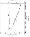
- Figure 1 is a chart representing a GPC chromatogram of a toner THF-soluble content.
- Figure 2 is a graph showing viscoelasticity characteristics of a magnetic black toner according to the invention.
- Figure 3 is a graph showing viscoelasticity characteristics of a comparative magnetic black toner.
- Figure 4 is an illustration of a system for practicing an embodiment of the multi-color or full-color image forming method according to the invention.
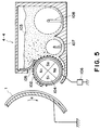
- Figure 5 is an illustration of a developing apparatus containing a magnetic black toner.
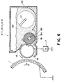
- Figure 6 is an illustration of a developing apparatus containing a non-magnetic color toner.
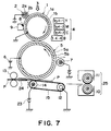
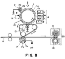
- Figures 7 and 8 are respectively an illustration of a system for practicing an embodiment of the multi-color or full-color image forming method according to the invention.
- Figure 9 is a graph showing a relationship between shape factors SF-1 and SF-2 of toners.
- Figure 10 is a sectional view of non-magnetic color toner particles.
- Figure 11 is a schematic partial sectional illustration of a photosensitive drum as an image bearing member.
- Figure 12 is a schematic illustration of a heat-pressure fixing device equipped with an oil applicator used in a conventional multi-color or full-color image forming apparatus.
- the binder resin of the magnetic black toner according to the present invention has a THF (tetrahydrofuran)-insoluble content of at most 5 wt. % and contains a THF-soluble content providing a GPC chromatogram showing a molecular weight distribution including a content (M1) at 40 - 70 % (areal percentage on the GPC chromatogram), of components having molecular weights of below 5x10 4 , a content (M2) at 20 - 45 % of components having molecular weights of 5x10 4 - 5x10 4 , and a content (M3) at 2 - 25 % of components having molecular weights exceeding 5x10 5 , satisfying M1 ⁇ M2 > M3.
- the content (M3) of the component having molecular weights exceeding 5x10 5 is below 2 %, the anti-high-temperature offset characteristic and the continuous image formation characteristic on a large number of sheets are lowered and, in excess of 25 %, the low-temperature fixability is lowered.
- the magnetic toner having a content (M2) at 25 - 45 % of the components having molecular weights of 5x10 4 - 50x10 4 and satisfying M1 ⁇ M2 > M3 allows easy control of gloss and can provide a high-quality fixed image having an appropriate degree of gloss, thus providing a broad fixable temperature range and an excellent image gloss in combination.
- the molecular weight distribution of the THF-soluble content of a binder resin may be determined based on a chromatogram obtained by gel permeation chromatography (GPC). More specifically, the GPC measurement may be performed by subjecting a sample toner to 20 hours of extraction with THF (tetrahydrofuran) solvent by means of a Soxhlet's extractor, and subjecting the resultant THF solution to GPC molecular weight-distribution measurement by using a succession of columns of A-801, 802, 803, 804, 805, 806 and 807 with reference to a calibration curve obtained based on standard polystyrene resin samples.
- GPC gel permeation chromatography
- the THF-soluble content of the binder resin may preferably provide a ratio Mw/Mn of 2 - 100 between weight-average molecular weight (Mw) and number-average molecular weight (Mn).
- the binder resin may preferably have an acid value of 2 - 30 mgKOH/g, more preferably 5 - 25 mgKOH/g, so as to provide improved charging stability and transferability to the resultant toner.
- the binder resin of the magnetic toner may preferably have a glass transition point (Tg) of 50 - 75 o C, more preferably 52 - 70 o C, in view of the fixability and storability.
- Tg glass transition point
- the glass transition point Tg of a binder resin may be determined based on a DSC curve obtained by using a high-accuracy internal heating input compensation-type differential scanning calorimeter (e.g., "DSC-7", available from Perkin-Elmer Corp.).
- DSC-7 high-accuracy internal heating input compensation-type differential scanning calorimeter
- the magnetic toner of the present invention is characterized by viscoelasticity characteristics including a value C of tan ⁇ at 100 o C and a value D of tan ⁇ at 150 o C giving a ratio D/C of at least 1.0, and a minimum (Emin) and a maximum (Emax) of tan ⁇ within a temperature range of 150 - 190 o C falling in a range of 0.5 - 3.0.
- D/C value, Emin and Emax within the above-described ranges, the resultant toner can provide a moderate image gloss over a broad fixable temperature range even in the oil-less fixation system and also satisfactory image formation performance on a large number of sheets.
- Emin and Emax are in the range of 1.0 - 2.0, the above-mentioned properties are further improved.
- the viscoelasticity values including tan ⁇ may be measured by using a viscoelasticity measurement apparatus (e.g., "Rheometer PDA-II", available from Rheometrics Co.) equipped with 25 mm-dia. parallel plates as shearing means at a measurement frequency of 6.28 radian/sec and a temperature-raising rate of 1 o C/min in a measurement temperature range of 80 o C to 200 o C.
- the magnetic toner according to the present invention contains a wax (first solid wax) which is solid at room temperature and provides a DSC curve showing a heat-absorption main-peak temperature of 60 - 120 o C, preferably 80 - 110 o C.
- first solid wax which is solid at room temperature and provides a DSC curve showing a heat-absorption main-peak temperature of 60 - 120 o C, preferably 80 - 110 o C.
- the wax fails to provide a heat-absorption main peak in the temperature range of 60 - 120 o C, good fixability characteristics as described above cannot be attained in the oil-less fixation system.
- the wax can also have a heat absorption sub-peak at a temperature above 120 o C. It is preferred to use a solid wax not showing a DSC heat-absorption sub-peak at a temperature below 60 o C.
- a solid wax showing a DSC heat-absorption sub-peak at a temperature below 60 o C is liable to result in a magnetic toner providing a lower image density and having lower storability.
- the magnetic black toner obtained by incorporating the wax having a DSC heat-absorption main peak in the range of 60 - 120 o C in the magnetic black toner particles also exhibits a DSC heat-absorption main peak in the range of 60 - 120 o C on its DSC curve.
- the solid wax used in the present invention has a very sharp molecular weight distribution as represented by a ratio Mw/Mn of 1.0 to 2.0 between the weight-average molecular weight (Mw) and number-average molecular weight (Mn) according to the GPC measurement.
- Mw weight-average molecular weight
- Mn number-average molecular weight
- the molecular weight distribution of a wax may be measured by gel permeation chromatography (GPC) according to the following conditions.
- the molecular weight distribution of a sample is obtained once based on a calibration curve prepared by monodisperse polystyrene standard samples, and recalculated into a distribution corresponding to that of polyethylene using a conversion formula based on the Mark-Houwink viscosity formula.
- the solid wax may preferably have a number-average molecular weight of 350 - 2000, more preferably 400 - 1000, in view of the dispersibility in the binder resin and in order to provide a magnetic black toner exhibiting good anti-low-temperature offset characteristic, anti-high-temperature offset characteristic, anti-blocking property, and continuous image formation performance on a large number of sheets.
- solid wax may include: low-molecular weight hydrocarbon wax consisting of carbon and hydrogen, long-chain alkyl alcohol wax having an OH group, long-chain alkyl carboxylic acid wax having a COOH group and ester wax.
- examples of the low-molecular weight hydrocarbon wax may include:
- the long-chain alkyl alcohol wax may comprise a mixture of long-chain alkyl alcohols having a number of carbon atoms in the range of 20 - 200.
- the long-chain alkylcarboxylic acid wax may comprise a mixture of long-chain alkylcarboxylic acids having a number of carbon atoms in the range of 20 - 200.
- ester wax may include: purified carnauba wax, purified candelilla wax, and wax consisting principally of ester compounds between long-chain alkyl alcohols having 15 - 45 carbon atoms and long-chain alkylcarboxylic acids having 15 - 45 carbon atoms. It is particularly preferred to use low-molecular weight polyethylene wax having a sharp molecular weight distribution in the magnetic black toner.
- the solid wax may preferably be used in 0.5 - 8 wt. parts, more preferably 1 - 8 wt. parts, per 100 wt. parts of the binder resin in the magnetic black toner, so as to provide good anti-low-temperature offset characteristic, anti-high-temperature offset characteristic and gloss characteristic.
- the DSC heat-absorption peak may be determined by using a differential scanning calorimeter ("DSC-7", available from Perkin-Elmer Corp.) according to ASTM D3418-82.
- DSC-7 differential scanning calorimeter
- a sample in an amount of 2 - 10 mg accurately weighed is placed on an aluminum pan and subjected to measurement in a temperature range of 30 - 160 o C at a temperature-raising rate of 10 o C/min. in a normal temperature - normal humidity environment in parallel with a blank aluminum pan as a reference.
- binder resin used in the magnetic black toner according to the present invention may include: polystyrene; homopolymers of styrene derivatives, such as poly-p-chlorostyrene and polyvinyltoluene; styrene copolymers, such as styrene-p-chlorostyrene copolymer, styrene-vinyltoluene copolymer, styrene-vinylnaphthalene copolymer, styrene-acrylate copolymer, styrene-methacrylate copolymer, styrene-methyl ⁇ -chloromethacrylate copolymer, styrene-acrylonitrile copolymer, styrene-vinyl methyl ether copolymer, styrene-vinyl ethyl ether copolymer, styrene-vinyren
- Comonomers constituting styrene copolymers may also include: monocarboxylic acids and derivatives thereof having a double bond, such as acrylic acid, methyl acrylate, ethyl acrylate, butyl acrylate, dodecyl acrylate, octyl acrylate, 2-ethylhexyl acrylate, phenyl acrylate, methacrylic acid, methyl methacrylate, ethyl methacrylate, butyl methacrylate, octyl methacrylate, acrylonitrile, methacrylonitrile, and acrylamide; and dicarboxylic acids and derivatives thereof having a double bond, such as maleic acid, butyl maleate, methyl maleate.
- monocarboxylic acids and derivatives thereof having a double bond such as acrylic acid, methyl acrylate, ethyl acrylate, butyl acrylate, dodecyl acrylate, oct
- the styrene copolymer may preferably be in the form of a crosslinked styrene copolymer having a THF-insoluble content of at most 5 wt. %, more preferably at most 3 wt. %, most preferably at most 1 wt. %.
- crosslinking agent may include: aromatic divinyl compounds, such as divinylbenzene and divinylnaphthalene; carboxylic acid esters having two double bonds, such as ethylene glycol diacrylate, ethylene glycol dimethacrylate, and 1,3-butanediol dimethacrylate; divinyl compounds, such as divinylaniline, divinyl ether, divinyl sulfide, and divinylsulfone; and compounds having three or more vinyl groups.
- aromatic divinyl compounds such as divinylbenzene and divinylnaphthalene
- carboxylic acid esters having two double bonds such as ethylene glycol diacrylate, ethylene glycol dimethacrylate, and 1,3-butanediol dimethacrylate
- divinyl compounds such as divinylaniline, divinyl ether, divinyl sulfide, and divinylsulfone
- compounds having three or more vinyl groups such as divinylaniline, divinyl
- the "THF-insoluble content" of a binder resin constituting toner particles referred to herein means a weight percentage of an ultra-high molecular weight polymer component (substantially, a crosslinked polymer) which is insoluble in a solvent THF (tetrahydrofuran) within the resin composition constituting a toner, and may be defined as a value measured in the following manner.
- a binder resin sample is weighed (at W 1 g) and placed in a cylindrical filter paper (e.g., "No. 86R" available from Toyo Roshi K.K.) and then subjected to extraction with 100 - 200 ml of solvent THF in a Soxhlet's extractor for 6 hours.
- the soluble content extracted with the solvent is dried first by evaporation of the solvent and then by vacuum drying at 100 o C for several hours, and weighed (at W 2 g).
- the THF-insoluble content (wt. %) of the binder resin is calculated as [(W 1 -W 2 )/W 1 ] x 100 .
- Such a THF-insoluble content and a molecular weight distribution of a binder resin measured for the binder resin as a starting material can be changed through a melt-kneading step for producing toner particles. In such a case, it is necessary to determine a THF-insoluble content and a molecular weight distribution of a binder resin constituting toner particles.
- the THF-insoluble content of a binder resin constituting toner particles can be recovered by subjecting a magnetic black toner to extraction with toluene in a Soxhlet's extractor to recover a toluene-soluble content and, after solidifying the extract, removing a THF-soluble content from the solidified extract.
- the THF-soluble content of a binder resin constituting toner particles may be determined in the following manner.
- a magnetic black toner sample is weighed (at W 3 g) and placed in a cylindrical filter paper (e.g., "No. 86R" available from Toyo Roshi K.K.) and then subjected to extraction with 100 - 200 ml of solvent THF in a Soxhlet's extractor for 6 hours.
- the soluble content extracted with the solvent is dried first by evaporation of the solvent and then by vacuum drying at 100 o C for several hours, and weighed (at W 4 g).
- the components other than the resin component, such as a magnetic material and pigment, are weighed or determined (at W 5 g) in advance.
- the THF-insoluble content (wt. %) is calculated as [(W 3 -(W 5 +W 4 ))/(W 3 -W 5 )] x 100 .
- the binder resin used in the present invention may for example be produced through solution polymerization in an organic solvent by adding dropwise (or continuously or batchwise) thereto a monomer mixture including styrene monomer, maleic acid half ester, divinylbenzene and one or two or more species of radical polymerization initiator having a 10-hour half-life temperature (temperature giving a half-life of 10 hours) of at least 100 o C.
- a binder resin having a prescribed molecular weight distribution and a THF-insoluble content of at most 5 wt. % can be prepared by adjusting the amount of the crosslinking agent such as divinylbenzene, the species and amount of the radical polymerization initiator, the addition rate of the monomer mixture, the polymerization temperature, etc.
- the acid value of a binder resin may be determined according to JIS K-0670 in the following manner.
- Acid value (mgKOH/g) KOH (ml) x N x 56.1/sample weight, wherein N denotes a factor of the N/10-caustic potash solution.
- the magnetic material may comprise a metal oxide containing one or more elements such as iron, cobalt, nickel, copper, magnesium, manganese, aluminum and silicon. Among theses, it is preferred to use a magnetic material principally comprising iron oxide, which can further contain silicon, aluminum or another metal element, in view of the chargeability control of the resultant magnetic black toner.
- the magnetic material may preferably have a BET specific surface area according to nitrogen adsorption of 2 - 30 m 2 /g, particularly 3 - 28 m 2 /g. It is further preferred to use a magnetic material having a Mohs hardness of 5 - 7.
- the magnetic material may preferably be in the form of particles having little shape anisotropy, e.g., having a shape of octahedral, hexahedral or sphere, in order to provide a high image density.
- the magnetic material may preferably have a number average particle size (diameter) of 0.05 - 1.0 ⁇ m, more preferably 0.1 - 0.6 ⁇ m, further preferably 0.1 - 0.4 ⁇ m.
- the magnetic material may be used in 30 - 200 wt. parts, preferably 50 - 150 wt. parts, per 100 wt. parts of the binder resin.
- the toner conveying force is liable to be lowered to result in a developer layer irregularity leading to an image irregularity when used in a developing apparatus utilizing a magnetic force for toner conveyance.
- the resultant magnetic black toner is liable to have an excessive triboelectric chargeability to result in a lowering of image density.
- excess of 200 wt. parts the resultant toner is liable to have a lower fixability, thus making it difficult to provide a fixed image with an increased gloss.
- the magnetic black toner particles may preferably have shape factors SF-1 and SF-2 satisfying the following conditions (1) - (3) in view of the continuous image forming performance, the transferability and cleanability:
- the shape factors SF-1 and SF-2 referred to herein are based on values measured in the following manner. Sample particles are observed through a field-emission scanning electron microscope ("FE-SEM S-800", available from Hitachi Seisakusho K.K.) at a magnification of 1000, and 100 images of toner particles having a particle size (diameter) of at least 2 ⁇ m are sampled at random.
- FE-SEM S-800 field-emission scanning electron microscope
- MXLNG denotes the maximum length of a sample particle
- PERIME denotes the perimeter of a sample particle
- AREA denotes the projection area of the sample particle.
- the shape factor SF-1 represents the roundness of toner particles
- the shape factor SF-2 represents the roughness of toner particles.
- the ratio B/A may preferably be 0.2 - 0.9, more preferably 0.35 - 0.85 so as to provide a better transferability while retaining the developing performance. Further, owing to the inorganic fine powder present on the surface of magnetic toner particles, the transferability can be further improved and the transfer drop-out (or hollow character) of character or line images can be better prevented.
- the magnetic toner particles may preferably have a weight-average particle size (diameter) of 4 - 8 ⁇ m. Toner particles having a weight-average particle size below 4 ⁇ m are liable to result in an increased amount of transfer residual toner on the photosensitive member or the intermediate transfer member and also liable to result in image ununiformity or irregularity due to fog and transfer failure. Toner particles having a weight-average particle size exceeding 8 ⁇ m are liable to cause scattering of character and line images.
- the average particle size and particle size distribution a toner may be measured according to various methods by using a Coulter counter Model TA-II or Coulter Multisizer (respectively available from Coulter Electronics Inc.) etc., but values described herein are based on results obtained by using a Coulter Multisizer to which an interface for outputting a number-basis distribution and a volume-basis distribution (available from Nikkaki K.K.) and a personal computer ("PC9801" available from NEC K.K.) are connected, together with a 1 %-NaCl aqueous solution as an electrolytic solution prepared by using a reagent-grade sodium chloride.
- a surfactant preferably an alkylbenzenesulfonic acid salt
- 2 to 20 mg of a sample is added thereto.
- the resultant dispersion of the sample in the electrolytic liquid is subjected to a dispersion treatment for about 1 - 3 minutes by means of an ultrasonic disperser, and then subjected to measurement of particle size distribution in the range of at least 2 ⁇ m by using the above-mentioned Coulter Multisizer with a 100 ⁇ m-aperture to obtain a volume-basis distribution and a number-basis distribution.
- the weight-average particle size (D 4 ) and the number-average particle size (D 1 ) may be obtained from the volume-basis distribution and the number-basis distribution, respectively.
- the magnetic black toner may preferably contain a charge control agent incorporated in (i.e., internally added to) toner particles or blended with (i.e., externally added to) toner particles.
- a charge control agent allows an optimum charge control for a particular developing system used, and particularly provides a further stabilized balance of particle size distribution and chargeability.
- negative charge control agents may include: organometal complexes or chelate compounds, such as monoazo metal complexes, acetylacetone metal complexes, and metal complexes of aromatic hydroxycarboxylic acids and aromatic dicarboxylic acids.
- organometal complexes or chelate compounds such as monoazo metal complexes, acetylacetone metal complexes, and metal complexes of aromatic hydroxycarboxylic acids and aromatic dicarboxylic acids.
- Other examples may include: aromatic hydroxycarboxylic acids, aromatic mono- and poly-carboxylic acids, and metal salts, anhydrides and esters of these, and phenol derivatives, such as bisphenols.
- positive charge control agents may include: nigrosine and products of modification thereof with aliphatic acid metal salts, etc.; onium salts including quaternary ammonium salts, such as tributylbenzylammonium-1-hydroxy-4-naphthosulfonate and tetrabutylammonium tetrafluoroborate, and homologues thereof, such as phosphonium salts, and lake pigments of these, triphenylmethane dyes and lake pigments thereof (with laking agents, such as phosphotungstic acid, phosphomolybdic acid, phosphotungsticmolybdic acid, tannic acid, lauric acid, gallic acid, ferricyanates, and ferrocyanates), higher aliphatic acid metal salts; diorganotin oxides, such as dibutyltin oxide, dioctyltin oxide, and dicyclohexyltin oxide; and diorganotin borates, such as dibutylt
- charge control agents may be used singly or in combination of two or more species.
- the charge control agent may preferably be fine powdery one. More specifically, the charge control agent may preferably have a number-average particle size of at most 4 ⁇ m, particularly at most 3 ⁇ m. In case of the internal addition to the toner, the charge control agent may preferably be added in 0.1 - 20 wt. parts, particularly 0.2 - 10 wt. parts.
- the first inorganic fine powder externally added to the magnetic black toner particles may comprise known ones, preferably selected from silica, alumina, titania and double or composite oxides of these in view of the charging stability, developing performance, flowability and storability.
- Silica is especially preferred.
- Silica may be either dry process silica (or fumed silica) produced by vapor phase oxidation of silicon halide or silicon alkoxide, or wet-process silica formed from alkoxide or water glass.
- the dry-process silica is preferred because of less silanol group on the surface of or within silica particles and less production residues, such as Na 2 O or SO 3 2- .
- another metal halide such as aluminum chloride or titanium chloride together with silica halide during the dry-process silica production, it is also possible to obtain composite fine powder of silica with another metal oxide.
- the first inorganic fine powder may preferably have a number-average primary particle size of at most 30 nm and a specific surface area of at least 30 m 2 /g, particularly 50 - 400 m 2 /g, as measured by the BET method according to nitrogen adsorption.
- the first inorganic fine powder may be used in 0.1 - 8 wt. parts, preferably 0.5 - 5 wt. parts, further preferably 1.0 - 3.0 wt. parts, per 100 wt. parts of the magnetic black toner particles.
- the number-average primary particle sizes of inorganic fine powder referred to herein are based on values measured by selecting 100 particles thereof having a particle size of at least 1 nm at random from electron microscopic photographs thereof (at a magnification of 10 5 times) to measure the longest diameters for the respective particles and take an average thereof.
- the specific surface area of the inorganic fine powder referred to herein are based on values measured by using an automatic gas adsorption measurement apparatus ("Autosorb 1", available from Yuasa Ionix K.K.) and nitrogen gas as an adsorbate according to the BET multi-point method.
- Autosorb 1 available from Yuasa Ionix K.K.
- nitrogen gas as an adsorbate according to the BET multi-point method.
- the first inorganic fine powder may preferably have been surface-treated with a treating agent, such as silicon varnish, various modified silicone varnish, silicone oil, various modified silicone oil, silane coupling agent, silane coupling agent having a functional group, other organosilicone compounds and organotitanium compounds.
- a treating agent such as silicon varnish, various modified silicone varnish, silicone oil, various modified silicone oil, silane coupling agent, silane coupling agent having a functional group, other organosilicone compounds and organotitanium compounds.
- silica fine powder treated with silicone oil as the first inorganic fine powder in order to provide the magnetic black toner with an improved anti-high-temperature offset characteristic in the oil-less fixing system.
- a spherical second inorganic fine powder or resin fine powder having a number-average-primary particle size exceeding 30 nm (and preferably also a specific surface area of below 50 m 2 /g), more preferably exceeding 50 nm (and also a specific surface area of below 30 m 2 /g) in addition to the first inorganic fine powder in order to further improve the transferability and the cleanability.
- a spherical second inorganic fine powder or resin fine powder having a number-average-primary particle size exceeding 30 nm (and preferably also a specific surface area of below 50 m 2 /g), more preferably exceeding 50 nm (and also a specific surface area of below 30 m 2 /g) in addition to the first inorganic fine powder in order to further improve the transferability and the cleanability.
- examples thereof may include: spherical silica particles, spherical polymethylsiloxane particles and spherical resin fine particles
- the second inorganic fine powder and resin fine powder may preferably have a sphericity ( ⁇ ) of at least 0.90, defined as a ratio of a minimum length of diameter to a maximum length of diameter of a sample particle as measured in the following manner.
- Sample fine powder particles are fixed on a collodion film held on copper mesh and photographed at a magnification of 1000 through an electron microscope ("H-700H", available from Hitachi Seisakusho K.K.) at an acceleration voltage of 100 kV. From the resultant photographs (at a magnification of 3000 including a printing magnification of 3), 100 particles are selected to provide an average of the sphericity ( ⁇ ) referred to herein.
- powdery lubricants such as teflon powder, zinc stearate powder and polyvinylidene fluoride powder
- abrasives such as cerium oxide powder, silicon carbide powder, and strontium titanate powder
- electroconductivity-imparting agents such as carbon black powder, zinc oxide powder and tin oxide powder.
- the magnetic black toner according to the present invention may be produced through known processes.
- the binder resin, the wax, the metal salt or metal complex, the magnetic material and optional charge control agent and other additives may be sufficiently blended by a blender, such as a Henschel mixer or a ball mill, and then melt-kneaded by a hot-kneading means, such as hot rollers, a kneader or an extruder to mutually solubilize the resin and wax and disperse the magnetic material therein to form a melt-kneaded product, which is, after solidification by cooling, subjected to pulverization, classification and surface treatment (sphering). Either one of the classification and the surface treatment may be performed preceding to the other.
- the classification may preferably be performed by using a multi-division classifier utilizing the Coanda effect in view of the production efficiency.
- the surface treatment may be effected by subjecting pulverized toner particles to dispersion and heating in a hot water bath, to heating in a hot gas stream, or to application of mechanical impact energy.
- the mechanical impact application may preferably be performed at a temperature around the glass transition point Tg of the toner particles (e.g., Tg ⁇ 10 o C) in view of agglomeration prevention and productivity.
- Tg glass transition point
- a temperature in a range of Tg ⁇ 5 o C is preferred so as to reduce surface pores with a radius of 10 nm or larger and allow the inorganic fine powder to effectively function to provide an improved transferability.
- the magnetic black toner thus-obtained may for example be introduced into a developing apparatus 4-4 shown in Figure 5 (which may be incorporated in an image forming apparatus as shown in Figure 4, 7 or 8), and used for developing a digital electrostatic latent image formed on an image bearing member 1.
- the developing apparatus shown in Figure 5 includes a magnetic black toner 103, a developing sleeve 102 formed of a on-magnetic metal, such as aluminum or stainless steel, a fixed magnet 104 enclosed within the developing sleeve, a first stirring bar 107 and a second stirring bar 108.
- the developing sleeve 102 can be surfaced with a resin layer containing electroconductive particles dispersed therein.
- the developing sleeve 102 may be supplied with a DC bias and an AC bias from a bias application means 106 to form an alternating electric field between the image bearing member 1 and the developing sleeve 102, under the action of which a digital electrostatic latent image on the image bearing member is developed with a layer of the magnetic black toner formed on the sleeve 102 according to the reversal development mode, thereby forming a magnetic black toner image on the image bearing member 1.
- the magnetic toner image formed on the image bearing member 1 may be transferred onto an intermediate transfer member 5 (or 13) as shown in Figure 4 or 7 (or 8), and then transferred from the intermediate transfer member 5 (or 13) to a transfer-receiving material 6 (or P), or may be transferred from the image bearing member 1 directly to such a transfer-receiving material.
- the magnetic black toner according to the present invention as a black toner functioning as a contrast intensifier in multi-layer or full-color image formation according to the mono-component development mode, it becomes possible to provide a compact developing apparatus (as shown in Figure 4, 7 or 8) and also provide a black image with an improved image quality. Further, having excellent anti-offset characteristic and gloss characteristic, the magnetic black toner according to the present invention can provide a multi-color or full-color image even by the oil-less fixing system.
- non-magnetic color toner including a non-magnetic yellow toner, a non-magnetic magenta toner, and a non-magnetic cyan toner used in connection with the magnetic black toner according to the present invention.
- Each non-magnetic color toner may preferably contain 5 - 40 wt. parts, particularly 12 - 35 wt. parts of a low-softening point substance (preferably a solid wax) having DSC heat-absorption main peak at a temperature in the range of 60 - 120 o C per 100 wt. parts of the binder resin in order to exhibit good color mixability and anti-offset characteristic in the oil-less fixing system.
- a low-softening point substance preferably a solid wax
- the non-magnetic color toner particles may preferably be produced through a process wherein a polymerizable mixture is formed by adding to a polymerizable monomer an appropriate crosslinking agent and/or a resin component, a low-softening point substance and a polymerization initiator, dispersing the polymerizable mixture into droplets in an aqueous medium and polymerizing the droplets in the aqueous medium to form toner particles having an island/sea structure (including a core/shell structure) as shown in Figure 10, wherein the low-softening substance is enclosed within an outer shell binder resin comprising the polymerizate in each toner particle.
- Such an island/sea structure comprising a low-softening point substance with an outer shell binder resin may be formed, e.g., by a method of using a low-softening point substance having a small polarity than the principal monomer component together with a small amount of a resin or a monomer component having a larger polarity to form such a polymerizabie mixture, and polymerizing droplets of the polymerizable mixture to form non-magnetic color toner particles having a core/shell structure wherein the low-softening point substance is coated with the binder resin.
- the polymerizate particles thus formed may be used as they are as non-magnetic color toner particles or polymerizate particles produced in a very fine particle size may be agglomerated up to a desired particle size to form toner particles having a multi-island/sea structure (or a multi-core/shell structure).
- at least one species of the low-softening point substance has a melting point (a DSC maximum heat-absorption peak temperature) that is lower than the polymerization temperature.
- each toner particle By enclosing the low-softening point substance within the non-magnetic color toner particles, each toner particle is allowed to contain a relatively large amount of low-softening point substance while suppressing a lowering of anti-blocking property of the color toner, and is allowed to form a non-magnetic color toner particle having a good impact resistance, and good low-temperature fixability and color mixability in hot-pressure fixation by using a low-softening point substance of sharp-melting characteristic.
- the polymerizable monomer for providing a non-magnetic color toner through such a polymerization process may be a radially polymerizable vinyl-type monomer which may be either a monofunctional polymerizable monomer or a polyfunctional polymerizable monomer.
- Examples of the monofunctional polymerizable monomer may include: styrene and its derivatives, such as styrene, ⁇ -methylstyrene, ⁇ -methylstyrene, o-methylstyrene, m-methylstyrene, p-methylstyrene, 2,4-dimethylstyrene, p-n-hexylstyrene, p-tert-butylstyrene, p-n-hexylstyrene, p-n-octylstyrene, p-n-nonylstyrene, p-n-decylstyrene, p-n-dodecylstyrene, p-methoxystyrene, and p-phenylstyrene; acrylic polymerizable monomers, such as methyl acrylate, ethyl acrylate,
- polyfunctional polymerizable monomer may include: diethylene glycol diacrylate, triethylene glycol diacrylate, tetraethylene glycol diacrylate, polyethylene glycol diacrylate, 1,6-hexanediol diacrylate, neopentyl glycol diacrylate, tripropylene glycol diacrylate, polypropylene glycol diacrylate, 2,2'-bis[4-(acryloxy-diethoxy)phenyl]propane, trimethylpropane triacrylate, tetramethylolmethane tetraacrylate, ethylene glycol dimethacrylate, diethylene glycol dimethacrylate, triethylene glycol dimethacrylate, tetraethylene glycol dimethacrylate, polyethylene glycol dimethacrylate, 1,3-butylene glycol dimethacrylate, 1,6-hexanediol dimethacrylate, neopentyl glycol dimethacrylate, polypropylene glycol dimeth
- the above-mentioned monofunctional polymerizable monomers may be used singly or in combination of two or more species thereof, or further in combination with one or more species of the polyfunctional polymerizable monomers, which can also function as a crosslinking agent.
- the polymerization initiator used for polymerization of the above-mentioned polymerizable monomer may be an oil-soluble initiator and/or a water-soluble initiator.
- the oil-soluble initiator may include: azo compounds, such as 2,2'-azobisisobutyronitrile, 2,2'-azobis-2,4-dimethylvaleronitrile, 1,1'-azobis(cyclohexane-1-carbonitrile), and 2,2'-azobis-4-methoxy-2,4-dimethylvaleronitrile; and peroxide initiators, such as acetylcyclohexylsulfonyl peroxide, diisopropyl peroxycarbonate, decanoyl peroxide, lauroyl peroxide, stearoyl peroxide, propionyl peroxide, acetyl peroxide, t-butyl peroxy-2-ethylhexanoate, benzoyl peroxide, t-but
- water-soluble initiator may include: ammonium persulfate, potassium persulfate, 2,2'-azobis(N,N'-dimethyleneisobutyroamidine) hydrochloric acid salt, 2,2'-azobis(2-amidinopropane) hydrochloric acid salt, azobis(isobutylamidine) hydrochloric acid salt, sodium 2,2'-azobisisobutyronitrilesulfonate, ferrous sulfate and hydrogen peroxide.
- the toner according to the present invention may particularly preferably be produced through the suspension polymerization process by which a particulate toner having a small particle size of 4 - 8 ⁇ m can be easily produced with a uniformly controlled shape and a sharp particle size distribution. It is also possible to suitably apply the seed polymerization process wherein once-obtained polymerizate particles are caused to adsorb a monomer, which is further polymerized in the presence of a polymerization initiator. It is also possible to include a polar compound in the monomer adsorbed by dispersion or dissolution.
- toner particles may be produced directly in the following manner.
- a low-softening point substance such as wax, a colorant, a polymerization initiator, a polar polymer such as a polyester, a crosslinking agent and another optional additive are added and uniformly dissolved or dispersed by a homogenizer or an ultrasonic dispersing device, to form a polymerizable monomer composition, which is then dispersed and formed into particles in a dispersion medium containing a dispersion stabilizer by means of an ordinary stirrer, a homomixer or a homogenizer preferably under such a condition that droplets of the polymerizable monomer composition can have a desired particle size of the resultant color toner particles by controlling stirring speed and/or stirring time.
- the stirring may be continued in such a degree as to retain the particles of the polymerizable monomer composition thus formed and prevent the sedimentation of the particles.
- the polymerization may be performed at a temperature of at least 40 o C, generally 50 - 90 o C, preferably 55 - 85 o C. The temperature can be raised at a later stage of the polymerization. It is also possible to subject a part of the aqueous system to distillation in a latter stage of or after the polymerization in order to remove the yet-unpolymerized part of the polymerizable monomer and a by-product which can cause an odor in the toner fixation step. After the reaction, the produced color toner particles are washed, filtered out, and dried. In the suspension polymerization, it is generally preferred to use 300 - 3000 wt. parts of water as the dispersion medium per 100 wt. parts of the monomer composition.
- an inorganic or/and an organic dispersion stabilizer in an aqueous dispersion medium.
- the inorganic dispersion stabilizer may include: tricalcium phosphate, magnesium phosphate, aluminum phosphate, zinc phosphate, calcium carbonate, magnesium carbonate, calcium hydroxide, magnesium hydroxide, aluminum hydroxide, calcium metasilicate, calcium sulfate, barium sulfate, bentonite, silica, and alumina.
- organic dispersion stabilizer may include: polyvinyl alcohol, gelatin, methyl cellulose, methyl hydroxypropyl cellulose, ethyl cellulose, carboxymethyl cellulose sodium salt, and starch. These dispersion stabilizers may preferably be used in the aqueous dispersion medium in an amount of 0.2 - 2.0 wt. parts per 100 wt. parts of the polymerizable monomer mixture.
- an inorganic dispersion stabilizer a commercially available product can be used as it is, but it is also possible to form the stabilizer in situ in the dispersion medium so as to obtain fine particles thereof.
- tricalcium phosphate for example, it is adequate to blend an aqueous sodium phosphate solution and an aqueous calcium chloride solution under an intensive stirring to produce tricalcium phosphate particles in the aqueous medium, suitable for suspension polymerization.
- Examples of the surfactant may include: sodium dodecylbenzenesulfonate, sodium tetradecyl sulfate, sodium pentadecyl sulfate, sodium octyl sulfate, sodium oleate, sodium laurate, potassium stearate, and calcium oleate.
- Each non-magnetic color toner may preferably have a shape factor SF-1 of 100 - 160, more preferably 100 - 150, further preferably 100 - 125.
- the THF-soluble content of the binder resin may preferably have a molecular weight distribution according to gel permeation chromatography providing a main peak in a molecular weight region of 3x10 3 - 5x10 4 and a sub-peak or shoulder in a molecular weight region of at least 10 5 . It is further preferred to provide at least two in total of shoulder(s) and/or sub-peak(s) in the molecular weight region of at least 10 5 .
- the binder resin principally comprising a styrene copolymer may preferably contain a THF-insoluble content in an amount of 0.1 - 20 wt. %, more preferably 1 - 15 wt. %, so as to provide a good balance of gloss with the above-mentioned magnetic black toner.
- a binder resin comprising a mixture of a styrene copolymer and a polyester resin.
- a binder resin comprising a mixture of a styrene copolymer and a polyester resin.
- a combination of a crosslinked styrene copolymer and a non-crosslinked polyester resin, or a combination of a crosslinked styrene copolymer and a crosslinked polyester resin so as to provide a non-magnetic color toner having good fixability, anti-offset characteristic and color mixability.
- a polyester resin is excellent in fixability and transparency and is suitable for providing a color toner requiring a good color mixability. It is particularly preferred to use a crosslinked or non-crosslinked polyester resin formed by polycondensation of a bisphenol derivative of the following formula: wherein R denotes an ethylene or propylene group, x and y are independently an integer of at least 1 with the proviso that the average of x+y is in the range of 2 - 10, or a substitution derivative thereof, as a diol component, with a carboxylic acid component selected from polycarboxylic acids having at least two carboxylic groups and their anhydrides and lower alkyl esters, such as fumaric acid, maleic acid, maleic anhydride, phthalic acid, terephthalic acid, trimellitic acid and pyromellitic acid.
- the polyester resin may preferably have an acid value of 1 - 35 mgKOH/g, more preferably 1 - 20 mgKOH/g, further preferably 3 - 15 mgKOH/g so as to provide a toner showing stable chargeability in various environmental conditions.
- the non-magnetic color toners may be prepared by using a yellow colorant, a magenta colorant and a cyan colorant, as described below, together with a binder resin as described above.
- yellow colorant may include: condensed azo compounds, isoindolinone compounds, anthraquinone compounds, azo metal complexes, methin compounds and acrylamide compounds. Specific preferred examples thereof may include C.I. Pigment Yellow 12, 13, 14, 15, 17, 62, 74, 83, 93, 94, 95, 97, 109, 110, 111, 120, 127, 128, 129, 147, 168, 174, 176, 180, 181 and 191.
- magenta colorant may include: condensed azo compounds, diketopyrrolepyrrole compounds, anthraquinone compounds, quinacridone compounds, basic dye lake compounds, naphthol compounds, benzimidazole compounds, thioindigo compounds and perylene compounds. Specific preferred examples thereof may include: C.I. Pigment Red 2, 3, 5, 6, 7, 23, 48:2, 48:3, 48:4, 57:1, 81:1, 144, 146, 166, 169, 177, 184, 185, 202, 206, 220, 221 and 254.
- cyan colorant may include: copper phthalocyanine compounds and their derivatives, anthraquinone compounds and basic dye lake compounds. Specific preferred examples thereof may include: C.I. Pigment Blue 1, 7, 15, 15:1, 15:2, 15:3, 15:4, 60, 62, and 66.
- chromatic colorants may be used singly, in mixture of two or more species or in a state of solid solution.
- the above colorants may be appropriately selected in view of hue, color saturation, color value, weather resistance, OHP transparency, and a dispersibility in toner particles.
- These chromatic colorants may preferably be used in a proportion of 1 - 20 wt. parts per 100 wt. parts of the binder resin.
- the low-softening point substance used for constitutes a non-magnetic color toner may comprise a solid wax similar to the one used in the magnetic black toner.
- the low-softening substance for providing a non-magnetic color toner it is preferred to use a solid wax providing a DSC heat-absorption curve showing a heat-absorption main peak in a temperature range of 60 - 90 o C, more preferably 60 - 85 o C. It is further preferred to use a solid wax of a sharp melting characteristic as represented by a heat-absorption main giving a half-value width of at most 10 o C, more preferably at most 5 o C. It is particularly preferred to use an ester wax principally comprising ester compounds formed from long-chain alkyl alcohol(s) having 15 - 45 carbon atoms and long-chain alkylcarboxylic acid(s) having 15 - 45 carbon atoms.
- developing apparatus 4-1, 4-2, 4-3 and 4-4 are caused to contain a developer comprising a yellow toner, a developer comprising a magenta toner, a developer comprising a cyan toner, and a developer comprising a magnetic black toner, respectively, so as to develop electrostatic latent images formed on a photosensitive member 1 as an image bearing member according to a non-magnetic mono-component developing scheme or a magnetic jumping developing scheme, thereby sequentially forming respective color toner images on the photosensitive member.
- the photosensitive member 1 may be in the form of a photosensitive drum as shown (or a photosensitive belt (not shown)) having an insulating photoconductor layer 1b comprising, e.g., amorphous selenium, cadmium sulfide, zinc oxide, organic photoconductor or amorphous silicon formed on an electroconductive substrate 1a.
- the photosensitive member 1 is rotated in an indicated arrow direction by a drive means (not shown).
- the photosensitive member 1 may preferably comprise an amorphous silicon photosensitive layer or OPC photosensitive layer.
- the organic photosensitive layer may be composed of a single layer comprising a charge-generating substance and a charge-transporting substance or may be function-separation type photosensitive layer comprising a charge generation layer and a charge transport layer.
- the function-separation type photosensitive layer may preferably comprise an electroconductive support, a charge generation layer, and a charge transport layer arranged in this order.
- the organic photosensitive layer may preferably comprise a binder resin, such as polycarbonate resin, polyester resin or acrylic resin, because such a binder resin is effective in providing an improved cleaning characteristic and is not liable to cause melt-sticking or filming of toner onto the photosensitive member.
- a binder resin such as polycarbonate resin, polyester resin or acrylic resin
- a charging step may be performed by using a corona charger which is not in contact with the photosensitive member 1 or by using a contact charger, such as a charging roller.
- the contact charging as shown in Figure 4 may preferably be used in view of efficiency of uniform charging, simplicity and a lower ozone-generating characteristic.
- the charging roller 2 comprises a core metal 2b and an electroconductive elastic layer 2a surrounding a periphery of the core metal 2b.
- the charging roller 2 is pressed against the photosensitive member 1 at a prescribed pressure (pressing force) and rotated mating with the rotation of the photosensitive member 1.
- the charging step using the charging roller may preferably be performed under process conditions including an applied pressure of the roller of 5 - 500 g/cm, an AC voltage of 0.5 - 5 kVpp, an AC frequency of 50 - 5 kHz and a DC voltage of ⁇ 0.2 - ⁇ 5 kV in the case of applying AC voltage and DC voltage in superposition.
- the charging roller and charging blade each used as a contact charging means may preferably comprise an electroconductive rubber and may optionally comprise a releasing film on the surface thereof.
- the releasing film may comprise, e.g., a nylon-based resin, polyvinylidene fluoride (PVDF), polyvinylidene chloride (PVDC) or fluorinated acrylic resin.
- a toner image formed on the photosensitive member 1 may be transferred onto a drum-shaped intermediate transfer member 5 supplied with a transfer voltage of, e.g., ⁇ 0.1 - ⁇ 5 kV (or a belt-shaped intermediate transfer member 13 supplied with a transfer bias voltage from a bias means 13a as shown in Figure 8).
- the intermediate transfer member 5 comprises a pipe-like electroconductive core metal 5b and a medium resistance-elastic layer 5a (e.g., an elastic roller) surrounding a periphery of the core metal 5b.
- the core metal 5b can also comprise a plastic pipe coated by electroconductive plating.
- the medium resistance-elastic layer 5a may be a solid layer or a foamed material layer in which an electroconductivity-imparting substance, such as carbon black, zinc oxide, tin oxide or silicon carbide, is mixed and dispersed in an elastic material, such as silicone rubber, teflon rubber, chloroprene rubber, urethane rubber or ethylene-propylene-diene terpolymer (EPDM), so as to control an electric resistance or a volume resistivity at a medium resistance level of 10 5 - 10 11 ohm.cm.
- an electroconductivity-imparting substance such as carbon black, zinc oxide, tin oxide or silicon carbide
- the intermediate transfer member 5 is born on a shaft parallel to the photosensitive member 1 and disposed in contact with a lower surface port of the photosensitive member 1 so as to be rotatable in a counterclockwise direction indicated by an arrow at an identical peripheral speed as the photosensitive member 1.
- a transfer roller 7 as a transfer means is supported on a shaft parallel to the intermediate transfer member 5 and disposed contactable to a lower surface of the intermediate transfer member 5.
- the transfer roller 7 is rotated in a clockwise direction indicated by an arrow.
- the transfer roller 7 may be disposed contactable to the intermediate transfer member 5 directly as shown in Figure 5 or via a transfer belt 12 as shown in Figure 7.
- the transfer roller basically comprises a core metal 7b and an electroconductive elastic layer 7a covering the outer periphery of the core metal 7b.
- the intermediate transfer member and transfer means can comprise an ordinary material. If the transfer means is set to have a lower volume resistivity than the intermediate transfer member, the application voltage to the transfer means can be alleviated, whereby a good toner image can be formed on the transfer-receiving material and the winding of the transfer-receiving material about the intermediate transfer member can be prevented. It is particularly preferred that the elastic layer of the intermediate transfer member has a volume resistivity at least ten times that of the elastic layer of the transfer means.
- the hardness of the elastic layers of the intermediate transfer member and the transfer means may be determined according to JIS K-6301. More specifically, the intermediate transfer member may preferably comprise an elastic layer having a hardness in the range of 10 - 40 deg. On the other hand, the transfer means may preferably comprise an elastic layer having a hardness of 41 - 80 deg. representing a higher hardness than that of the intermediate transfer member, so as to prevent the wining of a transfer-receiving material about the intermediate transfer member. If the intermediate transfer member is softer than the transfer means, a recess may be formed preferentially on the side of the intermediate transfer member, whereby the winding of the transfer-receiving material onto the intermediate transfer member can be prevented.
- the transfer roller 7 may be rotated at a peripheral speed identical to or different from that of the intermediate transfer member 5.
- a bias voltage of a polarity opposite to that of the triboelectric charge of the toner image is applied to the transfer roller to transfer the toner image on the intermediate transfer member 5 onto the surface of the transfer-receiving material 6.
- the transfer roller 7 may comprise a similar material as the charging roller 2. More specifically, the transfer roller 7 may have an electroconductive elastic layer 7a which is a solid or foamed layer comprising an elastic material such as polyurethane rubber or EPDM containing an electroconductivity-imparting agent such as carbon black, zinc oxide or silicon carbide to provide a medium level of volume resistivity on the order of 10 6 - 10 10 ohm.cm.
- an electroconductive elastic layer 7a which is a solid or foamed layer comprising an elastic material such as polyurethane rubber or EPDM containing an electroconductivity-imparting agent such as carbon black, zinc oxide or silicon carbide to provide a medium level of volume resistivity on the order of 10 6 - 10 10 ohm.cm.
- Preferred transfer process conditions may include: a transfer roller abutting pressure of 2.94 - 490 N/m (3 - 500 g/cm), more preferably 19.6 - 294 N/m and a DC voltage of ⁇ 0.2 - ⁇ 10 kV.
- a transfer roller abutting pressure of 2.94 - 490 N/m (3 - 500 g/cm)
- more preferably 19.6 - 294 N/m and a DC voltage of ⁇ 0.2 - ⁇ 10 kV.
- the transfer-receiving material 6 carrying the transferred toner image is conveyed to an oil-less fixing device 25 comprising basically a heating roller 11 containing therein a heat-generating member such as a halogen heater but not equipped with an oil applicator and an elastic pressure roller 10 pressed against the heating roller and the toner image is fixed onto the transfer-receiving material 6 while being passed through the heating roller an the pressure roller.
- an oil-less fixing device 25 comprising basically a heating roller 11 containing therein a heat-generating member such as a halogen heater but not equipped with an oil applicator and an elastic pressure roller 10 pressed against the heating roller and the toner image is fixed onto the transfer-receiving material 6 while being passed through the heating roller an the pressure roller.
- the development an multi-color or full-color image formation on the photosensitive member (image bearing member) 1 may be performed in the following manner.
- the photosensitive member 1 is uniformly charged to prescribed polarity and potential by the primary charging roller 2 and then exposed to image light 3 from an unshown imagewise exposure means (e.g., a system for color separation of a color original image and focusing exposure, or a scanning exposure system including a laser scanner for outputting a laser beam modified corresponding to time-serial electrical digital image signals based on image data) to form an electrostatic latent image corresponding to a first color component image (e.g., yellow image) of the objective color image.
- an unshown imagewise exposure means e.g., a system for color separation of a color original image and focusing exposure, or a scanning exposure system including a laser scanner for outputting a laser beam modified corresponding to time-serial electrical digital image signals based on image data
- a first color component image e.g., yellow image
- the developing device 4-1 constitutes an apparatus unit which is detachably mountable to a main assembly of the image forming apparatus, and an enlarged view thereof is shown in Figure 6.
- the developing device 4-1 includes an outer wall or casing 22 enclosing a mono-component non-magnetic yellow toner 20. Being half enclosed within the outer wall 22, a developing sleeve 16 (as a toner-carrying member) is disposed opposite to the photosensitive member 1 rotating in an indicated arrow a direction and so as to develop the electrostatic image on the photosensitive member 1 with the toner carried thereon, thereby forming a toner image on the photosensitive member 1.
- a right half of the developing sleeve 16 is protruded and enclosed in the outer wall 22 and a left half thereof is exposed out of the outer wall 22 and disposed in a lateral position with the photosensitive member 1 and so as to be movable in an indicated arrow b direction while facing the photosensitive member 1.
- a small gap is left between the developing sleeve 16 and the photosensitive member 1.
- the toner-carrying member need not be in a cylindrical form like the developing sleeve 16, but can be in an endless belt form driven in rotation or composed of an electroconductive rubber roller.
- an elastic blade 19 (as an elastic regulation member) is disposed above the developing sleeve 16, and a toner application roller 18 is disposed upstream of the elastic blade 19 in the rotation direction of the developing sleeve 16.
- the elastic regulation member can also be an elastic roller.
- the elastic blade 19 is disposed with a downward inclination toward the upstream side of the rotation direction of the developing sleeve, and abutted counterdirectionally against an upper rotating peripheral surface of the developing sleeve.
- the toner application roller 18 is abutted rotatably against a side of the developing sleeve 16 opposite to the photosensitive member 1.
- the toner application roller 18 is rotated in an arrow c direction to supply the yellow toner 20 to the vicinity of the developing sleeve 16 and, at an abutting position (nip position) with the developing sleeve 16, frictionally applies or attaches the yellow toner 20 onto the developing sleeve 16.
- the yellow toner 20 attached to the developing sleeve 16 is caused to pass between the elastic blade 19 and the developing sleeve 16 at their abutting position, where the toner is rubbed with the surfaces of both the developing sleeve 16 and the elastic blade 19 to be provided with a sufficient triboelectric charge.
- the thus triboelectrically charged yellow toner 20 having passed through the abutting position between the developing sleeve 16 and the elastic blade 19 forms a thin layer of yellow toner to be conveyed to a developing position facing the photosensitive member 1.
- the developing sleeve 16 is supplied with a DC-superposed AC bias voltage by a bias application means 17, whereby the yellow toner 20 on the developing sleeve is transferred and attached onto the electrostatic image on the photosensitive member 1, to form a toner image.
- a portion of the yellow toner 20 remaining on the developing sleeve 16 without being transferred onto the photosensitive member 1 at the developing position is recovered into the outer wall 22 while passing below the developing sleeve 16 along with the rotation of the developing sleeve 16.
- the recovered yellow toner 20 is peeled apart from the developing sleeve 16 by the toner application roller 18 at the abutting position with the developing sleeve 16. Simultaneously therewith, a fresh yellow toner 20 is supplied to the developing sleeve 16 by the rotation of the toner application roller 18, and the fresh yellow toner 20 is again moved to the abutting position between the developing sleeve and the elastic blade 19.
- a non-magnetic color toner prepared in a manner as described above can exhibit good developing performance and continuous image forming characteristic in the above-described non-magnetic mono-component developing step.
- the developing sleeve 16 may preferably comprise an electroconductive cylinder of a metal or alloy, such as aluminum or stainless steel, but can be composed of an electroconductive cylinder formed of a resin composition having sufficient mechanical strength and electroconductivity.
- the developing sleeve 16 may comprise a cylinder of a metal or alloy surface-coated with a coating layer of a resin composition containing electroconductive fine particles dispersed therein.
- the electroconductive particles may preferably exhibit a volume resistivity of at most 0.5 ohm.cm after compression at 120 kg/cm 2 .
- the electroconductive fine particles may preferably comprise carbon fine particles, a mixture of carbon fine particles and crystalline graphite powder, or crystalline graphite powder.
- the electroconductive fine particles may preferably have a particle size of 0.005 - 10 ⁇ m.
- Example of the resin material constituting the resin composition may include: thermoplastic resins, such as styrene resin, vinyl resin, polyethersulfone resin, polycarbonate resin, polyphenylene oxide resin, polyamide resin, fluorine-containing resin, cellulosic resin, and acrylic resin; and thermosetting or photocurable resins, such as epoxy resin, polyester resin, alkyd resin, phenolic resin, melamine resin, polyurethane resin, urea resin, silicone resin, and polyimide resin.
- thermoplastic resins such as styrene resin, vinyl resin, polyethersulfone resin, polycarbonate resin, polyphenylene oxide resin, polyamide resin, fluorine-containing resin, cellulosic resin, and acrylic resin
- thermosetting or photocurable resins such as epoxy resin, polyester resin, alkyd resin, phenolic resin, melamine resin, polyurethane resin, urea resin, silicone resin, and polyimide resin.
- a resin showing a releasability such as silicone resin or fluorine-containing resin; or a resin showing excellent mechanical properties, such as polyethersulfone, polycarbonate, polyphenylene oxide, polyamide, phenolic resin, polyester, polyurethane or styrene resin. Phenolic resin is particularly preferred.
- the electroconductive fine particles may preferably be used in 3 - 20 wt. parts per 100 wt. parts of the resin component.
- the electroconductive particle-dispersed resin coating layer of the sleeve may preferably show a volume resistivity of 10 -6 - 10 6 ohm.cm.
- the image forming apparatus shown in Figure 4 further includes a magenta developing device 4-2 and a cyan developing device 4-3 each of which may be a non-magnetic mono-component developing device having a structure similar to that of the yellow developing device 4-1 described above with reference to Figure 6, and after these non-magnetic mono-component developing devices 4-1, 4-2 and 4-3, a magnetic black developing device described with reference to Figure 5 is placed for black development according to the magnetic mono-component development mode.
- a magenta developing device 4-2 and a cyan developing device 4-3 each of which may be a non-magnetic mono-component developing device having a structure similar to that of the yellow developing device 4-1 described above with reference to Figure 6, and after these non-magnetic mono-component developing devices 4-1, 4-2 and 4-3, a magnetic black developing device described with reference to Figure 5 is placed for black development according to the magnetic mono-component development mode.
- Figure 7 illustrates another multi-color or full-color image forming apparatus, wherein a transfer belt 15 is used as a secondary transfer means.
- the transfer belt 17 is supported about a shaft parallel to a rotation axis of the intermediate transfer member so as to be in contact with a lower surface of the intermediate transfer member 5.
- the transfer belt 15 is supported about a bias roller 14 and a tension roller 17.
- the bias roller 14 is supplied with a desired secondary transfer bias voltage from a secondary transfer voltage supply 23, and the tension roller 12 is grounded.
- a primary transfer bias voltage for superpositive transfer of first to fourth color toner images from the photosensitive member 1 to the intermediate transfer member 5 is of a polarity (+ in this embodiment) opposite to that of the toner and is supplied from a bias supply 6 to the intermediate transfer member 5.
- the transfer belt 10 For transfer of the superposedly transferred color toner images on the intermediate transfer member 5 to a transfer-receiving material P, the transfer belt 10 is abutted against the intermediate transfer member 5, a transfer-receiving material P is supplied from a paper supply cassette (not shown) via a register roller 13 and a transfer pre-guide 24 to a nip between the intermediate transfer member and the transfer belt 15 at a prescribed time, and simultaneously a secondary transfer bias voltage is supplied to the bias roller 14 from the bias supply 23. Under the action of the transfer bias voltage, the color toner image may be transferred from the intermediate transfer member 5 to the transfer-receiving material P. This step may be called secondary transfer.
- Figure 8 illustrates still another multi-color or full-color image forming apparatus, wherein a transfer belt 13 equipped with a bias-application means 13a is used as an intermediate transfer means.
- the respective toners and the process conditions may preferably be set to provide a fixed solid image of the magnetic black toner and the fixed solid images of the respective non-magnetic color toners both showing a gloss value in the range of 5 - 30, more preferably 10 - 25, and providing a gloss value difference therebetween of at most 5, so as to provide a good quality of full-color images.
- the image bearing member (photosensitive member) 1 used in the present invention may preferably have a surface exhibiting a contact angle with water of at least 8 deg., more preferably at least 90 deg. If the contact angle with water is 85 deg. or larger, the toner image transferability may be increased and the toner filming is less liable to occur.
- the image forming method according to the present invention is particularly effective in case where the surface of the image bearing member 1 principally comprises a polymeric material or binder.
- This may include the case where an inorganic photosensitive layer of, e.g., selenium or amorphous silicon is coated with a protective film principally comprising a resin; the case of using a function separation-type organic photoconductor layer including a surface layer comprising a charge transport substance and a resin; and the use of using such an organic photoconductor layer further coated with a resinous protective film as described above.
- Such a surface layer may be provided with a releasability so as to provide an increased contact angle with water, e.g., by (1) using a resin having a low surface energy for constituting the layer, (2) incorporating an additive imparting water-repellency or lipophillicity and (3) dispersing a powder of a material exhibiting high releasability.
- the measure (1) may be effected by introducing a fluorine-containing group or a silicon-containing group into the resin.
- the measure (2) may be effected by adding a surfactant, etc.
- the measure (3) may be effected by using powder of fluorine-containing compound, such as polytetrafluoroethylene, polyvinylidene fluoride, or fluorinated carbon. Among these, polytetrafluoroethylene is most suited. In the present invention, it is particularly suited to disperse a powder of a releasable material, such as a fluorine-containing resin according to the measure (3).
- the incorporation of such a powder at the surface may be performed by forming anew a surface layer comprising such a powder dispersed within a binder resin onto the surface most layer of an organic photoconductive layer comprising principally a resin without forming anew such a surface layer.
- the powder may be added in 1 - 60 wt. %, preferably 2 - 50 wt. %, of the total weight of the surface layer. Below 1 wt. %, the improvement effect is scarce and, above 60 wt. %, the resultant film is caused to have a lower strength or reduce the quantity of light incident to the image bearing member.
- the above technique is particularly effective in the case of using a contact charging method wherein a charging member is directly abutted against the image bearing member in comparison with a corona charging method wherein the charging means does not directly contact the image bearing member. This is because the improvement in life can be remarkable in the former case wherein a larger load is applied to the image bearing member surface.
- Figure 11 is a preferred embodiment of such an image bearing member, i.e., one having a laminate structure successively including an (electroconductive) substrate 110, an optional electroconductive coating layer 111, an undercoating layer 112, a charge generation layer 113 and a charge transport layer 114.
- an image bearing member i.e., one having a laminate structure successively including an (electroconductive) substrate 110, an optional electroconductive coating layer 111, an undercoating layer 112, a charge generation layer 113 and a charge transport layer 114.
- the organization of the respective layers will be described below in further detail.
- the electroconductive support 110 may comprise a metal, such as aluminum or stainless steel, a plastic coated with a layer of aluminum alloy or indium oxide-tin oxide alloy, paper or a plastic sheet impregnated with electroconductive particles, or a plastic comprising an electroconductive polymer in a shape of a cylinder or a sheet.
- the undercoating layer 112 may comprise polyvinyl alcohol, poly-N-vinylimidazole, polyethylene oxide, ethyl cellulose, methyl cellulose, nitrocellulose, ethylene-acrylic acid copolymer, polyvinyl butyral, phenolic resin, casein, polyamide, copolymer nylon, glue, gelatin, polyurethane, or aluminum oxide.
- the thickness may ordinarily be 0.1 - 3 ⁇ m.
- the charge generation layer 113 may comprise a charge generation substance, examples of which may include: organic substances, such as azo pigments, phthalocyanine pigments, indigo pigments, perylene pigments, polycyclic quinone pigments, pyrylium salts, thiopyrilium salts, and triphenylmethane dyes; and inorganic substances, such as selenium and amorphous silicon, in the form of a dispersion in a film of an appropriate binder resin or a vapor deposition film thereof.
- organic substances such as azo pigments, phthalocyanine pigments, indigo pigments, perylene pigments, polycyclic quinone pigments, pyrylium salts, thiopyrilium salts, and triphenylmethane dyes
- inorganic substances such as selenium and amorphous silicon, in the form of a dispersion in a film of an appropriate binder resin or a vapor deposition film thereof.
- the binder resin may be selected from a wide variety of resins, examples of which may include polycarbonate resin, polyester resin, polyvinyl butyral resin, polystyrene resin, acrylic resin, methacrylic resin, phenolic resin, silicone resin, epoxy resin, and vinyl acetate resin.
- the binder resin may be contained in an amount of at most 80 wt. %, preferably 0 - 40 wt. %, of the charge generation layer.
- the charge generation layer may preferably have a thickness of at most 5 ⁇ m, preferably 0.05 - 2 ⁇ m.
- a charge transport layer 114 has a function of receiving charge carriers from the charge generation layer and transporting the carriers under an electric field.
- the charge transport layer may be formed by dissolving a charge transporting substance optionally together with a binder resin in an appropriate solvent to form a coating liquid and applying the coating liquid.
- the thickness may ordinarily be 0.5 - 40 ⁇ m.
- Examples of the charge transporting substance may include: polycyclic aromatic compounds having in then main chain or side chain a structure such as biphenylene, anthracene, pyrene or phenanthrene; nitrogen-containing cyclic compounds, such as indole, carbazole, oxadiazole, and pyrazoline; hydrazones, styryl compounds, selenium, selenium-tellurium, amorphous silicon and cadmium sulfide.
- binder resin for dissolving or dispersing therein the charge transporting substance may include: resins, such as polycarbonate resin, polyester resin, polystyrene resin, acrylic resins, and polyamide resins; and organic photoconductive polymers, such as poly-N-vinylcarbazole and polyvinyl-anthracene.
- the protective layer may comprise a resin, such as polyester, polycarbonate, acrylic resin, epoxy resin, phenolic resin or a product obtained by curing these resins in the presence of a hardener. These resins may be used singly or in combination of two or more species.
- the electroconductive particles may be fine particles of a metal or a metal oxide. Specific examples thereof may include: fine particles of materials, such as zinc oxide, titanium oxide, tin oxide, antimony oxide, indium oxide, bismuth oxide, tin oxide-coated titanium oxide, tin-coated indium oxide, antimony-coated tin oxide, and zirconium oxide. These may be used singly or in combination of two or more species. In case of dispersing electroconductive fine particles in the protective layer, it is generally preferred that the electroconductive particles have a particle size smaller than the wavelength of incident light in order to avoid the scattering of the incident light with the electroconductive fine particles.
- the electroconductive particles dispersed in the protective layer may preferably have an average particle size of at most 0.5 ⁇ m.
- the content thereof may preferably be 2 - 90 wt. %, more preferably 5 - 80 wt. % of the total weight of the protective layer.
- the protective layer may have a thickness of 0.1 - 10 ⁇ m, preferably 1 - 7 ⁇ m.
- the surface layer may be formed by applying a resin dispersion liquid by spray coating, beam coating or dip coating.
- Photosensitive member No. 1 having a laminar structure as shown in Figure 11 was formed by coating a 30 mm-dia. aluminum (Al) cylinder successively with the following layers by dipping:
- Photosensitive member No. 2 was prepared in the same manner as in photosensitive member Production Example 2 except for omitting the polytetrafluoroethylene powder from the charge transport layer. It provided a contact angle with water of 74 deg.
- Photosensitive member 3 was prepared as follows. A lower structure up to the charge generation layer was prepared in the same manner as in photosensitive member Production Example 1. The charge generation layer was coated with a 20 ⁇ m-thick charge transport layer comprising a 10:10 (by weight)-solution mixture of the hole-transporting triphenylamine compound and the polycarbonate resin, and further with a 5 ⁇ m-thick spray-coated protective layer comprising a 5:10 (by weight) solution mixture of the same triphenyl amine compound and polycarbonate resin and further containing 0.2 ⁇ m-dia. polytetrafluoroethylene powder in 30 wt. % of the total solid. It exhibited a contact angle with water of 102 deg.
- a monomer mixture comprising 70 wt. parts of styrene, 23.5 wt. parts of n-butyl acrylate, 6 wt. parts of mono-n-butyl maleate, 0.3 wt. part of divinylbenzene and 1.1 wt. parts of di-tert-butyl peroxide was added dropwise in 3 hours into a vessel equipped with a condenser and containing xylene under reflux and further subjected to 8 hours of solution polymerization under xylene reflux, followed by distilling-off of xylene under a reduced pressure to obtain Binder resin No. 1, of which the properties are summarized in Table 1 together with binder resins formed in the following Examples.
- Binder resins Nos. 2 - 5 shown in Table 1 were prepared similarly as in Production Example 1 while changing monomer weight ratios, amount of divinylbenzene and amount of polymerization initiator, etc.
- Binder resin No. 6 To 225 wt. parts of the solution of Low-molecular weight polymer (L-1), 25 wt. parts of High-molecular weight polymer (H-1) was added and mixed under reflux, followed by removal of xylene to obtain Binder resin No. 6.
- Low-molecular weight polymer (L-2) was prepared by using 84.5 wt. parts of styrene, 15.5 wt. parts of n-butyl acrylate and 6 wt. parts of di-tert-butyl peroxide in a similar manner as in Production Example 1.
- Binder resin No. 8 was prepared similarly as in Production Example 1 while changing the monomer weight ratio, amount of divinylbenzene and amount of polymerization initiator, etc.
- the pulverizate was subjected to classification by means of a multi-division classifier utilizing the Coanda effect ("Elbow Jet Classifier", available from Nittetsu Kogyo K.K.) to obtain Magnetic black toner particles No. 1, the properties of which are shown in Tables 3 and 4 together with those of other Magnetic black toner particles.
- a GPC chromatogram of the THF-soluble content of the binder resin recovered from the Magnetic black toner particles No. 1 is shown in Figure 1.
- S BET BET specific surface area
- D NP number-average primary particle size
- S BET 20 m 2 /g
- D NP 100 nm
- sphericity ⁇ 0.98
- the anti-blocking property shown in Table 4 was evaluated in the following manner.
- Comparative Magnetic black toner particles Nos. 1 - 4 were prepared in the same manner as in Example 1 except for using Binder resins Nos. 5 - 8, respectively, in place of Binder resin No. 1. Comparative Magnetic black toners Nos. 1 - 4 were prepared similarly as in Example 1 from Comparative Magnetic black toner particles Nos. 1 - 4, respectively. The properties of Comparative Magnetic black toner particles Nos. 1 - 4 and Comparative Magnetic black toners Nos. 1 - 4 are shown in Tables 3 and 4.
- Comparative Magnetic black toner particles Nos. 5 - 7 were prepared in the same manner as in Example 1 except for using Solid waxes Nos. 6 - 8, respectively, in place of Binder wax No. 1. Comparative Magnetic black toners Nos. 5 - 7 were prepared similarly as in Example 1 from Comparative Magnetic black toner particles Nos. 5 - 7, respectively. The properties of Comparative Magnetic black toner particles Nos. 5 - 7 and Comparative Magnetic black toners Nos. 5 - 7 are shown in Tables 3 and 4.
- Magnetic black toner particles Nos. 2 - 4 were prepared in the same manner as in Example 1 except for using Binder resins Nos. 2 - 4, respectively, in place of Binder resin No. 1. Magnetic black toners Nos. 2 - 4 were prepared similarly as in Example 1 from Magnetic black toner particles Nos. 2 - 4, respectively. The properties of Magnetic black toner particles Nos. 2 - 4 and Magnetic black toners Nos. 2 - 4 are shown in Tables 3 and 4.
- Magnetic black toner particles Nos. 5 - 8 were prepared in the same manner as in Example 1 except for using Solid waxes Nos. 2 - 5, respectively, in place of Solid wax No. 1. Magnetic black toners Nos. 5 - 8 were prepared similarly as in Example 1 from Magnetic black toner particles Nos. 5 - 8, respectively. The properties of Magnetic black toner particles Nos. 5 - 8 and Magnetic black toners Nos. 5 - 8 are shown in Tables 3 and 4.
- Magnetic black toner particles No. 9 100 wt. parts of Magnetic black toner particles No. 1 were blended with 1.6 wt. parts of dry-process silica treated with dimethyldichlorosilane ("R972", available from Nippon Aerosil K.K.) to prepare Magnetic black toner No. 9.
- Non-magnetic toner production examples are described below.
- the above ingredients were dispersed for 3 hours in an attritor, and 3 wt. parts of lauroyl peroxide as a polymerization initiator was added thereto to form a polymerizable mixture, which was charged into aqueous medium at 70 o C comprising 1200 wt. parts of water and 7 wt. parts of tricalcium phosphate, followed by stirring at 10,000 rpm by a TK homomixer for 10 min. for particulation. Thereafter, the stirrer was changed to a propeller stirring blade and, under stirring at 60 rpm, the polymerization was performed for 10 hours. After completion of the polymerization, dilute hydrochloric acid was added to the system to remove calcium phosphate.
- the polymerizate was washed and dried to obtain non-magnetic cyan toner particles having a weight-average particle size of 6.5 ⁇ m.
- the thus-obtained cyan toner particles found to have a section as shown in Figure 10, wherein the low-softening point substance was enclosed with an outer shell resin as a result of microscopic observation.
- the properties of the cyan toner are shown in Table 5 together with those of yellow and magenta toners prepared in the following Production Examples.
- a non-magnetic yellow toner was prepared in the same manner as in Production Example 1 except for using a yellow colorant (C.I. Pigment Yellow 173) in place of the cyan colorant.
- a yellow colorant C.I. Pigment Yellow 173
- a non-magnetic magenta toner was prepared in the same manner as in Production Example 1 except for using a magenta colorant (C.I. Pigment Red 122) in place of the cyan colorant.
- a magenta colorant C.I. Pigment Red 122
- a primary charging roller 2 having an outer diameter of 12 mm comprised a nylon resin-coated rubber roller electroconductive carbon dispersed therein and abutted at a pressure of 50 g/cm against an image bearing member 1 which was an OPC drum-type Photosensitive member Production Example 3.
- the image bearing member 1 was subjected to formation of a digital latent image by laser light exposure at 600 dpi so as to provide a dark part potential of -600 volts and a light part potential of -100 volts.
- a developing apparatus 4-4 having a structure as shown in Figure 5 was used and disposed at the position of the developing device 4-4 in Figure 4. More specifically, the developing sleeve 102 was prepared by coating a 16 mm-dia. surface-blasted aluminum cylinder with a ca. 7 ⁇ m-thick resin layer of the following composition so as to provide a center line-average roughness (Ra, according to JIS B0601-1982) of 2.2 ⁇ m.
- Phenolic resin 100 wt.parts Graphite (Dav. ca. 7 ⁇ m) 90 wt.parts Carbon black 10 wt.parts
- the gap between the image bearing member 1 and the developing sleeve 102 of the developing apparatus 4-4 was set at 300 ⁇ m, and the silicon rubber blade 105 having a thickness of 1.0 mm and a free length of 10 mm (as a toner thickness regulating member) was abutted at a linear pressure of 17.4 N/m (158/cm) against the developing sleeve 102 enclosing therein a fixed magnet 104 including a developing pole of 80 mT (800 gauss).
- a 2.0 mm-thick urethane rubber blade 8 having a free length of 8 mm (as a cleaning blade) was abutted at a linear pressure of 24.5 N/m (25 g/cm) against the OPC photosensitive drum 1.
- the development was performed by a process speed V of 94 mm and a developing sleeve peripheral speed Vt giving a ratio Vt/V of 1.5.
- Magnetic black toner No. 1 was used as a Magnetic black toner.
- the yellow toner, magenta toner and cyan toner were charged in the developing apparatus 4-1, 4-2 and 4-3, respectively, to effect reversal development of digital latent images formed under the above-mentioned conditions in an environment of 23 o C and 65 %RH, thereby forming respective color toner images on the photosensitive member 1.
- the thus-formed respective color toner images including a black toner image formed on the photosensitive member 1 were successively transferred onto the intermediate transfer member, and the resultant superposed toner image of 4 colors on the intermediate transfer member 5 was transferred onto a transfer-receiving material (plain paper) 6 having a basis weight of 75 m 2 /g pressed by the transfer roller 7 against the intermediate transfer member while applying a bias voltage to the transfer roller 7 so as to pass a transfer current of +6 ⁇ A.
- the four-color toner image thus transferred on the transfer-receiving material 6 was subjected to heat-pressure fixation by an oil-less heat-pressure fixing device 25 to form a full-color image.
- the heat-pressure fixation device 25 included an upper roller 11 comprising an aluminum cylinder having an outer diameter of 40 mm coated successively with a 3 mm-thick silicon rubber layer and a 50 ⁇ m-thick outermost fluorine-containing resin (PFA) layer, and a lower roller 10 comprising an aluminum cylinder having an outer diameter of 40 mm and successively coated with a 2 mm-thick silicone rubber layer and a 50 ⁇ m-thick outermost fluorine-containing resin (PFA) layer.
- the fixing device was operated under a total pressure of 45 kg/30 cm, a fixing nip width of 6.5 mm and a fixing speed of 120 mm/sec while setting the upper roller surface temperature at a prescribed temperature to evaluate the fixability and the gloss of fixed images.
- the transfer efficiency of the respective color toner images was 95 - 98 % from the photosensitive member 1 to the intermediate transfer member 5, and 95 - 98 % from the intermediate transfer member 5 to the transfer-receiving material 6, thus exhibiting a high overall transfer efficiency of 90 - 96 %.
- the resultant toner images were good full-color images showing good color mixability and free from transfer dropout (hollow image) or free from toner scattering on the images.
- the gloss of a fixed image was measured with respect to a solid image formed by a single color-mode by using a handy gloss meter ("PG-3D", available from Nippon Denshoku Kogyo K.K.) at a light incidence angle of 75 deg.
- Image forming tests were performed in the same manner as in Example 11 except for using Magnetic black toners Nos. 2 - 10 and Comparative Magnetic black toners Nos. 1 - 7.
- An image forming test was performed in the same manner as in Example 11 except for using Photosensitive member No. 1 (showing a contact angle with water of 95 deg.) in place of Photosensitive member No. 3 (showing a contact angle with water of 102 deg.), whereby the continuous image formation performance was slightly inferior and residual toner amount on the photosensitive member was slightly larger than in Example 11.
- a magnetic black toner for electrophotography includes: (a) magnetic black toner particles containing a binder resin, a magnetic material in 30 - 200 wt. parts per 100 wt. parts of the binder resin, and a first solid wax, and (b) first inorganic fine powder.
- the first solid wax (ii) provides a DSC heat-absorption main peak in a range of 60 - 120 o C, and (iii) shows a molecular weight distribution factor Mw/Mn of 1.0 - 2.0.
- the binder resin (iv) has a THF (tetrahydrofuran)-insoluble content of at most 5 wt.
- the magnetic black toner exhibits a tan ⁇ of 0.5 - 3.0 in a range of 150 - 190 o C and a tan ⁇ at 150 o C that is equal to or larger than a tan ⁇ at 100 o C.
- the magnetic black toner shows a good fixability in an oil-less fixation system to provide a fixed image having a gloss comparable to one obtained by a non-magnetic color toner.
Landscapes
- Physics & Mathematics (AREA)
- General Physics & Mathematics (AREA)
- Spectroscopy & Molecular Physics (AREA)
- Chemical & Material Sciences (AREA)
- Inorganic Chemistry (AREA)
- Developing Agents For Electrophotography (AREA)
- Color Electrophotography (AREA)
- Fixing For Electrophotography (AREA)
Applications Claiming Priority (6)
| Application Number | Priority Date | Filing Date | Title |
|---|---|---|---|
| JP216845/96 | 1996-07-31 | ||
| JP21684596 | 1996-07-31 | ||
| JP21684596 | 1996-07-31 | ||
| JP19802597A JP3347646B2 (ja) | 1996-07-31 | 1997-07-24 | 静電荷潜像現像用磁性黒色トナー及びマルチカラー又はフルカラー画像形成方法 |
| JP198025/97 | 1997-07-24 | ||
| JP19802597 | 1997-07-24 |
Publications (2)
| Publication Number | Publication Date |
|---|---|
| EP0822458A1 true EP0822458A1 (fr) | 1998-02-04 |
| EP0822458B1 EP0822458B1 (fr) | 2000-05-31 |
Family
ID=26510725
Family Applications (1)
| Application Number | Title | Priority Date | Filing Date |
|---|---|---|---|
| EP97113164A Expired - Lifetime EP0822458B1 (fr) | 1996-07-31 | 1997-07-30 | Révélateur magnétique noir et méthode de production d'images multicolorés |
Country Status (5)
| Country | Link |
|---|---|
| US (1) | US5840457A (fr) |
| EP (1) | EP0822458B1 (fr) |
| JP (1) | JP3347646B2 (fr) |
| DE (1) | DE69702166T2 (fr) |
| HK (1) | HK1008900A1 (fr) |
Cited By (8)
| Publication number | Priority date | Publication date | Assignee | Title |
|---|---|---|---|---|
| EP0869399A2 (fr) * | 1997-04-04 | 1998-10-07 | Canon Kabushiki Kaisha | Révélateur pour la production d'images, procédé de production d'images, et procédé de fixation par chaleur |
| EP0880080A1 (fr) * | 1997-05-20 | 1998-11-25 | Canon Kabushiki Kaisha | Révélateur pour le développement d'images électrostatiques et procédé de formation d'images |
| GB2336442A (en) * | 1998-04-17 | 1999-10-20 | Ricoh Kk | Toner |
| EP1308791A1 (fr) * | 2001-11-02 | 2003-05-07 | Ricoh Company, Ltd. | Révélateur, méthode pour sa fabrication ainsi que procédé et appareil de production d' images utilisant ledit révélateur |
| EP1406129A2 (fr) | 2002-10-02 | 2004-04-07 | Canon Kabushiki Kaisha | Particules de silice , révélateur, révélateur à deux composants et méthode de formation d'images |
| EP1455239A2 (fr) * | 2003-03-07 | 2004-09-08 | Canon Kabushiki Kaisha | Révélateur électrophotographique cyan et méthode de production d' images |
| EP1967911A1 (fr) * | 2007-03-06 | 2008-09-10 | Xerox Corporation | Dispositif de formation d'images, procédé de formation d'images et compositions de toner |
| CN1614520B (zh) * | 2003-11-06 | 2010-04-14 | 佳能株式会社 | 彩色调色剂及二组分显影剂 |
Families Citing this family (48)
| Publication number | Priority date | Publication date | Assignee | Title |
|---|---|---|---|---|
| JPH10268562A (ja) * | 1997-03-28 | 1998-10-09 | Ricoh Co Ltd | カラー画像形成方法及びそれに用いられるトナー |
| US6248488B1 (en) * | 1998-01-16 | 2001-06-19 | Ricoh Company, Ltd. | Image formation method using color toners |
| EP0950927A3 (fr) * | 1998-04-14 | 2000-02-23 | Canon Kabushiki Kaisha | Révélateur d' images électrostatiques et procédé de production d' images |
| US6432603B1 (en) * | 1998-11-27 | 2002-08-13 | Canon Kabushiki Kaisha | Process for producing electrophotographic photosensitive member |
| JP3770746B2 (ja) * | 1999-03-01 | 2006-04-26 | 富士ゼロックス株式会社 | 静電荷像現像用トナー、静電荷像現像剤及び画像形成方法 |
| JP4013014B2 (ja) * | 1999-03-05 | 2007-11-28 | 信越化学工業株式会社 | 静電荷像現像剤 |
| JP3976935B2 (ja) * | 1999-04-02 | 2007-09-19 | キヤノン株式会社 | 乾式トナー |
| US6140001A (en) * | 1999-05-04 | 2000-10-31 | Mitsui Mining & Smelting Co., Ltd. | Iron oxide microparticles and a process for producing them |
| JP2000347454A (ja) * | 1999-06-08 | 2000-12-15 | Fuji Xerox Co Ltd | トナー及びそれを用いた画像形成方法 |
| US6300024B1 (en) | 1999-06-30 | 2001-10-09 | Canon Kabushiki Kaisha | Toner, two-component type developer, heat fixing method, image forming method and apparatus unit |
| JP2001042679A (ja) * | 1999-07-30 | 2001-02-16 | Hitachi Ltd | 定着装置及び画像形成装置 |
| JP3870618B2 (ja) | 1999-08-27 | 2007-01-24 | コニカミノルタビジネステクノロジーズ株式会社 | 静電荷像現像用トナー |
| EP1096326B1 (fr) | 1999-10-26 | 2004-04-07 | Canon Kabushiki Kaisha | Toner et composition de résine pour toner |
| JP4112155B2 (ja) * | 2000-04-07 | 2008-07-02 | 三菱化学株式会社 | 静電荷像現像用トナー |
| US6503679B2 (en) | 2000-08-08 | 2003-01-07 | Minolta Co., Ltd. | Color toner for developing an electrostatic image |
| US7314696B2 (en) * | 2001-06-13 | 2008-01-01 | Eastman Kodak Company | Electrophotographic toner and development process with improved charge to mass stability |
| JP4531306B2 (ja) * | 2001-08-16 | 2010-08-25 | 株式会社リコー | 一成分トナー及び画像形成方法 |
| JP3883430B2 (ja) | 2001-12-14 | 2007-02-21 | 株式会社リコー | 電子写真トナー用外添剤、電子写真用トナー、電子写真用現像剤、画像形成方法及び画像形成装置 |
| JP3891480B2 (ja) * | 2002-03-22 | 2007-03-14 | 株式会社リコー | 静電潜像現像用キャリア、それを用いた静電潜像現像剤および静電潜像現像方法 |
| US6975821B2 (en) * | 2002-05-07 | 2005-12-13 | Seiko Epson Corporation | Image forming apparatus |
| JP4239559B2 (ja) | 2002-11-12 | 2009-03-18 | 富士ゼロックス株式会社 | 静電潜像現像用トナー、静電潜像現像剤、及び画像形成方法 |
| JP2006126637A (ja) * | 2004-10-29 | 2006-05-18 | Kyocera Mita Corp | カラー画像形成装置 |
| US7514195B2 (en) * | 2004-12-03 | 2009-04-07 | Xerox Corporation | Toner compositions |
| US20060166120A1 (en) * | 2005-01-26 | 2006-07-27 | Canon Kabushiki Kaisha | Toner, image forming method, and process cartridge |
| JP5037825B2 (ja) * | 2005-01-26 | 2012-10-03 | キヤノン株式会社 | トナー、画像形成方法及びプロセスカートリッジ |
| JP4561427B2 (ja) * | 2005-03-24 | 2010-10-13 | 富士ゼロックス株式会社 | 磁性一成分現像剤、画像形成方法、及び画像形成装置 |
| JP4757153B2 (ja) * | 2005-09-15 | 2011-08-24 | 株式会社リコー | 画像形成装置及び画像形成方法 |
| JP2007256476A (ja) * | 2006-03-22 | 2007-10-04 | Kyocera Mita Corp | 画像形成装置 |
| US8101326B2 (en) * | 2006-05-19 | 2012-01-24 | Eastman Kodak Company | Secure document printing method and system |
| JP4732240B2 (ja) * | 2006-05-30 | 2011-07-27 | キヤノン株式会社 | トナー |
| WO2009084713A1 (fr) * | 2007-12-27 | 2009-07-09 | Canon Kabushiki Kaisha | Toner |
| US20110183251A1 (en) * | 2010-01-28 | 2011-07-28 | Kabushiki Kaisha Toshiba | Developing agent and method for manufacturing the same |
| US8530126B2 (en) | 2010-10-26 | 2013-09-10 | Eastman Kodak Company | Large particle toner |
| US8465899B2 (en) | 2010-10-26 | 2013-06-18 | Eastman Kodak Company | Large particle toner printing method |
| US8147948B1 (en) | 2010-10-26 | 2012-04-03 | Eastman Kodak Company | Printed article |
| US8626015B2 (en) | 2010-10-26 | 2014-01-07 | Eastman Kodak Company | Large particle toner printer |
| JP5274692B2 (ja) | 2011-06-03 | 2013-08-28 | キヤノン株式会社 | トナー |
| WO2012165636A1 (fr) | 2011-06-03 | 2012-12-06 | キヤノン株式会社 | Toner |
| JP5836888B2 (ja) | 2011-06-03 | 2015-12-24 | キヤノン株式会社 | トナー |
| WO2012165639A1 (fr) | 2011-06-03 | 2012-12-06 | キヤノン株式会社 | Toner |
| JP6067981B2 (ja) | 2012-03-15 | 2017-01-25 | シャープ株式会社 | 粉砕トナーの製造方法 |
| JP6075132B2 (ja) * | 2013-03-13 | 2017-02-08 | 株式会社リコー | トナー、二成分現像剤、トナーセット、トナー入り容器、印刷物、画像形成装置、及び画像形成方法 |
| JP6432287B2 (ja) * | 2014-11-06 | 2018-12-05 | 株式会社リコー | トナー、二成分現像剤、及び画像形成装置 |
| JP6727837B2 (ja) | 2015-03-25 | 2020-07-22 | キヤノン株式会社 | トナー及びトナーの製造方法 |
| US9823595B2 (en) | 2015-06-30 | 2017-11-21 | Canon Kabushiki Kaisha | Toner |
| US9798256B2 (en) | 2015-06-30 | 2017-10-24 | Canon Kabushiki Kaisha | Method of producing toner |
| JP2017083822A (ja) | 2015-10-29 | 2017-05-18 | キヤノン株式会社 | トナーの製造方法および樹脂粒子の製造方法 |
| JP7069788B2 (ja) * | 2017-03-17 | 2022-05-18 | 株式会社リコー | トナーおよびその製造方法、画像形成方法、画像形成装置並びにプロセスカートリッジ |
Citations (8)
| Publication number | Priority date | Publication date | Assignee | Title |
|---|---|---|---|---|
| JPS63259575A (ja) | 1987-04-17 | 1988-10-26 | Ricoh Co Ltd | 電子写真現像用トナ− |
| JPS63296065A (ja) | 1987-05-28 | 1988-12-02 | Ricoh Co Ltd | カラ−電子写真方法 |
| EP0427272A2 (fr) * | 1989-11-09 | 1991-05-15 | Canon Kabushiki Kaisha | Toneur, appareil de formation d'images, élément d'appareil et appareil pour fac-similé |
| JPH03231757A (ja) | 1990-02-08 | 1991-10-15 | Konica Corp | 熱ロール定着用二成分系トナー |
| JPH0588412A (ja) * | 1991-09-25 | 1993-04-09 | Canon Inc | フルカラートナー及び画像形成方法 |
| EP0587540A2 (fr) * | 1992-08-25 | 1994-03-16 | Canon Kabushiki Kaisha | Toner pour le développement d'images électrostatiques et méthode de formation d'images |
| EP0618511A1 (fr) * | 1993-03-31 | 1994-10-05 | Canon Kabushiki Kaisha | Toner pour le développement d'images électrostatique et méthode de formation d'images |
| EP0718703A2 (fr) * | 1994-12-21 | 1996-06-26 | Canon Kabushiki Kaisha | Révélateur pour le développement d'images électrostatiques |
Family Cites Families (6)
| Publication number | Priority date | Publication date | Assignee | Title |
|---|---|---|---|---|
| JPS63296055A (ja) * | 1987-05-28 | 1988-12-02 | Fuji Electric Co Ltd | 電子写真用感光体 |
| EP0438181B1 (fr) * | 1990-01-19 | 1996-04-03 | Canon Kabushiki Kaisha | Toner pour le développement d'images électrostatiques et procédé de fixation |
| US5338638A (en) * | 1990-11-29 | 1994-08-16 | Canon Kabushiki Kaisha | Toner for developing electrostatic image and process for production thereof |
| US5330871A (en) * | 1990-11-29 | 1994-07-19 | Canon Kabushiki Kaisha | Toner for developing electrostatic image |
| US5268248A (en) * | 1990-11-30 | 1993-12-07 | Canon Kabushiki Kaisha | Toner for developing electrostatic image and process for production thereof |
| JP3335486B2 (ja) * | 1994-09-19 | 2002-10-15 | 富士通株式会社 | トナーバインダ、トナー、電子写真方法及び装置 |
-
1997
- 1997-07-24 JP JP19802597A patent/JP3347646B2/ja not_active Expired - Fee Related
- 1997-07-30 DE DE69702166T patent/DE69702166T2/de not_active Expired - Lifetime
- 1997-07-30 EP EP97113164A patent/EP0822458B1/fr not_active Expired - Lifetime
- 1997-07-30 US US08/902,945 patent/US5840457A/en not_active Expired - Lifetime
-
1998
- 1998-08-03 HK HK98109642A patent/HK1008900A1/xx not_active IP Right Cessation
Patent Citations (8)
| Publication number | Priority date | Publication date | Assignee | Title |
|---|---|---|---|---|
| JPS63259575A (ja) | 1987-04-17 | 1988-10-26 | Ricoh Co Ltd | 電子写真現像用トナ− |
| JPS63296065A (ja) | 1987-05-28 | 1988-12-02 | Ricoh Co Ltd | カラ−電子写真方法 |
| EP0427272A2 (fr) * | 1989-11-09 | 1991-05-15 | Canon Kabushiki Kaisha | Toneur, appareil de formation d'images, élément d'appareil et appareil pour fac-similé |
| JPH03231757A (ja) | 1990-02-08 | 1991-10-15 | Konica Corp | 熱ロール定着用二成分系トナー |
| JPH0588412A (ja) * | 1991-09-25 | 1993-04-09 | Canon Inc | フルカラートナー及び画像形成方法 |
| EP0587540A2 (fr) * | 1992-08-25 | 1994-03-16 | Canon Kabushiki Kaisha | Toner pour le développement d'images électrostatiques et méthode de formation d'images |
| EP0618511A1 (fr) * | 1993-03-31 | 1994-10-05 | Canon Kabushiki Kaisha | Toner pour le développement d'images électrostatique et méthode de formation d'images |
| EP0718703A2 (fr) * | 1994-12-21 | 1996-06-26 | Canon Kabushiki Kaisha | Révélateur pour le développement d'images électrostatiques |
Non-Patent Citations (1)
| Title |
|---|
| DATABASE WPI Week 9313, Derwent World Patents Index; AN 93-155015, XP002047498 * |
Cited By (19)
| Publication number | Priority date | Publication date | Assignee | Title |
|---|---|---|---|---|
| EP0869399A3 (fr) * | 1997-04-04 | 1999-01-07 | Canon Kabushiki Kaisha | Révélateur pour la production d'images, procédé de production d'images, et procédé de fixation par chaleur |
| EP0869399A2 (fr) * | 1997-04-04 | 1998-10-07 | Canon Kabushiki Kaisha | Révélateur pour la production d'images, procédé de production d'images, et procédé de fixation par chaleur |
| EP0880080A1 (fr) * | 1997-05-20 | 1998-11-25 | Canon Kabushiki Kaisha | Révélateur pour le développement d'images électrostatiques et procédé de formation d'images |
| US5948584A (en) * | 1997-05-20 | 1999-09-07 | Canon Kabushiki Kaisha | Toner for developing electrostatic images and image forming method |
| GB2336442A (en) * | 1998-04-17 | 1999-10-20 | Ricoh Kk | Toner |
| GB2336442B (en) * | 1998-04-17 | 2000-09-06 | Ricoh Kk | Multi-color toner set and method of forming multi-color images, using the multi-color toner set |
| US6180298B1 (en) | 1998-04-17 | 2001-01-30 | Ricoh Company, Ltd. | Multi-color toner set and method of forming multi-color images, using the multi-color toner set |
| US6852462B2 (en) | 2001-11-02 | 2005-02-08 | Ricoh Company Limited | Toner, method of forming the toner, and image forming method and apparatus using the toner |
| EP1308791A1 (fr) * | 2001-11-02 | 2003-05-07 | Ricoh Company, Ltd. | Révélateur, méthode pour sa fabrication ainsi que procédé et appareil de production d' images utilisant ledit révélateur |
| EP1890194A1 (fr) * | 2001-11-02 | 2008-02-20 | Ricoh Company, Ltd. | Toner |
| EP1406129A2 (fr) | 2002-10-02 | 2004-04-07 | Canon Kabushiki Kaisha | Particules de silice , révélateur, révélateur à deux composants et méthode de formation d'images |
| EP1406129A3 (fr) * | 2002-10-02 | 2009-07-08 | Canon Kabushiki Kaisha | Particules de silice , révélateur, révélateur à deux composants et méthode de formation d'images |
| EP2244129A3 (fr) * | 2002-10-02 | 2011-02-23 | Canon Kabushiki Kaisha | Particules de silice, révélateur, révélateur à deux composants et méthode de formation d'images |
| EP1455239A3 (fr) * | 2003-03-07 | 2005-05-25 | Canon Kabushiki Kaisha | Révélateur électrophotographique cyan et méthode de production d' images |
| US7138213B2 (en) | 2003-03-07 | 2006-11-21 | Canon Kabushiki Kaisha | Cyan toner and method for forming an image |
| CN1318920C (zh) * | 2003-03-07 | 2007-05-30 | 佳能株式会社 | 青调色剂和图像形成方法 |
| EP1455239A2 (fr) * | 2003-03-07 | 2004-09-08 | Canon Kabushiki Kaisha | Révélateur électrophotographique cyan et méthode de production d' images |
| CN1614520B (zh) * | 2003-11-06 | 2010-04-14 | 佳能株式会社 | 彩色调色剂及二组分显影剂 |
| EP1967911A1 (fr) * | 2007-03-06 | 2008-09-10 | Xerox Corporation | Dispositif de formation d'images, procédé de formation d'images et compositions de toner |
Also Published As
| Publication number | Publication date |
|---|---|
| DE69702166T2 (de) | 2002-02-28 |
| DE69702166D1 (de) | 2000-07-06 |
| EP0822458B1 (fr) | 2000-05-31 |
| JP3347646B2 (ja) | 2002-11-20 |
| JPH1097098A (ja) | 1998-04-14 |
| HK1008900A1 (en) | 1999-05-21 |
| US5840457A (en) | 1998-11-24 |
Similar Documents
| Publication | Publication Date | Title |
|---|---|---|
| EP0822458B1 (fr) | Révélateur magnétique noir et méthode de production d'images multicolorés | |
| EP0745906B1 (fr) | Toner pour révélateur d'images électrostatiques et procédé pour sa préparation | |
| JP3227381B2 (ja) | 静電荷像現像用トナー、装置ユニット及び画像形成方法 | |
| EP0686880B1 (fr) | Toner pour le développement d'images électrostatique, procédé de formation d'images | |
| EP0743563B1 (fr) | Révélateur pour le développement d'images électrostatiques, élément d'appareil et méthode de formation d'images | |
| EP0880080B1 (fr) | Révélateur pour le développement d'images électrostatiques et procédé de formation d'images | |
| EP0967527B1 (fr) | Révélateur et procédé de production d' images | |
| US6177223B1 (en) | Toner and image forming method using the toner | |
| KR100237814B1 (ko) | 정전하상 현상용 토너 및 화상 형성 방법 | |
| US6002903A (en) | Toner for developing electrostatic image, apparatus unit and image forming method | |
| EP0965891B1 (fr) | Méthode de formation d'images | |
| JP4141721B2 (ja) | 負帯電トナー、その製造方法およびこの負帯電トナーを用いた画像形成装置 | |
| EP0950927A2 (fr) | Révélateur d' images électrostatiques et procédé de production d' images | |
| JP4011793B2 (ja) | トナー及び画像形成方法 | |
| JP3714411B2 (ja) | 負帯電乾式トナー | |
| JP3684103B2 (ja) | トナー及び画像形成方法 | |
| JP3661780B2 (ja) | 一成分非磁性トナーおよびその製造方法 | |
| JP4032238B2 (ja) | トナー、その製造方法、およびそのトナーを使用した画像形成装置 | |
| JP3972185B2 (ja) | 負帯電性トナー | |
| JP3368191B2 (ja) | フルカラー画像形成用トナーキット及びフルカラー画像形成方法 | |
| JP3972181B2 (ja) | 負帯電性トナー | |
| JP3991199B2 (ja) | 負帯電性トナー |
Legal Events
| Date | Code | Title | Description |
|---|---|---|---|
| PUAI | Public reference made under article 153(3) epc to a published international application that has entered the european phase |
Free format text: ORIGINAL CODE: 0009012 |
|
| 17P | Request for examination filed |
Effective date: 19970730 |
|
| AK | Designated contracting states |
Kind code of ref document: A1 Designated state(s): DE FR GB IT |
|
| AKX | Designation fees paid |
Free format text: DE FR GB IT |
|
| RBV | Designated contracting states (corrected) |
Designated state(s): DE FR GB IT |
|
| 17Q | First examination report despatched |
Effective date: 19981222 |
|
| GRAG | Despatch of communication of intention to grant |
Free format text: ORIGINAL CODE: EPIDOS AGRA |
|
| GRAG | Despatch of communication of intention to grant |
Free format text: ORIGINAL CODE: EPIDOS AGRA |
|
| GRAH | Despatch of communication of intention to grant a patent |
Free format text: ORIGINAL CODE: EPIDOS IGRA |
|
| GRAH | Despatch of communication of intention to grant a patent |
Free format text: ORIGINAL CODE: EPIDOS IGRA |
|
| GRAA | (expected) grant |
Free format text: ORIGINAL CODE: 0009210 |
|
| AK | Designated contracting states |
Kind code of ref document: B1 Designated state(s): DE FR GB IT |
|
| REF | Corresponds to: |
Ref document number: 69702166 Country of ref document: DE Date of ref document: 20000706 |
|
| ET | Fr: translation filed | ||
| ITF | It: translation for a ep patent filed |
Owner name: SOCIETA' ITALIANA BREVETTI S.P.A. |
|
| PLBE | No opposition filed within time limit |
Free format text: ORIGINAL CODE: 0009261 |
|
| STAA | Information on the status of an ep patent application or granted ep patent |
Free format text: STATUS: NO OPPOSITION FILED WITHIN TIME LIMIT |
|
| 26N | No opposition filed | ||
| REG | Reference to a national code |
Ref country code: GB Ref legal event code: IF02 |
|
| PGFP | Annual fee paid to national office [announced via postgrant information from national office to epo] |
Ref country code: FR Payment date: 20090722 Year of fee payment: 13 |
|
| PGFP | Annual fee paid to national office [announced via postgrant information from national office to epo] |
Ref country code: IT Payment date: 20090717 Year of fee payment: 13 |
|
| REG | Reference to a national code |
Ref country code: FR Ref legal event code: ST Effective date: 20110331 |
|
| PG25 | Lapsed in a contracting state [announced via postgrant information from national office to epo] |
Ref country code: FR Free format text: LAPSE BECAUSE OF NON-PAYMENT OF DUE FEES Effective date: 20100802 Ref country code: IT Free format text: LAPSE BECAUSE OF NON-PAYMENT OF DUE FEES Effective date: 20100730 |
|
| PGFP | Annual fee paid to national office [announced via postgrant information from national office to epo] |
Ref country code: DE Payment date: 20150731 Year of fee payment: 19 Ref country code: GB Payment date: 20150727 Year of fee payment: 19 |
|
| REG | Reference to a national code |
Ref country code: DE Ref legal event code: R119 Ref document number: 69702166 Country of ref document: DE |
|
| GBPC | Gb: european patent ceased through non-payment of renewal fee |
Effective date: 20160730 |
|
| PG25 | Lapsed in a contracting state [announced via postgrant information from national office to epo] |
Ref country code: DE Free format text: LAPSE BECAUSE OF FAILURE TO SUBMIT A TRANSLATION OF THE DESCRIPTION OR TO PAY THE FEE WITHIN THE PRESCRIBED TIME-LIMIT Effective date: 20170201 |
|
| PG25 | Lapsed in a contracting state [announced via postgrant information from national office to epo] |
Ref country code: GB Free format text: LAPSE BECAUSE OF NON-PAYMENT OF DUE FEES Effective date: 20160730 |