EP0782463B1 - Hochleistungskatheter mit geflochtenem Element - Google Patents
Hochleistungskatheter mit geflochtenem Element Download PDFInfo
- Publication number
- EP0782463B1 EP0782463B1 EP96913194A EP96913194A EP0782463B1 EP 0782463 B1 EP0782463 B1 EP 0782463B1 EP 96913194 A EP96913194 A EP 96913194A EP 96913194 A EP96913194 A EP 96913194A EP 0782463 B1 EP0782463 B1 EP 0782463B1
- Authority
- EP
- European Patent Office
- Prior art keywords
- catheter
- braid
- section
- ribbons
- distal
- Prior art date
- Legal status (The legal status is an assumption and is not a legal conclusion. Google has not performed a legal analysis and makes no representation as to the accuracy of the status listed.)
- Expired - Lifetime
Links
Images


Classifications
-
- A—HUMAN NECESSITIES
- A61—MEDICAL OR VETERINARY SCIENCE; HYGIENE
- A61M—DEVICES FOR INTRODUCING MEDIA INTO, OR ONTO, THE BODY; DEVICES FOR TRANSDUCING BODY MEDIA OR FOR TAKING MEDIA FROM THE BODY; DEVICES FOR PRODUCING OR ENDING SLEEP OR STUPOR
- A61M25/00—Catheters; Hollow probes
- A61M25/0043—Catheters; Hollow probes characterised by structural features
- A61M25/005—Catheters; Hollow probes characterised by structural features with embedded materials for reinforcement, e.g. wires, coils, braids
-
- A—HUMAN NECESSITIES
- A61—MEDICAL OR VETERINARY SCIENCE; HYGIENE
- A61M—DEVICES FOR INTRODUCING MEDIA INTO, OR ONTO, THE BODY; DEVICES FOR TRANSDUCING BODY MEDIA OR FOR TAKING MEDIA FROM THE BODY; DEVICES FOR PRODUCING OR ENDING SLEEP OR STUPOR
- A61M25/00—Catheters; Hollow probes
- A61M25/0067—Catheters; Hollow probes characterised by the distal end, e.g. tips
- A61M25/008—Strength or flexibility characteristics of the catheter tip
- A61M2025/0081—Soft tip
-
- A—HUMAN NECESSITIES
- A61—MEDICAL OR VETERINARY SCIENCE; HYGIENE
- A61M—DEVICES FOR INTRODUCING MEDIA INTO, OR ONTO, THE BODY; DEVICES FOR TRANSDUCING BODY MEDIA OR FOR TAKING MEDIA FROM THE BODY; DEVICES FOR PRODUCING OR ENDING SLEEP OR STUPOR
- A61M25/00—Catheters; Hollow probes
- A61M25/0043—Catheters; Hollow probes characterised by structural features
- A61M25/005—Catheters; Hollow probes characterised by structural features with embedded materials for reinforcement, e.g. wires, coils, braids
- A61M25/0053—Catheters; Hollow probes characterised by structural features with embedded materials for reinforcement, e.g. wires, coils, braids having a variable stiffness along the longitudinal axis, e.g. by varying the pitch of the coil or braid
-
- A—HUMAN NECESSITIES
- A61—MEDICAL OR VETERINARY SCIENCE; HYGIENE
- A61M—DEVICES FOR INTRODUCING MEDIA INTO, OR ONTO, THE BODY; DEVICES FOR TRANSDUCING BODY MEDIA OR FOR TAKING MEDIA FROM THE BODY; DEVICES FOR PRODUCING OR ENDING SLEEP OR STUPOR
- A61M25/00—Catheters; Hollow probes
- A61M25/0043—Catheters; Hollow probes characterised by structural features
- A61M25/0054—Catheters; Hollow probes characterised by structural features with regions for increasing flexibility
Definitions
- This invention is a surgical device.
- it is a catheter assembly and a section of that catheter assembly.
- That catheter assembly may be used in accessing a tissue target within the body, typically a target which is accessible through the vascular system.
- Central to the invention is the use of a braided metallic reinforcing member, typically of super-elastic alloy ribbon, situated within the catheter body in such a way to create a catheter section having an exceptionally thin wall, controlled stiffness, high resistance to kinking, and complete recovery in vivo from kinking situations.
- the braid may have a single pitch or may vary in pitch along the axis of the catheter or catheter section.
- the braided ribbon reinforcing member typically is placed between a flexible outer tubing member and an inner tubing member to produce a catheter section which is very flexible but highly kink resistant.
- catheter sections made according to this invention may be used alone or in conjunction with other catheter sections either made using the concepts shown herein or made in other ways.
- the more proximal sections of the catheter assembly are often substantially stiffer than the more distal sections due to the presence of stiff polymeric tubing or metallic tubing or composited materials in the stiffer section.
- Catheters are increasingly used to access remote regions of the human body and, in doing so, delivering diagnostic or therapeutic agents to those sites.
- catheters which use the circulatory system as the pathway to these treatment sites are especially practical.
- Catheters are also used to access other regions of the body, e.g., genito-urinary regions, for a variety of therapeutic and diagnostic reasons.
- One such treatment of diseases of the circulatory system is via angioplasty (PCA).
- PCA angioplasty
- Such a procedure uses catheters having balloons on their distal tips. It is similarly common that those catheters are used to deliver a radio-opaque agent to the site in question prior to the PCA procedure to view the problem prior to treatment.
- the target which one desires to access by catheter is within a soft tissue such as the liver or the brain. These are difficult sites to reach.
- the catheter must be introduced through a large artery such as those found in the groin or in the neck and then be passed through ever-narrower regions of the arterial system until the catheter reaches the selected site. Often such pathways will wind back upon themselves in a multi-looped path.
- These catheters are difficult to design and to utilize in that they must be fairly stiff at their proximal end so to allow the pushing and manipulation of the catheter as it progresses through the body, and yet must be sufficiently flexible at the distal end to allow passage of the catheter tip through the loops and increasingly smaller blood vessels mentioned above and yet at the same time not cause significant trauma to the blood vessel or to the surrounding tissue.
- a guidewire-aided catheter is considered to be both quite quick and somewhat more accurate than the other procedures.
- One such alternative procedure is the use of a flow-directed catheter. These devices often have a small balloon situated on the distal end of the catheter which may be alternately deflated and inflated as the need to select a route for the catheter is encountered.
- This invention is an adaptable one and may be used in a variety of catheter formats.
- the invention utilizes the concept of combining one or more polymeric tubes with a metallic braid comprising ribbons of a super-elastic alloy.
- the construction technique has the benefit of producing catheter sections having small overall diameters but with exceptional strength, resistance to kinking, and recovery from kinking (even in vivo ) should such kinking occur.
- This catheter may be used in conjunction with a guidewire, but the catheter body may also be used as a flow-directed catheter with the attachment of a balloon or in combination with a specifically flexible tip, as is seen, for instance, in US-A-No. 5,336,205 to Zenzen et al.
- catheters discussed in the literature which utilize catheter bodies having multiply-wrapped reinforcing material. These catheters include structures having braided bands or ones in which the spirally wound material is simply wound in one direction and the following layer or layers are wound in the other.
- Crippendorf, US-A-2,437,542 describes a "catheter-type instrument" which is typically used as a ureteral or urethral catheter.
- the physical design is said to be one having a distal section of greater flexibility and a proximal section of lesser flexibility.
- the device is made of intertwined threads of silk, cotton, or some synthetic fiber. It is made by impregnating a fabric-based tube with a stiffening medium which renders the tube stiff yet flexible. The thus-plasticized tubing is then dipped in some other medium to allow the formation of a flexible varnish-like layer.
- This latter material may be a tung oil base or a phenolic resin and a suitable plasticizer.
- this device is of the flexibility described herein. Additionally, it appears to be the type which is used in some region other than in the body's periphery or in its soft tissues.
- US-A-3,416,531 shows a catheter having braiding-edge walls.
- the devic further has additional layers of other polymers such as TEFLON (Trade mark) and the like.
- the strands found in the braiding in the walls appear to be threads having circular cross-sections.
- ribbon materials There is no suggestion of constructing a device using ribbon materials.
- the device is shown to be fairly stiff in that it is designed so that it may be bent using a fairly large handle at its proximal end.
- US-A-4,425,919, to Alston, Jr. et al. shows a multilayered catheter assembly using multi-stranded flat wire braid.
- the braid 14 in Figure 3 further covers an interior tubing or substrate 12.
- US-A-4,484,586 shows a method for the production of a hollow, conductive medical tubing.
- the conductive wires are placed in the walls of hollow tubing specifically for implantation in the human body, particularly for pacemaker leads.
- the tubing is preferably made of an annealed copper wire which has been coated with a body-compatible polymer such as a polyurethane or a silicone. After coating, the copper wire is wound into a tube. The wound substrate is then coated with still another polymer to produce a tubing having spiral conducting wires in its wall.
- a document showing the use of a helically wound ribbon of flexible material in a catheter is US-A-4,516,972, to Samson.
- This device is a guiding catheter and it may be produced from one or more wound ribbons.
- the preferred ribbon is a polyaramid material known as Kevlar 49.
- this device is a device which must be fairly stiff. It is a device which is designed to take a "set" and remain in a particular configuration as another catheter is passed through it. It must be soft enough so as not to cause substantial trauma, but it is certainly not for use with a guidewire. It would not meet the flexibility criteria required of the inventive catheter described herein.
- US-A-4,806,182 to Rydell et al, shows a device using a stainless steel braid imbedded in its wall and having an inner layer of a polyfluorocarbon.
- the process also described therein is a way to laminate the polyfluorocarbon to a polyurethane inner layer so as to prevent delamination.
- US-A-4,832,681 shows a method and apparatus useful for artificial fertilization.
- the device itself is a long portion of tubing which, depending upon its specific materials of construction, may be made somewhat stiffer by the addition of a spiral reinforcement comprising stainless steel wire.
- US-A-4,981,478, to Evard et al. discloses a multi-sectioned or composite vascular catheter.
- the interior section of the catheter appears to have three sections making up the shaft.
- the most interior (and distal) section, 47 appears to be a pair of coils 13 and 24 having a polymeric tubing member 21 placed within it.
- the next, more proximal, section is 41, and Figure 4 shows it to be "wrapped or braided" about the next inner layer discussed just above. The drawing does not show it to be braided but, instead, a series of spirally wrapped individual strands.
- the outermost tubular section of this catheter core is another fiber layer 49, of similar construction to the middle section 26 discussed just above.
- US-A-5,057,092, to Webster, Jr. shows a catheter device used to monitor cardiovascular electrical activity or to electrically stimulate the heart.
- the catheter uses braided helical members having a high modulus of elasticity, e.g., stainless steel.
- the braid is a fairly complicated, multi-component pattern shown very well in Figure 2.
- US-A-5,176,660 shows the production of catheters having reinforcing strands in their sheath wall.
- the metallic strands are wound throughout the tubular sheath in a helical crossing pattern so to produce a substantially stronger sheath.
- the reinforcing filaments are used to increase the longitudinal stiffness of the catheter for good "pushability".
- the device appears to be quite strong and is wound at a tension of about 175,767 kg/cm 2 (250,000 lb./in. 2 ) or more.
- the flat strands themselves are said to have a width of between 0.15 and 0.51 mm (0.006 and 0.020 inches) and a thickness of 0.04 and 0.15 mm (0.0015 and 0.004 inches).
- US-A-5,217,482 shows a balloon catheter having a stainless steel hypotube catheter shaft and a distal balloon. Certain sections of the device shown in the patent use a spiral ribbon of stainless steel secured to the outer sleeve by a suitable adhesive to act as a transition section from a section of very high stiffness to a section of comparatively low stiffness.
- Japanese Kokai 05-220,225 owned by the Terumo Corporation, describes a catheter in which the torsional rigidity of the main body is varied by incorporating onto an inner tubular section 33, a wire layer which is tightly knitted at the proximal section of the catheter and more loosely knitted at a midsection.
- catheters which, unlike the devices discussed above, utilize but a single layer of reinforcing material.
- US-A-2,211,975 shows a similar device also comprising a stainless steel wire 15 embedded in the inner wall of a rubber catheter.
- US-A-4,430,083 describes a catheter used for percutaneous administration of a thrombolytic agent directly to a clot in a coronary artery.
- the device itself is an elongated, flexible tube supported by helically wound wire having a specific cross-sectional shape.
- the wire is wound into a series of tight, contiguous coils to allow heat shrinking of tubing onto the outside of the wire of the shape of the outer surface of the wire as wound into the helix provides the heat-shrunk tubing with footing for a tight fit.
- US-A-4,567,024, to Coneys shows a catheter which employs a set of helical strips within the wall of the catheter.
- the helical strips are of a radio-opaque material, e.g., fluorinated ethylene-propylene. It is not clear that the blended radio-opaque material necessarily provides any physical benefit other than the ability to allow the catheter shaft to be seen when viewed with a fluoroscope.
- US-A-5,178,158 shows what is characterized as a "convertible wire for use as a guidewire or catheter".
- the patent describes a structure which comprises an interior wire or spring section shown, in the drawings, to be of generally rectangular cross-section.
- Outer layers of the device include a polyamide sheath placed adjacent to the helical coil at the proximal end of the catheter (see column 4, lines 64 and following).
- the device also comprises an outer sheath 40 of Teflon (Trade mark) that extends from the proximal end 12 to the distal end 14 of the device.
- the overlying sheath 40 may extend or overhang at the proximal or the distal end of the catheter.
- the distal tip portion 13 is said to be "flexible, soft, and floppy".
- the PCT Published Application corresponding to this patent is WO-A-92/07507.
- US-A-5,184,627 shows a guidewire suitable for infusion of medicaments to various sites along the guidewire.
- the guidewire is made up of a helically wound coil having a polyamide sheath enclosing its proximal portion and a Teflon sheath tightly covering the entire wire coil. The coil is closed at its distal end. There is no suggestion that the wire forming the helical core be adhesively attached to its outer coverings.
- US-A-5,313,967 shows a medical device, a portion of which is a helical coil which apparently may include an outer plastic sheath in some variations.
- a secondary helix of a somewhat similar design in that it is formed by rotating a flat wire or the like along its longitudinal axis to form a screw-like configuration) is included within the helical coil to provide axial pushability and torque transmission.
- US-A-5,405,338, to Kranys describes a helically wound catheter incorporating a shaft component having a helically wound coil with a skin or webbing supported by the coil.
- the skin or webbing is said to contribute "negligibly to the resistance of the catheter to axially directed compressive forces"
- the catheter may include an inner, taut skin component.
- WO-A-93/15785 to Sutton et al., describes kink-resistant tubing made up of a thin layer of an encapsulating material and a reinforcing coil. As is shown in the drawings, the supporting material is embedded within the wall of the tubing in each instance.
- WO-A-93/05842 to Shin et al., shows a ribbon-wrapped catheter.
- the device is shown as a section of a dilatation catheter.
- the inner section 34 is a helically wound coil and is preferably a flat wire. See, page 6, lines 25 and following.
- the coil is then wrapped with a heat-shrunk jacket 34 formed of low-density polyethylene.
- a lubricious material such as a silicone coating may then be placed on the inner surface of the spring coil to "enhance handling of the guidewire".
- the "entire spring coil, before it is wound or jacketed, may be coated with other materials such as Teflon (Trade mark) to enhance lubricity or provide other advantages.
- the spring coil has been plated with gold.”
- endoscopic structures used primarily in sizes which are larger than endovascular catheters utilize structures including stiffener materials.
- US-A-5,180,376 describes an introducer sheath utilizing a thin, flat wire metal coil surrounded only on its exterior surface with a plastic tube of coating.
- the flat wire coil is placed there to lower the "resistance of the sheath to buckling while minimizing the wall thickness of the sheath.”
- a variation using two counter-wound metal ribbons is also described.
- EP-A-0,098,100 describes a flexible tube for an endoscope which uses a helically wound metallic strip having a braided covering contiguous to the outer surface of the coil and having still further out a polymeric coating 9. Interior to the coil is a pair of slender flexible sheaths which are secured to a "front-end piece 10" by soldering.
- Japanese Kokai 2-283,366 describes a flexible endoscope tube.
- the tubular outer shell is made up of two layers of a high molecular weight laminated material.
- the tube also has an inner layer of an elastic material and interior to it all is a metallic ribbon providing stiffening.
- Japanese Kokai 03-023830 also shows the skin for flexible tube used in an endoscope which is made up of a braid 3 prepared by knitting a fine wire of a metal with a flexible portion 2 which is prepared by spirally winding an elastic belt sheet-like material and a skin 4 with which the whole outer surface of the device is covered.
- the document appears to emphasize the use of a particular polyester elastomer.
- Japanese Kokai 5-56,910 appears to show a multi-layered endoscope tube made up of layers of the spiral wound metallic ribbon covered by a polymeric sheath.
- French Patent Document 2,613,231 describes a medical probe used with an endoscope or for some other device used to stimulate the heart.
- the device appears to be a helix having a spacing between 0 and 0.25mm (See page 4, line 20) preferably rectangular in cross section (See Page 4, Line 1) and of a multi-phase alloy such as M35N, SYNTACOBEN (Trade mark), or ELGELOY (Trade mark) (See Page 4).
- German Offenlegungshrifft DE-3642107 describes an endoscope tube, formed of a spiral tube, a braid formed of fibers interwoven into a net (which braid is fitted on the outer peripheral surface of the spiral tube), and a sheath covering the outer peripheral surface of the braid.
- US-A-5,222,949, to Kaldany describes a tube in which a number of circumferential bands are placed at regular intervals along a catheter shaft.
- the bands may be integrated into the wall of the catheter.
- methods for producing the bands in the tubular wall are discussed. These methods include periodically irradiating the wall to produce bands of a higher integral of crosslinking.
- EP-A-0,421,650 describes a method for producing a catheter from a roll of polymer film while incorporating other materials such as tinfoil elements or the like.
- WO-A-96/00101 published on 4 January 1996, discloses a kink-resistant catheter.
- Stiffener ribbons which may be made of super-elastic alloy, are spirally wound and sandwiched between an inner lining member and an outer covering member.
- the catheter is referred to as having a critical bend diameter of no more than 3.5 mm, preferably no more than 2.5 mm and most preferably no more than 1.5 mm.
- WO-A-95/13110 published on 18 May 1995, discloses a catheter comprising an inner lining member, an outer covering member and a braided reinforcement layer sandwiched therebetween.
- the filaments in the reinforcement layer are formed into a braid using conventional braiding techniques.
- the braid filaments may be composed of a super-elastic alloy.
- US-A-5 019 057 discloses a catheter section in accordance with the preamble of claim 1.
- EP-A-0 369 383 discloses a catheter section comprising an elongate tubular member having a proximal end and a distal end and a passageway defining an inner lumen extending between those ends, the tubular member comprising:
- a catheter section comprising: an elongate tubular member having a proximal end and a distal end and a passageway defining an inner lumen extending between those ends, comprising
- a catheter comprising:
- a catheter assembly comprising: an elongate tubular member having a proximal end and a distal end and a passageway defining an inner lumen extending between those ends, the tubular member comprising
- the hereinafter described and illustrated embodiments of apparatus in accordance with the present invention include a catheter section made up of an inner liner and an outer covering and having a super-elastic alloy ribbon braid located between the liner and the covering.
- the inner liner and the outer covering should they be adjacent the braid and both be polymeric, may be selected from polymers which are melt-compatible or melt-miscible with each other. In this way, adjacent polymeric layers hold fast to the braid located between them. Such a combination of polymers, although desirable, is not critical to the inventive concept.
- the inner liner may also be a helical coil of ribbon or wire.
- the super-elastic alloy braid is, in its most basic form, a braid comprising a number of small super-elastic alloy ribbons wound and treated in such a way that the resulting braid is dimensionally stable and the braided ribbons do not twist.
- the more basic forms of braids used in this invention include those which are made up of an even number of equally sized ribbons. Half of the ribbons are woven in a clockwise direction (as viewed along the axis of the braid) and the remaining half of the ribbons are woven in a counterclockwise direction.
- the various ribbons may, of course, be of differing size but the sum of the ribbons used in a particular direction should equal those wound in the other direction. Any imbalance will typically cause a helical curl in the resulting catheter.
- Nitinol is an alloy of nickel and titanium which is blended and heat treated in a specific way to produce an alloy having exceptional resistance to plastic deformation upon physical strain.
- preferred compositions of the alloy may contain a modest amount, up to about 5%, or up to about 8%, of an iron group metal.
- ternary alloys containing at least about 1.5% (wt) of one or more alloying members selected from the group consisting of vanadium, chromium, manganese, iron, and cobalt, and particularly chromium or iron.
- the catheter section may additionally have other various layers of polymeric covering and liners as well as metallic tubing members desirably of braid or helical coils.
- Especially preferred liners comprise polytetrafluoroethylene (TFE) polymer. Hydrophilic coatings both on the interior and exterior are additionally contemplated.
- the kink resistance of the catheter section is due to the presence and composition of the braid in cooperation with the tightly held polymers.
- the catheter section may be made in such a way that the wall is extraordinarily thin, particularly when compared to walls of catheters having equal strength but made solely of polymeric materials.
- the catheter section additionally is very resilient in that, unlike virtually any other commercial catheter, should the catheter section be kinked, the kink is self-healing. This resiliency means that the catheter need not be withdrawn from a patient's vasculature simply because the catheter has inadvertently kinked. Simple movement of the catheter will cure the kink. Kinking minimization is a matter of concern with many catheters in the marketplace today.
- This invention additionally includes catheter sections with braids having more than one pitch or diameter or braid density in a section.
- the stiffness of the catheter section may be varied continuously by continuously varying the pitch or in a stepwise fashion by stepwise varying the pitch.
- the pitch may be varied during production of the braid or by changing the diameter of the braid after production.
- the braid may be partially constructed of polymeric fibers or carbon fibers either replacing a portion of the metallic ribbons or polymeric materials or placed in conjunction with a ribbon in the braid.
- Other metals e.g., noble metals such as members of the platinum group or gold, may be used in the braid itself in much the same way to impart radio-opacity to the braid.
- the braid may first wound and portions of the ribbon then removed.
- the catheter section of this invention may be used as a catheter assembly by itself -- obviously in conjunction with such necessary and ancillary components as a Luerlock and some manner of providing radio-opacity to the catheter.
- the catheter section of this invention may be used in nose-to-tail configuration with other catheter sections of similar configuration or with catheter sections made in some other fashion.
- the catheter section may be used in a catheter assembly having at least a.) a more distal section made up preferably of an inner liner and an outer covering and having a super-elastic alloy braid located between the liner and interior to the outer covering and b.) a more proximal section comprising a stiff polymeric or metallic tubing member, possibly with an inner lubricious liner.
- a more proximal section comprising a stiff polymeric or metallic tubing member, possibly with an inner lubricious liner.
- Other sections of these or other designs may be placed variously between the noted sections or distal of the distal braided section noted above.
- Figure 1 shows, in side view, a typical three-section catheter made using the concepts of this invention.
- Figures 2, 3, 4, 5 and 6 show, in magnification, partial cross-sections of the inner portion of catheter sections made using this invention.
- Figures 7, 8, 9, 10, 11 and 12 show, in magnified cross-section, various catheters having sections of differing stiffness.
- Figures 13, 14, and 15 show, in magnified cross-section, various distal end sections of catheters.
- Figure 16 shows, in magnification, partial cross-sections of the inner portion of a catheter section using this invention.
- Figure 17 shows, in magnified cross-section, a catheter having sections of differing stiffness.
- Figures 18A and 18B show details of a method for determining critical bend diameter for a catheter section.
- This invention includes a kink-resistant catheter section containing at least an inner liner and a flexible outer member having a super-elastic alloy, ribbon braid located between the inner and outer members.
- the invention includes catheters comprising at least one such catheter section.
- the catheter section is configured so that it has a critical bend diameter (D cb ) of no more than about 3 mm, preferably no more than 2 mm, and most preferably no more than 1 mm. Desirably, the catheter section self-recovers at least 95% of its original "straightness" after it has been subjected to kinking.
- FIG. 1 A typical multi-section catheter (100) which may incorporate the concepts of this invention is shown in Figure 1.
- Such a catheter is described in more detail in US-A-4,739,768, to Engelson, and is particularly suitable for neurological and peripheral vascular applications.
- it is also suitable for less demanding service such as might be encountered in access and treatment of the heart.
- One difficulty which has arisen as higher demands for length have been placed on these catheters is that the diameter of the distal section necessarily becomes smaller and smaller. This is so since the longer catheters must reach ever smaller vascular areas. This smaller diameter requires a concomitant thinning of the wall section.
- the thinner section walls may kink or ripple when actively pushed along the guidewire or when vaso-occlusive devices are pushed through the catheter's lumen.
- the typical configuration shown in Figure 1 has a distal section (102) having significant flexibility, an intermediate section (104) which is typically less flexible, and a long proximal section (106) which in turn is least flexible.
- the distal section (102) is flexible and soft to allow deep penetration of the extraordinary convolutions of the neurological vasculature without trauma.
- Various known and often necessary accessories to the catheter assembly e.g., one or more radio-opaque bands (108) at the distal region to allow viewing of the position of the distal region under fluoroscopy and a luer assembly (110) for guidewire (112) and fluids access, are also shown in Figure 1.
- the typical dimensions of this catheter are: Overall length 60-200 cm Proximal Section (106) 60-150 cm Intermediate Section (104) 20-50 cm Distal Section (102) 2.5-30 cm
- these dimensions are not particularly critical to this invention and are selected as a function of the malady treated and its site within the body.
- Typical of the catheters made using this invention are those in the 2 French to 5 French range.
- the inner diameter of such catheters is then 0.25 to 1.06 mm (10 mils to 42 mils).
- a catheter made using this inventive concept need not be of three sections increasing stiffness as is shown in Figure 1.
- the catheter may be of two discrete sections or may be of four or more discrete sections of differing flexibility.
- the components may also have varying physical parameters (e.g., lubricity, flexibility, wall thickness, inner or outer layer member composition, etc.) within the sections.
- the most proximal section (106) is the "more proximal” or “stiff' section described herein.
- the most distal section (102) is the “more distal” or “least stiff' section.
- the mid section (104) may be braided and referred to as “more distal” if the situation warrants it. It is a rare infusion catheter that utilizes a more distal section which is stiffer than any of its more proximal sections.
- An additional benefit of the invention is that the use of the super-elastic alloy braid permits the walls of the catheter to be comparatively thinner with no diminution of performance, e.g., crush strength or flexibility, and may provide an improvement in performance.
- Figure 2 shows a magnified partial cross-section of a catheter body or section (200) showing the most basic aspects of one variation of this invention.
- the catheter body section has an outer covering member (202) and an inner liner member (204). Situated between outer member (202) and inner member (204) is braid member (206).
- both outer member (202) and inner member (204) are polymeric. They are desirably selected of materials which tack to each other upon heating. They may also be melt-miscible. In some instances, they may contain components which act in the manner of adhesives, but such is not necessary.
- the outer covering member (202) is of a material which is heat-shrinkable (e.g., low density polyethylene) or may otherwise be coated onto the structure (e.g., polyurethanes) onto the inner member (204) and the braid (206).
- Preferred polymeric materials for the inner liner include polyethylene, polypropylene, polyvinyl chloride (PVC), ethyl vinyl acetate (EVA), polyurethanes, polyamides, polyethylene terephthalate (PET), and their mixtures and copolymers.
- Preferred materials further include the lubricious polymers such as fluoropolymers such as polytetrafluoroethylene (PTFE or TFE), ethylene-chlorofluoroethylene (ECTFE), fluorinated ethylene propylene (FEP), polychlorotrifluoroethylene (PCTFE), polyvinylfluoride (PVF), or polyvinylidenefluoride (PVDF).
- fluoropolymers such as polytetrafluoroethylene (PTFE or TFE), ethylene-chlorofluoroethylene (ECTFE), fluorinated ethylene propylene (FEP), polychlorotrifluoroethylene (PCTFE), polyvinylfluoride (PVF), or polyvinylidenefluoride (PVDF).
- PTFE polytetrafluoroethylene
- ECTFE ethylene-chlorofluoroethylene
- FEP fluorinated ethylene propylene
- PCTFE polychlorotrifluoroethylene
- thermoplastic elastomers including those containing polyesters as components. Typical of this class is HYTREL (Trade mark). Additionally, an adhesive may be coated onto the outer surface of the inner liner tubing. Polyesters and polyimides, in particular, are suitable as adhesives.
- An outer covering of polyethylene or of EVA or their mixtures, copolymers, etc. are excellent choices for the outer covering member.
- the polymer to be used as the outer covering is typically extruded into a tubing of appropriate size and thickness and then cross-linked to raise the melt temperature of the resulting tubing.
- the tubing is then inflated and perhaps stretched to give the included polymer a specific molecular orientation.
- the tubing, so treated, may then be slipped over the combination of inner liner (204) and braid (206) and heat shrunk into place.
- th outer tubing may be a polyimide, polyamides (such as the Nylon (Trade mark), high density polyethylene (HDPE), polypropylene, polyvinylchloride, various fluorocarbon polymers (for instance: PTFE, FEP, vinylidene fluoride, their mixtures, alloys, copolymers, block copolymers, etc.), polysulfones, or the like. Blends, alloys, mixtures, copolymers and block copolymers of these materials are also suitable if desired.
- the outer tubing member (202) may also be of a member selected from a more flexible material such as polyurethanes, low density polyethylene (LDPE), polyvinylchloride, THV, etc. and other polymers of suitable softness or a modulus of elasticity.
- a more flexible material such as polyurethanes, low density polyethylene (LDPE), polyvinylchloride, THV, etc. and other polymers of suitable softness or a modulus of elasticity.
- Figure 2 shows the results of heat-shrinking the outer tubing member (202) onto the assembly of inner liner tube (204) and braid (206). Contact regions between the outer covering member (202) and inner liner member (204) are shown in the interstices between the open weave of the braid (206). Although the open area between turns of the braid is not absolutely necessary as a means of allowing contact between the inner liner (204) and the outer covering (202), such is quite desirable. Furthermore, when the outer covering member (202) is placed on the outer surface of the catheter section (200) by dipping the inner assembly of braid (206) and inner member (204) into a molten or latex liquid, the contact is inevitable.
- a suitable method for applying the polyurethane to the braid entails placement of a polyurethane tubing over the braid, placement of a polyethylene "shrink-wrappable” tubing over the polyurethane tubing, and heating the combination to pull the polyurethane down to the braid surface using the polyethylene tubing as the mover.
- the polyethylene may be removed or left in place.
- the wall thickness of the outer tubing member (202) may be as thin as 0.013 mm (0.5 mils.) and as thick as 0.254 mm (10 mils.), depending upon catheter usage, section of the catheter chosen, polymer choice, and style of catheter.
- a wall thickness of the inner liner (204) will be between 0.013 and 0.076 mm (0.5 and 3.0 mils). These dimensions are obviously only ranges and each catheter variation must be carefully designed for the specific purpose to which it is placed.
- radio-opaque filler materials such as barium sulfate, bismuth trioxide, bismuth carbonate, powdered tungsten, powdered tantalum, or the like so that the location of various portions of the catheter sections may be radiographically visualized within the human body.
- the metallic braid (206) shown in Figure 2 is made up of a number of metallic ribbons. A majority of the metallic ribbons in braid (206) are of a member of a class of alloys known as super-elastic alloys.
- Preferred super-elastic alloys include the class of titanium/nickel materials known as nitinol -- alloys discovered by the U.S. Navy Ordnance Laboratory. These materials are discussed at length in US-A-3,174,851 to Buehler et al., 3,351,463 to Rozner et al., and 3,753,700 to Harrison et al.
- Commercial alloys containing up to about 5% or up to about 8% or more, of one or more other members of the iron group, e.g., Fe, Cr, Co, are considered to be encompassed within the class of super-elastic Ni/Ti alloys suitable for this service. Most preferred are alloys containing 1.5-2.5% Cr and having a transition of less than 0 degrees C.
- an additional step is employed to preserve the shape of the stiffening braid.
- a Cr-containing Ni/Ti super-elastic alloy which has been rolled into a 0.025 x 0.1 mm (1 x 4 mil) ribbon and formed into a 16-member braid.
- some heat treatment is desirable. Braids which are not treated in this way may unravel during subsequent handling or may undertake changes in diameter or braid member spacing during that handling.
- the braid is placed onto a mandrel, usually metallic, of an appropriate size.
- the braid is then heated to a temperature of 343° - 399°C (650°-750°F) for a few minutes, possibly (but not necessarily) annealing the constituent ribbon. After heat treatment, the braid retains its shape and the alloy retains its super-elastic properties.
- Metallic ribbons (202 and 206) that are suitable for use in this invention are desirably between 0.0064 mm and 0.09 mm (0.25 mil and 3.5 mil) in thickness and 0.064 mm and 0.3 mm (2.5 mil and 12.0 mil in width).
- ribbon we intend to include elongated shapes, the cross-section of which are not square or round and may typically be rectangular, oval or semi-oval. They should have an aspect ratio of at least 0.5 (thickness/width).
- the thickness and width may be at the lower end of the range, e.g., down to 0.0076 mm and 0.025 mm (0.30 mil and 1.0 mil), respectively.
- ribbons include sizes of 0.02 mm x 0.1 mm (0.75 mil x 4 mil), 0.025 mm x 0.076 mm (1 mil x 3 mil), 0.025 mm x 0.1 mm (1 mil x 4 mil), 0.05 mm x 0.15 mm (2 mil x 6 mil), and 0.05 mm x 0.2 mm (2 mil x 8 mil).
- the ribbons making up the braid (206) shown in Figure 2 may also contain a minor amount of non-super-elastic alloy materials.
- metallic ribbons are preferred as the ancillary materials because of their strength-to-weight ratios, fibrous materials (both synthetic and natural) may also be used.
- fibrous materials both synthetic and natural
- Preferred, because of cost, strength, and ready availability are stainless steels (SS304, SS306, SS308, SS316, SS318, etc.) and tungsten alloys.
- more malleable metals and alloys e.g., gold, platinum, palladium, rhodium, etc. may be used.
- a platinum alloy with a few percent of tungsten is preferred partially because of its radio-opacity.
- Suitable non-metallic ribbons include high performance materials such as those made of polyaramids (e.g., KEVLAR, Trade mark) and carbon fibers.
- the braids utilized in this invention may be made using commercially available tubular braiders.
- the term "braid” is meant to include tubular constructions in which the ribbons making up the construction are woven radially in an in-and-out fashion as they cross to form a tubular member defining a single lumen.
- the braids may be made up of a suitable number of ribbons, typically six or more. Ease of production on a commercial braider typically results in braids having eight or sixteen ribbons.
- the braid shown in Figure 2 has a nominal pitch angle of 45°. Clearly the invention is not so limited. Other braid angles from 20° to 60° are also suitable. An important variation of this invention is the ability to vary the pitch angle of the braid either at the time the braid is woven or at the time the braid is included in the catheter section or sections.
- the inner liner may be of a helically wound coil of wire or ribbon.
- the composition of the coil may be of any of the materials listed above for use in constructing the braid.
- the preferred materials for this metallic version of catheter section inner liner are the super-elastic alloys (especially the noted group of nitinols), stainless steels, and the radio-opaque metals and alloys (for instance, platinum alloys, especially platinum alloys with tungsten).
- These metallic liners may be made in the manner specified in detail in U.S. Application No. 08/266,540 "Kink-Free Spiral Wound Catheter", filed June 27, 1994 and in U.S. Application No. 08/338,018 "High Performance Spiral Wound Catheter", filed November 10, 1994 both documents published after the present priority dates.
- Figure 3 shows a variation of the invention in which the braid (206) is used in a catheter section (208) having two portions of different diameter.
- the larger diameter portion (210) utilizes the braid with a nominal braid angle of 45 degrees and a smaller diameter portion (212) in which the same braid has a braid angle of 30 degrees.
- This diminution in catheter diameter may be accomplished in a number of different ways.
- inner liner (214) may be sized with two different diameters in the respected different portions (210 and 212) of the catheter section.
- the braid (206) may then be stretched axially as it is placed upon that liner. When the outer covering (216) is placed on the braid (206), the braid (206) will retain its multi-diameter configuration.
- This variation has the benefit of being quite simple in construction and yet provides a variety of different flexibilities to the catheter section without a significant change in the materials of construction.
- Figure 4 shows a variation of the inventive catheter section (201) having a tapered section (203).
- the braid (205) changes its pitch from one end of the tapered section (203) to the other.
- Judicious choice of polymers allows a smooth transition from the larger adjacent section (207) to the smaller (typically) more distal section (209).
- the transition section (203) found in Figure 4 is especially useful in catheters which are used to incorporate high flows of liquid material (when the catheter is used for treatment or diagnosis) or which are used for placement of vaso-occlusive devices (such as coils having inherent secondary structure as are found in US-A-4,994,069, to Ritchart et al).
- the smooth transition allows the catheter to be used with ease due to the lower friction through the joint.
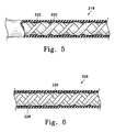
- Figure 5 shows another variation of the inventive catheter section (218) in which the braid is constructed of ribbons of different width.
- the section (218) includes a braid having a wide ribbon (220) and a narrower ribbon (222).
- this various ribbons should be, in the main, super-elastic alloy.
- they may be fibrous materials such as Kevlar or materials of other metals or alloys such as stainless steel.
- the major portion of the ribbons making up a braid should be super-elastic alloy.
- FIG. 6 shows a variation of the inventive catheter section (226) in which the braid (228) was woven using a double-ribbon wind. In this variation, a pair of ribbons is placed side by side and treated as the single ribbon was in the variations described in Figures 2-5 above. This variation produces a braid which is denser than the single-ribbon wind. It is also thicker. Typically, the regions between adjacent winds are smaller.
- the invention described herein is intended to encompass multiple-wind braids.
- the stiffness of the catheter section substantially increases as the number of ribbons used in a multiple-ribbon weave is increased.
- the catheter sections shown in Figures 2, 3, 4, 5 and 6 may be combined in a variety of manners to produce a composite catheter assembly.
- the typical vascular catheter is made up of a number of sections, typically each more flexible than the section more proximal.
- Figures 7-13 show various ways to utilize the catheter sections of this invention in producing a catheter with sections of differing stiffness.
- catheter assembly (224) uses a single length of braid (226) extending from the proximal end of the catheter assembly (224) throughout the proximal section of the catheter (228) and throughout the midsection of the catheter (230).
- the distal section of the catheter (232) does not have braid (226) within.
- the difference in flexibility between proximal section (228) and midsection (230) lies in the fact that the inner liner members (234) in midsection (230) and inner liner (236) in proximal catheter section (228) are of differing moduli of elasticity.
- the outer layer (238) is a single piece of shrink-wrap tubing, e.g., polyethylene, which extends both other the composite proximal end (228) and midsections (226). It extends to form the distal section as well.
- shrink-wrap tubing e.g., polyethylene
- FIG 8 shows another variation of a catheter assembly made using multiple layers of braided sections made according to the invention.
- This catheter assembly (240) uses a proximal section (242) made up of a number of layers but including an inner braid (244) and an outer braid (246).
- the inner braid (244) also extends down into and extends through the length of midsection (248).
- the inner liner member (250) coextends, is coaxial with, and is internal to the inner braid (244).
- a middle layer of a polymeric tubing (254) extends from the proximal end of the catheter to the distal end of the catheter and forms the distal portion (252) of that catheter assembly.
- a further outer covering (256) covers braid (246).
- catheter assembly (260) includes a tubing liner (262) which extends throughout the complete catheter assembly (260) from proximal section (264) through midsection (266) to distal section (268). More importantly, the braid (270) also coextends the length of inner liner (262). Differences in flexibility for the respective sections are provided by the use of polymeric tubing members (272) for the proximal section (264) and midsection tubing member (274) for the catheter assembly midsection (266). The absence of additional polymeric members other than the outer polymeric covering (276) renders distal section (268) the most flexible.
- Figure 10 shows a preferred variation of the invention in which the braided member (275) is surrounded by an inner polyurethane layer (277) and an upper polyurethane layer (279).
- the innermost layer (281) is a tubular member comprised of TFE which preferably has been etched (as discussed above) so to provide a good bond with the adjacent polyurethane layer.
- the outermost layer (283) is also made of a polyurethane.
- the section (285) also is shown with a radio-opaque band (287) in the distal end.
- the various polyurethanes vary in hardness according to their position on the section.
- the outermost layer (283) and the upper layer (279) might be one having a Shore 75A-85A hardness; the inner layer (277) might be a Shore 55D polyurethane or the like.
- Various spacers and adhesives have been omitted from the depiction of the variations to simplify those drawings.
- Figures 11 and 12 show cross-sectional, partial cutaways of catheter assemblies utilizing braided catheter sections joined to more distal catheter sections made in other ways.
- a coil (282) is placed in the more distal portion of the catheter assembly. It abuts the single-layer of braid (284) axially.
- a ribbon (286) is used in the distal portion (288) of catheter assembly (290). The braid is used only in the remaining portion of the catheter assembly (290).
- Figures 13 and 14 depict other embodiments of the invention in which various distal sections are integrated into a section of a catheter having a braid member as is discussed above.
- Figure 13 shows a variation (300) of the invention in which the braid (302) is sandwiched between two polymeric layers, the outer layer (304) and the inner layer (306).
- a section (308) Distal to the braided section is a section (308) having an interior surface feature comprising a hard or lubricious polymeric strand (310) helically wound to provide a contact surface for guidewires and the like as they pass through the distal catheter lumen.
- the helically wound interior strand (310) may be embedded into the exterior polymer (304) or otherwise adhered to the catheter distal portion.
- a highly preferred polymer for the strand (310) is polytetrafluoroethylene and other similar polymers.
- Figure 14 shows another variation of the inventive catheter using a largely polymeric tip section but configured to resist kinking in a way different than that found in conjunction with the braid reinforced catheter section.
- Figure 14 shows a distal section (322) having a single radio-opaque marker (320).
- a comparatively inflexible radio-opaque marker in the typical extremely flexible distal section represents an exceptional challenges in producing a kink-resistant tube. The challenge is especially acute when the two-marker variation is considered. Under high flexure, the region just adjacent the markers is likely to kink and then bind upon advancement of the relatively rigid vaso-occlusive devices, particularly when the diameter of the vaso-occlusive device is close in size to the inner diameter of the open lumen.
- a single layer of a polymer which is flexible enough to function effectively as a distal section for tracking through the cerebral vasculature often is insufficiently strong to maintain its interior shape in the critical region near the radio-opaque markers.
- Increasing the thickness of the layer to alleviate the kinking problem raises the stiffness of the section often to marginally unacceptable levels.
- the dual goals of enhanced kink-resistance and acceptable flexibility may be met especially when the abuts the marker rather than over- or under-lapping the marker.
- Figure 14 shows a distal section (322) having a single distal radio-opaque marker (320).
- the single radio-opaque marker (320) is shown to be a coil although the marker may be a band.
- the outer tubing (324) and the marker may be strengthened in this region of the catheter by the introduction of the thin inner stiffener layer (326).
- Also shown are a variety of spacer sections used to hold various components in place during assembly and to maintain those position during later use. These sections are the distal radio-opaque coil marker spacers (328 and 330) and the transition spacer (332) between the distal section of the catheter and the midsection (334) containing the braid member (336).
- the inner liner (338) in that midsection (334) is also shown. In some instances, it may not be necessary to utilize an independent midsection but instead a single proximal section may abut the transition spacer (332).
- the outer layer (324) may be of a wide variety of materials such as polyurethanes, polyvinyl chloride, LDPE, LLDPE, the outer layer (324) is desirably a shrinkable tubing having an EVA content of at least 7-10% EVA, preferably 12-20% and a wall thickness of 0.0127 to 0.254 mm (0.0005 to 0.010"), preferably about 0.0762 mm (0.003").
- the inner liner (326) preferably is a similar composition but with a lower (or, preferably, no) EVA.
- the preferred material is LLDPE or LDPE.
- the wall thickness of such tubing may be 0.013 to 0.051 mm (0.0005 to 0.0020"), preferably about 0.038 mm (0.0015").
- the stiffness of this combination of materials typically produces a lateral stiffness measured as an axial deflection force of no more than about 3.0 gm, preferably no more than about 2.2 gm.
- This stiffness is measured by placing a 3 cm length of the section in a position normal or directly perpendicular to a plate connected to a meter capable of measuring force against the plate. The section is moved directly perpendicular to the measuring plate and the force measured. The measured force typically increases to a plateau as the section bends against the measuring plate. The value of that measured plateau is used in assessing the stiffness of the catheter section.
- this distal catheter section (322) exhibits comparatively high performance kink resistance e.g. the catheter section has a critical bend diameter (D cb ) of no more than about 6.0 mm, preferably no more than about 4.0 mm. Only if the critical bend diameter of the midsection (334) is no more than 3 mm is the catheter section in accordance with the present invention.
- D cb critical bend diameter
- the outer layer (324) may also be applied by dipping the inner tubing layer (326) into a molten polymer bath or into a polymer dissolved in a solid or into a suspension or latex comprising the outer cover polymer.
- the cover may be placed on the catheter by spraying or otherwise applying the material. Included in such a class are the polyurethanes, polysilicones, polyvinylpyrrolidone, etc.
- the distal catheter section (322) may be coated or otherwise treated both inside and outside to increase their lubricity.
- the distal catheter section (322) noted in Figure 14 is especially suitable for use with the kink-resistant sections comprising braided members discussed above in those instances in which a metal containing distal tip is not optimum.
- Figure 15 shows the use of a shaping mandrel in forming one of the distal tips (342) discussed above. It should be understood that although the majority of the preferred embodiments of the invention are both quite kink-resistant and quite flexible, it is within the purview of the generic concept of this invention that the distal tip of the catheter may be given a non-linear "pre-shape" sufficient to aid the movement of the catheter through the vasculature.
- mandrel (340) also produces a very smooth inner surface in the catheter approximating the finish of the mandrel itself. Occasionally, the designer will need add a layer of polymer to enhance the stiffness of the section to allow maintenance of the tip shape during use.
- the catheter sections of this invention may be used in conjunction with other catheter portions which are more proximal to the individual sections discussed above.
- Figure 16 depicts, in partial cross section, a typical joint as might be found between a more-proximal section comprising metallic tubing and a braided more-distal section.
- the more distal-section of the invention is adjacent the more-proximal catheter section of the invention.
- the braid (408) in the more-distal section (400) is soldered or welded or otherwise attached to the more-proximal segment (402).
- An outer covering (404) such as has been discussed above may be applied to the outer surface of both the more-distal section (400) and the more-proximal segment (402).
- the outer covering (404) may be a material of suitable flexibility and compatibility such as a polyurethane or low density polyethylene and obviously may be covered or coated with a lubricious polymeric material such as a hydrophilic polymer material, e.g., one containing polyvinylpyrrolidone.
- a lubricious polymeric material such as a hydrophilic polymer material, e.g., one containing polyvinylpyrrolidone.
- the more-distal catheter section (400), as well as the stiffer more-proximal section, may include a lubricious inner layer (not shown), e.g., a Teflon (Trade mark) or similar, as as been discussed above.
- vaso-occlusive devices operate in the following manner: a vaso-occlusive device which is attached to the end of a conductive core wire (via a sacrificial joint) is passed through the vasculature until a desired site is reached.
- the vaso-occlusive device is at (or in) the desired site; the sacrificial joint is in contact with the local body fluid or a conductive fluid, e.g., saline solution, introduced through the catheter.
- a small electric current is then passed through the core wire, perhaps with a superimposed RF component.
- a current is passed through the core wire with the expectation that the current will cause the sacrificial joint between the vaso-occlusive device and the distal tip of the core wire to electrolytically dissolve or disintegrate thereby freeing the vaso-occlusive device.
- the current "return" circuit is formed through the blood and thence to a skin patch attached to the current supply source.
- the Mills catheter uses the catheter as a return leg of the electrical circuit used to electrolytically dissolve the sacrificial link to the vaso-occlusive device.
- Figure 16 shows at the distal-most portion of the section (400) a series of small ports (410) through outer wall covering (404). These small ports (410) are often no more than about 0.15 mm (0.006") in diameter but allow access of the body fluid to the metallic braid (408) to form a portion of the circuit. Also shown are two radio-opaque bands (412), of e.g., platinum, to allow more certain visualization of the catheter tip during the procedure.
- the inner liner is not required in all procedures using this catheter assembly, when a vaso-occlusive device such as those described in the Guglielmi et al, Scheldrup, and Mills documents is used, the liner is highly desirable as an insulator so to isolate the core wire electrically from the metallic braid and further to isolate the electrolytic or electrical activity at the sacrificial joint.
- the braid (408) is used as a conductor, it may be desirable to include a better conductor, e.g., gold, silver, copper, platinum, as one or more of the ribbons making up the braid.
- the super-elastic alloy ribbons may be plated with such a conductor so to improve the conductivity of the braid/metallic tube assembly.
- the metallic more-proximal section (402) may be used simply as a stiff proximal portion if the designer so desires.
- Figure 17 depicts in partial cross-section another variation of the invention in which a more-distal segment (430) is attached to the more-proximal segment (432) via a conical or scarf joint (434).
- the depicted sections have a common lubricious inner layer (436), e.g., a Teflon (Trade mark) or similar, as has been discussed above.
- This inner layer (436) is optional and need not be found in each such segment. Nevertheless, the inner layer provides a for a number of benefits: it may form the cover for a mandrel upon which the adjacent layer (438) and then upon which the braid (408) may be wound or braided.
- the inner layer may be omitted, particularly in the more proximal region (432) since the majority of materials which are suitable for the more proximal section are very "hard” and suitably slippery for passage of guidewires and the like.
- the more-proximal section (432) may be a simple tubular member comprising unfilled, filled, or fiber-reinforced, tough, polymeric materials preferably having high flexural moduli.
- Examples generically include polyamides (Nylons 6, 66, 69, 610, 612, 46, 11 (Trade marks), and aromatic polyamides such as supplied by DuPont, Huls, etc.), polyamide-polyimides (such as those supplied by Amoco Performance Products), polyimides (both thermoset and thermoplastic), polycarbonates, LCP's, acetals (such as Delrin), and (preferably) stiffer polyolefins such as polypropylene or high density polyethylene, etc.
- the choice of materials for the proximal section is desirably a polyamide which is melt-miscible with a polymeric component found in the next more distal segment.
- the more distal region (430) may(for instance) have a covering (440) of polyurethane, a block copolymer of a polyether and a polyamide (e.g., a Pebax), or a low durometer Nylon (Trade mark).
- a covering (440) of polyurethane, a block copolymer of a polyether and a polyamide e.g., a Pebax
- a low durometer Nylon Trade mark
- the outer covering (440) and the more distal section (432) may be covered or coated with a lubricious polymeric material such as a hydrophilic polymer material. It is also highly desirable to choose a translucent or transparent polymer for this section to assist the physician in use of the catheter assembly.
- the exemplified catheter assemblies in the Figures utilize only two or three sections, this invention is not so limited.
- the number of sections is selected by the designer when conceptualizing a specific use for a chosen device. Often, the optimum number of sections ends up being three simply because of the physiology of the human body, however, three or more may be involved in this invention.
- the sections additionally need not be of constant stiffness. They may also vary in stress -- typically as the distal end of a section is approached, the section becomes more flexible.
- a catheter section (450) is placed between two plates (desirably of plastic or glass or the like for visibility) and often with an optional peg (455) to hold the catheter section loop (454) in place.
- the ends of the catheter are then pulled until a kink appears in the body of the catheter.
- the ratio of the outer diameters (major diameter:minor diameter) as measured at apex (454) reaches a value of 1.5.
- Figure 18B shows the cross section of the catheter sector at (454) against the peg (455) and further shows the manner in which the major diameter and the minor diameter are measured.
- region we mean within 15% of the point specified.
- distal region of the distal section would refer to the most distal 15% in length of the distal section.
- the catheter was completely lined from proximal end to distal end.
- the braid extended from proximal end to distal end.
- the braid was woven from eight ribbons of a commercial nitinol alloy containing about 2% Cr (sold by Shape Memory Applications Co. of Santa Clara, CA.).
- the alloy had a thermal transition temperature (between austenitic and martensitic phases) of -10°C.
- the braid was placed on a 0.6 mm (0.024”) diameter stainless steel mandrel and heat-treated at 343-371°C (650-700°F) for 15-30 minutes to permit the braid to maintain its shape.
- a liner of a PTFE/FEP blend tubing was placed within the braid.
- the proximal section was covered with a tubing of Shore 72D polyurethane; the midsection was covered with a tubing of Shore 60D polyurethane; the distal section was covered with a tubing of Shore 85A polyurethane.
- the polyurethane tubing members were of a commercial resin sold under the CARBOTHANE trademark.
- the resulting catheter had a 0.96 mm (0.038”) O.D.
- the distal section had a critical bend diameter (D cb ) of 3 mm.
- Example 2 We constructed a second catheter also having three regions of differing flexibility of the same polymers as the catheter in Example 1. The most distal region was the most flexible. In this instance, the catheter was completely lined from proximal end to distal end with a nitinol ribbon coil. The ribbon was a 0.025 mm (1 mil) by 0.15 mm (6 mil) nitinol ribbon which was tightly wound, i.e. with substantially no space between adjacent turns. The braid extended from proximal end to distal end axially between the ribbon coil and the polymeric outer covering. The braid was again woven from eight ribbons of the alloy mentioned in Example 1. The outer covering was of the same composition as the Example 1 catheter. The resulting catheter had a 0.97 mm (0.038”) O.D. The distal section appeared to have a critical bend diameter (D cb ) of 2.5 mm.
- D cb critical bend diameter
Claims (54)
- Katheterabschnitt (102, 200, 201, 208, 218, 226, 280, 290), welcher folgendes umfaßt:
ein langgestrecktes rohrförmiges Element mit einem proximalen Ende und einem distalen Ende und einem Kanal, der ein zwischen jenen Enden verlaufendes Innenlumen begrenzt, umfassend:dadurch gekennzeichnet, daß:(a) ein rohrförmiges Litzenelement (205, 206, 220, 222, 226, 228, 244, 270, 275, 284, 302, 408), das aus einer Vielzahl von Bändern gewebt ist, wobei zumindest ein Großteil dieser Bänder eine superelastische Legierung umfaßt, und das eine Innenseite und eine Außenseite besitzt, wobei sich das Litzenelement entlang wenigstens eines Teils des Lumens erstreckt,(b) wenigstens ein polymeres inneres Auskleidungselement (204, 214, 234, 236, 250, 262, 277, 306, 326, 436) auf der Innenseite des Litzenelements; und(c) wenigstens ein äußeres Überzugselement (202, 216, 238, 254, 283, 304, 324, 404, 440) auf der Außenseite des Litzenelements;das Litzenelement (205, 206, 220, 222, 226, 228, 244, 270, 275, 284, 302, 408) nach dem Weben der Bänder einer Wärmebehandlung unterzogen wurde, so daß die Litze beim anschließenden Gebrauch ihre Form behält und die aus einer superelastischen Legierung bestehenden Bänder in der Litze ihre superelastischen Eigenschaften behalten; undder Katheterabschnitt so konstruiert und angeordnet ist, daß er einen kritischen Biegedurchmesser (Dcb) von nicht mehr als 3 mm besitzt. - Katheter (100, 224, 260), welcher folgendes umfaßt:
ein langgestrecktes rohrförmiges Element mit einem proximalen Ende und einem distalen Ende und einem Kanal, der ein zwischen jenen Enden verlaufendes Innenlumen begrenzt,
wobei das langgestreckte rohrförmige Element folgendes aufweist:wobei wenigstens das mehr distal gelegene Segment des langgestreckten rohrförmigen Elements folgendes umfaßt:(a) ein relativ steifes, mehr proximal gelegenes Segment (106, 228, 242, 266, 432), und(b) ein relativ biegsames, mehr distal gelegenes Segment (102, 230, 248, 268, 430),wobei das mehr distal gelegene Segment so konstruiert und angeordnet ist, daß es einen kritischen Biegedurchmesser (Dcb) von nicht mehr als 3 mm besitzt.(i) ein rohrförmiges Litzenelement (206, 220, 222, 226, 228, 270, 275, 408), das aus einer Vielzahl von Bändern gewebt ist, wobei zumindest ein Großteil der Bänder eine superelastische Legierung umfaßt, und das eine Innenseite und eine Außenseite besitzt, wobei das Litzenelement nach dem Weben der Bänder einer Wärmebehandlung unterzogen wurde, so daß die Litze beim anschließenden Gebrauch ihre Form behält und die aus einer superelastischen Legierung bestehenden Bänder in der Litze ihre superelastischen Eigenschaften behalten,(ii) wenigstens ein polymeres inneres Auskleidungselement (204, 214, 234, 250, 262, 277, 436) auf der Innenseite des Litzenelements, und(iii) wenigstens ein äußeres Überzugselement (202, 216, 238, 254, 283, 440) auf der Außenseite des Litzenelements, - Katheterabschnitt oder Katheter nach Anspruch 1 oder Anspruch 2, bei dem wenigstens eines von dem wenigstens einen äußeren Überzugselement (202, 216, 238, 254, 283, 304, 324, 404, 440) ein Polymer umfaßt.
- Katheterabschnitt oder Katheter nach Anspruch 3, bei dem die Polymere ausgewählt sind aus Elementen, die ausgewählt sind aus der Gruppe umfassend Polyimide, Polyamide, Polyester, Polyethylen, Polypropylen, Polyvinylchlorid, Polyfluorkohlenstoffe, Polyurethane, Polysulfone und deren Mischungen, Legierungen, Gemische, Copolymere und Blockcopolymere.
- Katheterabschnitt oder Katheter nach einem der vorhergehenden Ansprüche, bei dem das wenigstens eine polymere innere Auskleidungselement (204, 214, 234, 236, 250, 262, 277, 306, 326, 436) auf der Innenseite des Litzenelements einen Polyfluorkohlenstoff umfaßt.
- Katheterabschnitt nach Anspruch 1, bei dem das wenigstens eine polymere innere Auskleidungselement (204, 214, 234, 236, 250, 262, 277, 306, 326, 436) auf der Innenseite des Litzenelements (205, 206, 220, 222, 226, 228, 244, 270, 275, 284, 302, 408) aus Fluorkohlenstoff besteht und das wenigstens eine Überzugselement (202, 216, 238, 254, 283, 304, 324, 404, 440) auf der Außenseite des Litzenelements aus Polyurethan besteht.
- Katheterabschnitt oder Katheter nach Anspruch 5 oder Anspruch 6, bei dem das wenigstens eine polymere innere Auskleidungselement (204, 214, 234, 236, 250, 262, 277, 306, 326, 436) auf der Innenseite des Litzenelements Polytetrafluorethylen umfaßt.
- Katheterabschnitt oder Katheter nach Anspruch 7, bei dem das wenigstens eine polymere innere Auskleidungselement auf der Innenseite des Litzenelements des weiteren ein äußeres Auskleidungselement aus Polyurethan zwischen dem Litzenelement und dem Polytetrafluorethylen umfaßt.
- Katheterabschnitt oder Katheter nach Anspruch 8, bei dem das wenigstens eine äußere Auskleidungselement aus Polyurethan auf der Innenseite des Litzenelements mit dem Polytetrafluorethylen in Kontakt steht.
- Katheterabschnitt oder Katheter nach einem der Ansprüche 7 bis 9, bei dem das Polytetrafluorethylen zwischen dem distalen und dem proximalen Ende liegt.
- Katheterabschnitt nach Anspruch 1, bei dem das wenigstens eine innere Auskleidungselement (204, 214, 234, 236, 250, 262, 277, 306, 326, 436) auf der Innenseite des Litzenelements aus Polypropylen besteht und das wenigstens eine äußere Überzugselement (202, 216, 238, 254, 283, 304, 324, 404, 440) auf der Außenseite des Litzenelements aus Polyethylen besteht.
- Katheterabschnitt nach Anspruch 11, bei dem das Auskleidungselement aus Polypropylen zwischen dem distalen Ende und dem proximalen Ende liegt.
- Katheterabschnitt nach Anspruch 1, bei dem das Litzenelement (205, 206, 220, 222, 226, 228, 244, 270, 275, 284, 302, 408) zwischen dem distalen Ende des Abschnitts und dem proximalen Ende des Abschnitts liegt.
- Katheterabschnitt oder Katheter nach einem der vorhergehenden Ansprüche, bei dem die superelastische Legierung eine Nickel-Titan-Legierung umfaßt.
- Katheterabschnitt oder Katheter nach Anspruch 14, bei dem die Nickel-Titan-Legierung ein Legierungselement enthält, das ausgewählt ist aus der Gruppe umfassend Vanadium, Chrom, Mangan, Eisen und Cobalt.
- Katheterabschnitt oder Katheter nach Anspruch 15, bei dem das Legierungselement ausgewählt ist aus der Gruppe umfassend Chrom und Eisen.
- Katheterabschnitt oder Katheter nach einem der vorhergehenden Ansprüche, bei dem eine Minderzahl der Bänder (205, 206, 220, 222, 226, 228, 244, 270, 275, 284, 302, 408) des Litzenelements aus Edelstahl besteht.
- Katheterabschnitt oder Katheter nach einem der Ansprüche 1 bis 16, bei dem eine Minderzahl der Bänder (205, 206, 220, 222, 226, 228, 244, 270, 275, 284, 302, 408) des Litzenelements ein Element umfaßt, das ausgewählt ist aus der Gruppe umfassend Platin, Wolfram, Gold und deren Mischungen und Legierungen.
- Katheterabschnitt oder Katheter nach einem der Ansprüche 1 bis 16, bei dem eine Minderzahl der Bänder (205, 206, 220, 222, 226, 228, 244, 270, 275, 284, 302, 408) des Litzenelements aus einem Polymer besteht.
- Katheterabschnitt oder Katheter nach einem der Ansprüche 1 bis 16, bei dem eine Minderzahl der Bänder (205, 206, 220, 222, 226, 228, 244, 270, 275, 284, 302, 408) des Litzenelements aus Kohlefaser besteht.
- Katheterabschnitt oder Katheter nach einem der vorhergehenden Ansprüche, bei dem das Litzenelement (206, 220, 228, 244, 270, 275, 284, 302, 408) eine Litzensteigung besitzt und diese Litzensteigung entlang der Achse des Litzenelements konstant ist.
- Katheterabschnitt nach einem der Ansprüche 1 bis 20, bei dem das Litzenelement (205, 206) eine Litzensteigung besitzt und diese Litzensteigung entlang der Achse des Litzenelements nicht konstant ist.
- Katheterabschnitt oder Katheter nach einem der vorhergehenden Ansprüche, bei dem das Litzenelement (205, 206) einen Außendurchmesser besitzt und dieser Außendurchmesser entlang der Achse des Litzenelements nicht konstant ist.
- Katheterabschnitt oder Katheter nach Anspruch 23, bei dem der Außendurchmesser des Litzenelements sich entlang der Achse des Litzenelements (205, 206) verjüngt.
- Katheterabschnitt oder Katheter nach einem der vorhergehenden Ansprüche, bei dem wenigstens ein Teil der Bänder (408) des Litzenelements elektrisch leitend sind, und das wenigstens eine äußere Überzugselement durch es hindurch verlaufende Öffnungen (410) besitzt.
- Katheterabschnitt oder Katheter nach einem der vorhergehenden Ansprüche, bei dem die Bänder (205, 206, 220, 222, 226, 228, 244, 270, 275, 284, 302, 408) des Litzenelements eine Dicke zwischen 0,013 und 0,09 mm (0,5 und 3,5 mil) und eine Breite zwischen 0,025 und 0,305 mm (2,5 und 12 mil) besitzen.
- Katheterabschnitt oder Katheter nach einem der vorhergehenden Ansprüche, bei dem wenigstens eines von dem inneren Auskleidungselement (204, 214, 234, 236, 250, 262, 277, 306, 326, 436) und dem äußeren Überzugselement (202, 216, 238, 254, 283, 304, 324, 404, 440) ein strahlenundurchlässig machendes Mittel enthält.
- Katheterabschnitt oder Katheter nach einem der vorhergehenden Ansprüche, bei dem das distale Ende des Abschnitts mit Hilfe eines Dorns und mit Wärme in eine nichtlineare Form gebracht werden kann.
- Katheterabschnitt oder Katheter nach einem der vorhergehenden Ansprüche, des weiteren umfassend mehr als ein Litzenelement (244, 246), die koaxial zueinander angeordnet sind.
- Katheter nach Anspruch 2, des weiteren mit einem ganz distal gelegenen Abschnitt, der folgendes umfaßt:(a) einen äußeren rohrförmigen Überzug (324) aus einem Überzugsmaterial,(b) eine innere Versteifungseinlage (326) aus einem ersten Einlagematerial, das koaxial zu dem äußeren rohrförmigen Überzug (324) angeordnet ist, und(c) wenigstens eine distale strahlenundurchlässige Markierung (320), die distal von der inneren Versteifungseinlage angebracht ist.
- Katheter nach Anspruch 30, bei dem die innere Versteifungseinlage ein Versteifungselement aus einem spiralförmig gewickelten Band umfaßt.
- Katheter nach Anspruch 31, bei dem die innere Versteifungseinlage ein Versteifungsband aus einer superelastischen Legierung umfaßt.
- Katheter nach Anspruch 32, bei dem die superelastische Legierung eine Nickel-Titan-Legierung umfaßt.
- Katheter nach einem der Ansprüche 30 bis 33, bei dem das äußere Überzugsmaterial ein Polyethylengemisch mit mindestens 7 % EVA umfaßt.
- Katheter nach einem der Ansprüche 30 bis 34, bei dem das innere Auskleidungsmaterial Polyethylen umfaßt.
- Katheter nach einem der Ansprüche 30 bis 34, bei dem das Auskleidungsmaterial und das Überzugsmaterial strahlungssterilisierbar sind, ohne daß es dabei zu einer wesentlichen Verschlechterung ihrer physikalischen Eigenschaften kommt.
- Katheter nach Anspruch 2, des weiteren umfassend einen ganz distal gelegenen Abschnitt, welcher folgendes umfaßt:(a) ein inneres, spiralförmig gewickeltes, gleitfähiges polymeres Spiralenelement (310), das koaxial zu einem äußeren rohrförmigen Überzug (304) angeordnet ist,(b) wobei der äußere rohrförmige Überzug (304) ein polymeres Überzugsmaterial umfaßt, und(c) wenigstens eine distale strahlenundurchlässige Markierung, die im distalen Bereich des Abschnitts angebracht ist.
- Katheter nach Anspruch 37, bei dem das innere, spiralförmig gewickelte, gleitfähige polymere Spiralenelement ein Polyfluorkohlenstoffpolymer umfaßt.
- Katheter nach Anspruch 37 oder Anspruch 38, bei dem das innere, spiralförmig gewickelte, gleitfähige polymere Spiralenelement (310) wenigstens teilweise in den äußeren rohrförmigen Überzug eingebettet ist.
- Katheteranordnung, umfassend:
ein langgestrecktes rohrförmiges Element mit einem proximalen Ende und einem distalen Ende und einem Kanal, der ein zwischen jenen Enden verlaufendes Innenlumen begrenzt, wobei das rohrförmige Element folgendes umfaßt:(a) ein im Verhältnis biegsameres und mehr distal gelegenes Segment (102, 212, 230, 248, 268, 430), wobei das Segment folgendes umfaßt:wobei das Segment so konstruiert und angeordnet ist, daß es einen kritischen Biegedurchmesser (Dcb) von nicht mehr als 3 mm besitzt;(i) ein rohrförmiges Litzenelement (206, 220, 222, 226, 228, 270, 275, 408), das aus einer Vielzahl von Bändern gewebt ist, wobei zumindest der Großteil der Bänder eine superelastische Legierung umfaßt, und das eine Innenseite und eine Außenseite besitzt, wobei das Litzenelement nach dem Weben der Bänder einer Wärmebehandlung unterzogen wurde, so daß die Litze beim anschließenden Gebrauch ihre Form behält und die aus einer superelastischen Legierung bestehenden Bänder in der Litze ihre superelastischen Eigenschaften behalten,(ii) wenigstens ein inneres Auskleidungselement (204, 214, 234, 250, 262, 277, 436) auf der Innenseite des Litzenelements, und(iii) wenigstens ein äußeres Überzugselement (202, 216, 238, 254, 283, 440) auf der Außenseite des Litzenelements,
wobei das rohrförmige Element des weiteren folgendes umfaßt:(b) ein im Verhältnis steiferes und mehr proximal gelegenes rohrförmiges Segment (210, 228, 242, 266), das ein Material mit einem vergleichsweise hohen Biegemodul umfaßt. - Katheteranordnung nach Anspruch 40, bei der wenigstens eines von dem inneren Auskleidungselement und dem äußeren Überzugselement ein Polymer ist.
- Katheteranordnung nach Anspruch 41, bei der die Polymere ausgewählt sind aus Elementen, die ausgewählt sind aus der Gruppe umfassend Polyimide, Polyamide, Polyester, Polyethylen, Polypropylen, Polyvinylchlorid, Polyfluorkohlenstoffe, Polyurethane, Polysulfone und deren Mischungen, Legierungen, Gemische, Copolymere und Blockcopolymere.
- Katheteranordnung nach einem der Ansprüche 40 bis 42, bei der die superelastische Legierung eine Nickel-Titan-Legierung umfaßt.
- Katheteranordnung nach einem der Ansprüche 40 bis 43, bei der eine Minderzahl der Bänder des Litzenelements aus Edelstahl bestehen.
- Katheteranordnung nach einem der Ansprüche 40 bis 43, bei der eine Minderzahl der Bänder des Litzenelements ein Element umfassen, das ausgewählt ist aus der Gruppe umfassend Gold, Platin, Silber und Kupfer.
- Katheteranordnung nach einem der Ansprüche 40 bis 45, bei der wenigstens eines von dem inneren Auskleidungselement und dem äußeren Überzugselement strahlenundurchlässig ist.
- Katheteranordnung nach einem der Ansprüche 40 bis 46, bei der der mehr proximal gelegene Abschnitt ein Polymer umfaßt.
- Katheteranordnung nach Anspruch 47, bei der der mehr proximal gelegene Abschnitt ein Polymer umfaßt, das ausgewählt ist aus Polyamiden, Polyamid-Polyimiden, Polyimiden, Polycarbonaten, LCPs, Polyolefinen und Acetalen.
- Katheteranordnung nach Anspruch 48, bei der der mehr proximal gelegene Abschnitt ein Nylon (Warenzeichen), ein Polyimid, Polypropylen oder Polyethylen hoher Dichte umfaßt.
- Katheteranordnung nach einem der Ansprüche 40 bis 46, bei der der mehr proximal gelegene Abschnitt ein Metallrohr umfaßt.
- Katheteranordnung nach Anspruch 50, bei der der mehr proximal gelegene Abschnitt elektrisch mit der Litze verbunden ist.
- Katheteranordnung, Katheterabschnitt oder Katheter nach einem der vorhergehenden Ansprüche, bei der/dem das innere Auskleidungselement und das äußere Überzugselement strahlungssterilisierbar sind, ohne daß es dabei zu einer wesentlichen Verschlechterung der physikalischen Eigenschaften kommt.
- Katheteranordnung, Katheterabschnitt oder Katheter nach einem der vorhergehenden Ansprüche, des weiteren umfassend einen herausnehmbaren, verschieblichen Führungsdraht, der im Inneren des Abschnitts und im Verhältnis zu diesem verschieblich angeordnet ist.
- Verfahren zur Herstellung einer Katheteranordnung, eines Katheterabschnitts oder eines Katheters mit der Konstruktion gemäß einem der vorhergehenden Ansprüche, wobei das Verfahren die Wärmebehandlung der Bänder (205, 206, 220, 222, 226, 228, 244, 270, 275, 284, 302, 408) des Litzenelements umfaßt, nachdem diese zusammengewebt wurden, um das Litzenelement zu bilden, indem das Litzenelement auf einen Dorn aufgesteckt wird und für ein paar Minuten mit Wärme bei einer Temperatur von 343°-399°C (650°-750°F) beaufschlagt wird.
Applications Claiming Priority (5)
| Application Number | Priority Date | Filing Date | Title |
|---|---|---|---|
| US43044595A | 1995-04-28 | 1995-04-28 | |
| US430445 | 1995-04-28 | ||
| US521671 | 1995-08-31 | ||
| US08/521,671 US5702373A (en) | 1995-08-31 | 1995-08-31 | Composite super-elastic alloy braid reinforced catheter |
| PCT/US1996/005839 WO1996033763A2 (en) | 1995-04-28 | 1996-04-26 | High performance braided catheter |
Publications (2)
| Publication Number | Publication Date |
|---|---|
| EP0782463A2 EP0782463A2 (de) | 1997-07-09 |
| EP0782463B1 true EP0782463B1 (de) | 2000-03-01 |
Family
ID=27028603
Family Applications (1)
| Application Number | Title | Priority Date | Filing Date |
|---|---|---|---|
| EP96913194A Expired - Lifetime EP0782463B1 (de) | 1995-04-28 | 1996-04-26 | Hochleistungskatheter mit geflochtenem Element |
Country Status (11)
| Country | Link |
|---|---|
| US (1) | US6143013A (de) |
| EP (1) | EP0782463B1 (de) |
| JP (1) | JP2865428B2 (de) |
| AT (1) | ATE189964T1 (de) |
| AU (1) | AU693357B2 (de) |
| CA (1) | CA2182526C (de) |
| DE (1) | DE69606845T2 (de) |
| DK (1) | DK0782463T3 (de) |
| NO (1) | NO963273L (de) |
| TW (1) | TW326399B (de) |
| WO (1) | WO1996033763A2 (de) |
Cited By (1)
| Publication number | Priority date | Publication date | Assignee | Title |
|---|---|---|---|---|
| WO2023099556A1 (en) * | 2021-11-30 | 2023-06-08 | Biotronik Ag | Dilator shaft design enabling tip shapability and variable shaft flexibility |
Families Citing this family (257)
| Publication number | Priority date | Publication date | Assignee | Title |
|---|---|---|---|---|
| US6482171B1 (en) * | 1991-07-16 | 2002-11-19 | Heartport, Inc. | Multi-lumen catheter |
| US6824553B1 (en) | 1995-04-28 | 2004-11-30 | Target Therapeutics, Inc. | High performance braided catheter |
| NO970866L (no) * | 1996-02-28 | 1997-08-29 | Target Therapeutics Inc | Infusjons-kateter med oppblåsbar membran |
| US5927345A (en) * | 1996-04-30 | 1999-07-27 | Target Therapeutics, Inc. | Super-elastic alloy braid structure |
| US6090099A (en) * | 1996-05-24 | 2000-07-18 | Target Therapeutics, Inc. | Multi-layer distal catheter section |
| US5782811A (en) * | 1996-05-30 | 1998-07-21 | Target Therapeutics, Inc. | Kink-resistant braided catheter with distal side holes |
| US7992572B2 (en) | 1998-06-10 | 2011-08-09 | Asthmatx, Inc. | Methods of evaluating individuals having reversible obstructive pulmonary disease |
| US7027869B2 (en) | 1998-01-07 | 2006-04-11 | Asthmatx, Inc. | Method for treating an asthma attack |
| US6634363B1 (en) | 1997-04-07 | 2003-10-21 | Broncus Technologies, Inc. | Methods of treating lungs having reversible obstructive pulmonary disease |
| US5951539A (en) * | 1997-06-10 | 1999-09-14 | Target Therpeutics, Inc. | Optimized high performance multiple coil spiral-wound vascular catheter |
| US5891114A (en) * | 1997-09-30 | 1999-04-06 | Target Therapeutics, Inc. | Soft-tip high performance braided catheter |
| US6217566B1 (en) * | 1997-10-02 | 2001-04-17 | Target Therapeutics, Inc. | Peripheral vascular delivery catheter |
| US6077258A (en) * | 1997-10-03 | 2000-06-20 | Scimed Life Systems, Inc. | Braided angiography catheter having full length radiopacity and controlled flexibility |
| US6033394A (en) * | 1997-12-05 | 2000-03-07 | Intratherapeutics, Inc. | Catheter support structure |
| US7921855B2 (en) | 1998-01-07 | 2011-04-12 | Asthmatx, Inc. | Method for treating an asthma attack |
| JP3691236B2 (ja) * | 1998-01-23 | 2005-09-07 | 朝日インテック株式会社 | カテーテル |
| US6425898B1 (en) † | 1998-03-13 | 2002-07-30 | Cordis Corporation | Delivery apparatus for a self-expanding stent |
| JPH11262529A (ja) * | 1998-03-18 | 1999-09-28 | Nippon Zeon Co Ltd | バルーンカテーテル |
| DE19816986C1 (de) * | 1998-04-17 | 1999-08-05 | Rehau Ag & Co | Verfahren zur Herstellung armierter, medizinischer Schläuche |
| EP0956878A3 (de) * | 1998-05-14 | 2001-01-10 | Terumo Kabushiki Kaisha | Intravaskulärer Katheter sowie Katheter-Nadeleinheit |
| US7198635B2 (en) | 2000-10-17 | 2007-04-03 | Asthmatx, Inc. | Modification of airways by application of energy |
| US8181656B2 (en) | 1998-06-10 | 2012-05-22 | Asthmatx, Inc. | Methods for treating airways |
| US6368316B1 (en) * | 1998-06-11 | 2002-04-09 | Target Therapeutics, Inc. | Catheter with composite stiffener |
| US6216045B1 (en) | 1999-04-26 | 2001-04-10 | Advanced Neuromodulation Systems, Inc. | Implantable lead and method of manufacture |
| CA2378720A1 (en) * | 1999-07-23 | 2001-02-01 | Tfx Medical Extrusion Products | Catheter device having multi-lumen reinforced shaft and method of manufacture for same |
| US6689120B1 (en) | 1999-08-06 | 2004-02-10 | Boston Scientific Scimed, Inc. | Reduced profile delivery system |
| EP1207930B1 (de) * | 1999-08-06 | 2005-06-22 | Boston Scientific Scimed, Inc. | Einführsystem mit reduziertem profil |
| US6579484B1 (en) * | 1999-12-16 | 2003-06-17 | Advanced Cardiovascular Systems, Inc. | Co-extruded taper shaft |
| US6752800B1 (en) * | 2000-02-18 | 2004-06-22 | Intraluminal Therapeutics Inc. | Catheter handle for controlling the advancement of a guide wire |
| ES2284633T3 (es) | 2000-03-23 | 2007-11-16 | Cook Incorporated | Vaina introductora de cateter. |
| US8251070B2 (en) | 2000-03-27 | 2012-08-28 | Asthmatx, Inc. | Methods for treating airways |
| US7344546B2 (en) | 2000-04-05 | 2008-03-18 | Pathway Medical Technologies | Intralumenal material removal using a cutting device for differential cutting |
| US10092313B2 (en) * | 2000-04-05 | 2018-10-09 | Boston Scientific Limited | Medical sealed tubular structures |
| JP2002028245A (ja) * | 2000-07-13 | 2002-01-29 | Asahi Intecc Co Ltd | カテーテル |
| US7555349B2 (en) | 2000-09-26 | 2009-06-30 | Advanced Neuromodulation Systems, Inc. | Lead body and method of lead body construction |
| US7104987B2 (en) | 2000-10-17 | 2006-09-12 | Asthmatx, Inc. | Control system and process for application of energy to airway walls and other mediums |
| US6740073B1 (en) * | 2000-12-06 | 2004-05-25 | Advanced Cardiovascular Systems, Inc. | Guiding catheter reinforcement with angled distal end |
| US6562022B2 (en) | 2000-12-13 | 2003-05-13 | Advanced Cardiovascular Systems, Inc. | Catheter with enhanced reinforcement |
| US6508806B1 (en) * | 2000-12-13 | 2003-01-21 | Advanced Cardiovascular Systems, Inc. | Catheter with multi-layer wire reinforced wall construction |
| US6632235B2 (en) | 2001-04-19 | 2003-10-14 | Synthes (U.S.A.) | Inflatable device and method for reducing fractures in bone and in treating the spine |
| DE20110121U1 (de) * | 2001-06-19 | 2002-12-05 | Braun Melsungen Ag | Katheter |
| US20030009184A1 (en) * | 2001-07-03 | 2003-01-09 | Scimed Life Systems, Inc. | Catheter having variable wire size radiopaque braid |
| US6635047B2 (en) * | 2001-08-06 | 2003-10-21 | Scimed Life Systems, Inc. | Integrated polymer and braid for intravascular catheters |
| WO2003043685A2 (en) * | 2001-11-19 | 2003-05-30 | Cardiovascular Systems, Inc | High torque, low profile intravascular guidewire system |
| ATE520362T1 (de) | 2001-12-03 | 2011-09-15 | Ekos Corp | Katheter mit mehreren ultraschall-abstrahlenden teilen |
| US7065394B2 (en) * | 2001-12-12 | 2006-06-20 | Medtronic, Inc | Guide catheter |
| US20040073158A1 (en) * | 2001-12-12 | 2004-04-15 | Medtronic, Inc. | Guide catheter |
| US20040175525A1 (en) * | 2002-02-28 | 2004-09-09 | Scimed Life Systems, Inc. | Catheter incorporating an improved polymer shaft |
| US20030167051A1 (en) * | 2002-02-28 | 2003-09-04 | Pu Zhou | Intravascular catheter shaft |
| DE10259002B4 (de) * | 2002-03-20 | 2016-07-14 | Manfred Sauer | Katheter |
| DK1485158T3 (da) * | 2002-03-20 | 2008-06-02 | Manfred Sauer | Kateter |
| US7115134B2 (en) * | 2002-07-22 | 2006-10-03 | Chambers Technology, Llc. | Catheter with flexible tip and shape retention |
| DE60330478D1 (de) | 2002-10-10 | 2010-01-21 | Micro Therapeutics Inc | Mit drahtgeflecht verstärkter mikrokatheter |
| US6923754B2 (en) * | 2002-11-06 | 2005-08-02 | Senorx, Inc. | Vacuum device and method for treating tissue adjacent a body cavity |
| US8328710B2 (en) * | 2002-11-06 | 2012-12-11 | Senorx, Inc. | Temporary catheter for biopsy site tissue fixation |
| US7005026B2 (en) * | 2002-11-15 | 2006-02-28 | Applied Medical Resources Corporation | Kink-resistant access sheath and method of making same |
| JP2006516203A (ja) * | 2002-11-18 | 2006-06-29 | メディガイド リミテッド | Mpsセンサーをカテーテル上に取り付ける方法及びシステム |
| JP4013194B2 (ja) * | 2002-12-02 | 2007-11-28 | 株式会社町田製作所 | 内視鏡等の可撓管およびその製造方法 |
| JP2006508744A (ja) * | 2002-12-04 | 2006-03-16 | レイク リージョン マニュファクチュアリング インコーポレイテッド | 標識付きガイドワイヤ |
| US8377035B2 (en) * | 2003-01-17 | 2013-02-19 | Boston Scientific Scimed, Inc. | Unbalanced reinforcement members for medical device |
| US7393339B2 (en) * | 2003-02-21 | 2008-07-01 | C. R. Bard, Inc. | Multi-lumen catheter with separate distal tips |
| US7438712B2 (en) * | 2003-03-05 | 2008-10-21 | Scimed Life Systems, Inc. | Multi-braid exterior tube |
| US20040199052A1 (en) | 2003-04-01 | 2004-10-07 | Scimed Life Systems, Inc. | Endoscopic imaging system |
| EP1619995A2 (de) | 2003-04-22 | 2006-02-01 | Ekos Corporation | Ultraschallverstärkter zentralvenöser katheter |
| US20040226556A1 (en) | 2003-05-13 | 2004-11-18 | Deem Mark E. | Apparatus for treating asthma using neurotoxin |
| US20040243095A1 (en) | 2003-05-27 | 2004-12-02 | Shekhar Nimkar | Methods and apparatus for inserting multi-lumen spit-tip catheters into a blood vessel |
| US7597830B2 (en) * | 2003-07-09 | 2009-10-06 | Boston Scientific Scimed, Inc. | Method of forming catheter distal tip |
| US20050027340A1 (en) * | 2003-07-29 | 2005-02-03 | Micronet Medical, Inc. | System and method for providing a medical lead body having dual conductor layers |
| US20050027339A1 (en) * | 2003-07-29 | 2005-02-03 | Micronet Medical, Inc. | System and method for providing a medical lead body |
| US20050027341A1 (en) * | 2003-07-29 | 2005-02-03 | Micronet Medical, Inc. | System and method for providing a medical lead body having conductors that are wound in opposite directions |
| US7824392B2 (en) | 2003-08-20 | 2010-11-02 | Boston Scientific Scimed, Inc. | Catheter with thin-walled braid |
| US7662328B2 (en) | 2003-09-02 | 2010-02-16 | Boston Scientific Scimed, Inc. | Proximal guidewire port |
| US8636714B2 (en) * | 2003-09-22 | 2014-01-28 | Boston Scientific Scimed, Inc. | Microcatheter with sleeved guidewire port |
| US7955313B2 (en) | 2003-12-17 | 2011-06-07 | Boston Scientific Scimed, Inc. | Composite catheter braid |
| CA2551831A1 (en) * | 2004-01-29 | 2005-08-11 | Ekos Corporation | Small vessel ultrasound catheter |
| US20050177185A1 (en) * | 2004-02-05 | 2005-08-11 | Scimed Life Systems, Inc. | Counterwound coil for embolic protection sheath |
| US8608727B2 (en) * | 2004-03-01 | 2013-12-17 | Smiths Medical Asd, Inc. | Delivery system and method |
| US8252014B2 (en) | 2004-03-03 | 2012-08-28 | Innovational Holdings Llc. | Rapid exchange balloon catheter with braided shaft |
| US7844344B2 (en) | 2004-03-30 | 2010-11-30 | Medtronic, Inc. | MRI-safe implantable lead |
| EP1768724A4 (de) * | 2004-06-07 | 2010-08-25 | Bard Inc C R | Subkutane infusionsvorrichtungen |
| US8992454B2 (en) | 2004-06-09 | 2015-03-31 | Bard Access Systems, Inc. | Splitable tip catheter with bioresorbable adhesive |
| US20060036233A1 (en) * | 2004-08-12 | 2006-02-16 | Scimed Life Systems, Inc. | Catheter incorporating a guidewire exit ramp |
| US7306585B2 (en) | 2004-09-30 | 2007-12-11 | Engineering Resources Group, Inc. | Guide catheter |
| US7949407B2 (en) | 2004-11-05 | 2011-05-24 | Asthmatx, Inc. | Energy delivery devices and methods |
| WO2006052940A2 (en) | 2004-11-05 | 2006-05-18 | Asthmatx, Inc. | Medical device with procedure improvement features |
| US7662082B2 (en) | 2004-11-05 | 2010-02-16 | Theragenics Corporation | Expandable brachytherapy device |
| US20070093802A1 (en) | 2005-10-21 | 2007-04-26 | Danek Christopher J | Energy delivery devices and methods |
| US20060111649A1 (en) * | 2004-11-19 | 2006-05-25 | Scimed Life Systems, Inc. | Catheter having improved torque response and curve retention |
| US7815599B2 (en) | 2004-12-10 | 2010-10-19 | Boston Scientific Scimed, Inc. | Catheter having an ultra soft tip and methods for making the same |
| EP1871453B1 (de) * | 2005-04-20 | 2010-02-24 | Cook Incorporated | Schmelzgebundenes gelenk für medizinprodukt |
| US8652193B2 (en) | 2005-05-09 | 2014-02-18 | Angiomed Gmbh & Co. Medizintechnik Kg | Implant delivery device |
| JP4544526B2 (ja) * | 2005-06-23 | 2010-09-15 | 株式会社プラ技研 | カテーテル |
| EP1916962A1 (de) * | 2005-08-18 | 2008-05-07 | Salviac Limited | Abgabekatheter für einen embolie-schutzfilter |
| JP4790349B2 (ja) * | 2005-08-30 | 2011-10-12 | 株式会社パイオラックスメディカルデバイス | カテーテル |
| US9084694B2 (en) * | 2005-09-09 | 2015-07-21 | Boston Scientific Scimed, Inc. | Coil shaft |
| US8273006B2 (en) | 2005-11-18 | 2012-09-25 | Senorx, Inc. | Tissue irradiation |
| US8079946B2 (en) * | 2005-11-18 | 2011-12-20 | Senorx, Inc. | Asymmetrical irradiation of a body cavity |
| US7413539B2 (en) * | 2005-11-18 | 2008-08-19 | Senorx, Inc. | Treatment of a body cavity |
| US20080091169A1 (en) | 2006-05-16 | 2008-04-17 | Wayne Heideman | Steerable catheter using flat pull wires and having torque transfer layer made of braided flat wires |
| US20080234660A2 (en) * | 2006-05-16 | 2008-09-25 | Sarah Cumming | Steerable Catheter Using Flat Pull Wires and Method of Making Same |
| US7890174B2 (en) * | 2006-06-02 | 2011-02-15 | Cardiac Pacemakers, Inc. | Medical electrical lead with deployable fixation features |
| US9067041B2 (en) | 2006-09-13 | 2015-06-30 | Kawasumi Laboratories, Inc. | Microcatheter |
| US7931647B2 (en) | 2006-10-20 | 2011-04-26 | Asthmatx, Inc. | Method of delivering energy to a lung airway using markers |
| US7610101B2 (en) | 2006-11-30 | 2009-10-27 | Cardiac Pacemakers, Inc. | RF rejecting lead |
| US9950141B2 (en) * | 2006-12-29 | 2018-04-24 | St. Jude Medical, Atrial Fibrillation Division, Inc. | Dual braid reinforcement deflectable device (sheath or catheter) |
| US8182466B2 (en) * | 2006-12-29 | 2012-05-22 | St. Jude Medical, Atrial Fibrillation Division, Inc. | Dual braided catheter shaft |
| US9114229B2 (en) | 2006-12-29 | 2015-08-25 | St. Jude Medical, Af Division, Inc. | Dual braid reinforcement deflectable device |
| US10182833B2 (en) | 2007-01-08 | 2019-01-22 | Ekos Corporation | Power parameters for ultrasonic catheter |
| US9044593B2 (en) | 2007-02-14 | 2015-06-02 | Medtronic, Inc. | Discontinuous conductive filler polymer-matrix composites for electromagnetic shielding |
| US8287442B2 (en) * | 2007-03-12 | 2012-10-16 | Senorx, Inc. | Radiation catheter with multilayered balloon |
| US8740873B2 (en) * | 2007-03-15 | 2014-06-03 | Hologic, Inc. | Soft body catheter with low friction lumen |
| US20080228023A1 (en) * | 2007-03-15 | 2008-09-18 | Senorx, Inc. | Soft body catheter with low friction lumen |
| JP5024367B2 (ja) * | 2007-03-23 | 2012-09-12 | 富士通株式会社 | 電子装置、電子装置が実装された電子機器、電子装置が装着された物品、および電子装置の製造方法 |
| US20080293999A1 (en) * | 2007-04-20 | 2008-11-27 | Vision - Sciences Inc. | Medical devices with portions having different rigidity |
| US8483842B2 (en) | 2007-04-25 | 2013-07-09 | Medtronic, Inc. | Lead or lead extension having a conductive body and conductive body contact |
| EP2494932B1 (de) | 2007-06-22 | 2020-05-20 | Ekos Corporation | Vorrichtung zur Behandlung von intrakranialen Blutungen |
| US8235983B2 (en) | 2007-07-12 | 2012-08-07 | Asthmatx, Inc. | Systems and methods for delivering energy to passageways in a patient |
| US8066660B2 (en) | 2007-10-26 | 2011-11-29 | C. R. Bard, Inc. | Split-tip catheter including lateral distal openings |
| US8292841B2 (en) | 2007-10-26 | 2012-10-23 | C. R. Bard, Inc. | Solid-body catheter including lateral distal openings |
| US9579485B2 (en) | 2007-11-01 | 2017-02-28 | C. R. Bard, Inc. | Catheter assembly including a multi-lumen configuration |
| WO2009059220A1 (en) | 2007-11-01 | 2009-05-07 | C.R. Bard, Inc. | Catheter assembly including triple lumen tip |
| US7841994B2 (en) | 2007-11-02 | 2010-11-30 | Boston Scientific Scimed, Inc. | Medical device for crossing an occlusion in a vessel |
| US8275464B2 (en) * | 2007-12-06 | 2012-09-25 | Cardiac Pacemakers, Inc. | Leads with high surface resistance |
| AU2008335462B2 (en) * | 2007-12-06 | 2014-02-20 | Cardiac Pacemakers, Inc. | Implantable lead having a variable coil conductor pitch |
| EP2224995B1 (de) * | 2007-12-06 | 2015-11-25 | Cardiac Pacemakers, Inc. | Implantierbare leitung mit abschirmung |
| EP2234663A1 (de) | 2007-12-19 | 2010-10-06 | Boston Scientific Scimed, Inc. | Struktur zur verwendung als teil einer medizinischen vorrichtung |
| US8231927B2 (en) | 2007-12-21 | 2012-07-31 | Innovatech, Llc | Marked precoated medical device and method of manufacturing same |
| US7811623B2 (en) | 2007-12-21 | 2010-10-12 | Innovatech, Llc | Marked precoated medical device and method of manufacturing same |
| US8231926B2 (en) | 2007-12-21 | 2012-07-31 | Innovatech, Llc | Marked precoated medical device and method of manufacturing same |
| US8048471B2 (en) | 2007-12-21 | 2011-11-01 | Innovatech, Llc | Marked precoated medical device and method of manufacturing same |
| US7714217B2 (en) | 2007-12-21 | 2010-05-11 | Innovatech, Llc | Marked precoated strings and method of manufacturing same |
| US20090171303A1 (en) * | 2007-12-27 | 2009-07-02 | Loiterman David A | Fixed- or Variable-Length, Wire-Reinforced Catheter and Method of Adaptation |
| US20090177206A1 (en) * | 2008-01-08 | 2009-07-09 | Zimmer Spine, Inc. | Instruments, implants, and methods for fixation of vertebral compression fractures |
| US20090188098A1 (en) | 2008-01-24 | 2009-07-30 | Senorx, Inc. | Multimen brachytherapy balloon catheter |
| US9462932B2 (en) | 2008-01-24 | 2016-10-11 | Boston Scientific Scimed, Inc. | Structure for use as part of a medical device |
| US8244346B2 (en) * | 2008-02-06 | 2012-08-14 | Cardiac Pacemakers, Inc. | Lead with MRI compatible design features |
| US8483831B1 (en) | 2008-02-15 | 2013-07-09 | Holaira, Inc. | System and method for bronchial dilation |
| US9037263B2 (en) | 2008-03-12 | 2015-05-19 | Medtronic, Inc. | System and method for implantable medical device lead shielding |
| US8103360B2 (en) * | 2008-05-09 | 2012-01-24 | Foster Arthur J | Medical lead coil conductor with spacer element |
| CA2723806C (en) | 2008-05-09 | 2022-05-31 | Innovative Pulmonary Solutions, Inc. | Systems, assemblies, and methods for treating a bronchial tree |
| US9731094B2 (en) | 2008-08-20 | 2017-08-15 | Cook Medical Technologies Llc | Introducer sheath having dual reinforcing elements |
| DE102008043541A1 (de) | 2008-11-07 | 2010-05-12 | Biotronik Vi Patent Ag | Katheterschaft |
| US20100160862A1 (en) * | 2008-12-22 | 2010-06-24 | Cook Incorporated | Variable stiffness introducer sheath with transition zone |
| WO2010073646A1 (ja) * | 2008-12-26 | 2010-07-01 | 住友ベークライト株式会社 | カテーテル |
| US9579524B2 (en) | 2009-02-11 | 2017-02-28 | Hologic, Inc. | Flexible multi-lumen brachytherapy device |
| US9248311B2 (en) | 2009-02-11 | 2016-02-02 | Hologic, Inc. | System and method for modifying a flexibility of a brachythereapy catheter |
| US9084883B2 (en) | 2009-03-12 | 2015-07-21 | Cardiac Pacemakers, Inc. | Thin profile conductor assembly for medical device leads |
| US9254123B2 (en) | 2009-04-29 | 2016-02-09 | Hansen Medical, Inc. | Flexible and steerable elongate instruments with shape control and support elements |
| US8788061B2 (en) | 2009-04-30 | 2014-07-22 | Medtronic, Inc. | Termination of a shield within an implantable medical lead |
| WO2010126877A1 (en) | 2009-04-30 | 2010-11-04 | Medtronic, Inc. | Shielding an implantable medical lead |
| US10207126B2 (en) | 2009-05-11 | 2019-02-19 | Cytyc Corporation | Lumen visualization and identification system for multi-lumen balloon catheter |
| JP5542926B2 (ja) | 2009-06-26 | 2014-07-09 | カーディアック ペースメイカーズ, インコーポレイテッド | 改善されたトルク伝達性能を備えmriによる加熱を低減した単線コイルからなるコンダクタアセンブリを含む医療器具リード |
| US8335572B2 (en) * | 2009-10-08 | 2012-12-18 | Cardiac Pacemakers, Inc. | Medical device lead including a flared conductive coil |
| WO2011049684A1 (en) | 2009-10-19 | 2011-04-28 | Cardiac Pacemakers, Inc. | Mri compatible tachycardia lead |
| JP5843777B2 (ja) | 2009-10-27 | 2016-01-13 | ホライラ, インコーポレイテッド | 冷却可能なエネルギー放出アセンブリを有する送達デバイス |
| US8911439B2 (en) | 2009-11-11 | 2014-12-16 | Holaira, Inc. | Non-invasive and minimally invasive denervation methods and systems for performing the same |
| AU2010319477A1 (en) | 2009-11-11 | 2012-05-24 | Holaira, Inc. | Systems, apparatuses, and methods for treating tissue and controlling stenosis |
| AU2010337309B2 (en) * | 2009-12-30 | 2014-01-23 | Cardiac Pacemakers, Inc. | MRI-conditionally safe medical device lead |
| US8391994B2 (en) * | 2009-12-31 | 2013-03-05 | Cardiac Pacemakers, Inc. | MRI conditionally safe lead with low-profile multi-layer conductor for longitudinal expansion |
| US8798767B2 (en) * | 2009-12-31 | 2014-08-05 | Cardiac Pacemakers, Inc. | MRI conditionally safe lead with multi-layer conductor |
| US8825181B2 (en) | 2010-08-30 | 2014-09-02 | Cardiac Pacemakers, Inc. | Lead conductor with pitch and torque control for MRI conditionally safe use |
| US20130184686A1 (en) * | 2010-09-16 | 2013-07-18 | Fenwal, Inc | Flexible Medical Tubing Having Kink Resistant Properties And Methods And Apparatus To Produce The Same |
| US9314306B2 (en) | 2010-09-17 | 2016-04-19 | Hansen Medical, Inc. | Systems and methods for manipulating an elongate member |
| US9352172B2 (en) | 2010-09-30 | 2016-05-31 | Hologic, Inc. | Using a guide member to facilitate brachytherapy device swap |
| JP5604597B2 (ja) | 2010-11-18 | 2014-10-08 | カーディアック ペースメイカーズ, インコーポレイテッド | 医療装置リード線および同リード線を備える医療装置 |
| US10342992B2 (en) | 2011-01-06 | 2019-07-09 | Hologic, Inc. | Orienting a brachytherapy applicator |
| US8900652B1 (en) | 2011-03-14 | 2014-12-02 | Innovatech, Llc | Marked fluoropolymer surfaces and method of manufacturing same |
| CA2830514A1 (en) | 2011-03-22 | 2012-09-27 | Applied Medical Resources Corporation | Method of making medical tubing having drainage holes |
| US9138166B2 (en) | 2011-07-29 | 2015-09-22 | Hansen Medical, Inc. | Apparatus and methods for fiber integration and registration |
| US11291351B2 (en) * | 2011-08-19 | 2022-04-05 | Harold I. Daily | Hysteroscopes with curved tips |
| EP2765944B1 (de) | 2011-10-14 | 2018-09-05 | RA Medical Systems | Katheter mit kleinem flexiblem flüssigkern zur laserablation in körperlumen |
| WO2013066505A1 (en) | 2011-11-04 | 2013-05-10 | Cardiac Pacemakers, Inc. | Implantable medical device lead including inner coil reverse-wound relative to shocking coil |
| GB201120109D0 (en) * | 2011-11-22 | 2012-01-04 | Univ Edinburgh | Malaria vaccine |
| JP5754810B2 (ja) * | 2011-12-29 | 2015-07-29 | 朝日インテック株式会社 | カテーテル |
| US9144449B2 (en) | 2012-03-02 | 2015-09-29 | Csa Medical, Inc. | Cryosurgery system |
| EP2838609B1 (de) | 2012-04-19 | 2019-03-06 | Medtronic, Inc. | Gepaarte medizinische führungselemente mit geflochtenen leitfähigen abschirmungen mit verschiedenen physikalischen parameterwerten |
| WO2013159031A2 (en) | 2012-04-20 | 2013-10-24 | Cardiac Pacemakers, Inc. | Implantable medical device lead including a unifilar coiled cable |
| US8954168B2 (en) | 2012-06-01 | 2015-02-10 | Cardiac Pacemakers, Inc. | Implantable device lead including a distal electrode assembly with a coiled component |
| US9770293B2 (en) | 2012-06-04 | 2017-09-26 | Boston Scientific Scimed, Inc. | Systems and methods for treating tissue of a passageway within a body |
| US9592086B2 (en) | 2012-07-24 | 2017-03-14 | Boston Scientific Scimed, Inc. | Electrodes for tissue treatment |
| CN104812437B (zh) | 2012-08-31 | 2016-11-16 | 心脏起搏器股份公司 | Mri可兼容导线线圈 |
| WO2014062966A1 (en) | 2012-10-18 | 2014-04-24 | Cardiac Pacemakers, Inc. | Inductive element for providing mri compatibility in an implantable medical device lead |
| US9272132B2 (en) | 2012-11-02 | 2016-03-01 | Boston Scientific Scimed, Inc. | Medical device for treating airways and related methods of use |
| US9283374B2 (en) | 2012-11-05 | 2016-03-15 | Boston Scientific Scimed, Inc. | Devices and methods for delivering energy to body lumens |
| TW201438672A (zh) * | 2012-12-18 | 2014-10-16 | Sumitomo Bakelite Co | 醫療機器 |
| US9398933B2 (en) | 2012-12-27 | 2016-07-26 | Holaira, Inc. | Methods for improving drug efficacy including a combination of drug administration and nerve modulation |
| US10260181B2 (en) * | 2013-01-14 | 2019-04-16 | Lake Region Medical, Inc. | Directional mesh and associated systems |
| AU2013381016B2 (en) * | 2013-03-04 | 2018-12-13 | Csa Medical, Inc. | Cryospray catheters |
| US10149720B2 (en) | 2013-03-08 | 2018-12-11 | Auris Health, Inc. | Method, apparatus, and a system for facilitating bending of an instrument in a surgical or medical robotic environment |
| JP6149431B2 (ja) * | 2013-03-08 | 2017-06-21 | 住友ベークライト株式会社 | 医療用機器、カテーテルおよび医療用機器の製造方法 |
| US10376672B2 (en) | 2013-03-15 | 2019-08-13 | Auris Health, Inc. | Catheter insertion system and method of fabrication |
| JP6205785B2 (ja) * | 2013-03-28 | 2017-10-04 | 住友ベークライト株式会社 | 医療機器 |
| DE102013207109A1 (de) * | 2013-04-19 | 2014-11-06 | Henke-Sass, Wolf Gmbh | Endoskop mit einem starren gebogenen Schaft sowie Verfahren zur Herstellung eines solchen Endoskopes |
| CN111437490A (zh) * | 2013-05-19 | 2020-07-24 | 卡迪纳尔健康515瑞士有限公司 | 大管腔引导导管 |
| US9814618B2 (en) | 2013-06-06 | 2017-11-14 | Boston Scientific Scimed, Inc. | Devices for delivering energy and related methods of use |
| US10478247B2 (en) | 2013-08-09 | 2019-11-19 | Boston Scientific Scimed, Inc. | Expandable catheter and related methods of manufacture and use |
| US9962527B2 (en) | 2013-10-16 | 2018-05-08 | Ra Medical Systems, Inc. | Methods and devices for treatment of stenosis of arteriovenous fistula shunts |
| US9993638B2 (en) | 2013-12-14 | 2018-06-12 | Medtronic, Inc. | Devices, systems and methods to reduce coupling of a shield and a conductor within an implantable medical lead |
| US10426920B2 (en) * | 2013-12-20 | 2019-10-01 | Boston Scientific Scimed, Inc. | Integrated catheter system |
| EP3104933A1 (de) | 2014-02-11 | 2016-12-21 | Cardiac Pacemakers, Inc. | Hf-abschirmung für eine implantierbare leitung |
| JP6244469B2 (ja) | 2014-02-26 | 2017-12-06 | カーディアック ペースメイカーズ, インコーポレイテッド | Mriに安全な頻脈用リード |
| EP3861949A1 (de) | 2014-06-04 | 2021-08-11 | CSA Medical, Inc. | Verfahren und system für konsistente, wiederholbare und sichere kryospraybehandlung von gewebe der atemwege |
| US9561083B2 (en) | 2014-07-01 | 2017-02-07 | Auris Surgical Robotics, Inc. | Articulating flexible endoscopic tool with roll capabilities |
| US10792464B2 (en) | 2014-07-01 | 2020-10-06 | Auris Health, Inc. | Tool and method for using surgical endoscope with spiral lumens |
| US9744335B2 (en) | 2014-07-01 | 2017-08-29 | Auris Surgical Robotics, Inc. | Apparatuses and methods for monitoring tendons of steerable catheters |
| WO2016011091A1 (en) | 2014-07-14 | 2016-01-21 | C. R. Bard, Inc. | Apparatuses, systems, and methods for inserting split tip catheters having enhanced stiffening and guiding features |
| WO2016014427A1 (en) | 2014-07-23 | 2016-01-28 | Medtronic, Inc. | Methods of shielding implantable medical leads and implantable medical lead extensions |
| US10155111B2 (en) | 2014-07-24 | 2018-12-18 | Medtronic, Inc. | Methods of shielding implantable medical leads and implantable medical lead extensions |
| US9636477B2 (en) | 2014-10-09 | 2017-05-02 | Vascular Solutions, Inc. | Catheter |
| US9782561B2 (en) | 2014-10-09 | 2017-10-10 | Vacular Solutions, Inc. | Catheter tip |
| US11819636B2 (en) | 2015-03-30 | 2023-11-21 | Auris Health, Inc. | Endoscope pull wire electrical circuit |
| US10398874B2 (en) | 2015-05-29 | 2019-09-03 | Covidien Lp | Catheter distal tip configuration |
| US11219740B2 (en) | 2015-05-29 | 2022-01-11 | Covidien Lp | Catheter including tapering coil member |
| US10357631B2 (en) | 2015-05-29 | 2019-07-23 | Covidien Lp | Catheter with tapering outer diameter |
| US20160346507A1 (en) * | 2015-05-29 | 2016-12-01 | Covidien Lp | Thin-walled catheter |
| CN107708581B (zh) | 2015-06-10 | 2021-11-19 | Ekos公司 | 超声波导管 |
| US20170028167A1 (en) * | 2015-07-30 | 2017-02-02 | Jeffrey M. Welch | Coronary guide catheter |
| US10799672B2 (en) | 2015-10-16 | 2020-10-13 | Covidien Lp | Catheter body structural support member including a polymer hypotube |
| US10555772B2 (en) | 2015-11-23 | 2020-02-11 | Ra Medical Systems, Inc. | Laser ablation catheters having expanded distal tip windows for efficient tissue ablation |
| WO2017106877A1 (en) * | 2015-12-18 | 2017-06-22 | Inari Medical, Inc. | Catheter shaft and associated devices, systems, and methods |
| JP6960923B2 (ja) * | 2015-12-28 | 2021-11-05 | コーニンクレッカ フィリップス エヌ ヴェKoninklijke Philips N.V. | 光学形状感知用の細長介入デバイス |
| US11202559B2 (en) | 2016-04-27 | 2021-12-21 | Csa Medical, Inc. | Vision preservation system for medical devices |
| US11871977B2 (en) | 2016-05-19 | 2024-01-16 | Csa Medical, Inc. | Catheter extension control |
| US10828037B2 (en) * | 2016-06-27 | 2020-11-10 | Covidien Lp | Electrolytic detachment with fluid electrical connection |
| JP6964134B2 (ja) * | 2016-07-13 | 2021-11-10 | パーヒューズ・リミテッド | 高柔軟性、耐よじれ性カテーテルシャフト |
| US10463439B2 (en) | 2016-08-26 | 2019-11-05 | Auris Health, Inc. | Steerable catheter with shaft load distributions |
| EP3508242B1 (de) | 2016-09-01 | 2023-01-11 | Asahi Intecc Co., Ltd. | Katheter |
| US20180160888A1 (en) * | 2016-12-13 | 2018-06-14 | Cook Medical Technologies Llc | Imaging mini-scope for endoscope system |
| US10926060B2 (en) | 2017-03-02 | 2021-02-23 | Covidien Lp | Flexible tip catheter |
| US10537710B2 (en) | 2017-04-20 | 2020-01-21 | Covidien Lp | Catheter including an inner liner with a flexible distal section |
| EP3624668A4 (de) | 2017-05-17 | 2021-05-26 | Auris Health, Inc. | Auswechselbarer arbeitskanal |
| US10238834B2 (en) | 2017-08-25 | 2019-03-26 | Teleflex Innovations S.À.R.L. | Catheter |
| JP6868319B2 (ja) * | 2017-10-25 | 2021-05-12 | 朝日インテック株式会社 | カテーテル |
| CN116899069A (zh) | 2017-12-15 | 2023-10-20 | 佩尔福兹有限公司 | 改进的导管和结合这种导管的装置和系统 |
| WO2019182791A1 (en) | 2018-03-20 | 2019-09-26 | Switchback Medical Llc | Polymer coated wires for reinforced catheter systems |
| JP2019166289A (ja) | 2018-03-22 | 2019-10-03 | ラ メディカル システムズ, インコーポレイテッド | オーバージャケットを伴う液体充填アブレーションカテーテル |
| EP3773135B1 (de) | 2018-03-28 | 2024-02-14 | Auris Health, Inc. | Medizinische instrumente mit unterschiedlichen biegesteifigkeitsprofilen |
| EP3820373A4 (de) | 2018-08-07 | 2022-04-27 | Auris Health, Inc. | Kombination von dehnungsbasierter formmessung mit kathetersteuerung |
| WO2020068853A2 (en) | 2018-09-26 | 2020-04-02 | Auris Health, Inc. | Articulating medical instruments |
| US11617627B2 (en) | 2019-03-29 | 2023-04-04 | Auris Health, Inc. | Systems and methods for optical strain sensing in medical instruments |
| JP7384570B2 (ja) * | 2019-04-16 | 2023-11-21 | 朝日インテック株式会社 | カテーテル |
| IL294474B2 (en) | 2019-06-15 | 2023-09-01 | Maduro Discovery Llc | Catheter structure |
| JP2021023443A (ja) * | 2019-07-31 | 2021-02-22 | 朝日インテック株式会社 | カテーテル |
| US10792469B1 (en) | 2019-08-14 | 2020-10-06 | Vasoinnovations Inc. | Devices, systems, and methods for delivering catheters or other medical devices to locations within a patients body |
| US20210220626A1 (en) | 2019-08-14 | 2021-07-22 | Vasoinnovations, Inc. | Apparatus and method for advancing catheters or other medical devices through a lumen |
| US10821267B1 (en) | 2019-08-14 | 2020-11-03 | Vasoinnovations Inc. | Apparatus and method for advancing catheters or other medical devices through a lumen |
| US10773059B1 (en) | 2019-08-14 | 2020-09-15 | Vasoinnovations, Inc. | Apparatus and method for advancing catheters or other medical devices through a lumen |
| US10828470B1 (en) | 2019-08-14 | 2020-11-10 | Vasoinnovations Inc. | Apparatus and method for advancing catheters or other medical devices through a lumen |
| CN114554930A (zh) | 2019-08-15 | 2022-05-27 | 奥瑞斯健康公司 | 具有多个弯曲节段的医疗装置 |
| CN114901188A (zh) | 2019-12-31 | 2022-08-12 | 奥瑞斯健康公司 | 动态滑轮系统 |
| CN115768509A (zh) | 2020-03-23 | 2023-03-07 | 波士顿科学国际有限公司 | 具有加强构件的引导导管 |
| US20220008692A1 (en) * | 2020-07-07 | 2022-01-13 | Covidien Lp | Catheter including variable density structural support member |
| US20220062584A1 (en) * | 2020-08-28 | 2022-03-03 | DePuy Synthes Products, Inc. | Ribbon extrusion segments for catheter construction |
| WO2022081829A1 (en) * | 2020-10-14 | 2022-04-21 | Pacific Diabetes Technologies, Inc. | Drug delivery cannula with continuous glucose monitoring capability |
| US11786698B2 (en) | 2020-12-08 | 2023-10-17 | DePuy Synthes Products, Inc. | Catheter with textured surface |
| US11826520B2 (en) * | 2020-12-08 | 2023-11-28 | DePuy Synthes Products, Inc. | Catheter designs for enhanced column strength |
| WO2022261369A1 (en) * | 2021-06-10 | 2022-12-15 | Edwards Lifesciences Corporation | Expandable sheath for introducing an endovascular delivery device into a body |
Family Cites Families (59)
| Publication number | Priority date | Publication date | Assignee | Title |
|---|---|---|---|---|
| US243396A (en) * | 1881-06-28 | Edwaed peaeee | ||
| US2211975A (en) * | 1937-03-16 | 1940-08-20 | Floyd C Hendrickson | Catheter |
| US2437542A (en) * | 1944-05-05 | 1948-03-09 | American Catheter Corp | Catheter-type instrument |
| US3174851A (en) * | 1961-12-01 | 1965-03-23 | William J Buehler | Nickel-base alloys |
| US3416531A (en) * | 1964-01-02 | 1968-12-17 | Edwards Miles Lowell | Catheter |
| US3753700A (en) * | 1970-07-02 | 1973-08-21 | Raychem Corp | Heat recoverable alloy |
| US3757768A (en) * | 1972-04-07 | 1973-09-11 | Medical Evaluation Devices And | Manipulable spring guide-catheter and tube for intravenous feeding |
| US3924632A (en) * | 1972-12-07 | 1975-12-09 | William A Cook | Fiber glass reinforced catheter |
| US4657024A (en) * | 1980-02-04 | 1987-04-14 | Teleflex Incorporated | Medical-surgical catheter |
| US4430083A (en) * | 1981-03-06 | 1984-02-07 | American Hospital Supply Corporation | Infusion catheter |
| US4425919A (en) * | 1981-07-27 | 1984-01-17 | Raychem Corporation | Torque transmitting catheter apparatus |
| JPS5886129A (ja) * | 1981-11-17 | 1983-05-23 | 旭光学工業株式会社 | 内視鏡の可撓管及びその製造方法 |
| US4516972A (en) * | 1982-01-28 | 1985-05-14 | Advanced Cardiovascular Systems, Inc. | Guiding catheter and method of manufacture |
| US4484586A (en) * | 1982-05-27 | 1984-11-27 | Berkley & Company, Inc. | Hollow conductive medical tubing |
| JPS5936A (ja) * | 1982-06-24 | 1984-01-05 | オリンパス光学工業株式会社 | 内視鏡の可撓管 |
| US4806182A (en) * | 1985-10-15 | 1989-02-21 | Schneider-Shiley (U.S.A.) Inc. | Method of bonding a hub to a Teflon-lined catheter body |
| JPS62139626A (ja) * | 1985-12-13 | 1987-06-23 | オリンパス光学工業株式会社 | 内視鏡用可撓管 |
| JPH025799Y2 (de) * | 1986-02-07 | 1990-02-13 | ||
| US4676229A (en) * | 1986-04-09 | 1987-06-30 | Welch Allyn, Inc. | Biopsy channel for an endoscope |
| US4739768B2 (en) * | 1986-06-02 | 1995-10-24 | Target Therapeutics Inc | Catheter for guide-wire tracking |
| FR2608037A1 (fr) * | 1986-12-10 | 1988-06-17 | Lenck Lucien | Methode d'intubation destinee a permettre la transplantation de l'oeuf ou de la matiere embryonnaire, et moyens pour sa mise en oeuvre |
| FR2613231A1 (fr) * | 1987-04-06 | 1988-10-07 | Nivarox Sa | Sonde medicale destinee en particulier a l'execution d'interventions a l'interieur du corps humain ou animal |
| US4981478A (en) * | 1988-09-06 | 1991-01-01 | Advanced Cardiovascular Systems | Composite vascular catheter |
| US4994069A (en) * | 1988-11-02 | 1991-02-19 | Target Therapeutics | Vaso-occlusion coil and method |
| US5037404A (en) * | 1988-11-14 | 1991-08-06 | Cordis Corporation | Catheter having sections of variable torsion characteristics |
| US4985022A (en) * | 1988-11-23 | 1991-01-15 | Med Institute, Inc. | Catheter having durable and flexible segments |
| DE69016905T2 (de) * | 1989-04-13 | 1995-06-08 | Mitsubishi Cable Ind Ltd | Katheter. |
| JPH02283346A (ja) * | 1989-04-25 | 1990-11-20 | Olympus Optical Co Ltd | 内視鏡用可撓管 |
| JPH07110270B2 (ja) * | 1989-06-21 | 1995-11-29 | オリンパス光学工業株式会社 | 内視鏡可撓管用外皮 |
| US5248305A (en) * | 1989-08-04 | 1993-09-28 | Cordis Corporation | Extruded tubing and catheters having helical liquid crystal fibrils |
| EP0421650A1 (de) * | 1989-10-06 | 1991-04-10 | C.R. Bard, Inc. | Katheterbau aus eingerolltem mehrschichtigem Laminatfilm |
| US5019057A (en) * | 1989-10-23 | 1991-05-28 | Cordis Corporation | Catheter having reinforcing strands |
| US5176660A (en) * | 1989-10-23 | 1993-01-05 | Cordis Corporation | Catheter having reinforcing strands |
| US5354295A (en) * | 1990-03-13 | 1994-10-11 | Target Therapeutics, Inc. | In an endovascular electrolytically detachable wire and tip for the formation of thrombus in arteries, veins, aneurysms, vascular malformations and arteriovenous fistulas |
| US5122136A (en) * | 1990-03-13 | 1992-06-16 | The Regents Of The University Of California | Endovascular electrolytically detachable guidewire tip for the electroformation of thrombus in arteries, veins, aneurysms, vascular malformations and arteriovenous fistulas |
| US5057092A (en) * | 1990-04-04 | 1991-10-15 | Webster Wilton W Jr | Braided catheter with low modulus warp |
| US5180376A (en) * | 1990-05-01 | 1993-01-19 | Cathco, Inc. | Non-buckling thin-walled sheath for the percutaneous insertion of intraluminal catheters |
| US5279596A (en) * | 1990-07-27 | 1994-01-18 | Cordis Corporation | Intravascular catheter with kink resistant tip |
| US5217482A (en) * | 1990-08-28 | 1993-06-08 | Scimed Life Systems, Inc. | Balloon catheter with distal guide wire lumen |
| US5178158A (en) * | 1990-10-29 | 1993-01-12 | Boston Scientific Corporation | Convertible guidewire-catheter with soft tip |
| US5184627A (en) * | 1991-01-18 | 1993-02-09 | Boston Scientific Corporation | Infusion guidewire including proximal stiffening sheath |
| US5234416A (en) * | 1991-06-06 | 1993-08-10 | Advanced Cardiovascular Systems, Inc. | Intravascular catheter with a nontraumatic distal tip |
| US5222949A (en) * | 1991-07-23 | 1993-06-29 | Intermed, Inc. | Flexible, noncollapsible catheter tube with hard and soft regions |
| JPH05220225A (ja) * | 1991-08-26 | 1993-08-31 | Terumo Corp | カテーテル |
| JPH0556910A (ja) * | 1991-08-29 | 1993-03-09 | Olympus Optical Co Ltd | 管状挿入具 |
| EP0605615A1 (de) * | 1991-09-26 | 1994-07-13 | Medtronic, Inc. | Katheter mit spiralfeder innenlumen |
| AU3666993A (en) * | 1992-02-13 | 1993-09-03 | Navarre Biomedical, Ltd. | Kink resistant tubing apparatus |
| US5533987A (en) * | 1992-04-09 | 1996-07-09 | Scimed Lifesystems, Inc. | Dilatation catheter with polymide encased stainless steel braid proximal shaft |
| US5313967A (en) * | 1992-07-24 | 1994-05-24 | Medtronic, Inc. | Helical guidewire |
| US5356388A (en) * | 1992-09-22 | 1994-10-18 | Target Therapeutics, Inc. | Perfusion catheter system |
| JP3310031B2 (ja) * | 1992-10-23 | 2002-07-29 | テルモ株式会社 | カテーテルチューブ |
| US5538512A (en) * | 1993-02-25 | 1996-07-23 | Zenzon; Wendy J. | Lubricious flow directed catheter |
| US5336205A (en) * | 1993-02-25 | 1994-08-09 | Target Therapeutics, Inc. | Flow directed catheter |
| NL9300670A (nl) * | 1993-04-20 | 1994-11-16 | Cordis Europ | Catheter met elektrisch goed geleidende draadversterking. |
| US5531715A (en) * | 1993-05-12 | 1996-07-02 | Target Therapeutics, Inc. | Lubricious catheters |
| US5405338A (en) * | 1993-08-19 | 1995-04-11 | Cordis Corporation | Helically wound catheters |
| NL9301642A (nl) * | 1993-09-22 | 1995-04-18 | Cordis Europ | Microcatheter. |
| JPH09507399A (ja) * | 1993-11-12 | 1997-07-29 | マイクロ インターベンショナル システムズ | 直径が小さく、かつトルクが高いカテーテル |
| US5454795A (en) * | 1994-06-27 | 1995-10-03 | Target Therapeutics, Inc. | Kink-free spiral-wound catheter |
-
1996
- 1996-04-26 WO PCT/US1996/005839 patent/WO1996033763A2/en active IP Right Grant
- 1996-04-26 DK DK96913194T patent/DK0782463T3/da active
- 1996-04-26 AT AT96913194T patent/ATE189964T1/de not_active IP Right Cessation
- 1996-04-26 EP EP96913194A patent/EP0782463B1/de not_active Expired - Lifetime
- 1996-04-26 CA CA002182526A patent/CA2182526C/en not_active Expired - Fee Related
- 1996-04-26 JP JP8525880A patent/JP2865428B2/ja not_active Expired - Lifetime
- 1996-04-26 DE DE69606845T patent/DE69606845T2/de not_active Expired - Lifetime
- 1996-04-26 AU AU55785/96A patent/AU693357B2/en not_active Ceased
- 1996-04-30 US US08/641,259 patent/US6143013A/en not_active Expired - Lifetime
- 1996-05-31 TW TW085106526A patent/TW326399B/zh active
- 1996-08-05 NO NO963273A patent/NO963273L/no not_active Application Discontinuation
Cited By (1)
| Publication number | Priority date | Publication date | Assignee | Title |
|---|---|---|---|---|
| WO2023099556A1 (en) * | 2021-11-30 | 2023-06-08 | Biotronik Ag | Dilator shaft design enabling tip shapability and variable shaft flexibility |
Also Published As
| Publication number | Publication date |
|---|---|
| WO1996033763A2 (en) | 1996-10-31 |
| JP2865428B2 (ja) | 1999-03-08 |
| WO1996033763A3 (en) | 1996-12-27 |
| NO963273L (no) | 1996-10-31 |
| ATE189964T1 (de) | 2000-03-15 |
| TW326399B (en) | 1998-02-11 |
| DE69606845D1 (de) | 2000-04-06 |
| CA2182526C (en) | 2002-01-01 |
| JPH09506541A (ja) | 1997-06-30 |
| AU693357B2 (en) | 1998-06-25 |
| DK0782463T3 (da) | 2000-06-05 |
| NO963273D0 (no) | 1996-08-05 |
| CA2182526A1 (en) | 1996-10-29 |
| US6143013A (en) | 2000-11-07 |
| AU5578596A (en) | 1996-11-18 |
| DE69606845T2 (de) | 2000-06-15 |
| EP0782463A2 (de) | 1997-07-09 |
Similar Documents
| Publication | Publication Date | Title |
|---|---|---|
| EP0782463B1 (de) | Hochleistungskatheter mit geflochtenem Element | |
| US6824553B1 (en) | High performance braided catheter | |
| US6165163A (en) | Soft-tip performance braided catheter | |
| US5702373A (en) | Composite super-elastic alloy braid reinforced catheter | |
| US5891112A (en) | High performance superelastic alloy braid reinforced catheter | |
| EP0810003B1 (de) | Knickresistenter geflochtener Katheter mit distalen Seitenlöchern | |
| EP0715863B1 (de) | Katheter | |
| EP0952863B1 (de) | Verstärkter katheter mit einer formbaren distalen spitze | |
| EP0930910B1 (de) | Führungskatheter mit verbesserter verfolgung des führungsdrahts | |
| US5951539A (en) | Optimized high performance multiple coil spiral-wound vascular catheter | |
| US6152912A (en) | Optimized high performance spiral-wound vascular catheter | |
| US6217566B1 (en) | Peripheral vascular delivery catheter | |
| US8317772B2 (en) | Catheter with composite stiffener |
Legal Events
| Date | Code | Title | Description |
|---|---|---|---|
| PUAI | Public reference made under article 153(3) epc to a published international application that has entered the european phase |
Free format text: ORIGINAL CODE: 0009012 |
|
| 17P | Request for examination filed |
Effective date: 19970425 |
|
| AK | Designated contracting states |
Kind code of ref document: A2 Designated state(s): AT BE CH DE DK ES FI FR GB GR IE IT LI LU MC NL PT SE |
|
| 17Q | First examination report despatched |
Effective date: 19970925 |
|
| GRAG | Despatch of communication of intention to grant |
Free format text: ORIGINAL CODE: EPIDOS AGRA |
|
| RAP3 | Party data changed (applicant data changed or rights of an application transferred) |
Owner name: TARGET THERAPEUTICS, INC. |
|
| GRAG | Despatch of communication of intention to grant |
Free format text: ORIGINAL CODE: EPIDOS AGRA |
|
| GRAH | Despatch of communication of intention to grant a patent |
Free format text: ORIGINAL CODE: EPIDOS IGRA |
|
| GRAH | Despatch of communication of intention to grant a patent |
Free format text: ORIGINAL CODE: EPIDOS IGRA |
|
| GRAA | (expected) grant |
Free format text: ORIGINAL CODE: 0009210 |
|
| AK | Designated contracting states |
Kind code of ref document: B1 Designated state(s): AT BE CH DE DK ES FI FR GB GR IE IT LI LU MC NL PT SE |
|
| PG25 | Lapsed in a contracting state [announced via postgrant information from national office to epo] |
Ref country code: SE Free format text: THE PATENT HAS BEEN ANNULLED BY A DECISION OF A NATIONAL AUTHORITY Effective date: 20000301 Ref country code: LI Free format text: LAPSE BECAUSE OF NON-PAYMENT OF DUE FEES Effective date: 20000301 Ref country code: IT Free format text: LAPSE BECAUSE OF FAILURE TO SUBMIT A TRANSLATION OF THE DESCRIPTION OR TO PAY THE FEE WITHIN THE PRESCRIBED TIME-LIMIT;WARNING: LAPSES OF ITALIAN PATENTS WITH EFFECTIVE DATE BEFORE 2007 MAY HAVE OCCURRED AT ANY TIME BEFORE 2007. THE CORRECT EFFECTIVE DATE MAY BE DIFFERENT FROM THE ONE RECORDED. Effective date: 20000301 Ref country code: GR Free format text: LAPSE BECAUSE OF NON-PAYMENT OF DUE FEES Effective date: 20000301 Ref country code: FI Free format text: LAPSE BECAUSE OF FAILURE TO SUBMIT A TRANSLATION OF THE DESCRIPTION OR TO PAY THE FEE WITHIN THE PRESCRIBED TIME-LIMIT Effective date: 20000301 Ref country code: ES Free format text: THE PATENT HAS BEEN ANNULLED BY A DECISION OF A NATIONAL AUTHORITY Effective date: 20000301 Ref country code: CH Free format text: LAPSE BECAUSE OF NON-PAYMENT OF DUE FEES Effective date: 20000301 Ref country code: BE Free format text: LAPSE BECAUSE OF FAILURE TO SUBMIT A TRANSLATION OF THE DESCRIPTION OR TO PAY THE FEE WITHIN THE PRESCRIBED TIME-LIMIT Effective date: 20000301 Ref country code: AT Free format text: LAPSE BECAUSE OF FAILURE TO SUBMIT A TRANSLATION OF THE DESCRIPTION OR TO PAY THE FEE WITHIN THE PRESCRIBED TIME-LIMIT Effective date: 20000301 |
|
| REF | Corresponds to: |
Ref document number: 189964 Country of ref document: AT Date of ref document: 20000315 Kind code of ref document: T |
|
| REG | Reference to a national code |
Ref country code: CH Ref legal event code: EP |
|
| REF | Corresponds to: |
Ref document number: 69606845 Country of ref document: DE Date of ref document: 20000406 |
|
| PG25 | Lapsed in a contracting state [announced via postgrant information from national office to epo] |
Ref country code: LU Free format text: LAPSE BECAUSE OF NON-PAYMENT OF DUE FEES Effective date: 20000426 |
|
| REG | Reference to a national code |
Ref country code: IE Ref legal event code: FG4D |
|
| PG25 | Lapsed in a contracting state [announced via postgrant information from national office to epo] |
Ref country code: PT Free format text: LAPSE BECAUSE OF FAILURE TO SUBMIT A TRANSLATION OF THE DESCRIPTION OR TO PAY THE FEE WITHIN THE PRESCRIBED TIME-LIMIT Effective date: 20000601 Ref country code: GB Free format text: LAPSE BECAUSE OF NON-PAYMENT OF DUE FEES Effective date: 20000601 |
|
| REG | Reference to a national code |
Ref country code: DK Ref legal event code: T3 |
|
| ET | Fr: translation filed | ||
| REG | Reference to a national code |
Ref country code: CH Ref legal event code: PL |
|
| PG25 | Lapsed in a contracting state [announced via postgrant information from national office to epo] |
Ref country code: MC Free format text: LAPSE BECAUSE OF NON-PAYMENT OF DUE FEES Effective date: 20001031 |
|
| PLBE | No opposition filed within time limit |
Free format text: ORIGINAL CODE: 0009261 |
|
| STAA | Information on the status of an ep patent application or granted ep patent |
Free format text: STATUS: NO OPPOSITION FILED WITHIN TIME LIMIT |
|
| GBPC | Gb: european patent ceased through non-payment of renewal fee |
Effective date: 20000601 |
|
| 26N | No opposition filed | ||
| PGFP | Annual fee paid to national office [announced via postgrant information from national office to epo] |
Ref country code: DK Payment date: 20060317 Year of fee payment: 11 |
|
| REG | Reference to a national code |
Ref country code: DK Ref legal event code: EBP |
|
| PG25 | Lapsed in a contracting state [announced via postgrant information from national office to epo] |
Ref country code: DK Free format text: LAPSE BECAUSE OF NON-PAYMENT OF DUE FEES Effective date: 20070430 |
|
| PGFP | Annual fee paid to national office [announced via postgrant information from national office to epo] |
Ref country code: NL Payment date: 20080325 Year of fee payment: 13 |
|
| NLV4 | Nl: lapsed or anulled due to non-payment of the annual fee |
Effective date: 20091101 |
|
| PG25 | Lapsed in a contracting state [announced via postgrant information from national office to epo] |
Ref country code: NL Free format text: LAPSE BECAUSE OF NON-PAYMENT OF DUE FEES Effective date: 20091101 |
|
| REG | Reference to a national code |
Ref country code: FR Ref legal event code: TQ Owner name: STRYKER NV OPERATIONS LIMITED, IE Effective date: 20121031 Ref country code: FR Ref legal event code: TQ Owner name: TARGET THERAPEUTICS, INC. Effective date: 20121031 Ref country code: FR Ref legal event code: TQ Owner name: STRYKER CORPORATION, US Effective date: 20121031 |
|
| REG | Reference to a national code |
Ref country code: FR Ref legal event code: PLFP Year of fee payment: 20 |
|
| PGFP | Annual fee paid to national office [announced via postgrant information from national office to epo] |
Ref country code: DE Payment date: 20150422 Year of fee payment: 20 |
|
| PGFP | Annual fee paid to national office [announced via postgrant information from national office to epo] |
Ref country code: IE Payment date: 20150409 Year of fee payment: 20 Ref country code: FR Payment date: 20150408 Year of fee payment: 20 |
|
| REG | Reference to a national code |
Ref country code: DE Ref legal event code: R071 Ref document number: 69606845 Country of ref document: DE |
|
| REG | Reference to a national code |
Ref country code: IE Ref legal event code: MK9A |
|
| PG25 | Lapsed in a contracting state [announced via postgrant information from national office to epo] |
Ref country code: IE Free format text: LAPSE BECAUSE OF EXPIRATION OF PROTECTION Effective date: 20160426 |