EP0685340B1 - Austauschbare Tintenpatrone mit Verschlussstruktur - Google Patents
Austauschbare Tintenpatrone mit Verschlussstruktur Download PDFInfo
- Publication number
- EP0685340B1 EP0685340B1 EP95108183A EP95108183A EP0685340B1 EP 0685340 B1 EP0685340 B1 EP 0685340B1 EP 95108183 A EP95108183 A EP 95108183A EP 95108183 A EP95108183 A EP 95108183A EP 0685340 B1 EP0685340 B1 EP 0685340B1
- Authority
- EP
- European Patent Office
- Prior art keywords
- ink
- communicating port
- seal member
- air communicating
- peripheral portion
- Prior art date
- Legal status (The legal status is an assumption and is not a legal conclusion. Google has not performed a legal analysis and makes no representation as to the accuracy of the status listed.)
- Expired - Lifetime
Links
Images


Classifications
-
- B—PERFORMING OPERATIONS; TRANSPORTING
- B41—PRINTING; LINING MACHINES; TYPEWRITERS; STAMPS
- B41J—TYPEWRITERS; SELECTIVE PRINTING MECHANISMS, i.e. MECHANISMS PRINTING OTHERWISE THAN FROM A FORME; CORRECTION OF TYPOGRAPHICAL ERRORS
- B41J2/00—Typewriters or selective printing mechanisms characterised by the printing or marking process for which they are designed
- B41J2/005—Typewriters or selective printing mechanisms characterised by the printing or marking process for which they are designed characterised by bringing liquid or particles selectively into contact with a printing material
- B41J2/01—Ink jet
- B41J2/17—Ink jet characterised by ink handling
- B41J2/175—Ink supply systems ; Circuit parts therefor
- B41J2/17503—Ink cartridges
- B41J2/17553—Outer structure
-
- B—PERFORMING OPERATIONS; TRANSPORTING
- B41—PRINTING; LINING MACHINES; TYPEWRITERS; STAMPS
- B41J—TYPEWRITERS; SELECTIVE PRINTING MECHANISMS, i.e. MECHANISMS PRINTING OTHERWISE THAN FROM A FORME; CORRECTION OF TYPOGRAPHICAL ERRORS
- B41J2/00—Typewriters or selective printing mechanisms characterised by the printing or marking process for which they are designed
- B41J2/005—Typewriters or selective printing mechanisms characterised by the printing or marking process for which they are designed characterised by bringing liquid or particles selectively into contact with a printing material
- B41J2/01—Ink jet
- B41J2/17—Ink jet characterised by ink handling
- B41J2/175—Ink supply systems ; Circuit parts therefor
- B41J2/17503—Ink cartridges
- B41J2/17513—Inner structure
-
- B—PERFORMING OPERATIONS; TRANSPORTING
- B41—PRINTING; LINING MACHINES; TYPEWRITERS; STAMPS
- B41J—TYPEWRITERS; SELECTIVE PRINTING MECHANISMS, i.e. MECHANISMS PRINTING OTHERWISE THAN FROM A FORME; CORRECTION OF TYPOGRAPHICAL ERRORS
- B41J2/00—Typewriters or selective printing mechanisms characterised by the printing or marking process for which they are designed
- B41J2/005—Typewriters or selective printing mechanisms characterised by the printing or marking process for which they are designed characterised by bringing liquid or particles selectively into contact with a printing material
- B41J2/01—Ink jet
- B41J2/17—Ink jet characterised by ink handling
- B41J2/175—Ink supply systems ; Circuit parts therefor
- B41J2/17503—Ink cartridges
- B41J2/17533—Storage or packaging of ink cartridges
-
- B—PERFORMING OPERATIONS; TRANSPORTING
- B41—PRINTING; LINING MACHINES; TYPEWRITERS; STAMPS
- B41J—TYPEWRITERS; SELECTIVE PRINTING MECHANISMS, i.e. MECHANISMS PRINTING OTHERWISE THAN FROM A FORME; CORRECTION OF TYPOGRAPHICAL ERRORS
- B41J2/00—Typewriters or selective printing mechanisms characterised by the printing or marking process for which they are designed
- B41J2/005—Typewriters or selective printing mechanisms characterised by the printing or marking process for which they are designed characterised by bringing liquid or particles selectively into contact with a printing material
- B41J2/01—Ink jet
- B41J2/17—Ink jet characterised by ink handling
- B41J2/175—Ink supply systems ; Circuit parts therefor
- B41J2/17503—Ink cartridges
- B41J2/17536—Protection of cartridges or parts thereof, e.g. tape
Definitions
- the present invention relates generally to a replaceable ink cartridge, and more particularly to a replaceable ink cartridge to be replaceably connected to a recording head into which ink is supplied therefrom. Also, the present invention relates to a seal structure to seal openings of the replaceable ink cartridge, and more particularly to a seal structure with improved properties of sealing an ink outlet and an air communicating port of the replaceable ink cartridge.
- various kinds of recording apparatus for performing an image formation on a recording medium such as a sheet of recording paper, a piece of fabric, and a sheet of plastic material e.g., one used for overhead projector (generally called as a OHP sheet) have been proposed as in the form of mounting a recording head in the type of wire dot matrix recording, thermal recording, thermal transfer recording, ink jet recording, or the like.
- the ink jet recording apparatus having a recording head in the type of performing ink jet method has been used as various kinds of recording (printing) system so as to being commercially available.
- the ink jet recording head should be constructed to meet the user's demands of the mechanism, configuration, application and the like of the individual system.
- the ink jet recording apparatus generally comprises: a carriage for carrying a recording means (i.e., a recording head) and an ink tank; a transfer means for transferring a recording medium (e.g., a sheet of recording paper); and a control means for controlling the drive of these means.
- the ink jet recording head performs its serial scanning movement (i.e., the head scans over a surface of the recording head sequentially) along the direction (main-scanning direction) perpendicular to the direction (sub-scanning direction) of transmitting the recording medium for ejecting ink droplets from a plurality of ejection orifices, while the recording medium is intermittently shifted at a distance corresponding to a recording width of the recording medium.
- the process of ink jet recording is characterized by ejecting ink droplets on the recording medium in accordance with the recording signals, so that it has been widely applied in various systems as a noiseless recording process with an inexpensive running cost.
- the recording head comprising a plurality of ink-ejecting nozzles linearly arranged in the sub-scanning direction, an image having a width thereof corresponding to the number of the nozzles can be recorded by a single scanning movement of the recording head. Consequently, the high-speed recording movement can be attained.
- each of recording heads corresponding to several colors ejects a color ink droplet, so that each of all colors is obtainable by placing ink droplets one upon another.
- three or four recording heads with ink tanks corresponding to three primary colors of yellow (Y), magenta (M), and cyan (C) and a color of black (B) are required for recording the color image.
- Y yellow
- M magenta
- C cyan
- B color of black
- the ink jet recording apparatus as mentioned above can be constructed with a relatively easily manner so as to fit to the process of recording a lager sized image such as a A1 sized one.
- the recording apparatus has been practically provided so as to be able to connect with an image reader for making a copy of original.
- This kind of the apparatus is provided as, for example a plotter such as an output printer of computer-aided design (CAD) system.
- CAD computer-aided design
- a demand of recording an image on the OHP sheet by the ink jet recording apparatus has been increased because the OHP sheet can be used in a system of projecting the image for giving a presentation in a lecture, a conference, a meeting, or the like.
- another kind of the ink jet recording apparatus has been developed and provided in practical use. That is, this recording apparatus is constructed to perform an excellent image formation without depending on a result of selecting and using one of various recording media having different properties of absorbing ink.
- the aforementioned ink jet recording apparatus has been regarded as an excellent recording means and required as useful in widely distributed industrial fields, for example apparel and textile industries. Furthermore, there is a demand of providing a further improved qualities of images in these fields.
- an ink jet recording head (hereafter, also referred as a recording head) to be installed on the ink jet recording apparatus, by the way, means for generating energy required for ejecting ink can be exemplified by a recording element of the type having an electromechanical transducer such as a piezo element or the like used therefor, and a recording element of the type adapted to heat liquid with the aid of an electrothermal converting element including a heat generating resistor.
- a recording head of the type adapted to eject liquid therefrom by utilizing thermal energy makes it possible to perform a recording operation with a high degree of resolution because a plurality of liquid ejection ports can be arranged on the recording head at a high density.
- An replaceable ink cartridge to be removably connected with the recording head to form such unit comprises a main body made of a plastic material or the like on which an ink outlet and an air communicating port are formed.
- the ink outlet is for supplying an ink to the recording head while the air communicating port is for communicating with the open air.
- these openings are sealed up with a seal member after filling the body with ink to prevent an ink leakage from the body under the changeable environmental conditions such as, a physical vibration, a surrounding temperature and an atmospheric pressure.
- the seal member is peeled off.
- the seal member receives a tension and a shear stress, so that the seal member should be made of a proof material with respect to such forces, such as a flexible material, for example an aluminum laminate resin formed by laminating an aluminum thin film and a resin material.
- the ink inlet and the air communicating port are sealed by a single piece of the seal member from the point of view that the seal member should be easily peeled off from these openings.
- the replaceable ink cartridge as described above is constructed so as to keep ink in an ink absorber being installed in the ink cartridge's body.
- the ink absorber occupies a predetermined space of an interior of the body to make a concentration of ink around the ink outlet for easily providing the ink to the recording head and also to avoid a concentration of ink to the air communicating port.
- the ink outlet can be sealed off at first when the user pulls an end of the seal member toward a certain direction.
- the ink outlet is opened at first prior to open the air communicating port, a certain amount of ink scatters in all directions at an inner pressure of the cartridge which is higher than an atmospheric pressure by a change in temperature and atmospheric condition.
- the scattered ink stains the user's hands and clothes.
- a gaseous body such as air is sealed up hermetically with ink in the ink cartridge, the above problem is more serious because there is the possibility that ink scatters from the ink outlet in all directions at an increased inner pressure of the cartridge occurred by swelling the gaseous body.
- EP 0 627 317 which is an intermediate prior art document (Art 54(3) EPC) shows a replaceable ink cartridge with an air vent opening 3 and an ink supply opening 2, wherein the ink supply opening 2 is surrounded by a thin wall portion or an ink outlet peripheral portion 1a.
- An opening means 22 is provided with a sealing material or seal member 5 for sealing the ink supply opening and the air vent opening or air communicating port of the ink cartridge.
- An aim of the present invention is to provide: a replaceable ink cartridge having an ink outlet and an air communicating port which are sealed by a piece of seal member; and a package in which the replaceable ink cartridge is packed for the purpose of storage or transportation.
- the replaceable ink cartridge is constructed so as to seal off the air communicating port at first at the time of pulling the seal member out from the cartridge.
- a further aim of the present invention is to provide a replaceable ink cartridge for supplying ink to a recording means for recording an image on a recording medium.
- the ink cartridge can be removably connected with the recording head.
- the ink cartridge comprises an enclosure for storing ink; an ink outlet and an air communicating port, both formed on the enclosure; an ink outlet peripheral portion formed around the ink outlet; and an air communicating port peripheral portion formed around the air communicating port.
- the ink cartridge further comprises a seal member for sealing the peripheral portions around the ink outlet and the air communicating port.
- the ink cartridge is constructed so as to peel the seal member from both the peripheral portions around the ink outlet and the air communicating port in a manner that the air communicating port is opened at first and then the ink outlet is opened next.
- Still a further aim of the invention is to provide a seal structure for a replaceable ink cartridge for supplying ink to a recording means for recording an image on a recording medium.
- the ink cartridge can be removably connected with the recording head.
- the ink cartridge comprises: an enclosure for storing ink; an ink outlet and an air communicating port, formed on the enclosure; an ink outlet peripheral portion formed around the ink outlet; and an air communicating port peripheral portion formed around the air communicating port.
- the sealing structure comprises: a first seal portion for sealing an opening of the ink outlet; a second seal portion for sealing an opening of the air communicating port; and a handling portion which tends to provide a peel force thereof to the first seal portion at first rather than the second seal portion.
- An even further aim of this invention is to provide a replaceable ink cartridge having an ink outlet and an air communicating port on an enclosure, which is constructed so as to seal peripheral portions of the ink outlet and an air communicating port by removably bring a piece of seal member into absolute contact with these peripheral portions.
- the peripheral portions of the ink outlet and an air communicating port are constructed so as to peel the seal member from these peripheral portions in a manner that the air communicating port is opened at first and then the ink outlet is opened next when the seal member is pulled off in the predetermined direction.
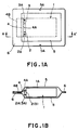
- FIG. 1A A replaceable ink cartridge and a package thereof in accordance with the present invention are illustrated in Fig. 1A and Fig. 1B.
- An ink-jet cartridge 1 comprises an ink outlet 2 and an air communicating port 3 which are sealed off by a seal member 4 just before using by the user after supplying from a supplier. Therefore, the seal member 4 cannot be removed by the time of connecting the cartridge 1 with a recording head.
- the seal member 4 is combined with a package 5, so that the seal member 4 is peeled off when the package 5 is pulled into pieces by force.
- the package 5 is hermetically sealed by welding its boundaries.
- each longitudinal boundary portion (peripheral portion 6) of the package 5 has a chipped portion 5A which are formed so as to avoid any influence on sealed portions when the package 5 is pulled into pieces by force at the chipped portion 5A.
- collar ribs 2A and 3A or so called ink outlet perpheral portion 2A and air communicating port peripheral portion 3A are formed, respectively.
- Each of these collar ribs 2A and 3A is in the shape of a cylinder.
- the collar ribs 2A and 3A have the same height in the same plane of the cartridge body 1A and they are arranged substantially along a longitudinal central line of that plane.
- the seal member 4 having a sufficient strength with respect to a stretch or the like, so that it is made of a flexible complex material comprising a single plastic film, a layered plastic films, or the like. It is also preferable that the seal member 4 has at least two weldable parts for connecting with end surfaces of the collar ribs 2A and 3A, respectively.
- Fig. 1B shows a connected part among the seal member 4, the package 5, and the collar rib 2A (3A).
- a welding between the end of the collar rib 2A (3A) and a weldable seal portion 4A formed on one side of the seal member 4 makes it possible to seal the ink outlet 2 and the air communicating port 4 to keep ink inside without a chance to leak.
- Another end 4B of the seal member 4 is bent and extended to the edge of the package 5, so that the former is supported by the latter.
- the package 5 is provided as in the form of a bag made up of two sheets of paper-like material, where the ink cartridge 4 sealed with the seal member 4 is held in after the sealing. In this case, the extended portion 4B of the seal member 4 is fixed with the peripheral portion 6 of the package 5.
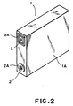
- FIG. 2 An external appearance of the ink cartridge itself is shown in Fig. 2.
- an external form of the collar rib 2A of the ink outlet 2 is smaller than that of the collar rib 3A of the air communicating port 3.
- the collar rib 2A is thicker than the collar rib 3A.
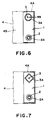
- Figs. 3A to 3C are illustrations for explaining the construction of the ink outlet 2, the air communicating port 3, and their peripheral portions (the collar ribs 2A and 3A) of the ink cartridge 1 shown in Fig. 2.
- Fig. 3A is a front view
- Figs. 3B and 3C are cross sectional views taken on lines A-A and B-B of Fig. 3A, respectively.
- the collar rib 2A around the ink outlet 2 is in the shape of cylinder being concentric with the ink outlet 2 while the collar rib 3A around the air communicating port 3 is in the shape of square. Furthermore, an opening of the collar rib 3A is larger than that of the collar rib 2A while a thickness WA of the former is smaller than a thickness WB of the latter so as to obtain the relation of:
- the above construction of the ink cartridge is for physically communicating the air communicating port 3 with the atmosphere prior to open the ink outlet 2. Another embodiment of such construction will be explained later.
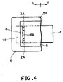
- Figs 4, and 5A-5B are illustrations for explaining the way of sealing off the replaceable ink cartridge 1 constructed as described above.
- Fig. 4 illustrates a condition of tearing the package 5A of Fig. 1 from the cutting portion 5A. That is, the package 5A is pulled into two pieces: one having a part of peripheral portion 6 connecting with the edge 4B of the seal member (a part indicated by an arrow L of the figure, hereafter referred as a left part); and the other having a part of peripheral portion 6 without the edge 4B of the seal member 4 (a part indicated by an arrow R of the figure, hereinafter referred as a right part).
- Figs. 5A and 5B indicate that the steps of tearing the seal member from the ink outlet 2 and the air communicating port 3 after the condition shown in Fig. 4. to leave them open.
- the collar rib 3A of the air communicating port 3 receives a force of the strip movement at first because its external form is larger than that of the collar rib 2A of the ink outlet 2. Consequently the seal member 4 starts to strip off from the collar rib 3A at first (Fig. 5B).
- an external form of the collar rib 2A is smaller than that of the collar rib 3A so that the collar rib 2A does not receive the force of the strip movement (Fig. 5A).
- the thickness WB of the collar rib 3A is smaller than the thickness WA of the collar rib 2A so that the air communicating port 3 is able to communicate with the atmosphere just after the beginning of the strip movement.
- it is difficult to make a communication between the ink outlet 2 and the atmosphere just after the beginning of the strip movement because of the collar rib 2A has a larger thickness compared with that of the collar rib 3A.
- the strip movement of the seal member 4 permits an unseal of the air communicating port 3 prior to an unseal of the ink outlet 2.
- collar ribs 2A and 3A are uniformly formed around the ink outlet 2 and the air communicating port 3, respectively, so as to have a constant thickness.
- WB ⁇ WA it is also possible to keep the relation of WB ⁇ WA only for at least each part of these collar ribs, where the stripping force is initially effected.
- effects of the present invention can be also obtained by forming the collar rib 3A of the air communicating port 3 as a cylindrical one with a thickness WB' satisfying the inequality of WB' ⁇ WA.
- the collar rib 3A of the air communicating port 3 so as to form the collar rib 3A as a square tube having a corner being positioned at the side of the seal member's edge 4B. That is, the corner of the square is positioned toward the direction of stripping the seal member for more easily strip movement.
- the collar rib 3A in the shape of star-like tube having rounder protruded portions and one of them is positioned at the side of the seal member's edge 4B.
- a thickness of the collar rib 3A formed on each ink cartridge is smaller than that of the collar rib 2A around each ink outlet 2. According to these constructions, the air communicating port 3 can be sealed off at first, prior to the ink outlet 2.
- the collar rib 3A around the air communicating port and the collar rib 2A around the ink outlet can be formed and positioned in any of several possible ways, for example an opening of the collar rib 3A around the air communicating port is larger than that of the collar rib 2A around the ink outlet; a thickness of the collar rib 3A is smaller than that of the collar rib 2A; and at least a part of the peripheral portion of the collar rib 3A is positioned at a front of the collar rib 2A when the seal member 4 is removed off.
- the construction cannot be restricted by the above description but it can be formed and positioned in every way under the conditions described above.
- the peripheral portions of the ink outlet and the air communicating port are constructed so as to open the air communicating port at first in accordance with the strip movement of the seal member.
- the second preferred embodiment on the other hand, another construction for more appropriate propagation of the force of stripping the seal member onto a sealed portion between the seal member and the air communicating port (or the ink outlet) will be described in detail.
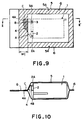
- Fig. 9 is a schematic diagram for explaining each construction of a replaceable ink cartridge, a package for covering the cartridge, and a seal member for sealing an ink inlet, and an air communicating port of the cartridge in accordance with the present invention.
- Fig. 10 is a sectional view taken substantially along the lines II-II' of Fig. 9.
- reference numeral 1 denotes an ink cartridge body (hereinafter, referred as a body), 2 denotes the ink outlet, 3 denotes the air communicating port, 4 denotes the seal member sealing the ink outlet 2 and the air communicating port 3, and 5 denotes the package for packing the whole body 1.
- the body 1 is provided as a container for storing ink.
- the body 1 comprises a housing portion for holding a negative-pressure generating member and an ink storage portion for storing ink.
- the negative-pressure generating member absorbs ink to hold it inside and communicates with the ink outlet 2 and the air communicating port 3.
- a cylindrical collar rib 2A is formed around an opening of the ink outlet 2, and also a tubular collar rib 3A having a cross section shaped like a parallelogram is formed around an opening of the air communicating port 3.
- a diameter of the opening of the ink outlet 2 is almost the same size as that of an inner peripheral surface of the collar rib 2A but larger than that of the air communicating port 3.
- a thickness WA of the collar rib 2A is larger than a thickness WB of the collar rib 3A.
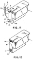
- the seal member is made of a flexible barrier material having a sufficient strength with respect to forces to be applied on the seal member, such as a force of pulling the seal member. Therefore, the material is, for example a complex material consisting of a plurality of layers of plastic films or a single layered plastic film. It is also preferable that the material shows the properties of welding with end surfaces of the collar ribs 2A and 3A.
- the seal member according to this embodiment, as shown in Fig. 11, is in the form of a flat trapezoid having a short upper side 4A and a long under side 4B.
- the seal member 4 is provided in that its under side 4B is located over the collar ribs 2A and 3A and an adjacent area of the under side 4B is welded with each end surface of these ribs 2A and 3A. Consequently, the ink outlet 2 and the air communicating port 3 are sealed.
- a portion responsible for sealing the ink outlet as a first seal portion A
- another portion responsible for sealing the air communicating port 3 as a second seal portion B.
- the first and second seal portions A, B have to only seal the ink outlet 2 and the air communicating port 3 so as to endure expanding pressures of ink and air in the body 1 and to prevent a vaporization of ink in the body 1.
- the seal member by welding but also by one of every connecting methods including a squeeze and a bonding.
- the upper side 4A of the seal member 4 is on the side of the second seal portion B nearer than the first seal portion A (i.e., it is on an upper area of Fig. 11) .
- an area in close proximity to the upper side 4A i.e., a slanting-lined portion C in Fig. 11
- a handling portion we refer the slanting-lined portion C in the figure as a handling portion.
- the package 5 is in the form of a bag for covering the entire body 1 of the ink cartridge.
- a peripheral portion 6 of the package 5 is welded so as to form the bag.
- the handling portion C of the seal member 4 is also welded in the peripheral portion 6.
- the package 5 may be connected with the handling portion C of the seal member 4 by the way of contact welding, pressure welding, solvent welding, sticking with an adhesive, or the like.
- a material of the package 5 may be the same as that of the seal member or one selected from any materials to be used in the field of packaging, such as paper and a plastic sheet.
- a welding layer of the seal member 4 and a welding layer of the package 5 are welded together by applying heat with pressure. Under the state that the body 4 is packed in the package 5, as shown in Fig. 10, there is a curved portion between the upper end 4A and the under end 4B of the seal member 4.
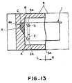
- Fig. 13 and Figs. 14A to 14C are schematic diagrams for illustrating the procedure of opening the replaceable ink cartridge.
- the process including the step of cutting the package 5 into two pieces from the cutting portion 5A to remove the part indicated by an arrow R in the figure (i.e., a left half in the figure). That is, the part indicated by an arrow L (i.e., a right half in the figure, which is a part responsible for preventing a scatter of ink) remains while the left half is removed.
- a part of the peripheral portion of the package 5, which is above a cutting line (not shown,) is cut down to make a cutting portion 5A to make the cutting more easily and perfectly.
- a perforation along the cutting line Preferably, a peel tape or the line may be provided along the cutting line on the package 5. In this case, the package can be separated into two parts along the cutting line by pulling the peel tape.
- Fig. 14A illustrates the package 5 where the right half are removed. In the figure, the remained left half of the package 5 is indicated by a two-dot slash line.
- the operator After removing the right half of the package 5, the operator takes an end of the left half of the package with his or her fingers and pulls it toward the side away from the body 1 (e.g., a direction of an arrow P in Fig. 14A). A force of the pulling operation is applied on the handling portion C of the seal member 4, resulting that the seal member is stripped off from the collar ribs 2A and 3A, following with a separation of the left half of the package 5 from the body 1, as shown in Fig. 14B and Fig. 14C.
- a force (a peel force) in the direction of an arrow P to be applied to the handling portion C tends to propagate toward the second seal portion B rather than the first seal portion A. That is, as shown in Fig. 11, the length L2 between the handling portion C and the second seal portion B is shorter than the length L1 between the handling portion C and the first seal portion A.
- the shortest length L2 between the handling portion C and the second seal portion B is shorter than the shortest length L1 between the handling portion C and the first seal portion A in consideration of the facts that the handling portion C is elongated along the upper end portion 4A and each operator picks at any positions and pulls the handling portion C toward any directions as his or her pleases.
- the second seal portion B is peeled off from the collar rib 3A at first before the first seal portion A is peeled off from the collar rib 2A (Fig. 14B).
- the air communicating port 3 can be opened before the ink outlet 2, resulting that it prevents a scattering of ink to be occurred when the ink outlet 3 is opened at first.
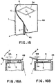
- Fig. 14A-C, Fig. 15, and Fig. 16B illustrate the beginning of sealing off the air communicating port 3, while Fig. 14C and Fig. 16A illustrate the beginning of sealing off the ink outlet 2.
- the left half of the package 5 is omitted to illustrate but it covers the ink outlet 2 and the air communicating port 3 during the period of pulling out the seal member 5. Therefore, it is able to receive leaked ink to keep user's hands and clothes clean.
- the collar rib 3A is formed as a cylindrical projection with a cross section in the shape of a parallelogram in a plane view.
- An acute angle (i.e., an angle portion E in Fig. 15) of the parallelogram is corresponded to a start position to peel the second seal portion B.
- the angle portion E receives a concentrated stress of the peel force being applied on the handling portion C of the seal member 4 for peeling the second seal portion B more easily. Therefore, it make sure that the air communicating port 3 is opened at first.
- a stress of the peel force may be concentrated on the an peeling start area of the second seal portion B by forming a side extending along the direction of peeling the second seal portion on a peripheral of a welded face between the opening of the air communicating port 3 and the second seal portion B.
- a thickness WB of the collar rib 3B is smaller than a thickness WA of the collar rib 2A, so that a strength of a welded face between the collar rib 3A and the second seal portion B is frailer than that of a welded face between the collar rib 2A and the first seal portion A. Therefore, it make more sure that the air communicating port 3 is opened at first.
- the seal member 5 of the present embodiment has a trapezoidal shaped flat surface.
- a short upper side 4A of the trapezoid is positioned in the welded portion 6 of the of the package 5.
- a width of the welded portion 6 is indicated as WC.
- the area neighboring the upper side is provided as the handling portion C, and thus the step of binding the seal member 4 with the package can be performed during the process of welding a package material into a bag-like form without interrupting the operator's manipulation.
- a length L1 from the collar rib 2A to the handling portion C is longer than a length L2 from the collar rib 3A to the handling portion C (i.e., L1 > L2).
- the inequality of L1 > L2 is realized by a relative positions of the ink outlet 2, the air communicating port 3, and the connected site between the seal member 4 and the package 5. Therefore, the seal member 4 and the package 5 do not limited in the shape or the like illustrated in the figures but it takes every shapes or the like within the limit of satisfying the above inequality. That is, it only requires that the handling portion C corresponding to the joint area between the seal member 4 and the package 5 is on the air communicating port's side rather than the ink outlet's side.
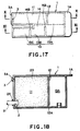
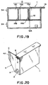
- Fig. 17 and Fig. 19 illustrate an inner structure of the ink jet cartridge's body 1 in accordance with the present invention.
- the body 1 has an ink outlet 2 to be connected with an ink jet recording head and an air communicating port 3 formed above the ink outlet 2. Also, the body comprises: a holding section 11 for holding a negative-pressure generating member 20 by which ink is absorbed and held; and an ink storage section 13 communicating with the holding section 11 by means of a space under the rib 12. Furthermore, the ink storage section 13 comprises a first ink storage portion 13A, a second ink storage portion 13B communicated with the first portion 13A through a communicating path 14A, and a third ink storage portion 13C communicated with the second portion 13B through a communicating path 14B.
- the ink storage section 13 has a comparatively large capacity for storing ink, so that the body 1 can be preferably used for storing a black ink to be more frequently consumed than other color inks in the process of forming a color image by the recording apparatus.
- a half part of an inner bottom's surface of the ink storage portion 3A on the side of line XI-XI in Fig. 17 and inner bottom's surfaces of the ink storage portions 3B and 3C are located over the level of the ink outlet 2 at a predetermined distance.
- a material having a porous structure such as urethane foam, makes up the negative-pressure generating member 20.
- reference numeral denotes a pick-up portion for picking up in user's fingers to detach the cartridge's body 1 from the recording head.
- the holding section 11 for holding the negative-pressure generating member In the holding section 11 for holding the negative-pressure generating member, a gradation of ink can be observed. For smoothly supplying the ink to the ink jet recording head, that is, a large amount of the ink is concentrated at the ink outlet's side while the ink cannot be observed at the side of the air communicating port. For this reason, it is preferable to open the air communicating port 3 at first. When the ink outlet 2 is sealed off at first, on the other hand, there tends to be a scattering of ink from the ink outlet 2 to the outside.
- an ink inlet tube 31 of the ink jet recording head is inserted into the ink outlet 2 of the body 1 to make a press-contact between the ink inlet tube 31 and the negative-pressure generating member 20, as shown in Fig. 18.
- an opening of the ink inlet tube 31 may have a filter (not shown in the figure) through which ink is passed in order to separate the fluid from suspended particulate matter.
- the ink jet recording apparatus is switched on to perform an image formation, in which an eject ion of ink from each orifice of the ink jet recording head leads to generate a force to absorb ink in the holding section 11.
- the absorbing force draws the ink into the negative-pressure generating member 11 from the ink storage section 13 through a gap portion 12A under a rib 12.
- the passed ink is further introduced into the ink inlet tube 30 and supplied to the ink jet recording head. Consequently, an inner pressure of the body 13 where all of the openings except the gap 12A are closed is decreased, resulting that a pressure difference between the ink storage section 13 and the negative-pressure generating member holding section 11 is generated.
- a supply of ink is also continued with an increase of the above pressure difference.
- the ink storage section 13 receives the flesh air passing through the negative-pressure generating member 20 and the gap portion 12A under the rib 12 because the negative-pressure holding section 11 communicates with the atmosphere through the air communicating port 11. Therefore, it results in a cancellation of the above difference between the ink storage section 13 and the negative-pressure generating member 11.
- the above steps can be repeated to supply ink, more smoothly.
- a whole amount of ink in the ink storage section 13 can be used up, except that an extremely small amount of ink adheres on each wall surface of first and second ink storage portions 13A and 13B. Therefore, the high efficiency of using ink can be attained.
- the negative-pressure generating member 20 exerts a force of capillary phenomenon or the like, so that a leakage of ink from the ink jet recording head can be prevented.
- the seal member 4 may be effectively applied on the ink cartridge that have the same appearance as of the first embodiment as shown in Fig 20.
- a configuration of the seal member 4 may be in the shape of character "L" in a plane view thereof.
- the seal member 4 has a first side area corresponding to a vertical side of the "L” and a second side area corresponding to a horizontal side thereof.
- the first seal portion A is defined on a top side of the first side area
- the second seal portion B is defined on a bottom side of the first side area, where a cross point of two side areas
- the handling portion C to be welded with the package 5 is formed at an end of the second side area, far from the first side area. Therefore, a peel force being applied on the handling portion C is transmitted to the second seal portion B rather than the first one A, so that the air communicating port can be opened at first prior to open the ink outlet 2.
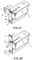
- FIG. 22 Another shape of the seal member 4 is shown in Fig. 22.
- the seal member 4 is in the shape of a linear belt with an end portion provided as a handling portion C.
- First and second seal portions A and B are formed in line on the seal member 4 in that the second seal portion B is on the side of the handling portion C and the first seal portion A is on the opposite side thereof. Therefore, the seal member 4 is removed from the second seal portion B at first by a peel force being applied on the handling portion C and then it is removed from the first seal member A.
- a shape of the seal member 4 may be optionally determined on condition that the shape thereof is for easily transmitting a peel force applied on the handling portion C to the second seal portion B rather than the first seal portion A.
- the package 5 is not indispensable because the seal member 4 only requires a means for applying a peel force on the handling portion 4 by the user.
- the handling portion C is like a tongue protruded outwardly from the ink outlet 2 and the air communicating port 3 formed on a surface of the body 1, so that it is an inevitable consequence that only the handling portion C is specified as the place where a peel force is applied effectively.
- the package 5 it is no need to connect the package 5 and the handling portion C.
- the air communicating port 3 can be opened prior to open the ink outlet 2 by peeling the second seal portion B prior to peel the first seal portion A under the condition that a force standing up to the peeling between an opening of the air communicating port 3 and the second seal portion B is smaller than that of between an opening of the ink outlet 2 and the first seal portion A. It is noted that this kind of peeling operation can be occurred in spite that these peeling portions receive almost the same degree of the peel force at the same time.
- a thickness WB of the collar rib 3A may be limited so as to be smaller than a thickness WA of the collar rib 2A (see Figs. 16A and 16B), or a stress of the peel force may be concentrated on an edge portion E (see Fig. 15) corresponding to a position of starting the peeling operation in the second seal portion B.
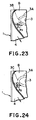
- Fig. 23 is an enlarged partial diagrammatic view of an exemplified configuration of a sealed area formed between a second seal portion B of a seal member 4 and an opening of an air communicating port 3.
- a portion of the color rib 3A (the left portion thereof in Fig. 23) corresponding to the starting position P1 of peeling operation comprises a side portion 3B being elongated in the direction (i.e., a vertical direction in Fig. 23) perpendicular to the direction of peeling the seal member 4.
- a peel resistance at the peel-starting position P1 of the second seal portion B becomes greater than a peel resistance at the position P2 for opening the air communicating port 3, resulting that a carelessness peel of the seal member 4 can be perfectly prevented during the process of handling the ink cartridge.
- a peel resistance of the second seal portion B at the peel starting position P1 is smaller than that of the first seal portion A at the peel starting position P2, furthermore, it is possible to open the air communicating port 3 prior to open the ink outlet 2 by sealing off the second seal portion B at the peel-starting position P1 at first in spite that almost the same degrees of peel forces are applied on the first and second seal portions A, B at the peel-starting positions P1, P2, respectively.
- Fig. 24 is an enlarged partial diagrammatic view of an exemplified configuration of a sealed area formed between a second seal portion B of a seal member 4 and an opening of an air communicating port 3.
- a portion of the color rib 3A corresponding to the starting position P1 of peeling operation is formed as a curved portion 3C to prevent a carelessness peel of the seal member 4 at an area with length L defined as a distance between a peel-starting position P1 and a opening-starting position P2.
- the maximum of the peel resistance at the area with length L may be smaller than that the peel resistance at the peel-starting position of the first seal portion A.
- a configuration or the like of the rib 3A of the air communicating port 3 is different from that of the rib 2A of the ink outlet 2.
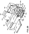
- the ink jet cartridge as described above can be installed in a recording apparatus as shown in Fig. 25 to perform a recording of images.
- Fig. 25 is a perspective view of an ink jet recording apparatus having a replaceable ink cartridge in accordance with the present invention.
- reference numeral 101 denotes a printer
- 102 denotes an operation panel portion provided on a front side of a housing's top of the printer
- 103 denotes a paper-feed cassette placed in an opening formed on a front face of the housing
- 104 denotes a sheet of paper (i.e., a recording medium) moved from the paper-feed cassette 103
- 105 denotes an expelled paper tray to receive a sheet of paper thrown out from the housing after passing through a paper-feed path in the printer 101
- 106 denotes a body cover in the shape of character "L" in a cross section thereof.
- the body cover 106 is responsible for covering an opening 107 formed on a right front of the above housing.
- the body cover 106 is jointed with opposite inner sides of the opening 107 by means of a pair of hinges that allow the pivoting of the body cover 106.
- a carriage 110 is mounted on a guide or the like (not shown) so as to move back and forth in the direction along a width of the paper passing through the paper-feed path (i.e., the longitudinal direction of the guide or the like).
- the carriage 110 is constituted by a horizontal stage 110a being placed in a horizontal position by the guide or the like; an opening (not shown) formed on the stage 110a and located in proximity to the guide, in which ink jet recording heads are installed; a cartridge garage 110b for accommodating ink cartridges 1Y, 1M, 1C, and 1Bk which are placed on the stage 11a in the front area of the opening; a cartridge holder 110c for holding these ink cartridges to prevent their dislocations.
- the above stage 110a has a rear end portion to be slide-ably supported by the above guide and a front end portion to be placed on a guide plate (not shown) by its hidden side.
- the guide plate may be of having a mechanism as a paper-hold member for preventing a rise of a sheet of paper to the surface in the paper-feed path or of having another mechanism of lifting one side of the stage with respect to the guide in accordance with a thickness of the paper.
- the ink jet recording head (not shown) is installed in the opening of the above stage 110a in a manner that ink-ejection orifices of the head are faced in the downward direction.
- the above cartridge garage 110b comprises a through hole formed therethrough in the front and behind direction and hollows 110d for receiving projections (i.e., hooks) 110e of the cartridge holder 110c on opposite outside portions, respectively.
- the front end portion of the stage 110a is jointed with the cartridge holder 110c by means of a pair of hinges 116 that allow the pivoting of the 110c.
- a distance between the front of the garage 110b and the hinge 116 is determined with a consideration of the dimensions or the like of each portion of the ink cartridges 1Y, 1M, 1C, and 1Bk to be protruded from the position of the front of the garage 110b at the time of these cartridges are installed.
- the cartridge holder 110c is shaped like a square plate and comprises a pair of hooks 110e to be engaged in holes 110d formed on the above garage 110C at the time of closing the holder 110c. As shown in the figure, each hook is provided on an upper edge of the holder 110c, which is at the opposite position of the hinged portion at the bottom.
- the cartridge holder 110c further comprises a slit 120 on a plated surface thereof for firmly attaching to grip portions of the above ink cartridges 1Y, 1M, 1C, and 1Bk.
- the slit 120 is formed so as to satisfy appropriate conditions (i.e., position, dimensions, shape, and the like) corresponding to the above grip portions.
Claims (15)
- Austauschbare Tintenkartusche, um mit einer Aufzeichnungseinrichtung abnehmbar verbunden zu sein für die Zufuhr von Tinte in die Aufzeichnungseinrichtung zum Aufzeichnen eines Bildes auf einem Aufzeichnungsmedium mit:einem Tintenkartuschenkörper (1) zum Lagern von Tinte,einem Tintenauslaß (2) und einem Luftverbindunganschluß (3), die an dem Tintenkartuschenkörper (1) ausgebildet sind,einem Tintenauslaßumfangsabschnitt (2a), der um den Tintenauslaß (2) herum ausgebildet ist und sich von diesem nach außen erstreckt,einem Dichtungselement (4) zum abnehmbaren Dichten des Tintenauslaßumfangsabschnitts (2a) und des Luftverbindungsanschlusses (3), wobei das Dichtungselement (4) durch Ablösen abnehmbar ist, wobei
der Luftverbindungsanschluß (3) von einem Luftverbindungsanschlußumfangsabschnitt (3a) umgeben ist, der sich von dem Verbindungsanschluß (3) nach außen erstreckt, um abnehmbar abgedichtet zu sein durch das Dichtungselement (4), wobei zumindest eine aus der relativen Dicke (WB), Form oder Größe des Luftverbindungsanschlußumfangsabschnitts (3a) bezüglich dem Tintenauslaßumfangsabschnitt (2a) oder Form des Dichtungselements (4) derart vorgesehen ist, daß eine Ablösekraft zum Entfernen des Dichtungselements (4) von dem Luftverbindungsanschlußumfangsabschnitt (3a) in einer Ablöserichtung kleiner ist als eine Ablösekraft zum Entfernen des Dichtungselements (4) von dem Tintenauslaßumfangsabschnitt (2a), so daß der Luftverbindungsanschluß (3) vor dem Öffnen des Tintenauslasses (2) geöffnet wird. - Tintenkartusche nach Anspruch 1, dadurch gekennzeichnet, daß der Tintenauslaßumfangsabschnitt (2a) und der Luftverbindungsanschlußumfangsabschnitt (3a) Bundrippen sind, die die jeweiligen Öffnungen umgeben, wobei die Dicke (WP) der Bundrippe des Luftverbindungsanschlußumfangsabschnitts (3A) kleiner ist als eine Dicke (WA) einer Bundrippe des Tintenauslaßumfangsabschnitts (2A).
- Tintenkartusche nach Anspruch 1 oder 2, dadurch gekennzeichnet, daß der Luftverbindungsanschlußumfangsabschnitt (3A) eine polygonische Außenform hat und eine Ecke hat, die der Ablöserichtung zugewandt ist.
- Tintenkartusche nach Anspruch 3, dadurch gekennzeichnet, daß der Luftverbindungsanschlußumfangsabschnitt (3A) eine quadratförmige Außenform hat, wobei seine Ecke der Ablöserichtung mit einem rechten Winkel zugewandt ist.
- Tintenkartusche nach Anspruch 3, dadurch gekennzeichnet, daß der Luftverbindungsanschlußumfangsabschnitt (3A) eine sternenartige Außenform hat, wobei seine Ecke der Ablöserichtung mit einem spitzen Winkel zugewandt ist.
- Tintenkartusche nach Anspruch 3, dadurch gekennzeichnet, daß der Luftverbindungsanschlußumfangsabschnitt (3A) eine parallelogrammförmige Außenform hat, wobei seine Ecke der Ablöserichtung mit einem spitzen Winkel zugewandt ist.
- Tintenkartusche nach einem der vorangegangenen Ansprüche, dadurch gekennzeichnet, daß ein Innendurchmesser der Bundrippe des Luftverbindungsanschlußumfangsabschnitts (3A) größer ist als der Innendurchmesser der Bundrippe des Tintenauslaßumfangsabschnitts (2A).
- Tintenkartusche nach Anspruch 1, dadurch gekennzeichnet, daß eine äußere Kante des Luftverbindungsanschlußumfangsabschnitts (3A) vor einer äußeren Kante des Tintenauslaßumfangsabschnitts (2A) ist in einer vorgegebenen Richtung des Ablösens des Dichtungselements (4).
- Tintenkartusche nach Anspruch 1, dadurch gekennzeichnet, daß eine innere Kante des Luftverbindungsanschlußumfangsabschnitts (3A) vor einer inneren Kante des Tintenauslaßumfangsabschnitts (2A) ist in einer vorgegebenen Richtung des Ablösens des Dichtungselementes (4).
- Tintenkartusche nach einem der vorangegangenen Ansprüche, dadurch gekennzeichnet, daß das Dichtungselement (4) einen ersten Dichtungsabschnitt (A) hat zum Abdichten der Öffnung des Tintenauslasses (2) und einen zweiten Dichtungsabschnitt (B) zum Abdichten der Öffnung des Luftverbindungsanschlusses (3) und einen Handhabungsabschnitt (C) zum Ablösen des Dichtungselements (4).
- Tintenkartusche nach Anspuch 10, dadurch gekennzeichnet, daß eine Startposition zum Ablösen des Dichtungselements (4) von dem Umfangsabschnitt (3A) um den Luftverbindungsanschluß (3) herum vor einer Startposition zum Ablösen des Dichtungselements (4) von dem Umfangsabschnitt (2A) um den Tintenauslaß (2) herum in eine Richtung des Ablösens des Dichtungselements (4) ist.
- Tintenkartusche nach Anspruch 10, dadurch gekennzeichnet, daß eine Länge des zweiten Dichtungsabschnitts (B) und des Handhabungsabschnitts (C) kürzer ist als eine Länge zwischen dem ersten Dichtungsabschnitt (A) und dem Handhabungsabschnitt (C) bei dem Dichtungselement (4).
- Tintenkartusche nach einem der vorangegangenen Ansprüche, die desweiteren eine Packung (5) zum Verpacken des Tintenkartuschenkörpers (1) aufweist.
- Tintenkartusche nach Anspruch 13, dadurch gekennzeichnet, daß das Dichtungselement (4) an der Packung (5) fixiert ist, so daß das Dichtungselement (4) abgelöst wird beim Entfernen der Verpackung (5) von dem Kartuschenkörper (1).
- Tintenkartusche nach einem der vorangegangenen Ansprüche, dadurch gekennzeichnet, daß das Dichtungselement (4) an den Bundrippen und/oder der Packung (5) durch Schweißen fixiert ist.
Applications Claiming Priority (6)
| Application Number | Priority Date | Filing Date | Title |
|---|---|---|---|
| JP11927994A JP3168116B2 (ja) | 1994-05-31 | 1994-05-31 | 交換型インクカートリッジ |
| JP11927994 | 1994-05-31 | ||
| JP119279/94 | 1994-05-31 | ||
| JP159045/94 | 1994-07-11 | ||
| JP15904594 | 1994-07-11 | ||
| JP15904594A JP3152839B2 (ja) | 1994-07-11 | 1994-07-11 | 交換型インクカートリッジ、パッケージ、およびパッケージの開封方法 |
Publications (2)
| Publication Number | Publication Date |
|---|---|
| EP0685340A1 EP0685340A1 (de) | 1995-12-06 |
| EP0685340B1 true EP0685340B1 (de) | 1999-08-18 |
Family
ID=26457046
Family Applications (1)
| Application Number | Title | Priority Date | Filing Date |
|---|---|---|---|
| EP95108183A Expired - Lifetime EP0685340B1 (de) | 1994-05-31 | 1995-05-29 | Austauschbare Tintenpatrone mit Verschlussstruktur |
Country Status (3)
| Country | Link |
|---|---|
| US (2) | US6164769A (de) |
| EP (1) | EP0685340B1 (de) |
| DE (1) | DE69511461T2 (de) |
Cited By (1)
| Publication number | Priority date | Publication date | Assignee | Title |
|---|---|---|---|---|
| EP1559559A2 (de) | 2004-01-29 | 2005-08-03 | Pelikan Hardcopy Production AG | Tintenpatrone |
Families Citing this family (42)
| Publication number | Priority date | Publication date | Assignee | Title |
|---|---|---|---|---|
| US5956057A (en) | 1996-08-30 | 1999-09-21 | Hewlett-Packard Company | Ink container having electronic and mechanical features enabling plug compatibility between multiple supply sizes |
| US5953030A (en) * | 1995-04-24 | 1999-09-14 | Canon Kabushiki Kaisha | Ink container with improved air venting structure |
| JP3327807B2 (ja) * | 1996-03-01 | 2002-09-24 | キヤノン株式会社 | インクタンクの包装構造および該包装構造が施されるインクタンク |
| US5847735A (en) * | 1996-04-26 | 1998-12-08 | Pelikan Produktions Ag | Ink cartridge for a printer |
| JPH10166610A (ja) * | 1996-12-17 | 1998-06-23 | Nec Niigata Ltd | インクカートリッジ |
| DE19707585A1 (de) * | 1997-02-26 | 1998-09-03 | Bosch Gmbh Robert | Gehäuse mit radarabsorbierenden Eigenschaften |
| JPH10250104A (ja) | 1997-03-12 | 1998-09-22 | Seiko Epson Corp | インクジェット式記録装置用インクカートリッジ、及びその製造方法 |
| JPH10258520A (ja) * | 1997-03-21 | 1998-09-29 | Brother Ind Ltd | 液体収納容器 |
| US6199973B1 (en) | 1997-09-03 | 2001-03-13 | Hewlett Packard Company | Storage container for inkjet cartridges having removable capping means and a method for storing inkjet cartridges |
| EP1300249B1 (de) * | 1998-03-30 | 2008-10-22 | Brother Kogyo Kabushiki Kaisha | Tintenpatrone und Verfahren zur Detektion der restlichen Tintenmenge |
| US6270207B1 (en) | 1998-03-30 | 2001-08-07 | Brother Kogyo Kabushiki Kaisha | Ink cartridge and remaining ink volume detection method |
| JP3278410B2 (ja) | 1998-05-11 | 2002-04-30 | キヤノン株式会社 | 液体収納容器、該容器の製造方法、該容器のパッケージ、該容器と記録ヘッドとを一体化したインクジェットヘッドカートリッジ及び液体吐出記録装置 |
| SG95595A1 (en) * | 1998-05-13 | 2003-04-23 | Seiko Epson Corp | Ink cartridge for ink-jet printing apparatus |
| AU761941B2 (en) * | 1999-01-30 | 2003-06-12 | Dynamic Cassette International Ltd. | Cartridge having removable part for opening an aperture |
| US7152965B2 (en) * | 2000-01-21 | 2006-12-26 | Seiko Epson Corporation | Ink cartridge, and ink-jet recording apparatus using the same |
| JP3774675B2 (ja) * | 2001-05-10 | 2006-05-17 | キヤノン株式会社 | パッケージ |
| US6764170B2 (en) * | 2001-06-14 | 2004-07-20 | Hewlett-Packard Development Company, L.P. | Removable label for sealing an ink-jet ink reservoir |
| US6464339B1 (en) * | 2001-10-25 | 2002-10-15 | Hewlett-Packard Company | Fluid interconnect port seal with lock-out tab |
| JP3919567B2 (ja) * | 2002-03-18 | 2007-05-30 | キヤノン株式会社 | 液体収納容器の包装構造およびその開封方法 |
| JP4250433B2 (ja) * | 2002-03-18 | 2009-04-08 | キヤノン株式会社 | 液体収納容器の包装構造およびその開封方法 |
| US7215903B2 (en) * | 2003-07-01 | 2007-05-08 | Brother Kogyo Kabushiki Kaisha | Cartridge and method for filling a consumable into the cartridge |
| JP4038683B2 (ja) * | 2003-10-10 | 2008-01-30 | 理想科学工業株式会社 | インク容器 |
| JP2005153506A (ja) * | 2003-11-07 | 2005-06-16 | Canon Finetech Inc | インクタンクパッケージおよびインクタンクパッケージの開封方法 |
| US7527366B2 (en) * | 2004-02-09 | 2009-05-05 | Nu-Kote International, Inc. | Seal member for ink jet container |
| US20050249519A1 (en) * | 2004-05-06 | 2005-11-10 | Rec & Assign | Cartridge for toner having removable seal |
| US7316471B2 (en) * | 2005-09-29 | 2008-01-08 | Brother Kogyo Kabushiki Kaishi | Ink cartridges |
| US20070246146A1 (en) * | 2006-04-19 | 2007-10-25 | Lexmark International, Inc. | Perforated and/or pointed sealing film for easy peel inkjet printhead and ink tank system applications |
| JP4332752B2 (ja) * | 2006-12-28 | 2009-09-16 | ブラザー工業株式会社 | インクカートリッジ |
| US7562972B2 (en) * | 2007-01-30 | 2009-07-21 | Brother Kogyo Kabushiki Kaisha | Ink cartridges having signal blocking portions |
| US8025378B2 (en) * | 2007-03-28 | 2011-09-27 | Brother Kogyo Kabushiki Kaisha | Ink cartridges |
| JP5007601B2 (ja) * | 2007-05-02 | 2012-08-22 | セイコーエプソン株式会社 | 液体収容容器におけるシール方法、液体収容容器の再生方法、液体収容容器 |
| US20090189942A1 (en) * | 2008-01-28 | 2009-07-30 | Price Brian G | Humidity controlled container for device including a liquid |
| US20090251514A1 (en) * | 2008-04-08 | 2009-10-08 | Static Control Components, Inc. | Universal ink cartridge seal |
| JP2010036457A (ja) * | 2008-08-05 | 2010-02-18 | Seiko Epson Corp | 液体容器、包装された液体容器及びその製造方法 |
| JP5948848B2 (ja) * | 2011-12-16 | 2016-07-06 | セイコーエプソン株式会社 | 液体収容体 |
| JP5929166B2 (ja) | 2011-12-22 | 2016-06-01 | ブラザー工業株式会社 | 印刷流体カートリッジ及び規制部材 |
| JP6241355B2 (ja) * | 2014-04-07 | 2017-12-06 | セイコーエプソン株式会社 | 液体供給ユニット用の保護部材 |
| US9132654B1 (en) | 2014-07-08 | 2015-09-15 | Funai Electric Co., Ltd. | Label for inkjet printhead |
| US9987849B2 (en) | 2015-08-21 | 2018-06-05 | Canon Kabushiki Kaisha | Liquid ejecting device |
| WO2017062007A1 (en) | 2015-10-08 | 2017-04-13 | Hewlett-Packard Development Company, L.P. | Printhead with removable printhead cover |
| US10035355B2 (en) * | 2016-10-13 | 2018-07-31 | Funai Electric Co., Ltd. | Packaging system for fluidic ejection cartridge with cartridge orientation control |
| CN112437904B (zh) | 2018-08-30 | 2023-09-08 | 惠普发展公司,有限责任合伙企业 | 打印再填充设备 |
Family Cites Families (14)
| Publication number | Priority date | Publication date | Assignee | Title |
|---|---|---|---|---|
| US3302818A (en) * | 1964-05-13 | 1967-02-07 | American Can Co | Container with easy-open end |
| US3441167A (en) * | 1967-10-20 | 1969-04-29 | American Can Co | Easy opening container |
| US4029033A (en) * | 1974-09-18 | 1977-06-14 | The Continental Group, Inc. | Convenience opening of containers for liquid products |
| US5231416A (en) * | 1988-11-09 | 1993-07-27 | Canon Kabushiki Kaisha | Container for ink jet head and recovering method of ink jet head using container |
| CA2025561C (en) * | 1989-09-18 | 1995-07-11 | Seiichiro Karita | Recording head with cover |
| ATE153917T1 (de) * | 1991-03-08 | 1997-06-15 | Canon Kk | Tintenstrahlaufzeichnungskopf und schützverfahren dafür |
| JP3192716B2 (ja) * | 1991-12-11 | 2001-07-30 | キヤノン株式会社 | インクカートリッジ用パッケージ |
| EP0627317B1 (de) * | 1993-05-25 | 1998-08-12 | Canon Kabushiki Kaisha | Verpackungsbehälter sowie Verfahren zu seiner Öffnung |
| JP3165281B2 (ja) | 1993-05-25 | 2001-05-14 | キヤノン株式会社 | 交換型インクジェット記録用インクカートリッジのパッケージおよびその開封方法 |
| DE4326564C2 (de) * | 1993-08-07 | 1998-05-28 | Eastman Kodak Co | Düsenabdeckung für einen Tintendruckkopf und Verfahren zum Aufbringen derselben |
| JP3253206B2 (ja) | 1994-01-14 | 2002-02-04 | キヤノン株式会社 | インク充填方法 |
| JPH07315437A (ja) | 1994-05-27 | 1995-12-05 | Canon Inc | 交換型インクカートリッジ |
| JPH08230205A (ja) * | 1995-02-28 | 1996-09-10 | Canon Inc | インクタンク保護方法及び部材とこれを有するインクタンク |
| US6168266B1 (en) * | 1995-09-29 | 2001-01-02 | Canon Kabushiki Kaisha | Ink tank cartridge, a manufacturing method thereof and a packaging structure of the ink tank cartridge |
-
1995
- 1995-05-29 DE DE69511461T patent/DE69511461T2/de not_active Expired - Fee Related
- 1995-05-29 EP EP95108183A patent/EP0685340B1/de not_active Expired - Lifetime
- 1995-05-30 US US08/453,148 patent/US6164769A/en not_active Expired - Lifetime
-
1999
- 1999-04-20 US US09/294,213 patent/US6382785B2/en not_active Expired - Fee Related
Cited By (1)
| Publication number | Priority date | Publication date | Assignee | Title |
|---|---|---|---|---|
| EP1559559A2 (de) | 2004-01-29 | 2005-08-03 | Pelikan Hardcopy Production AG | Tintenpatrone |
Also Published As
| Publication number | Publication date |
|---|---|
| US20010017640A1 (en) | 2001-08-30 |
| US6382785B2 (en) | 2002-05-07 |
| DE69511461D1 (de) | 1999-09-23 |
| DE69511461T2 (de) | 2000-04-13 |
| US6164769A (en) | 2000-12-26 |
| EP0685340A1 (de) | 1995-12-06 |
Similar Documents
| Publication | Publication Date | Title |
|---|---|---|
| EP0685340B1 (de) | Austauschbare Tintenpatrone mit Verschlussstruktur | |
| US8454143B2 (en) | Liquid container, methods of assembling or disassembling liquid container, and image forming apparatus | |
| US5131539A (en) | Package for ink jet cartridge | |
| US6848775B2 (en) | Ink cartridge for recording apparatus | |
| US5244092A (en) | Package for ink jet cartridge | |
| EP3225403B1 (de) | Tinte kartusche | |
| JP2000296626A (ja) | インク収納容器、その製造方法、及びインクカートリッジ | |
| EP0709211B1 (de) | Tintenbehälter mit ungefähr gleichgrossem porösen Körper | |
| EP1281529B1 (de) | Geometrische Merkmale zur Minimierung der Freitinte in einer Tintenversorgungsflüssigkeitsverbindung | |
| JP4669159B2 (ja) | インク供給装置、インク供給方法、および記録装置 | |
| JP3224971B2 (ja) | インクカートリッジ | |
| KR100503082B1 (ko) | 잉크젯 프린터용 잉크 카트리지 | |
| JP3202560B2 (ja) | インクカートリッジ | |
| US20230278341A1 (en) | Storage device and liquid ejection apparatus | |
| JPH0825640A (ja) | 交換型インクカートリッジ | |
| US11760098B2 (en) | Liquid discharge apparatus | |
| JPH11342622A (ja) | 液体収納容器、インクジェットヘッドカートリッジ、液体収納容器およびインクジェットヘッドカートリッジの分解方法 | |
| JPH07137277A (ja) | インク収容体の包装部材 | |
| JP3126398B2 (ja) | インクジェット記録ヘッド | |
| JPH0825644A (ja) | インクタンクおよび該タンクを用いたインクジェット装置 | |
| JP3118217B2 (ja) | 記録ヘッドの保管方法、記録ヘッド用キャップ、インクジェットカートリッジの保管方法及び使用時取り扱い方法 | |
| JPH11342625A (ja) | インクジェット記録装置 | |
| JPH0760978A (ja) | 交換型インクジェット用インクカートリッジ | |
| KR100234501B1 (ko) | 잉크 탱크 패키지 용기 | |
| JPH10258519A (ja) | インクカートリッジ |
Legal Events
| Date | Code | Title | Description |
|---|---|---|---|
| PUAI | Public reference made under article 153(3) epc to a published international application that has entered the european phase |
Free format text: ORIGINAL CODE: 0009012 |
|
| AK | Designated contracting states |
Kind code of ref document: A1 Designated state(s): DE FR GB IT |
|
| 17P | Request for examination filed |
Effective date: 19960415 |
|
| 17Q | First examination report despatched |
Effective date: 19970124 |
|
| GRAG | Despatch of communication of intention to grant |
Free format text: ORIGINAL CODE: EPIDOS AGRA |
|
| GRAG | Despatch of communication of intention to grant |
Free format text: ORIGINAL CODE: EPIDOS AGRA |
|
| GRAH | Despatch of communication of intention to grant a patent |
Free format text: ORIGINAL CODE: EPIDOS IGRA |
|
| GRAH | Despatch of communication of intention to grant a patent |
Free format text: ORIGINAL CODE: EPIDOS IGRA |
|
| GRAA | (expected) grant |
Free format text: ORIGINAL CODE: 0009210 |
|
| AK | Designated contracting states |
Kind code of ref document: B1 Designated state(s): DE FR GB IT |
|
| REF | Corresponds to: |
Ref document number: 69511461 Country of ref document: DE Date of ref document: 19990923 |
|
| ITF | It: translation for a ep patent filed |
Owner name: SOCIETA' ITALIANA BREVETTI S.P.A. |
|
| ET | Fr: translation filed | ||
| PLBE | No opposition filed within time limit |
Free format text: ORIGINAL CODE: 0009261 |
|
| STAA | Information on the status of an ep patent application or granted ep patent |
Free format text: STATUS: NO OPPOSITION FILED WITHIN TIME LIMIT |
|
| 26N | No opposition filed | ||
| REG | Reference to a national code |
Ref country code: GB Ref legal event code: IF02 |
|
| PGFP | Annual fee paid to national office [announced via postgrant information from national office to epo] |
Ref country code: DE Payment date: 20070524 Year of fee payment: 13 |
|
| PGFP | Annual fee paid to national office [announced via postgrant information from national office to epo] |
Ref country code: GB Payment date: 20070523 Year of fee payment: 13 |
|
| PGFP | Annual fee paid to national office [announced via postgrant information from national office to epo] |
Ref country code: IT Payment date: 20070514 Year of fee payment: 13 |
|
| PGFP | Annual fee paid to national office [announced via postgrant information from national office to epo] |
Ref country code: FR Payment date: 20070510 Year of fee payment: 13 |
|
| GBPC | Gb: european patent ceased through non-payment of renewal fee |
Effective date: 20080529 |
|
| REG | Reference to a national code |
Ref country code: FR Ref legal event code: ST Effective date: 20090119 |
|
| PG25 | Lapsed in a contracting state [announced via postgrant information from national office to epo] |
Ref country code: FR Free format text: LAPSE BECAUSE OF NON-PAYMENT OF DUE FEES Effective date: 20080602 Ref country code: DE Free format text: LAPSE BECAUSE OF NON-PAYMENT OF DUE FEES Effective date: 20081202 |
|
| PG25 | Lapsed in a contracting state [announced via postgrant information from national office to epo] |
Ref country code: GB Free format text: LAPSE BECAUSE OF NON-PAYMENT OF DUE FEES Effective date: 20080529 |
|
| PG25 | Lapsed in a contracting state [announced via postgrant information from national office to epo] |
Ref country code: IT Free format text: LAPSE BECAUSE OF NON-PAYMENT OF DUE FEES Effective date: 20080529 |