EP1559559A2 - Tintenpatrone - Google Patents
Tintenpatrone Download PDFInfo
- Publication number
- EP1559559A2 EP1559559A2 EP05001789A EP05001789A EP1559559A2 EP 1559559 A2 EP1559559 A2 EP 1559559A2 EP 05001789 A EP05001789 A EP 05001789A EP 05001789 A EP05001789 A EP 05001789A EP 1559559 A2 EP1559559 A2 EP 1559559A2
- Authority
- EP
- European Patent Office
- Prior art keywords
- ink cartridge
- locking
- housing
- cartridge according
- ventilation
- Prior art date
- Legal status (The legal status is an assumption and is not a legal conclusion. Google has not performed a legal analysis and makes no representation as to the accuracy of the status listed.)
- Granted
Links
- 238000009423 ventilation Methods 0.000 claims abstract description 97
- 230000004913 activation Effects 0.000 claims abstract description 11
- 239000011888 foil Substances 0.000 claims description 8
- 238000004891 communication Methods 0.000 claims description 7
- 238000003780 insertion Methods 0.000 claims description 6
- 230000037431 insertion Effects 0.000 claims description 6
- 239000012530 fluid Substances 0.000 claims description 5
- 238000005273 aeration Methods 0.000 claims description 4
- 230000003213 activating effect Effects 0.000 abstract description 7
- 230000003993 interaction Effects 0.000 abstract 1
- 238000005452 bending Methods 0.000 description 11
- 238000004519 manufacturing process Methods 0.000 description 8
- 239000004033 plastic Substances 0.000 description 8
- 230000008901 benefit Effects 0.000 description 7
- 238000011161 development Methods 0.000 description 5
- 230000018109 developmental process Effects 0.000 description 5
- 238000012986 modification Methods 0.000 description 5
- 230000004048 modification Effects 0.000 description 5
- 230000006835 compression Effects 0.000 description 3
- 238000007906 compression Methods 0.000 description 3
- 238000013461 design Methods 0.000 description 3
- 238000000034 method Methods 0.000 description 3
- 238000004806 packaging method and process Methods 0.000 description 3
- 230000008569 process Effects 0.000 description 3
- 239000004743 Polypropylene Substances 0.000 description 2
- 230000015572 biosynthetic process Effects 0.000 description 2
- 238000001746 injection moulding Methods 0.000 description 2
- 239000010410 layer Substances 0.000 description 2
- -1 polypropylene Polymers 0.000 description 2
- 229920001155 polypropylene Polymers 0.000 description 2
- 238000007789 sealing Methods 0.000 description 2
- 238000012549 training Methods 0.000 description 2
- 230000009471 action Effects 0.000 description 1
- 239000002313 adhesive film Substances 0.000 description 1
- 239000012790 adhesive layer Substances 0.000 description 1
- 238000005276 aerator Methods 0.000 description 1
- 238000010276 construction Methods 0.000 description 1
- 230000008878 coupling Effects 0.000 description 1
- 238000010168 coupling process Methods 0.000 description 1
- 238000005859 coupling reaction Methods 0.000 description 1
- 230000001419 dependent effect Effects 0.000 description 1
- 238000002347 injection Methods 0.000 description 1
- 239000007924 injection Substances 0.000 description 1
- 239000007788 liquid Substances 0.000 description 1
- 239000000463 material Substances 0.000 description 1
- 238000007639 printing Methods 0.000 description 1
- 230000007704 transition Effects 0.000 description 1
- 238000013022 venting Methods 0.000 description 1
Images


Classifications
-
- B—PERFORMING OPERATIONS; TRANSPORTING
- B41—PRINTING; LINING MACHINES; TYPEWRITERS; STAMPS
- B41J—TYPEWRITERS; SELECTIVE PRINTING MECHANISMS, i.e. MECHANISMS PRINTING OTHERWISE THAN FROM A FORME; CORRECTION OF TYPOGRAPHICAL ERRORS
- B41J2/00—Typewriters or selective printing mechanisms characterised by the printing or marking process for which they are designed
- B41J2/005—Typewriters or selective printing mechanisms characterised by the printing or marking process for which they are designed characterised by bringing liquid or particles selectively into contact with a printing material
- B41J2/01—Ink jet
- B41J2/17—Ink jet characterised by ink handling
- B41J2/175—Ink supply systems ; Circuit parts therefor
- B41J2/17503—Ink cartridges
- B41J2/1752—Mounting within the printer
-
- B—PERFORMING OPERATIONS; TRANSPORTING
- B41—PRINTING; LINING MACHINES; TYPEWRITERS; STAMPS
- B41J—TYPEWRITERS; SELECTIVE PRINTING MECHANISMS, i.e. MECHANISMS PRINTING OTHERWISE THAN FROM A FORME; CORRECTION OF TYPOGRAPHICAL ERRORS
- B41J2/00—Typewriters or selective printing mechanisms characterised by the printing or marking process for which they are designed
- B41J2/005—Typewriters or selective printing mechanisms characterised by the printing or marking process for which they are designed characterised by bringing liquid or particles selectively into contact with a printing material
- B41J2/01—Ink jet
- B41J2/17—Ink jet characterised by ink handling
- B41J2/175—Ink supply systems ; Circuit parts therefor
- B41J2/17503—Ink cartridges
- B41J2/17556—Means for regulating the pressure in the cartridge
Definitions
- the invention relates to an ink cartridge according to the preamble of claim 1 for Insertion in a cartridge receptacle of an inkjet printer, by a locking device can be locked in the cartridge holder.
- Lockable ink cartridges of the type mentioned in which a pressure equalization with the environment through an integrated in the ink cartridge ventilation takes place, are known from the prior art. With the help of the ventilation device should to be achieved that the discharge of the ink stored in the ink storage chamber evenly and without interruptions during the printing process takes place and preferably all of the ink contained in the ink storage chamber from the ink cartridge is delivered.
- the ventilation device only immediately before using the ink cartridge.
- a disadvantage of this known ink cartridge is that the activation of the ventilation device - and thus the proper functioning of the ink cartridge - of the proper Removing the slide depends.
- the film to be withdrawn to connect with the packaging of the ink cartridge so that the film when opening the Packaging for activating the ventilation device is removed with.
- EP 0 685 340 A1, EP 0 792 749 A2 and JP 11268290 each disclose an ink cartridge in which the package of the ink cartridge so with the deducted Foil of the ventilation device is connected to that at a proper Opening the package at the same time removes the film to be removed from the ink cartridge and thus the aeration device is activated.
- the disadvantage here is that the film only then properly removed, although the packaging according to the Specifications of the manufacturer is opened.
- an actuator provide, in the locking position of the locking device with the Ventilation device is in operative connection.
- the locking device to couple with the ventilation device so that the ventilation device already during the movement of the locking device into its locking position the ventilation device activates the ventilation device in the final locking position however, the locking device no longer with the locking device is in operative connection, but independently in their ventilation position holds.
- Ink cartridge has the aeration device to be opened for their activation Ventilation opening on.
- the locking device equipped with an actuator that at least during the Movement of the locking device in its locking position in the ventilation opening is at least partially introduced to open this.
- the ventilation opening before the first use of Ink cartridge closed by a foil Activating the ventilation device then takes place by serving as an actuator actuating mandrel, which at the movement of the locking device in its locking position for opening the ventilation opening pierces the film.
- the thus designed ink cartridge according to the invention is comparatively easy to manufacture.
- the foil closing the ventilation opening is preferred in this development glued or sealed to the housing.
- Under sealing is in this context either understood the use of a multilayer film whose with the Housing to be connected side is provided with a fusible plastic layer, which is fused with the housing.
- the film is made by a meltable Adhesive layer connected to the housing.
- the ventilation opening in the manufacture of the usually made of plastic, for example polypropylene, manufactured housing by a molded or molded thin plastic skin or plastic layer to close, which serves as a film to be pierced.
- the ventilation opening of the ventilation device closed by a valve arrangement.
- a ball valve used that due to its relatively simple construction with low Effort is to produce and at the same time a fluid-tight sealing of the ventilation opening guaranteed.
- the actuating element of the locking device activates the Ventilation device in which the actuating element during the movement of the locking device in its locking position with a valve element of the valve arrangement, which between a ventilation opening closing position and a the vent releasing position is movable, engages and this moved to its opening position to open the ventilation opening.
- the ventilation device in a particularly preferred embodiment of the invention Ink cartridge with one in fluid communication with the vent standing channel, which through an opening with the housing interior in Flow connection is.
- the channel serves as a buffer of possibly ink escaping from the ink cartridge, allowing for immediate leakage of ink is prevented from the ink storage chamber with activated ventilation device.
- the channel preferably meandering.
- the ventilation opening is in this case preferably formed in an upper portion of the compensation chamber, so that the compensation chamber must first be completely filled with ink until ink from the open ventilation opening can escape.
- the channel is on a flat side of the housing, preferably the top of the housing, formed while the Compensation chamber at one to the channeled flat side of the housing adjacent further flat side of the housing is provided, in which the ventilation opening immediately flows.
- Channel and / or the compensation chamber formed directly on the housing, wherein the Channel and / or the compensation chamber to the outside at least partially open are or is. Then the open channel and the open compensation chamber through one on the housing glued or sealed foil closed to the outside.
- a Locking lever as a locking device pivotally mounted on the housing Ink cartridge is stored.
- the formation of a pivotable locking lever than Locking device has the advantage that the pivoting movement of the locking lever when locking the ink cartridge in the cartridge holder without much effort can also be used to activate the ventilation device in which the activating element of the ventilation device, for example the film or the valve element the previously described valve assembly, in the pivoting range of the locking lever is arranged.
- the ventilation device in a very simple and elegant way when locking the ink cartridge in the cartridge receptacle are activated.
- the locking lever is preferably mounted by a film hinge on the housing.
- a film hinge is on the one hand very easy to manufacture, since such film hinges easy to train in plastic injection molding and without too much effort are demoulding.
- On the other hand accounts for additional assembly steps, in training of the locking lever are required as a separate component to the locking lever at a correspondingly formed on the housing bearing pivotally Fasten. In certain cases, such as a complex shape of the locking lever, However, it may well be useful to the locking lever as form a separate component.
- the locking lever is designed to be in its first phase around its Swivel axis from a rest position to an intermediate position, in which he with a it formed support surface on the outside of the housing comes to rest, to is pivoting, and in a second phase, in which the locking lever with his Supporting surface supported on the housing, starting from the intermediate position in the direction of Swivel axis is to bend elastically in its locking position.
- the locking lever in a plane perpendicular to the housing surface level can be bent in its second phase of movement, lies the support surface, with the the locking lever on the outside of the housing comes to rest, in a parallel to the Pivot axis of the locking lever extending plane.
- the bending direction of the Locking lever can be specified in a desired bending direction.
- the support surface so that it lies in a plane which at an angle in a range of about 30 to 60 °, preferably in a range from about 40 to 50 ° inclined to the flat side of the locking lever extends. Since the Locking lever only then elastically deformed when the support surface on the outside the entire surface of the housing, can by defined predetermining the inclination angle the support surface to be adjusted the force with which the locking lever after the Lock with the cartridge holder is elastically biased.
- a grid lift for example in shape on the locking lever a latching nose, is formed, which with inserted ink cartridge with a on the Cartridge receptacle provided latching edge for locking the ink cartridge into engagement can be brought.
- the locking edge can be designed so that the locking edge during insertion the ink cartridge comes into operative connection with the locking lever and this moved by the insertion movement into its locking position, at the same time the Ventilation device is activated.
- the upper side 20 of the housing 12 is closed by a cover 22.
- a dashed opening 24 is formed, which with a formed in the housing 12 ink storage chamber 26 (see Fig. 2 to 6) in flow communication in which a porous ink reservoir 28 for storing liquid ink is included.
- the opening 24 is in a partially meandering running Channel 30 (also shown in dashed lines) in flow communication, which on the lid 22 of the housing 12 is excluded.
- the channel 30 terminates in a connection opening 32 smaller diameter near the other side surface 34 of the housing 12th
- a compensation chamber 36 is formed, which, as shown for example in Fig. 2, at her upper end open and closed by the lid 22.
- the connection opening 32 on the cover 22 is formed on the lid 22 so that it with the compensation chamber 36 is in fluid communication.
- the compensation chamber 36 opens at the Side surface 34 formed ventilation opening 38th
- the opening 24, the channel 30, the connection opening 32 and the ventilation opening 38 which are open to the outside and covered by a common film 40, which is glued fluid-tight with the housing 12 or sealed onto this form together with the compensation chamber 38, a ventilation device 42 for venting the Ink storage chamber 26.
- a locking device 44 On the side surface 34 of the housing 12 is a locking device 44 in the form a locking lever 46 is provided, whose structure is described below with reference 2 is described in more detail.
- the locking lever 46 by a film hinge 48 at hinged to the outside of the housing 12 and extending transversely to the side surface 34 Swivel axis A (see Fig. 1) pivotally.
- the locking lever 46 has a Bending section 50, the operation will be explained later in detail, at the free end a parallel to the pivot axis A extending grid elevation 52 formed is.
- a release lever 54 is formed near the grid elevation 52.
- an actuating mandrel 56 is formed, which is about perpendicular from the front of the locking lever 46 rises and three pointed tapered, triangular surface elements 58 is composed, which on the Locking lever 46 are integrally formed.
- the bending portion 50 forms a right angle to the film hinge 48 extending edge 60, which merges into a support surface 62.
- the Support surface 62 is located in a parallel to the pivot axis A extending plane and extends at an angle ⁇ of about 45 ° inclined to that shown in Fig. 2 above Front of the bending section 50
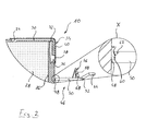
- the ink cartridge 10 is in a vertical movement in the cartridge receptacle 64th used, as indicated by the arrow to the connecting piece 14 with the To couple connection (not shown) of the printer in a known manner, the on the connecting piece 14 provided film from one at the terminal of the inkjet printer piercing pin is pierced.
- the lock lever 46 comes in the insertion movement of the ink cartridge 10 with an edge 66 on the cartridge receptacle 64 in contact, through which the Locking lever 46 is pressed in the direction of the side surface 34 of the housing 12.
- the locking lever 46 in a first phase on the film hinge 48 to the Swivel axis A pivoted so far until the support surface 62 with the side surface 34 of the Housing 12 comes into contact. The completion of this first phase is shown in FIG.
- the locking lever 46 springs back slightly and comes with the as Locking edge serving edge 66 in engagement.
- the actuating mandrel 56 is again slightly withdrawn from the vent 38, the film 40 in her pierced and expanded position remains.
- air can through the Ventilation opening 36, the compensation chamber 36, the connection opening 32, the channel 30 and the opening 24 between the ink storage chamber 26 and the environment for a pressure equalization flow back and forth.
- the locking lever 46 must only with Help the trigger lever 54 briefly bent so in the direction of the ink cartridge 10 until the ratchet 52 on the locking lever 56 detaches from the edge 66. Subsequently, the ink cartridge 10 in the opposite direction again from the Cartridge receptacle 64 are removed. If there is still ink in the ink cartridge 10 is included, the user can the vent 38 and, where appropriate, the Connecting piece 14 by sticking a supplied with the ink cartridge 10, self-adhesive film to be closed again.
- the ink cartridge 10 has the advantage that the opening of the ventilation device 42 and the locking of the ink cartridge 10 by means of the locking device 44 coupled and runs in a predetermined defined order. So the opening of the vent opening 42 takes place immediately before the ink cartridge 10th is locked with the edge 66.
- This has the advantage that a pressure equalization of Ink storage chamber 26 takes place only when the connecting piece 14 of the Ink cartridge 10 in the last movement phase of its Ankoppelvorgang to the Connection of the inkjet printer is located, leaving no ink at the port of the inkjet printer can escape from the ink cartridge 10 over.
- FIGs. 5 and 6 variations of the ink cartridge 10 are shown, which are merely differ by the way in which the vent 38 before activating the Ventilation device 42 is closed.
- FIG. 5 shows a modification of the ink cartridge 10, wherein the ventilation opening 42nd instead of with the film 40 by a in the vent 38 in the manufacture of the Housing 12 injected plastic skin 70 is closed. Again, the plastic skin 70 pierced by the action of the actuating mandrel 56 and on this The ventilation device 42 is activated.
- the ventilation opening 38 is the 38th closed by a valve arrangement in the form of a ball valve 72.
- the ball valve 72 has for this purpose a valve ball 74, which by a in the compensation chamber 36th supporting compression spring 76 against the inner circumferential edge of the ventilation opening 38th is biased and closes this fluid-tight.
- the locking lever 46 is in its locking position in the above described manner, wherein the actuating element 78 with the valve ball 74th the ball valve 72 comes into contact and pushes them into the compensation chamber 36, whereby the ventilation opening 38 is opened.
- the actuator 78 is again out of the Ventilation 38 withdrawn, the valve ball 74 by the force of Compression spring 76 is moved back into its closed position, in which they the ventilation opening 38 closes fluid-tight.
- the locking lever 46 may be formed as a separate component, that is mounted on a corresponding bearing on the outside of the housing 12 is. It is also conceivable, the locking lever 46 mechanically with a ventilation opening 38 closing valve assembly, for example in the form of a Ventilation opening 38 closing slide to mechanically couple.
Landscapes
- Ink Jet (AREA)
Abstract
Description
- Fig. 1
- in perspektivischer Darstellung eine erfindungsgemäße Tintenpatrone mit einer Belüftungseinrichtung, die durch einen Verriegelungshebel aktivierbar ist,
- Fig. 2
- einen Ausschnitt einer geschnittenen Seitenansicht der erfindungsgemäßen Tintenpatrone aus Fig. 1 unmittelbar nach deren Herstellung mit einem vergrößerten Ausschnitt X eines Details des Verriegelungshebels,
- Fig. 3
- eine teilweise geschnittene Seitenansicht der erfindungsgemäßen Tintenpatrone beim Einsetzen in eine Patronenaufnahme eines Tintenstrahldruckers,
- Fig. 4
- eine teilweise geschnittene Seitenansicht der erfindungsgemäßen Tintenpatrone nach dem Verriegeln in der Patronenaufnahme,
- Fig. 5
- einen der Ansicht nach Fig. 2 entsprechenden Ausschnitt einer geschnittenen Seitenansicht einer abgewandelten Ausführungsform der erfindungsgemäßen Tintenpatrone, und
- Fig. 6
- einen der Ansicht nach Fig. 2 entsprechenden Ausschnitt einer geschnittenen Seitenansicht einer weiteren abgewandelten Ausführungsform der erfindungsgemäßen Tintenpatrone.
- 10
- Tintenpatrone
- 12
- Gehäuse
- 14
- Anschlußstutzen
- 16
- Seitenfläche
- 18
- Aufnahme
- 20
- Oberseite
- 22
- Deckel
- 24
- Öffnung
- 26
- Tintenspeicherkammer
- 28
- Tintenspeicher
- 30
- Kanal
- 32
- Verbindungsöffnung
- 34
- Seitenfläche
- 36
- Ausgleichskammer
- 38
- Belüftungsöffnung
- 40
- Folie
- 42
- Belüftungseinrichtung
- 44
- Verriegelungseinrichtung
- 46
- Verriegelungshebel
- 48
- Filmscharnier
- 50
- Biegeabschnitt
- 52
- Rasterhebung
- 54
- Auslösehebel
- 56
- Betätigungsdorn
- 58
- Flächenelemente
- 60
- Kante
- 62
- Stützfläche
- 64
- Patronenaufnahme
- 66
- Kante
- 68
- Aussparungen
- 70
- Haut
- 72
- Kugelventil
- 74
- Ventilkugel
- 76
- Druckfeder
- 78
- Betätigungselement
- A
- Schwenkache
- α
- Neigungswinkel
Claims (16)
- Tintenpatrone zum Einsetzen in eine Patronenaufnahme eines Tintenstrahldruckers, mit
einem Gehäuse (12), in dem mindestens eine Tintenspeicherkammer (26) ausgebildet ist, einer am Gehäuse (12) vorgesehenen Belüftungseinrichtung (42), die nach ihrer Aktivierung das Gehäuseinnere zum Druckausgleich mit der Umgebung verbindet, und
einer am Gehäuse (12) vorgesehenen Verriegelungseinrichtung (44) zum Verriegeln der Tintenpatrone (10) in der Patronenaufnahme (64), die zwischen einer Verriegelungsstellung, in der sie mit der Patronenaufnahme (64) verriegelt ist, und einer Entriegelungsstellung beweglich ist,
dadurch gekennzeichnet, dass die Verriegelungseinrichtung (44) gleichzeitig als Betätigungsorgan für die Aktivierung der Belüftungseinrichtung (42) dient und bei ihrer Bewegung in ihre Verriegelungsstellung mit der Belüftungseinrichtung (42) in Wirkverbindung kommt, um diese zu aktivieren. - Tintenpatrone nach Anspruch 1, dadurch gekennzeichnet, dass die Verriegelungseinrichtung (44) ein Betätigungselement (56, 78) aufweist, das in der Verriegelungsstellung der Verriegelungseinrichtung (44) mit der Belüftungseinrichtung (42) in Wirkverbindung steht.
- Tintenpatrone nach einem der Ansprüche 1 oder 2, dadurch gekennzeichnet, dass die Belüftungseinrichtung (42) eine zu deren Aktivierung zu öffnende Belüftungsöffnung (38) aufweist, und dass ein an der Verriegelungseinrichtung (44) vorgesehenes Betätigungselement (56, 78) zumindest während der Bewegung der Verriegelungseinrichtung (44) in ihre Verriegelungsstellung in die Belüftungsöffnung (38) zumindest abschnittsweise eingeführt ist, um diese zu öffnen.
- Tintenpatrone nach Anspruch 3, dadurch gekennzeichnet, dass die Belüftungsöffnung (38) vor der erstmaligen Benutzung der Tintenpatrone (10) durch eine Folie (40, 70) verschlossen ist, und dass als Betätigungselement ein Betätigungsdorn (56) dient, welcher bei der Bewegung der Verriegelungseinrichtung (44) in deren Verriegelungsstellung zum Öffnen der Belüftungsöffnung (38) die Folie (40, 70) durchstößt.
- Tintenpatrone nach Anspruch 4, dadurch gekennzeichnet, dass die die Belüftungsöffnung (38) verschließende Folie (40, 70) auf das Gehäuse (12) aufgeklebt oder aufgesiegelt oder am Gehäuse (12) angeformt ist.
- Tintenpatrone nach Anspruch 3, dadurch gekennzeichnet, dass die Belüftungsöffnung (38) durch eine Ventilanordnung, vorzugsweise durch ein Kugelventil (72), verschlossen ist, und dass das Betätigungselement (78) bei der Bewegung der Verriegelungseinrichtung (44) in deren Verriegelungsstellung mit einem Ventilelement (74), welches zwischen einer die Belüftungsöffnung (38) verschließenden Stellung und einer die Belüftungsöffnung (38) freigebenden Stellung beweglich ist, in Eingriff kommt und dieses zum Öffnen der Belüftungsöffnung (38) in seine Freigabestellung bewegt.
- Tintenpatrone nach mindestens einem der vorhergehenden Ansprüche, dadurch gekennzeichnet, dass die Belüftungseinrichtung (42) einen mit der Belüftungsöffnung (38) in Strömungsverbindung stehenden, vorzugsweise mäanderförmig verlaufenden Kanal (30) aufweist, welcher durch eine Öffnung (28) mit dem Gehäuseinneren der Tintenpatrone (10) in Strömungsverbindung steht.
- Tintenpatrone nach Anspruch 7, dadurch gekennzeichnet, dass der Kanal (30) an einer Flachseite (20) des Gehäuses (12), vorzugsweise der Oberseite (20) des Gehäuses (12), ausgebildet ist und mit einer Ausgleichskammer (36) in Strömungsverbindung steht, welche an einer an die mit dem Kanal (30) versehene Flachseite (20) des Gehäuses (12) angrenzende weitere Flachseite (34) des Gehäuses (12) vorgesehen ist, und dass die Belüftungsöffnung (38) unmittelbar in die Ausgleichskammer (36) mündet.
- Tintenpatrone nach einem der Ansprüche 7 oder 8, dadurch gekennzeichnet, dass der Kanal (30) und/oder die Ausgleichskammer (36) nach außen hin zumindest abschnittsweise offen sind bzw. ist und durch eine auf das Gehäuse (12) aufgeklebte oder aufgesiegelte Folie (40) verschlossen sind bzw. ist.
- Tintenpatrone nach mindestens einem der vorhergehenden Ansprüche, dadurch gekennzeichnet, dass die Verriegelungseinrichtung (44) als Verriegelungshebel (46) ausgebildet ist, der schwenkbar am Gehäuse (12) der Tintenpatrone (10) gelagert ist.
- Tintenpatrone nach Anspruch 10, dadurch gekennzeichnet, dass der Verriegelungshebel (46) durch ein Filmscharnier (48) am Gehäuse (12) schwenkbar gelagert ist.
- Tintenpatrone nach Anspruch 10 oder 11, dadurch gekennzeichnet, dass der Verriegelungshebel (46) in einer ersten Phase um eine Schwenkachse (A) von einer Ruhestellung bis in eine Zwischenstellung, in der er mit einer an ihm ausgebildeten Stützfläche (62) an der Außenseite des Gehäuses (12) zur Anlage kommt, zu schwenken ist, und in einer zweiten Phase, in der sich der Verriegelungshebel (46) mit seiner Stützfläche (62) am Gehäuse (12) abstützt, ausgehend von der Zwischenstellung in Richtung der Schwenkachse (A) in seine Verriegelungsstellung elastisch zu biegen ist.
- Tintenpatrone nach Anspruch 12, dadurch gekennzeichnet, dass die Stützfläche (62) in einer parallel zur Schwenkachse (A) des Verriegelungshebels (46) verlaufenden Ebene liegt.
- Tintenpatrone nach Anspruch 12 oder 13, dadurch gekennzeichnet, dass die Stützfläche (62) in einer Ebene liegt, welche mit einem Winkel (α) in einem Bereich von etwa 30 bis 60°, vorzugsweise in einem Bereich von etwa 40 bis 50° geneigt zur Flachseite des Verriegelungshebels (46) verläuft.
- Tintenpatrone nach mindestens einem der Ansprüche 10 bis 14, dadurch gekennzeichnet, dass am Verriegelungshebel (46) eine Rasterhebung (52) ausgebildet ist, welche bei eingesetzter Tintenpatrone (10) mit einer an der Patronenaufnahme (64) vorgesehenen Rastkante (66) zum Verriegeln der Tintenpatrone (10) in Eingriff bringbar ist.
- Tintenpatrone nach mindestens einem der Ansprüche 10 bis 15, dadurch gekennzeichnet, dass am Verriegelungshebel (46) ein Auslösehebel (54) vorgesehen ist, mit welchem der in der Patronenaufnahme (64) verriegelte Verriegelungshebel (46) aus seiner Verriegelung zu lösen ist.
Applications Claiming Priority (2)
| Application Number | Priority Date | Filing Date | Title |
|---|---|---|---|
| DE102004004558 | 2004-01-29 | ||
| DE102004004558A DE102004004558B4 (de) | 2004-01-29 | 2004-01-29 | Tintenpatrone |
Publications (3)
| Publication Number | Publication Date |
|---|---|
| EP1559559A2 true EP1559559A2 (de) | 2005-08-03 |
| EP1559559A3 EP1559559A3 (de) | 2007-06-06 |
| EP1559559B1 EP1559559B1 (de) | 2011-05-25 |
Family
ID=34638801
Family Applications (1)
| Application Number | Title | Priority Date | Filing Date |
|---|---|---|---|
| EP05001789A Expired - Lifetime EP1559559B1 (de) | 2004-01-29 | 2005-01-28 | Tintenpatrone |
Country Status (3)
| Country | Link |
|---|---|
| EP (1) | EP1559559B1 (de) |
| AT (1) | ATE510694T1 (de) |
| DE (1) | DE102004004558B4 (de) |
Cited By (2)
| Publication number | Priority date | Publication date | Assignee | Title |
|---|---|---|---|---|
| EP1955851A1 (de) | 2007-02-07 | 2008-08-13 | Seiko Epson Corporation | Flüssigkeitsbehälter, Recyclingverfahren für den Flüssigkeitsbehälter, Verfahren zum Durchstechen der Deckelfolie des Flüssigkeitsbehälters, Stechschablone und Verfahren zur Herstellung des Flüssigkeitsbehälters |
| CN106560322A (zh) * | 2015-10-06 | 2017-04-12 | 精工爱普生株式会社 | 液体喷射系统、通气单元、液体供给装置 |
Citations (4)
| Publication number | Priority date | Publication date | Assignee | Title |
|---|---|---|---|---|
| EP0792749A2 (de) | 1996-03-01 | 1997-09-03 | Canon Kabushiki Kaisha | Verpackungsstruktur für einen Farbvorratstank und Farbvorratstank verpackt in einer solchen Struktur |
| EP0685340B1 (de) | 1994-05-31 | 1999-08-18 | Canon Kabushiki Kaisha | Austauschbare Tintenpatrone mit Verschlussstruktur |
| JPH11268290A (ja) | 1998-03-20 | 1999-10-05 | Seiko Epson Corp | プリンタのインクカートリッジ装置 |
| EP0803365B1 (de) | 1996-04-26 | 2001-07-18 | Pelikan Hardcopy Production AG | Tintenkassette für Drucker |
Family Cites Families (6)
| Publication number | Priority date | Publication date | Assignee | Title |
|---|---|---|---|---|
| US4785314A (en) * | 1984-03-14 | 1988-11-15 | Canon Kabushiki Kaisha | Internally pressure-regulated ink supply |
| JPS60192639A (ja) * | 1984-03-14 | 1985-10-01 | Canon Inc | 液体噴射記録ユニツト |
| JP2000094710A (ja) * | 1998-09-24 | 2000-04-04 | Seiko Epson Corp | 印刷ヘッド装置、インクジェットプリンタおよびインクカートリッジ |
| US6761441B2 (en) * | 2001-12-14 | 2004-07-13 | Monitek Electronics Limited | Ink cartridge |
| US20030184625A1 (en) * | 2002-04-02 | 2003-10-02 | Pui Kuong Lui | Ink cartridge |
| CN100333914C (zh) * | 2002-06-11 | 2007-08-29 | 精工爱普生株式会社 | 墨盒 |
-
2004
- 2004-01-29 DE DE102004004558A patent/DE102004004558B4/de not_active Expired - Fee Related
-
2005
- 2005-01-28 EP EP05001789A patent/EP1559559B1/de not_active Expired - Lifetime
- 2005-01-28 AT AT05001789T patent/ATE510694T1/de active
Patent Citations (4)
| Publication number | Priority date | Publication date | Assignee | Title |
|---|---|---|---|---|
| EP0685340B1 (de) | 1994-05-31 | 1999-08-18 | Canon Kabushiki Kaisha | Austauschbare Tintenpatrone mit Verschlussstruktur |
| EP0792749A2 (de) | 1996-03-01 | 1997-09-03 | Canon Kabushiki Kaisha | Verpackungsstruktur für einen Farbvorratstank und Farbvorratstank verpackt in einer solchen Struktur |
| EP0803365B1 (de) | 1996-04-26 | 2001-07-18 | Pelikan Hardcopy Production AG | Tintenkassette für Drucker |
| JPH11268290A (ja) | 1998-03-20 | 1999-10-05 | Seiko Epson Corp | プリンタのインクカートリッジ装置 |
Cited By (8)
| Publication number | Priority date | Publication date | Assignee | Title |
|---|---|---|---|---|
| EP1955851A1 (de) | 2007-02-07 | 2008-08-13 | Seiko Epson Corporation | Flüssigkeitsbehälter, Recyclingverfahren für den Flüssigkeitsbehälter, Verfahren zum Durchstechen der Deckelfolie des Flüssigkeitsbehälters, Stechschablone und Verfahren zur Herstellung des Flüssigkeitsbehälters |
| US8162456B2 (en) | 2007-02-07 | 2012-04-24 | Seiko Epson Corporation | Fluid container, recycling method of fluid container, method for piercing cover film of fluid container, piercing jig, and method for manufacturing fluid container |
| CN106560322A (zh) * | 2015-10-06 | 2017-04-12 | 精工爱普生株式会社 | 液体喷射系统、通气单元、液体供给装置 |
| EP3156237A1 (de) * | 2015-10-06 | 2017-04-19 | Seiko Epson Corporation | Flüssigkeitsausstosssystem, belüftungseinheit, flüssigkeitsversorgungsvorrichtung |
| US9908352B2 (en) | 2015-10-06 | 2018-03-06 | Seiko Epson Corporation | Liquid ejection system, ventilation unit, liquid supply apparatus |
| CN106560322B (zh) * | 2015-10-06 | 2020-01-07 | 精工爱普生株式会社 | 液体喷射系统、通气单元、液体供给装置 |
| CN110962460A (zh) * | 2015-10-06 | 2020-04-07 | 精工爱普生株式会社 | 液体喷射系统、通气单元、液体供给装置 |
| CN110962460B (zh) * | 2015-10-06 | 2021-01-05 | 精工爱普生株式会社 | 液体喷射系统、通气单元、液体供给装置 |
Also Published As
| Publication number | Publication date |
|---|---|
| EP1559559A3 (de) | 2007-06-06 |
| DE102004004558B4 (de) | 2008-01-03 |
| ATE510694T1 (de) | 2011-06-15 |
| DE102004004558A1 (de) | 2005-10-13 |
| EP1559559B1 (de) | 2011-05-25 |
Similar Documents
| Publication | Publication Date | Title |
|---|---|---|
| DE69635529T2 (de) | Tintenbehälter, Herstellungsverfahren für Tintenbehälter | |
| DE60313038T2 (de) | Flaschenverschluss mit kontrollierter öffnungsbewegung | |
| DE60008169T2 (de) | Anordnung für einen deckellosen Einfüllstutzen eines Kraftstofftanks | |
| DE102009047004B4 (de) | Vorrichtung zum Öffnen und Schließen eines Kraftstofftanks | |
| EP2398664B1 (de) | Sicherheitselement für einen diesel-kraftstoffbehälter zur unterbindung einer fehlbetankung | |
| EP2300256B1 (de) | Einsatzelement für einen zur tankstellenseitigen befüllung mit harnstoff geeigneten behälter | |
| DE69317543T2 (de) | Tintennachfüllbehälter und Tintennachfüllverfahren unter Verwendung desselben | |
| EP0094499A1 (de) | Verdunstungsvorrichtung für Insektizide, Duftstoffe und/oder andere flüchtige Wirkstoffe | |
| WO2012110335A1 (de) | Wiederverschliessbare trinkdose | |
| DE4237790C2 (de) | Selbstschließender Behälterverschluß | |
| EP1420660A1 (de) | Behälter für zigaretten- oder zigarilloverpackungen | |
| DE102014000425A1 (de) | Abgabevorrichtung | |
| DE3716288A1 (de) | Schliessvorrichtung fuer eine einen hohlraum abschliessende klappe oder dergleichen | |
| WO2013170282A2 (de) | Stempel, insbesondere rund-stempel | |
| EP1559559B1 (de) | Tintenpatrone | |
| DE102006031463A1 (de) | Einfüllstutzen für das Einfüllen von Dieselkraftstoff in einen Fahrzeugtank | |
| DE3232340C1 (de) | Selbstschliessender Kraftstoffbehaelterverschluss | |
| DE69524799T2 (de) | Überrollventil für die Entlüftung und die Sicherheit eines KFZ-Kraftstoffbehälters | |
| EP1481734B1 (de) | Verschluss für einen Sprühkopf | |
| EP1556224B1 (de) | Tintenpatrone zum aufbringen auf einen aufzeichnungskopf | |
| WO2017108156A1 (de) | Beduftungsvorrichtung für ein fahrzeug | |
| DE19839225A1 (de) | Tintenstrahldrucker und Wechselbehälter für Drucktinte | |
| DE102017127313A1 (de) | Kunststoffverschluss für Behälter | |
| DE102009029453A1 (de) | Vorrichtung zur Aufnahme und Abgabe von Getränken | |
| DE102008031250A1 (de) | Sicherheitselement für einen Diesel-Kraftstoffbehälter zur Unterbindung einer Fehlbetankung |
Legal Events
| Date | Code | Title | Description |
|---|---|---|---|
| PUAI | Public reference made under article 153(3) epc to a published international application that has entered the european phase |
Free format text: ORIGINAL CODE: 0009012 |
|
| AK | Designated contracting states |
Kind code of ref document: A2 Designated state(s): AT BE BG CH CY CZ DE DK EE ES FI FR GB GR HU IE IS IT LI LT LU MC NL PL PT RO SE SI SK TR |
|
| AX | Request for extension of the european patent |
Extension state: AL BA HR LV MK YU |
|
| PUAL | Search report despatched |
Free format text: ORIGINAL CODE: 0009013 |
|
| AK | Designated contracting states |
Kind code of ref document: A3 Designated state(s): AT BE BG CH CY CZ DE DK EE ES FI FR GB GR HU IE IS IT LI LT LU MC NL PL PT RO SE SI SK TR |
|
| AX | Request for extension of the european patent |
Extension state: AL BA HR LV MK YU |
|
| 17P | Request for examination filed |
Effective date: 20070615 |
|
| AKX | Designation fees paid |
Designated state(s): AT BE BG CH CY CZ DE DK EE ES FI FR GB GR HU IE IS IT LI LT LU MC NL PL PT RO SE SI SK TR |
|
| 17Q | First examination report despatched |
Effective date: 20100215 |
|
| GRAP | Despatch of communication of intention to grant a patent |
Free format text: ORIGINAL CODE: EPIDOSNIGR1 |
|
| GRAS | Grant fee paid |
Free format text: ORIGINAL CODE: EPIDOSNIGR3 |
|
| GRAA | (expected) grant |
Free format text: ORIGINAL CODE: 0009210 |
|
| AK | Designated contracting states |
Kind code of ref document: B1 Designated state(s): AT BE BG CH CY CZ DE DK EE ES FI FR GB GR HU IE IS IT LI LT LU MC NL PL PT RO SE SI SK TR |
|
| REG | Reference to a national code |
Ref country code: GB Ref legal event code: FG4D Free format text: NOT ENGLISH |
|
| REG | Reference to a national code |
Ref country code: CH Ref legal event code: EP |
|
| REG | Reference to a national code |
Ref country code: IE Ref legal event code: FG4D Free format text: LANGUAGE OF EP DOCUMENT: GERMAN |
|
| REG | Reference to a national code |
Ref country code: DE Ref legal event code: R096 Ref document number: 502005011415 Country of ref document: DE Effective date: 20110707 |
|
| REG | Reference to a national code |
Ref country code: CH Ref legal event code: PFA Owner name: PELIKAN HARDCOPY PRODUCTION AG Free format text: PELIKAN HARDCOPY PRODUCTION AG#LEESTRASSE 1#8132 EGG (CH) -TRANSFER TO- PELIKAN HARDCOPY PRODUCTION AG#HALDENSTRASSE 30#8620 WETZIKON (CH) |
|
| REG | Reference to a national code |
Ref country code: NL Ref legal event code: VDEP Effective date: 20110525 |
|
| RAP2 | Party data changed (patent owner data changed or rights of a patent transferred) |
Owner name: PELIKAN HARDCOPY PRODUCTION AG |
|
| PG25 | Lapsed in a contracting state [announced via postgrant information from national office to epo] |
Ref country code: PT Free format text: LAPSE BECAUSE OF FAILURE TO SUBMIT A TRANSLATION OF THE DESCRIPTION OR TO PAY THE FEE WITHIN THE PRESCRIBED TIME-LIMIT Effective date: 20110926 Ref country code: SE Free format text: LAPSE BECAUSE OF FAILURE TO SUBMIT A TRANSLATION OF THE DESCRIPTION OR TO PAY THE FEE WITHIN THE PRESCRIBED TIME-LIMIT Effective date: 20110525 Ref country code: LT Free format text: LAPSE BECAUSE OF FAILURE TO SUBMIT A TRANSLATION OF THE DESCRIPTION OR TO PAY THE FEE WITHIN THE PRESCRIBED TIME-LIMIT Effective date: 20110525 |
|
| PG25 | Lapsed in a contracting state [announced via postgrant information from national office to epo] |
Ref country code: ES Free format text: LAPSE BECAUSE OF FAILURE TO SUBMIT A TRANSLATION OF THE DESCRIPTION OR TO PAY THE FEE WITHIN THE PRESCRIBED TIME-LIMIT Effective date: 20110905 Ref country code: IS Free format text: LAPSE BECAUSE OF FAILURE TO SUBMIT A TRANSLATION OF THE DESCRIPTION OR TO PAY THE FEE WITHIN THE PRESCRIBED TIME-LIMIT Effective date: 20110925 Ref country code: SI Free format text: LAPSE BECAUSE OF FAILURE TO SUBMIT A TRANSLATION OF THE DESCRIPTION OR TO PAY THE FEE WITHIN THE PRESCRIBED TIME-LIMIT Effective date: 20110525 Ref country code: CY Free format text: LAPSE BECAUSE OF FAILURE TO SUBMIT A TRANSLATION OF THE DESCRIPTION OR TO PAY THE FEE WITHIN THE PRESCRIBED TIME-LIMIT Effective date: 20110525 Ref country code: FI Free format text: LAPSE BECAUSE OF FAILURE TO SUBMIT A TRANSLATION OF THE DESCRIPTION OR TO PAY THE FEE WITHIN THE PRESCRIBED TIME-LIMIT Effective date: 20110525 Ref country code: GR Free format text: LAPSE BECAUSE OF FAILURE TO SUBMIT A TRANSLATION OF THE DESCRIPTION OR TO PAY THE FEE WITHIN THE PRESCRIBED TIME-LIMIT Effective date: 20110826 |
|
| REG | Reference to a national code |
Ref country code: IE Ref legal event code: FD4D |
|
| PG25 | Lapsed in a contracting state [announced via postgrant information from national office to epo] |
Ref country code: NL Free format text: LAPSE BECAUSE OF FAILURE TO SUBMIT A TRANSLATION OF THE DESCRIPTION OR TO PAY THE FEE WITHIN THE PRESCRIBED TIME-LIMIT Effective date: 20110525 |
|
| REG | Reference to a national code |
Ref country code: DE Ref legal event code: R082 Ref document number: 502005011415 Country of ref document: DE Representative=s name: MEISSNER, BOLTE & PARTNER GBR, DE |
|
| PG25 | Lapsed in a contracting state [announced via postgrant information from national office to epo] |
Ref country code: EE Free format text: LAPSE BECAUSE OF FAILURE TO SUBMIT A TRANSLATION OF THE DESCRIPTION OR TO PAY THE FEE WITHIN THE PRESCRIBED TIME-LIMIT Effective date: 20110525 Ref country code: IE Free format text: LAPSE BECAUSE OF FAILURE TO SUBMIT A TRANSLATION OF THE DESCRIPTION OR TO PAY THE FEE WITHIN THE PRESCRIBED TIME-LIMIT Effective date: 20110525 Ref country code: CZ Free format text: LAPSE BECAUSE OF FAILURE TO SUBMIT A TRANSLATION OF THE DESCRIPTION OR TO PAY THE FEE WITHIN THE PRESCRIBED TIME-LIMIT Effective date: 20110525 |
|
| PG25 | Lapsed in a contracting state [announced via postgrant information from national office to epo] |
Ref country code: DK Free format text: LAPSE BECAUSE OF FAILURE TO SUBMIT A TRANSLATION OF THE DESCRIPTION OR TO PAY THE FEE WITHIN THE PRESCRIBED TIME-LIMIT Effective date: 20110525 Ref country code: SK Free format text: LAPSE BECAUSE OF FAILURE TO SUBMIT A TRANSLATION OF THE DESCRIPTION OR TO PAY THE FEE WITHIN THE PRESCRIBED TIME-LIMIT Effective date: 20110525 Ref country code: PL Free format text: LAPSE BECAUSE OF FAILURE TO SUBMIT A TRANSLATION OF THE DESCRIPTION OR TO PAY THE FEE WITHIN THE PRESCRIBED TIME-LIMIT Effective date: 20110525 Ref country code: RO Free format text: LAPSE BECAUSE OF FAILURE TO SUBMIT A TRANSLATION OF THE DESCRIPTION OR TO PAY THE FEE WITHIN THE PRESCRIBED TIME-LIMIT Effective date: 20110525 |
|
| REG | Reference to a national code |
Ref country code: DE Ref legal event code: R081 Ref document number: 502005011415 Country of ref document: DE Owner name: PELIKAN HARDCOPY PRODUCTION AG, CH Free format text: FORMER OWNER: PELIKAN HARDCOPY PRODUCTION AG, EGG, CH Effective date: 20120116 Ref country code: DE Ref legal event code: R082 Ref document number: 502005011415 Country of ref document: DE Representative=s name: MEISSNER, BOLTE & PARTNER GBR, DE Effective date: 20120116 Ref country code: DE Ref legal event code: R082 Ref document number: 502005011415 Country of ref document: DE Representative=s name: MEISSNER BOLTE PATENTANWAELTE RECHTSANWAELTE P, DE Effective date: 20120116 |
|
| PLBE | No opposition filed within time limit |
Free format text: ORIGINAL CODE: 0009261 |
|
| STAA | Information on the status of an ep patent application or granted ep patent |
Free format text: STATUS: NO OPPOSITION FILED WITHIN TIME LIMIT |
|
| PGFP | Annual fee paid to national office [announced via postgrant information from national office to epo] |
Ref country code: FR Payment date: 20120201 Year of fee payment: 8 Ref country code: CH Payment date: 20120124 Year of fee payment: 8 |
|
| 26N | No opposition filed |
Effective date: 20120228 |
|
| PG25 | Lapsed in a contracting state [announced via postgrant information from national office to epo] |
Ref country code: IT Free format text: LAPSE BECAUSE OF FAILURE TO SUBMIT A TRANSLATION OF THE DESCRIPTION OR TO PAY THE FEE WITHIN THE PRESCRIBED TIME-LIMIT Effective date: 20110525 |
|
| REG | Reference to a national code |
Ref country code: DE Ref legal event code: R097 Ref document number: 502005011415 Country of ref document: DE Effective date: 20120228 |
|
| PGFP | Annual fee paid to national office [announced via postgrant information from national office to epo] |
Ref country code: GB Payment date: 20120124 Year of fee payment: 8 |
|
| BERE | Be: lapsed |
Owner name: PELIKAN HARDCOPY PRODUCTION A.G. Effective date: 20120131 |
|
| PG25 | Lapsed in a contracting state [announced via postgrant information from national office to epo] |
Ref country code: MC Free format text: LAPSE BECAUSE OF NON-PAYMENT OF DUE FEES Effective date: 20120131 |
|
| PG25 | Lapsed in a contracting state [announced via postgrant information from national office to epo] |
Ref country code: BE Free format text: LAPSE BECAUSE OF NON-PAYMENT OF DUE FEES Effective date: 20120131 |
|
| REG | Reference to a national code |
Ref country code: AT Ref legal event code: MM01 Ref document number: 510694 Country of ref document: AT Kind code of ref document: T Effective date: 20120128 |
|
| PG25 | Lapsed in a contracting state [announced via postgrant information from national office to epo] |
Ref country code: AT Free format text: LAPSE BECAUSE OF NON-PAYMENT OF DUE FEES Effective date: 20120128 Ref country code: BG Free format text: LAPSE BECAUSE OF FAILURE TO SUBMIT A TRANSLATION OF THE DESCRIPTION OR TO PAY THE FEE WITHIN THE PRESCRIBED TIME-LIMIT Effective date: 20110825 |
|
| REG | Reference to a national code |
Ref country code: CH Ref legal event code: PL |
|
| GBPC | Gb: european patent ceased through non-payment of renewal fee |
Effective date: 20130128 |
|
| REG | Reference to a national code |
Ref country code: FR Ref legal event code: ST Effective date: 20130930 |
|
| PG25 | Lapsed in a contracting state [announced via postgrant information from national office to epo] |
Ref country code: LI Free format text: LAPSE BECAUSE OF NON-PAYMENT OF DUE FEES Effective date: 20130131 Ref country code: CH Free format text: LAPSE BECAUSE OF NON-PAYMENT OF DUE FEES Effective date: 20130131 |
|
| PG25 | Lapsed in a contracting state [announced via postgrant information from national office to epo] |
Ref country code: FR Free format text: LAPSE BECAUSE OF NON-PAYMENT OF DUE FEES Effective date: 20130131 Ref country code: GB Free format text: LAPSE BECAUSE OF NON-PAYMENT OF DUE FEES Effective date: 20130128 |
|
| PG25 | Lapsed in a contracting state [announced via postgrant information from national office to epo] |
Ref country code: TR Free format text: LAPSE BECAUSE OF FAILURE TO SUBMIT A TRANSLATION OF THE DESCRIPTION OR TO PAY THE FEE WITHIN THE PRESCRIBED TIME-LIMIT Effective date: 20110525 |
|
| PG25 | Lapsed in a contracting state [announced via postgrant information from national office to epo] |
Ref country code: LU Free format text: LAPSE BECAUSE OF NON-PAYMENT OF DUE FEES Effective date: 20120128 |
|
| PG25 | Lapsed in a contracting state [announced via postgrant information from national office to epo] |
Ref country code: HU Free format text: LAPSE BECAUSE OF FAILURE TO SUBMIT A TRANSLATION OF THE DESCRIPTION OR TO PAY THE FEE WITHIN THE PRESCRIBED TIME-LIMIT Effective date: 20050128 |
|
| PGFP | Annual fee paid to national office [announced via postgrant information from national office to epo] |
Ref country code: DE Payment date: 20150120 Year of fee payment: 11 |
|
| REG | Reference to a national code |
Ref country code: DE Ref legal event code: R119 Ref document number: 502005011415 Country of ref document: DE |
|
| PG25 | Lapsed in a contracting state [announced via postgrant information from national office to epo] |
Ref country code: DE Free format text: LAPSE BECAUSE OF NON-PAYMENT OF DUE FEES Effective date: 20160802 |