EP0631460B1 - Gedruckte Schaltung - Google Patents
Gedruckte Schaltung Download PDFInfo
- Publication number
- EP0631460B1 EP0631460B1 EP94202846A EP94202846A EP0631460B1 EP 0631460 B1 EP0631460 B1 EP 0631460B1 EP 94202846 A EP94202846 A EP 94202846A EP 94202846 A EP94202846 A EP 94202846A EP 0631460 B1 EP0631460 B1 EP 0631460B1
- Authority
- EP
- European Patent Office
- Prior art keywords
- pattern
- printed circuit
- conductive layer
- layer
- circuit board
- Prior art date
- Legal status (The legal status is an assumption and is not a legal conclusion. Google has not performed a legal analysis and makes no representation as to the accuracy of the status listed.)
- Expired - Lifetime
Links
- 239000003990 capacitor Substances 0.000 claims description 65
- 239000000758 substrate Substances 0.000 claims description 29
- 238000009413 insulation Methods 0.000 claims description 21
- 238000007639 printing Methods 0.000 claims description 10
- 238000000034 method Methods 0.000 claims description 8
- 238000007650 screen-printing Methods 0.000 claims description 7
- 238000004519 manufacturing process Methods 0.000 claims description 4
- 230000000694 effects Effects 0.000 description 22
- 230000005855 radiation Effects 0.000 description 20
- 239000000463 material Substances 0.000 description 10
- 230000001629 suppression Effects 0.000 description 10
- RYGMFSIKBFXOCR-UHFFFAOYSA-N Copper Chemical compound [Cu] RYGMFSIKBFXOCR-UHFFFAOYSA-N 0.000 description 9
- WABPQHHGFIMREM-UHFFFAOYSA-N lead(0) Chemical compound [Pb] WABPQHHGFIMREM-UHFFFAOYSA-N 0.000 description 8
- 239000011347 resin Substances 0.000 description 7
- 229920005989 resin Polymers 0.000 description 7
- 229910052802 copper Inorganic materials 0.000 description 6
- 239000010949 copper Substances 0.000 description 6
- 239000000203 mixture Substances 0.000 description 6
- 239000012774 insulation material Substances 0.000 description 4
- 238000000206 photolithography Methods 0.000 description 4
- 238000005476 soldering Methods 0.000 description 4
- 230000015572 biosynthetic process Effects 0.000 description 3
- 239000002245 particle Substances 0.000 description 3
- 239000005011 phenolic resin Substances 0.000 description 3
- 230000005540 biological transmission Effects 0.000 description 2
- 238000007796 conventional method Methods 0.000 description 2
- 239000003822 epoxy resin Substances 0.000 description 2
- 239000003365 glass fiber Substances 0.000 description 2
- 239000002241 glass-ceramic Substances 0.000 description 2
- 239000002184 metal Substances 0.000 description 2
- 229910052751 metal Inorganic materials 0.000 description 2
- 229920000647 polyepoxide Polymers 0.000 description 2
- 229910000679 solder Inorganic materials 0.000 description 2
- 239000004640 Melamine resin Substances 0.000 description 1
- 229920000877 Melamine resin Polymers 0.000 description 1
- 239000000654 additive Substances 0.000 description 1
- 239000011230 binding agent Substances 0.000 description 1
- 230000033228 biological regulation Effects 0.000 description 1
- 239000013522 chelant Substances 0.000 description 1
- 239000003795 chemical substances by application Substances 0.000 description 1
- 238000010276 construction Methods 0.000 description 1
- 239000011889 copper foil Substances 0.000 description 1
- 230000007423 decrease Effects 0.000 description 1
- 235000014113 dietary fatty acids Nutrition 0.000 description 1
- 230000005684 electric field Effects 0.000 description 1
- 238000002474 experimental method Methods 0.000 description 1
- 229930195729 fatty acid Natural products 0.000 description 1
- 239000000194 fatty acid Substances 0.000 description 1
- 150000004665 fatty acids Chemical class 0.000 description 1
- 239000000945 filler Substances 0.000 description 1
- 230000010354 integration Effects 0.000 description 1
- 230000035699 permeability Effects 0.000 description 1
- 230000002085 persistent effect Effects 0.000 description 1
- 229920001225 polyester resin Polymers 0.000 description 1
- 239000004645 polyester resin Substances 0.000 description 1
- 230000002265 prevention Effects 0.000 description 1
- 229920003987 resole Polymers 0.000 description 1
- 150000003839 salts Chemical class 0.000 description 1
Images


Classifications
-
- H—ELECTRICITY
- H05—ELECTRIC TECHNIQUES NOT OTHERWISE PROVIDED FOR
- H05K—PRINTED CIRCUITS; CASINGS OR CONSTRUCTIONAL DETAILS OF ELECTRIC APPARATUS; MANUFACTURE OF ASSEMBLAGES OF ELECTRICAL COMPONENTS
- H05K1/00—Printed circuits
- H05K1/02—Details
- H05K1/0213—Electrical arrangements not otherwise provided for
- H05K1/0216—Reduction of cross-talk, noise or electromagnetic interference
- H05K1/0218—Reduction of cross-talk, noise or electromagnetic interference by printed shielding conductors, ground planes or power plane
-
- H—ELECTRICITY
- H05—ELECTRIC TECHNIQUES NOT OTHERWISE PROVIDED FOR
- H05K—PRINTED CIRCUITS; CASINGS OR CONSTRUCTIONAL DETAILS OF ELECTRIC APPARATUS; MANUFACTURE OF ASSEMBLAGES OF ELECTRICAL COMPONENTS
- H05K1/00—Printed circuits
- H05K1/16—Printed circuits incorporating printed electric components, e.g. printed resistor, capacitor, inductor
- H05K1/162—Printed circuits incorporating printed electric components, e.g. printed resistor, capacitor, inductor incorporating printed capacitors
-
- H—ELECTRICITY
- H05—ELECTRIC TECHNIQUES NOT OTHERWISE PROVIDED FOR
- H05K—PRINTED CIRCUITS; CASINGS OR CONSTRUCTIONAL DETAILS OF ELECTRIC APPARATUS; MANUFACTURE OF ASSEMBLAGES OF ELECTRICAL COMPONENTS
- H05K9/00—Screening of apparatus or components against electric or magnetic fields
- H05K9/0007—Casings
- H05K9/002—Casings with localised screening
- H05K9/0039—Galvanic coupling of ground layer on printed circuit board [PCB] to conductive casing
-
- H—ELECTRICITY
- H05—ELECTRIC TECHNIQUES NOT OTHERWISE PROVIDED FOR
- H05K—PRINTED CIRCUITS; CASINGS OR CONSTRUCTIONAL DETAILS OF ELECTRIC APPARATUS; MANUFACTURE OF ASSEMBLAGES OF ELECTRICAL COMPONENTS
- H05K1/00—Printed circuits
- H05K1/02—Details
- H05K1/09—Use of materials for the conductive, e.g. metallic pattern
- H05K1/092—Dispersed materials, e.g. conductive pastes or inks
- H05K1/095—Dispersed materials, e.g. conductive pastes or inks for polymer thick films, i.e. having a permanent organic polymeric binder
-
- H—ELECTRICITY
- H05—ELECTRIC TECHNIQUES NOT OTHERWISE PROVIDED FOR
- H05K—PRINTED CIRCUITS; CASINGS OR CONSTRUCTIONAL DETAILS OF ELECTRIC APPARATUS; MANUFACTURE OF ASSEMBLAGES OF ELECTRICAL COMPONENTS
- H05K1/00—Printed circuits
- H05K1/02—Details
- H05K1/11—Printed elements for providing electric connections to or between printed circuits
- H05K1/117—Pads along the edge of rigid circuit boards, e.g. for pluggable connectors
-
- H—ELECTRICITY
- H05—ELECTRIC TECHNIQUES NOT OTHERWISE PROVIDED FOR
- H05K—PRINTED CIRCUITS; CASINGS OR CONSTRUCTIONAL DETAILS OF ELECTRIC APPARATUS; MANUFACTURE OF ASSEMBLAGES OF ELECTRICAL COMPONENTS
- H05K2201/00—Indexing scheme relating to printed circuits covered by H05K1/00
- H05K2201/07—Electric details
- H05K2201/0707—Shielding
- H05K2201/0715—Shielding provided by an outer layer of PCB
-
- H—ELECTRICITY
- H05—ELECTRIC TECHNIQUES NOT OTHERWISE PROVIDED FOR
- H05K—PRINTED CIRCUITS; CASINGS OR CONSTRUCTIONAL DETAILS OF ELECTRIC APPARATUS; MANUFACTURE OF ASSEMBLAGES OF ELECTRICAL COMPONENTS
- H05K2201/00—Indexing scheme relating to printed circuits covered by H05K1/00
- H05K2201/09—Shape and layout
- H05K2201/09209—Shape and layout details of conductors
- H05K2201/09218—Conductive traces
- H05K2201/09236—Parallel layout
-
- H—ELECTRICITY
- H05—ELECTRIC TECHNIQUES NOT OTHERWISE PROVIDED FOR
- H05K—PRINTED CIRCUITS; CASINGS OR CONSTRUCTIONAL DETAILS OF ELECTRIC APPARATUS; MANUFACTURE OF ASSEMBLAGES OF ELECTRICAL COMPONENTS
- H05K2201/00—Indexing scheme relating to printed circuits covered by H05K1/00
- H05K2201/09—Shape and layout
- H05K2201/09209—Shape and layout details of conductors
- H05K2201/09218—Conductive traces
- H05K2201/09272—Layout details of angles or corners
-
- H—ELECTRICITY
- H05—ELECTRIC TECHNIQUES NOT OTHERWISE PROVIDED FOR
- H05K—PRINTED CIRCUITS; CASINGS OR CONSTRUCTIONAL DETAILS OF ELECTRIC APPARATUS; MANUFACTURE OF ASSEMBLAGES OF ELECTRICAL COMPONENTS
- H05K2201/00—Indexing scheme relating to printed circuits covered by H05K1/00
- H05K2201/09—Shape and layout
- H05K2201/09209—Shape and layout details of conductors
- H05K2201/09654—Shape and layout details of conductors covering at least two types of conductors provided for in H05K2201/09218 - H05K2201/095
- H05K2201/09672—Superposed layout, i.e. in different planes
-
- H—ELECTRICITY
- H05—ELECTRIC TECHNIQUES NOT OTHERWISE PROVIDED FOR
- H05K—PRINTED CIRCUITS; CASINGS OR CONSTRUCTIONAL DETAILS OF ELECTRIC APPARATUS; MANUFACTURE OF ASSEMBLAGES OF ELECTRICAL COMPONENTS
- H05K2201/00—Indexing scheme relating to printed circuits covered by H05K1/00
- H05K2201/10—Details of components or other objects attached to or integrated in a printed circuit board
- H05K2201/10613—Details of electrical connections of non-printed components, e.g. special leads
- H05K2201/10621—Components characterised by their electrical contacts
- H05K2201/10689—Leaded Integrated Circuit [IC] package, e.g. dual-in-line [DIL]
-
- H—ELECTRICITY
- H05—ELECTRIC TECHNIQUES NOT OTHERWISE PROVIDED FOR
- H05K—PRINTED CIRCUITS; CASINGS OR CONSTRUCTIONAL DETAILS OF ELECTRIC APPARATUS; MANUFACTURE OF ASSEMBLAGES OF ELECTRICAL COMPONENTS
- H05K3/00—Apparatus or processes for manufacturing printed circuits
- H05K3/30—Assembling printed circuits with electric components, e.g. with resistor
- H05K3/32—Assembling printed circuits with electric components, e.g. with resistor electrically connecting electric components or wires to printed circuits
- H05K3/34—Assembling printed circuits with electric components, e.g. with resistor electrically connecting electric components or wires to printed circuits by soldering
- H05K3/3447—Lead-in-hole components
-
- H—ELECTRICITY
- H05—ELECTRIC TECHNIQUES NOT OTHERWISE PROVIDED FOR
- H05K—PRINTED CIRCUITS; CASINGS OR CONSTRUCTIONAL DETAILS OF ELECTRIC APPARATUS; MANUFACTURE OF ASSEMBLAGES OF ELECTRICAL COMPONENTS
- H05K3/00—Apparatus or processes for manufacturing printed circuits
- H05K3/46—Manufacturing multilayer circuits
- H05K3/4644—Manufacturing multilayer circuits by building the multilayer layer by layer, i.e. build-up multilayer circuits
- H05K3/4664—Adding a circuit layer by thick film methods, e.g. printing techniques or by other techniques for making conductive patterns by using pastes, inks or powders
-
- Y—GENERAL TAGGING OF NEW TECHNOLOGICAL DEVELOPMENTS; GENERAL TAGGING OF CROSS-SECTIONAL TECHNOLOGIES SPANNING OVER SEVERAL SECTIONS OF THE IPC; TECHNICAL SUBJECTS COVERED BY FORMER USPC CROSS-REFERENCE ART COLLECTIONS [XRACs] AND DIGESTS
- Y10—TECHNICAL SUBJECTS COVERED BY FORMER USPC
- Y10S—TECHNICAL SUBJECTS COVERED BY FORMER USPC CROSS-REFERENCE ART COLLECTIONS [XRACs] AND DIGESTS
- Y10S428/00—Stock material or miscellaneous articles
- Y10S428/901—Printed circuit
Definitions
- This invention relates to a printed circuit board e.g. for use in electronic equipment, such as a printed circuit board for which electromagnetic interference (EMI) preventing means is taken.
- EMI electromagnetic interference
- One of the typical EMI preventing means which are conventionally applied is to reduce the radiation noise and incoming noise by covering printed circuit board with the shield case.
- This printed circuit board features that an insulation layer (hereinafter this insulation layer is called the undercoat layer) is formed, excepting at least a part of ground pattern, on a substrate on which a signal line pattern (hereinafter referred to as signal pattern), a ground line pattern (herein after referred to as ground pattern) and a power line pattern (hereinafter referred to as power supply pattern) are formed, and a conductive layer such as conductive paste layer is formed thereon so as to be connected to an uninsulated part of the ground pattern.
- a signal line pattern hereinafter referred to as signal pattern
- ground pattern ground line pattern
- power supply pattern hereinafter referred to as power supply pattern
- overcoat layer another insulation layer (hereinafter referred to as overcoat layer) is formed on this conductive layer.
- Radiation noise can be reduced in the printed circuit boards of such a configuration mainly for the following four reasons.
- Another reason is a shield effect by conductive layer itself.
- the width of the ground pattern led to the IC ground pattern is small, so that the impedance at high frequency is high, resulting in occurrence of potential difference along its length and, thereby, in unstable ground level of IC.
- the radiation noise is caused, and by the same reason the radiation noise is caused in the output signal of IC. Due to this, sufficient effect of EMI preventing means cannot be obtained.
- bypass capacitor to bypass high frequency noise is provided on the connector located at the end of substrate, power supply terminal and ground terminal.
- the required function of this bypass capacitor is to bypass the unnecessary high frequency component. Therefore bypass capacitor of relatively small capacitance is used.
- this bypass capacitor is mounted on substrate as a discrete part. Therefore soldering is required to mount the capacitor on the substrate, which impedes reduction of size of substrate.
- the lead wire of bypass capacitor causes inductance at high frequency, as a result of which the frequency characteristics of impedance are degraded.
- bypass capacitors are provided between ground pattern and circuit pattern or between power supply pattern and ground pattern so as to bypass the unnecessary high frequency component.
- this bypass capacitor is mounted on the substrate by soldering as a discrete part. Therefore, soldering is required, and existence of bypass capacitor impedes the reduction of size of substrate.
- the lead wire of bypass capacitor causes inductance at high frequency, as a result of which the frequency characteristics of impedance are degraded.
- the conductive layer is formed only around IC excepting the part just below IC. Therefore the effect of conductive layer could not be sufficiently utilized.
- the layout of printed circuit board is varied depending on uses. Hence, in some cases the sufficient ground pattern area to connect a conductive layer cannot be provided. In these case the area to connect the ground pattern and the conductive layer is small, and high frequency impedance is increased, resulting in reduction of effect. To prevent potential difference in the ground circuit, it is desirable to connect the ground pattern and the conductive layer in several places. If such a connection is impossible owing to restriction of layout, the requirement to EMI could not be satisfied sufficiently.
- An embodiment of the invention provides a printed circuit board on which a bypass capacitor is formed by using a conductive layer.
- An embodiment of the invention provides a printed circuit board on which a bypass capacitor is formed at a place by forming shield conductive layers on both sides of an insulation layer.
- An embodiment of the invention provides a printed circuit board on which an electromagnetic wave radiation noise reduction effect given by a conductive layer is not degraded even when the signal pattern pitch is made finer.
- An embodiment of the invention provides a printed circuit board capable of providing a suppression effect for EMI prevention means on a layout affording easy connection to the power supply pattern even when the conductive layer and ground pattern connection area is restricted.
- a conductive layer is provided above the connector land, so that a capacitor is composed of this conductive layer and the connector land through the insulation layer.
- This capacitor serves as a bypass capacitor.
- a bypass capacitor is composed of this power terminal land and the conductive layer located thereabove.
- the conductive layer is connected to the power supply pattern, and at the connector the bypass capacitor is composed of this conductive layer and connector land.
- the bypass capacitor is composed of ground terminal land and conductive layer.
- a capacitor using 1st and 2nd conductive layers by interposing a 2nd insulation layer between the 1st and 2nd conductive layers. Accordingly, if the 2nd conductive layer is connected to any part of the circuit pattern, the capacitor can be used as a bypass capacitor of the signal line.
- a bypass capacitor can be composed between power supply source and ground by connecting the 2nd conductive layer to the power line pattern. This bypass capacitor is also composed when the 1st conductive layer is connected to the power line pattern and the 2nd conductive layer is connected to the ground line pattern.
- the distribution electrostatic capacitance between the signal pattern and the ground pattern on the one hand and the conductive layer connected to power supply pattern on the other hand is increased, and the circuit impedance reduced, by connecting the conductive layer to the power supply pattern in place of the ground pattern.
- any unnecessary high frequency component caused by ringing is grounded to the power supply pattern, which results in suppression of radiation noise.
- the signal pattern and the ground pattern are wholly covered by the conductive layer connected to the power supply pattern, the impedance of each circuit is unified, and therefore occurrence of impedance unmatching in high frequency transmission, and generation of unnecessary high frequency components resulting therefrom, are suppressed.
- the ordinary shield effect given by the conductive layer itself is additionally present.
- a circuit pattern 2 made of copper foil is formed on the upper surface of a substrate 1 which is composed of an insulation material such as epoxy resin, phenol resin, glass fiber or ceramics.
- This circuit pattern 2 includes a signal pattern 20, a ground pattern 21, and a power supply pattern 22. These patterns are formed by known photolithography.
- an undercoat layer 4 is formed.
- This undercoat layer 4 is solder resist layer made of resin insulation material.
- the undercoat layer 4 can be easily formed by screen printing.
- a conductive paste layer 5 is formed thereon by screen printing.
- the conductive layer is made of copper paste and is formed on the undercoat layer 4.
- the material for example, of the following composition, can be used for the copper paste. Other compositions are also applicable.
- the copper paste is made by mixing the fine copper particles which serve as filler, binder designated to bond reliably these particles and various additives to maintain the conductivity stably for a long time. Concretely, it is prepared by mixing 100 wt. portion of metal copper powder, 10 to 25 wt. portion of resin mixture (consisting of 35 to 50 wt. % of melamine resin, 20 to 35 wt. % of polyester resin, and 15 to 30 wt. % of resole type phenol resin), 0.5 to 2 wt. portion of fatty acid or its metallic salt and 0.5 to 4 wt. portion of chelate forming agent.
- Metallic copper powder of flake, resin, spheric or amorphous type can be used. It is desirable that particle diameter be less than 100 ⁇ m, especially 1 to 30 ⁇ m.
- the conductive paste 5 After the conductive paste 5 is applied, it is heated to cure. Then the overcoat layer 6 made of insulation resin material is formed on the whole surface of conductive paste layer 5.
- This overcoat layer 6 can be made of the same material as that of undercoat layer 4.
- the conductive paste layer 5 and the undercoat layer 4 can be easily formed by printing.
- the conductive paste layer 5 and the overcoat layer 6 are formed only on the front surface of substrate 1. As a matter of course, it is desirable to form these layers also on the rear side of substrate 1.
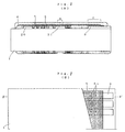
- Fig. 1 shows the printed circuit board which is the first embodiment of this invention.
- Fig. 1 (A) shows the X-X' cross section.
- Fig. 1 (B) shows the plan.
- the circuit pattern shown in the figure is formed on the surface of the substrate 1.
- the circuit pattern includes signal pattern 20, ground pattern 21, and power supply pattern not shown in the figure.
- a connector land 8 to which the connector is connected is formed, in addition to this circuit pattern, at the end of substrate 1 with a larger area than that of ordinary connector land 8a,at the same time when the circuit pattern is formed.
- These patterns are formed by the well known photolithography.
- the undercoat layer 4 is formed, leaving uncovered a partial area A of the ground pattern 21. It is desirable that the area A where the ground pattern 21 is exposed is formed at several places on the substrate. At least one place is required.
- This undercoat layer 4 is formed by screen printing so that the upper side of connector land 8 is also covered together with the above-mentioned circuit pattern.
- the conductive layer 5 for shield is formed thereon. This conductive layer 5 is also formed by printing on the undercoat layer 4 so as to cover the upper side of connector land 8 together with the above-mentioned circuit pattern. In this example of embodiment this conductive layer 5 is made of paste.
- an overcoat layer 6 made of insulation resin material is formed on the whole upper surface of conductive layer 5.
- This overcoat layer 6 can be made of the same material as that of undercoat layer 4. It is easily formed by printing together with conductive layer 5 and undercoat layer 4.
- the area C where the connector land 8 and the conductive layer 5 located above it overlap on respective sides of undercoat layer 4, composes a capacitor. Since the thickness of the undercoat layer 4 is about 20 to 40 ⁇ m, the capacitance necessary for a bypass capacitor can be obtained if the area C has an appropriate area. Accordingly, the required bypass capacitor can be formed by composing the capacitor section as the area C shown in Fig. 1 (A) for all the connector lands connected to each signal pattern without solder-connecting the bypass capacitor as a discrete part.
- inductance L of the lead wire can be calculated by using the formula (1) assuming that length and diameter of two lead wires (metal wires) of bypass capacitor are 5 mm and 0.6 mm, respectively.
- L ⁇ l 2 (ln 2l r -1) [H] where
- inductance of one lead wire is:
- the series impedance Z 1 2 ⁇ fc 2 ⁇ fL x 2
- the impedance Z can be obtained from the formula (3). .
- the abscissa shows frequency f(MHz) whereas the ordinate shows the absolute value of impedance
- represent the frequency characteristics of impedance, respectively of the conventional example and of the embodiment.
- represent the frequency characteristics of the absolute value of impedance, respectively caused by caused by the electrostatic capacitance of the bypass capacitor and caused by inductance of the lead wire of the conventional example.
- the bypass capacitor does not have inductance. Accordingly, the impedance decreases as the frequency increases. Therefore this feature is most useful for the bypass capacitor.
- Fig. 1 represents a bypass capacitor between the connector 1and 8 and the conductive layer 5. Since the power terminal land is formed at the end of substrate 1, a bypass capacitor can be formed between this power terminal land and the conductive layer 5. The effect can be also enhanced by additionally using a discrete bypass capacitor.
- the conductive layer 5 is connected to the ground pattern 21. It is allowed to connect the conductive layer 5 to the power supply pattern in place of ground pattern 21.
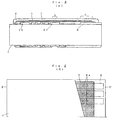
- Fig. 2 (A) and Fig. 2 (B) show the examples. That is, when the undercoat layer 4 is formed by printing, a part of the power supply pattern 22 is left uncovered and the conductive layer 5 is formed by printing thereon, so that the potential of the conductive layer 5 can be set to the power supply voltage. As a result, in the area C a bypass capacitor is formed between the connector land 8 and the power source. Nevertheless, since the power supply impedance can be ignored at high frequency, the same high frequency noise (radiation noise) suppression effect as that obtained in the example of embodiment shown in Fig. 1 can be obtained. In the embodiment shown in Fig. 2, the bypass capacitor can be also formed between the ground terminal land and the conductive layer.
- the same effect can be obtained by connecting the conductive layer 5 either to the ground pattern 21 or to the power supply pattern 22. Therefore, in the case when the power supply pattern and ground pattern is restricted in the layout of substrate, it is possible to select for connection to the conductive layer 5 the more effective pattern from the viewpoint of high frequency noise suppression effect.
- bypass capacitor requires merely an extension of the insulation layer and the conductive layer. Therefore there is no need to increase the printing process. Accordingly, a good effect is obtained, and production cost does not increase.
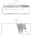
- Fig. 4 (A) and Fig. 4 (B) show a printed circuit board which is another embodiment of this invention.
- the circuit pattern 2 shown in the figure is first formed on the surface of the substrate 1.
- the circuit pattern includes signal patterns 20 and 20', a ground pattern 21 and a power supply pattern not shown in the figure. These patterns are formed by using well known photolithography.
- the first undercoat layer 4 is formed, leaving uncovered the partial area D of signal pattern 20' and the partial area A of ground pattern 21. It is desirable that the area A where the ground pattern 21 is exposed is formed on several places of substrate. At least one place is required.
- the first conductive layer 5 for shield is formed by screen printing thereon.
- the first conductive layer 5 is formed on the upper surface of the first undercoat layer 4 in a region on the left as shown in the figure, namely in the region not covering the upper part of signal pattern 20'.
- the reason why the first conductive layer 5 is formed so that the upper part of signal pattern 20' is not covered is that contact of the first conductive layer 5 to a second conductive layer 9 on the signal pattern 20' must be avoided, as stated later.
- the first conductive layer 5 mentioned above is made of copper paste.
- the first overcoat layer 6 made of resin insulation material is formed so as to cover the first conductive layer 5.
- the first overcoat layer 6 can be made of the same material as that of undercoat layer 4. It can be easily formed by printing together with the first conductive layer 5 and undercoat layer 4.
- the second conductive layer 9 is formed in the area above the above-mentioned signal pattern 20'. This second conductive layer 9 is formed by screen printing, using the same material as that of the first conductive layer 5. Accordingly, it is connected to the signal pattern 20' in the area D.
- the region of formation of the second conductive layer 9 is chosen so that part of it (left side in the figure) is located overlapping a part of the first conductive layer 5.
- the second conductive layer 9 overlaps the first conductive layer 5 in the area C.
- the first overcoat layer 6 is sandwiched between the second conductive layer 9 and the first conductive layer 5, thereby forming a capacitor in this part.
- the second overcoat layer 10 is formed on the whole surface of substrate. This second overcoat layer 10 is formed by using the same printing process and the same material as those applied for the first overcoat layer 6 and undercoat layer 4.
- the first conductive layer 5 and the second conductive layer 9 in the area C overlap each other through the first overcoat layer 6, and a capacitor is formed in this part.
- the first conductive layer 5 is connected to the ground pattern 21 in the area A
- the second conductive layer 9 is connected to the signal pattern 20' in the area D. Therefore the capacitor formed in this area C serves as a bypass capacitor connected to the signal pattern 20' Since the thickness of the first overcoat layer 6 is extremely small (20 to 40 ⁇ m), the bypass capacitor which is formed in the area C has a sufficient capacitance to act as the bypass capacitor. Since, moreover, the overlap area of first conductive layer 5 and second conductive layer 9 can be easily changed when designing the screen mesh layout, a bypass capacitor having a small capacitance or a bypass capacitor having a large capacitance can be easily formed.
- bypass capacitor is formed between signal pattern 20' and ground pattern 21. It is also allowed to connect the first conductive layer 5 to the power supply pattern in place of ground pattern 21. Even in this configuration the composition of area C does not change. A bypass capacitor having the required capacitance can be obtained.
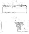
- Fig. 5(A) and Fig. 5(B) show a bypass capacitor which is formed between the power supply pattern and the ground pattern.
- the difference in configuration between printed circuit boards shown in Fig. 4(A) and Fig. 4(B), and in Fig. 5(A) and Fig. 5(B), is that the second conductive layer 9 of printed circuit board is connected to the power supply pattern 22, not to the signal pattern 20'. This is the only difference. In all other respects they are the same. It is also allowed to connect the first conductive layer 5 to the power supply pattern 22 and the second conductive layer 9 to the ground pattern 21. In either case a bypass capacitor to absorb the high frequency noise between the power supply source and the ground pattern is formed in the area C.
- the same radiation noise suppression effect as that obtained on the conventional EMI-prevented printed circuit board can be obtained owing to existence of first conductive layer.
- a bypass capacitor can be formed in a part where the first conductive layer overlaps the second conductive layer. Therefore the radiation noise suppression effect is ensured and and at the same time the size of printed circuit board can be reduced. Since lead wires are not required, inductance does not occur, so that excellent frequency characteristics of the bypass capacitor can be obtained.
- all the insulation layers and conductive layers can be formed by using the known screen printing process, the production process can be simple.
- Fig. 6 shows a printed circuit board which is another embodiment of this invention.
- the circuit pattern as shown in the figure is formed on the surface of substrate 1 made of insulation material such as epoxy resin, phenol resin, glass fiber or ceramics.
- the circuit pattern includes the signal pattern 20, and the ground pattern 21. These patterns are formed by well known photolithography.
- the undercoat layer 4 is formed, leaving uncovered partial area A of the ground pattern 21. It is desirable that the exposed area A of the ground pattern 21 is formed on several places on the substrate. It must be formed at least on one place.
- the conductive paste layer 5 for shield is formed by screen print. In this example of embodiment this conductive paste layer 5 is made of copper paste and covers almost the whole area of the undercoat layer 4.
- the conductive paste layer 5 After the conductive paste layer 5 is applied, it is heated to cure. And then the overcoat layer 6 made of insulation resin material is formed on the whole upper surface of the substrate 1.
- This overcoat layer 6 can be made of the same material as that of the undercoat layer 4. It can be easily formed by the printing process together with the conductive paste layer 5 and the undercoat layer 4.
- the signal pattern 20 is wholly arranged so that the interior angle of bent part B is set to approx. 135°. If the pattern of each signal line is set to 135° as shown in the figure, signal reflection at the bent part B is reduced, so that increase of high frequency impedance is prevented. Accordingly, as compared to conventional arrangement where the bent part B is set at a right angle, generation of radiation noise (high frequency noise) is less. Although suppression of high frequency noise generation at one bent part B is insignificant, significant effect is obtained if the effects of all bent parts are combined since one substrate usually has many signal line bent parts.
- Fig. 7 shows a graph where abscissa shows frequency and ordinate shows electric field strength. It compares the conventional printed circuit board "a" where the bent part B is at a right angle, the printed circuit board "b” which is the embodiment shown in Fig. 6 (B) where the interior angle of the bent part B is set to approx. 135°, and the printed circuit board "c" which is the embodiment shown in Fig. 6 (C) where a radius is given to the bent part B and the interior angle is set to approx. 135°.
- excellent magnetic wave suppression effect can be obtained if the printed circuit boards "b” and "c" of the embodiment of this invention are used.
- the graph of printed circuit board "d" which is the embodiment shown in Fig.
Landscapes
- Engineering & Computer Science (AREA)
- Microelectronics & Electronic Packaging (AREA)
- Physics & Mathematics (AREA)
- Electromagnetism (AREA)
- Structure Of Printed Boards (AREA)
- Shielding Devices Or Components To Electric Or Magnetic Fields (AREA)
Claims (12)
- Gedruckte Leiterplatte mit:einem Substrat (1);einem auf dem Substrat (1) geformten Leitungsmuster (2), das ein Signalleitungsmuster (20, 20') und ein weiteres Muster, welches (i) ein Stromzuführleitungsmuster (22) oder (ii) ein Masseleitungsmuster (21) ist, umfaßt;einer Isolierschicht (4), die auf dem Substrat (1) über dem Leitungsmuster (2) ausgebildet ist; undeiner leitfähigen Schicht (5) zur Verbindung mit Masse oder einem Stromzuführungspotential, die auf der Isolierschicht (4) ausgebildet ist;
dadurch gekennzeichnet, daß(a) die Isolierschicht (4) so ausgebildet ist, daß sie einen Teil des Leitungsmusters (2) mit Ausnahme mindestens eines Teils des weiteren Musters abdeckt; und(b) die leitfähige Schicht (5) so ausgebildet ist, daß sie mit einem nichtisolierten Teil des weiteren Musters verbunden ist, und einen leitfähigen Teil (8,9) überlappt, der zusätzlich zu dem Leitungsmuster (2) ausgebildet ist und der mit einem anderen Teil des Leitungsmusters (2) als dem weiteren Muster verbunden ist, um einen Nebenschlußkondensator zu bilden. - Gedruckte Leiterplatte nach Anspruch 1,
wobei der leitfähige Teil eine Leiterbahn (8) ist, die auf dem Substrat (1) ausgebildet ist. - Gedruckte Leiterplatte nach Anspruch 2,
wobei die Leiterbahn eine Signalverbindungsbahn ist, an die ein Signalleiter angeschlossen ist. - Gedruckte Leiterplatte nach Anspruch 2,
wobei die Leiterbahn eine Energieversorgungsanschlußbahn ist, mit der ein Energieversorgungsleiter verbunden ist, und das weitere Muster das Masseleitungsmuster (21) ist. - Gedruckte Leiterplatte nach Anspruch 2,
wobei die Leiterbahn eine Masseanschlußbahn ist, die mit einem Masseleiter verbunden ist, und das weitere Muster ein Energieversorgungsleitungsmuster (22) ist. - Gedruckte Leiterplatte nach Anspruch 1,
wobei eine zweite Isolierschicht (6) auf der leitfähigen Schicht (5) ausgebildet ist,der leitfähige Teil (9) auf der zweiten Isolierschicht (6) ausgebildet ist und die leitfähige Schicht (5) so überlappt, daß der Nebenschlußkondensator gebildet wird, undder leitfähige Teil (9) mit dem Signalleitungsmuster (20') verbunden ist. - Gedruckte Leiterplatte nach Anspruch 1,
wobei eine zweite Isolierschicht (6) auf der leitfähigen Schicht (5) ausgebildet ist,der leitfähige Teil (9) auf der zweiten Isolierschicht (6) ausgebildet ist und die leitfähige Schicht (5) so überlappt, daß der Nebenschlußkondensator gebildet wird, undder leitfähige Teil (9) mit dem Energieversorgungsleitungsmuster (22) verbunden ist und das weitere Muster das Masseleitungsmuster (21) ist. - Gedruckte Leiterplatte nach Anspruch 1,
wobei eine zweite Isolierschicht (6) auf der leitfähigen Schicht (5) ausgebildet ist,der leitfähige Teil (9) auf der zweiten Isolierschicht (6) ausgebildet ist und die leitfähige Schicht (5) so überlappt, daß der Nebenschlußkondensator gebildet wird, undder leitfähige Teil (9) mit dem Masseleitungsmuster (21) verbunden ist und das weitere Muster das Energieversorgungsleitungsmuster (22) ist. - Gedruckte Leiterplatte nach einem der vorstehenden Ansprüche,
wobei ein Innenwinkel eines gebogenen Teils des Signalleitungsmusters (20) in dem Leitungsmuster (2) einen Winkel von ungefähr 135° oder mehr aufweist. - Gedruckte Leiterplatte nach einem der Ansprüche 1 bis 9, wobei ein gebogener Teil des Signalleitungsmusters (20) in dem Leitungsmuster (2) die Form eines Kreisbogens hat.
- Verfahren zum Herstellen einer gedruckten Leiterplatte mit den Schritten:(a) Aufdrucken einer Schaltung (2), die ein Energieversorgungsleitungsmuster (22) oder ein Masseleitungsmuster (21) aufweist, auf ein Substrat (1);(b) Ausbilden einer Isolierschicht (4) auf der gedruckten Schaltung (2); und(c) Ausbilden einer leitfähigen Schicht (5) auf der Isolierschicht (4),
dadurch gekennzeichnet, daß die Isolierschicht auf mindestens einem Teil des Musters (21 oder 22) der gedruckten Schaltung nicht ausgebildet ist und die leitfähige Schicht (5) die gedruckte Schaltung (2) an dem Muster (21 oder 22) kontaktiert und einen leitfähigen Teil (8, 9) überlappt, der zusätzlich zu der gedruckten Schaltung (2) ausgebildet ist und der mit einem anderen Muster der gedruckten Schaltung (2) als demjenigen Muster, das von der leitfähigen Schicht kontaktiert wird, verbunden ist, um einen Nebenschlußkondensator zu bilden. - Verfahren nach Anspruch 11,
wobei die Isolierschicht (4) und die leitfähige Schicht (5) durch ein Siebdruckverfahren ausgebildet werden.
Applications Claiming Priority (19)
| Application Number | Priority Date | Filing Date | Title |
|---|---|---|---|
| JP40838/89 | 1989-02-21 | ||
| JP4083789 | 1989-02-21 | ||
| JP4083789 | 1989-02-21 | ||
| JP4083689 | 1989-02-21 | ||
| JP4083689 | 1989-02-21 | ||
| JP19218/89U | 1989-02-21 | ||
| JP40836/89 | 1989-02-21 | ||
| JP1921989 | 1989-02-21 | ||
| JP1922089 | 1989-02-21 | ||
| JP1921889U | 1989-02-21 | ||
| JP1921889 | 1989-02-21 | ||
| JP4083889 | 1989-02-21 | ||
| JP19220/89U | 1989-02-21 | ||
| JP19219/89U | 1989-02-21 | ||
| JP1921989U | 1989-02-21 | ||
| JP40837/89 | 1989-02-21 | ||
| JP4083889 | 1989-02-21 | ||
| JP1922089U | 1989-02-21 | ||
| EP90301612A EP0384644B1 (de) | 1989-02-21 | 1990-02-15 | Gedruckte Leiterplatte |
Related Parent Applications (2)
| Application Number | Title | Priority Date | Filing Date |
|---|---|---|---|
| EP90301612A Division EP0384644B1 (de) | 1989-02-21 | 1990-02-15 | Gedruckte Leiterplatte |
| EP90301612.9 Division | 1990-02-15 |
Publications (3)
| Publication Number | Publication Date |
|---|---|
| EP0631460A2 EP0631460A2 (de) | 1994-12-28 |
| EP0631460A3 EP0631460A3 (de) | 1995-07-26 |
| EP0631460B1 true EP0631460B1 (de) | 2000-04-26 |
Family
ID=27548844
Family Applications (3)
| Application Number | Title | Priority Date | Filing Date |
|---|---|---|---|
| EP90301612A Expired - Lifetime EP0384644B1 (de) | 1989-02-21 | 1990-02-15 | Gedruckte Leiterplatte |
| EP94202846A Expired - Lifetime EP0631460B1 (de) | 1989-02-21 | 1990-02-15 | Gedruckte Schaltung |
| EP94202845A Expired - Lifetime EP0633715B1 (de) | 1989-02-21 | 1990-02-15 | Gedruckte Schaltungsplatte |
Family Applications Before (1)
| Application Number | Title | Priority Date | Filing Date |
|---|---|---|---|
| EP90301612A Expired - Lifetime EP0384644B1 (de) | 1989-02-21 | 1990-02-15 | Gedruckte Leiterplatte |
Family Applications After (1)
| Application Number | Title | Priority Date | Filing Date |
|---|---|---|---|
| EP94202845A Expired - Lifetime EP0633715B1 (de) | 1989-02-21 | 1990-02-15 | Gedruckte Schaltungsplatte |
Country Status (7)
| Country | Link |
|---|---|
| US (2) | US5341274A (de) |
| EP (3) | EP0384644B1 (de) |
| KR (1) | KR0123805B1 (de) |
| AU (1) | AU636129B2 (de) |
| CA (1) | CA2010128C (de) |
| DE (3) | DE69019030T2 (de) |
| FI (1) | FI113937B (de) |
Families Citing this family (32)
| Publication number | Priority date | Publication date | Assignee | Title |
|---|---|---|---|---|
| JPH073660Y2 (ja) * | 1989-02-27 | 1995-01-30 | 任天堂株式会社 | Emi対策用回路基板 |
| US4904968A (en) * | 1989-04-07 | 1990-02-27 | Tektronix, Inc. | Circuit board configuration for reducing signal distortion |
| JP3260941B2 (ja) * | 1993-06-18 | 2002-02-25 | 株式会社日立製作所 | 多層配線基板および多層配線基板の製造方法 |
| US5639989A (en) * | 1994-04-19 | 1997-06-17 | Motorola Inc. | Shielded electronic component assembly and method for making the same |
| US5500789A (en) * | 1994-12-12 | 1996-03-19 | Dell Usa, L.P. | Printed circuit board EMI shielding apparatus and associated methods |
| JP3368451B2 (ja) * | 1995-03-17 | 2003-01-20 | 富士通株式会社 | 回路基板の製造方法と回路検査装置 |
| SE506941C2 (sv) * | 1995-03-31 | 1998-03-02 | Ericsson Telefon Ab L M | Kretskort med interferensskärmande skikt |
| US5981043A (en) * | 1996-04-25 | 1999-11-09 | Tatsuta Electric Wire And Cable Co., Ltd | Electroconductive coating composition, a printed circuit board fabricated by using it and a flexible printed circuit assembly with electromagnetic shield |
| JP3581971B2 (ja) * | 1996-05-22 | 2004-10-27 | 株式会社ボッシュオートモーティブシステム | 車載用コントロールユニットのemi用接地構造 |
| KR100227741B1 (ko) * | 1996-11-29 | 1999-11-01 | 윤종용 | 스텐바이 전원을 가진 전자제품 |
| JP2004506309A (ja) | 1997-12-31 | 2004-02-26 | エルパック(ユーエスエー)、インコーポレイテッド | モールドされた電子パッケージ、製作方法およびシールディング方法 |
| US6160714A (en) | 1997-12-31 | 2000-12-12 | Elpac (Usa), Inc. | Molded electronic package and method of preparation |
| JP3501674B2 (ja) * | 1999-04-21 | 2004-03-02 | 日本電気株式会社 | プリント回路基板特性評価装置、プリント回路基板特性評価方法、及び記憶媒体 |
| JP3455498B2 (ja) * | 2000-05-31 | 2003-10-14 | 株式会社東芝 | プリント基板および情報処理装置 |
| US6618787B2 (en) * | 2000-12-14 | 2003-09-09 | Hewlett-Packard Development Company, L.P. | Computer printed circuit system board with LVD SCSI device direct connector |
| US6614662B2 (en) * | 2000-12-14 | 2003-09-02 | Hewlett-Packard Development Company, L.P. | Printed circuit board layout |
| US6753746B2 (en) * | 2001-11-07 | 2004-06-22 | Compeq Manufacturing Co., Ltd. | Printed circuit board having jumper lines and the method for making said printed circuit board |
| US6717485B2 (en) * | 2002-02-19 | 2004-04-06 | Hewlett-Packard Development Company, L.P. | Interference signal decoupling using a board-level EMI shield that adheres to and conforms with printed circuit board component and board surfaces |
| AU2003265440A1 (en) * | 2002-08-14 | 2004-03-03 | Honeywell International, Inc. | Method and apparatus for reducing electromagnetic emissions from electronic circuits |
| DE10305520A1 (de) * | 2003-02-11 | 2004-08-19 | Robert Bosch Gmbh | Vorrichtung und Verfahren zur Dämpfung von Hohlraumresonanzen in einer mehrschichtigen Trägereinrichtung |
| DE102006027748A1 (de) * | 2006-06-16 | 2007-12-20 | Robert Bosch Gmbh | Leiterplatte und Verfahren zur Herstellung einer lötfreien elektrischen Verbindung |
| JP4877791B2 (ja) | 2007-01-26 | 2012-02-15 | 日東電工株式会社 | 配線回路基板 |
| US8276268B2 (en) * | 2008-11-03 | 2012-10-02 | General Electric Company | System and method of forming a patterned conformal structure |
| US8373317B2 (en) * | 2009-05-04 | 2013-02-12 | Ingersoll Rand Company | RFI suppression system and method of mounting for DC cordless tools |
| TWI387407B (zh) * | 2009-06-10 | 2013-02-21 | Htc Corp | 軟式印刷電路板其及組成方法 |
| DE102009044608A1 (de) | 2009-11-20 | 2011-05-26 | Webasto Ag | Heizgerät |
| US9545043B1 (en) * | 2010-09-28 | 2017-01-10 | Rockwell Collins, Inc. | Shielding encapsulation for electrical circuitry |
| CN203015272U (zh) * | 2012-12-21 | 2013-06-19 | 奥特斯(中国)有限公司 | 印制电路板 |
| JP2017118015A (ja) * | 2015-12-25 | 2017-06-29 | 株式会社トーキン | 電子装置及び電磁干渉抑制体の配置方法 |
| US10694620B1 (en) * | 2019-04-02 | 2020-06-23 | Microsoft Technology Licensing, Llc | Method and apparatus for circuit board noise shielding and grounding |
| USD980842S1 (en) | 2020-08-24 | 2023-03-14 | Intel Corporation | Shielding for circuit board |
| CN117256203A (zh) * | 2022-02-03 | 2023-12-19 | 微软技术许可有限责任公司 | 用于印刷电路板的印刷去耦平面 |
Family Cites Families (20)
| Publication number | Priority date | Publication date | Assignee | Title |
|---|---|---|---|---|
| DE1936899A1 (de) * | 1969-07-19 | 1971-02-04 | Siemens Ag | Baugruppentraeger fuer Steuer- bzw. Regelanlagen |
| US3740678A (en) * | 1971-03-19 | 1973-06-19 | Ibm | Strip transmission line structures |
| DE2260195A1 (de) * | 1972-12-08 | 1974-06-12 | Michael M Dipl Ing Iloff | Leiterplatte fuer elektrische schaltungen |
| FR2212740B1 (de) * | 1972-12-28 | 1977-02-25 | Honeywell Bull | |
| EP0082216B1 (de) * | 1981-12-23 | 1985-10-09 | Ibm Deutschland Gmbh | Mehrschichtiges, keramisches Substrat für integrierte Halbleiterschaltungen mit mehreren Metallisierungsebenen |
| FR2527039A1 (fr) * | 1982-05-14 | 1983-11-18 | Inf Milit Spatiale Aeronaut | Dispositif de protection d'un dispositif electronique contre les tensions engendrees par un champ electromagnetique |
| JPS6016701A (ja) * | 1983-07-08 | 1985-01-28 | Nec Corp | マイクロ波プリント板回路 |
| US4723197A (en) * | 1985-12-16 | 1988-02-02 | National Semiconductor Corporation | Bonding pad interconnection structure |
| US4724040A (en) * | 1986-01-14 | 1988-02-09 | Asahi Chemical Research Laboratory Co., Ltd. | Method for producing electric circuits on a base boad |
| FR2593346B1 (fr) * | 1986-01-17 | 1990-05-25 | Nec Corp | Substrat de cablage utilisant une ceramique comme isolant |
| US5043526A (en) * | 1986-03-13 | 1991-08-27 | Nintendo Company Ltd. | Printed circuit board capable of preventing electromagnetic interference |
| CA1261481A (en) * | 1986-03-13 | 1989-09-26 | Kazumasa Eguchi | Printed circuit board capable of preventing electromagnetic interference |
| US4717988A (en) * | 1986-05-05 | 1988-01-05 | Itt Defense Communications Division Of Itt Corporation | Universal wafer scale assembly |
| US4770921A (en) * | 1986-09-11 | 1988-09-13 | Insulating Materials Incorporated | Self-shielding multi-layer circuit boards |
| JPS6453498A (en) * | 1987-05-15 | 1989-03-01 | Sanki Eng Co Ltd | Multilayer interconnection board |
| US4963697A (en) * | 1988-02-12 | 1990-10-16 | Texas Instruments Incorporated | Advanced polymers on metal printed wiring board |
| US4927983A (en) * | 1988-12-16 | 1990-05-22 | International Business Machines Corporation | Circuit board |
| JP2631548B2 (ja) * | 1989-03-15 | 1997-07-16 | 日本シイエムケイ株式会社 | シールド層を備えるプリント配線板 |
| US5003273A (en) * | 1989-12-04 | 1991-03-26 | Itt Corporation | Multilayer printed circuit board with pseudo-coaxial transmission lines |
| US5285017A (en) * | 1991-12-31 | 1994-02-08 | Intel Corporation | Embedded ground plane and shielding structures using sidewall insulators in high frequency circuits having vias |
-
1990
- 1990-02-06 FI FI900580A patent/FI113937B/fi not_active IP Right Cessation
- 1990-02-07 AU AU49200/90A patent/AU636129B2/en not_active Ceased
- 1990-02-08 US US07/477,322 patent/US5341274A/en not_active Expired - Fee Related
- 1990-02-15 DE DE69019030T patent/DE69019030T2/de not_active Expired - Fee Related
- 1990-02-15 EP EP90301612A patent/EP0384644B1/de not_active Expired - Lifetime
- 1990-02-15 EP EP94202846A patent/EP0631460B1/de not_active Expired - Lifetime
- 1990-02-15 EP EP94202845A patent/EP0633715B1/de not_active Expired - Lifetime
- 1990-02-15 DE DE69033784T patent/DE69033784T2/de not_active Expired - Fee Related
- 1990-02-15 CA CA002010128A patent/CA2010128C/en not_active Expired - Fee Related
- 1990-02-15 DE DE69033522T patent/DE69033522T2/de not_active Expired - Fee Related
- 1990-02-20 KR KR1019900002040A patent/KR0123805B1/ko not_active IP Right Cessation
-
1994
- 1994-03-30 US US08/220,257 patent/US5449863A/en not_active Expired - Fee Related
Also Published As
| Publication number | Publication date |
|---|---|
| EP0633715A2 (de) | 1995-01-11 |
| US5341274A (en) | 1994-08-23 |
| DE69033784D1 (de) | 2001-10-04 |
| EP0631460A2 (de) | 1994-12-28 |
| FI113937B (fi) | 2004-06-30 |
| DE69033784T2 (de) | 2002-07-04 |
| CA2010128C (en) | 1996-03-19 |
| EP0633715B1 (de) | 2001-08-29 |
| CA2010128A1 (en) | 1990-08-21 |
| EP0384644A1 (de) | 1990-08-29 |
| KR900013820A (ko) | 1990-09-06 |
| DE69033522T2 (de) | 2000-12-21 |
| EP0384644B1 (de) | 1995-05-03 |
| FI900580A0 (fi) | 1990-02-06 |
| KR0123805B1 (ko) | 1997-12-04 |
| DE69033522D1 (de) | 2000-05-31 |
| US5449863A (en) | 1995-09-12 |
| DE69019030T2 (de) | 1995-12-21 |
| AU636129B2 (en) | 1993-04-22 |
| EP0633715A3 (de) | 1995-07-26 |
| EP0631460A3 (de) | 1995-07-26 |
| DE69019030D1 (de) | 1995-06-08 |
| AU4920090A (en) | 1990-08-30 |
Similar Documents
| Publication | Publication Date | Title |
|---|---|---|
| EP0631460B1 (de) | Gedruckte Schaltung | |
| EP0880150B1 (de) | Gedruckte Leiterplatte | |
| US5357050A (en) | Apparatus and method to reduce electromagnetic emissions in a multi-layer circuit board | |
| US5334800A (en) | Flexible shielded circuit board | |
| US6150895A (en) | Circuit board voltage plane impedance matching | |
| US6288906B1 (en) | Multiple layer printed circuit board having power planes on outer layers | |
| JP3214472B2 (ja) | 多層プリント回路基板 | |
| JP2970660B1 (ja) | プリント基板 | |
| JP3234556B2 (ja) | 回路ボードの信号線路インピーダンスの制御方法及び装置 | |
| US5466893A (en) | Printed circuit board having enhanced EMI suppression | |
| US5043526A (en) | Printed circuit board capable of preventing electromagnetic interference | |
| US5912597A (en) | Printed circuit board | |
| US5140110A (en) | Printed circuit board capable of preventing electromagnetic interference | |
| JPH08204377A (ja) | 遮蔽体 | |
| JP3116870B2 (ja) | シールド線付き伝送線路 | |
| JPH073660Y2 (ja) | Emi対策用回路基板 | |
| US5880938A (en) | Circuit board with screening arrangement against electromagnetic interference | |
| AU648943B2 (en) | Printed circuit board | |
| JPH0682890B2 (ja) | Emi対策用回路基板とその製造方法 | |
| JPH04261097A (ja) | 多層プリント基板 | |
| JP2613368B2 (ja) | プリント回路基板およびその製造方法 | |
| JP3102415B2 (ja) | 伝送線路 | |
| JPH02103990A (ja) | プリント配線板 | |
| JPS6315498A (ja) | Emi対策用回路基板 | |
| JPH02241097A (ja) | プリント配線板 |
Legal Events
| Date | Code | Title | Description |
|---|---|---|---|
| PUAI | Public reference made under article 153(3) epc to a published international application that has entered the european phase |
Free format text: ORIGINAL CODE: 0009012 |
|
| AC | Divisional application: reference to earlier application |
Ref document number: 384644 Country of ref document: EP |
|
| AK | Designated contracting states |
Kind code of ref document: A2 Designated state(s): DE FR GB IT SE |
|
| PUAL | Search report despatched |
Free format text: ORIGINAL CODE: 0009013 |
|
| AK | Designated contracting states |
Kind code of ref document: A3 Designated state(s): DE FR GB IT SE |
|
| 17P | Request for examination filed |
Effective date: 19951012 |
|
| GRAG | Despatch of communication of intention to grant |
Free format text: ORIGINAL CODE: EPIDOS AGRA |
|
| 17Q | First examination report despatched |
Effective date: 19990324 |
|
| GRAG | Despatch of communication of intention to grant |
Free format text: ORIGINAL CODE: EPIDOS AGRA |
|
| GRAG | Despatch of communication of intention to grant |
Free format text: ORIGINAL CODE: EPIDOS AGRA |
|
| GRAH | Despatch of communication of intention to grant a patent |
Free format text: ORIGINAL CODE: EPIDOS IGRA |
|
| GRAH | Despatch of communication of intention to grant a patent |
Free format text: ORIGINAL CODE: EPIDOS IGRA |
|
| GRAA | (expected) grant |
Free format text: ORIGINAL CODE: 0009210 |
|
| AC | Divisional application: reference to earlier application |
Ref document number: 384644 Country of ref document: EP |
|
| AK | Designated contracting states |
Kind code of ref document: B1 Designated state(s): DE FR GB IT SE |
|
| ET | Fr: translation filed | ||
| REF | Corresponds to: |
Ref document number: 69033522 Country of ref document: DE Date of ref document: 20000531 |
|
| ITF | It: translation for a ep patent filed | ||
| PLBE | No opposition filed within time limit |
Free format text: ORIGINAL CODE: 0009261 |
|
| STAA | Information on the status of an ep patent application or granted ep patent |
Free format text: STATUS: NO OPPOSITION FILED WITHIN TIME LIMIT |
|
| 26N | No opposition filed | ||
| REG | Reference to a national code |
Ref country code: GB Ref legal event code: IF02 |
|
| PGFP | Annual fee paid to national office [announced via postgrant information from national office to epo] |
Ref country code: SE Payment date: 20040204 Year of fee payment: 15 |
|
| PGFP | Annual fee paid to national office [announced via postgrant information from national office to epo] |
Ref country code: FR Payment date: 20040210 Year of fee payment: 15 |
|
| PGFP | Annual fee paid to national office [announced via postgrant information from national office to epo] |
Ref country code: GB Payment date: 20040211 Year of fee payment: 15 |
|
| PGFP | Annual fee paid to national office [announced via postgrant information from national office to epo] |
Ref country code: DE Payment date: 20040226 Year of fee payment: 15 |
|
| PG25 | Lapsed in a contracting state [announced via postgrant information from national office to epo] |
Ref country code: IT Free format text: LAPSE BECAUSE OF NON-PAYMENT OF DUE FEES;WARNING: LAPSES OF ITALIAN PATENTS WITH EFFECTIVE DATE BEFORE 2007 MAY HAVE OCCURRED AT ANY TIME BEFORE 2007. THE CORRECT EFFECTIVE DATE MAY BE DIFFERENT FROM THE ONE RECORDED. Effective date: 20050215 Ref country code: GB Free format text: LAPSE BECAUSE OF NON-PAYMENT OF DUE FEES Effective date: 20050215 |
|
| PG25 | Lapsed in a contracting state [announced via postgrant information from national office to epo] |
Ref country code: SE Free format text: LAPSE BECAUSE OF NON-PAYMENT OF DUE FEES Effective date: 20050216 |
|
| PG25 | Lapsed in a contracting state [announced via postgrant information from national office to epo] |
Ref country code: DE Free format text: LAPSE BECAUSE OF NON-PAYMENT OF DUE FEES Effective date: 20050901 |
|
| EUG | Se: european patent has lapsed | ||
| GBPC | Gb: european patent ceased through non-payment of renewal fee |
Effective date: 20050215 |
|
| PG25 | Lapsed in a contracting state [announced via postgrant information from national office to epo] |
Ref country code: FR Free format text: LAPSE BECAUSE OF NON-PAYMENT OF DUE FEES Effective date: 20051031 |
|
| REG | Reference to a national code |
Ref country code: FR Ref legal event code: ST Effective date: 20051031 |