EP0628362A2 - Outil de pressage - Google Patents
Outil de pressage Download PDFInfo
- Publication number
- EP0628362A2 EP0628362A2 EP94110655A EP94110655A EP0628362A2 EP 0628362 A2 EP0628362 A2 EP 0628362A2 EP 94110655 A EP94110655 A EP 94110655A EP 94110655 A EP94110655 A EP 94110655A EP 0628362 A2 EP0628362 A2 EP 0628362A2
- Authority
- EP
- European Patent Office
- Prior art keywords
- press
- jaws
- pressing
- abutment
- tool according
- Prior art date
- Legal status (The legal status is an assumption and is not a legal conclusion. Google has not performed a legal analysis and makes no representation as to the accuracy of the status listed.)
- Granted
Links
Images
Classifications
-
- B—PERFORMING OPERATIONS; TRANSPORTING
- B21—MECHANICAL METAL-WORKING WITHOUT ESSENTIALLY REMOVING MATERIAL; PUNCHING METAL
- B21D—WORKING OR PROCESSING OF SHEET METAL OR METAL TUBES, RODS OR PROFILES WITHOUT ESSENTIALLY REMOVING MATERIAL; PUNCHING METAL
- B21D39/00—Application of procedures in order to connect objects or parts, e.g. coating with sheet metal otherwise than by plating; Tube expanders
- B21D39/04—Application of procedures in order to connect objects or parts, e.g. coating with sheet metal otherwise than by plating; Tube expanders of tubes with tubes; of tubes with rods
- B21D39/046—Connecting tubes to tube-like fittings
-
- B—PERFORMING OPERATIONS; TRANSPORTING
- B21—MECHANICAL METAL-WORKING WITHOUT ESSENTIALLY REMOVING MATERIAL; PUNCHING METAL
- B21D—WORKING OR PROCESSING OF SHEET METAL OR METAL TUBES, RODS OR PROFILES WITHOUT ESSENTIALLY REMOVING MATERIAL; PUNCHING METAL
- B21D39/00—Application of procedures in order to connect objects or parts, e.g. coating with sheet metal otherwise than by plating; Tube expanders
- B21D39/04—Application of procedures in order to connect objects or parts, e.g. coating with sheet metal otherwise than by plating; Tube expanders of tubes with tubes; of tubes with rods
-
- B—PERFORMING OPERATIONS; TRANSPORTING
- B25—HAND TOOLS; PORTABLE POWER-DRIVEN TOOLS; MANIPULATORS
- B25B—TOOLS OR BENCH DEVICES NOT OTHERWISE PROVIDED FOR, FOR FASTENING, CONNECTING, DISENGAGING, OR HOLDING
- B25B27/00—Hand tools, specially adapted for fitting together or separating parts or objects whether or not involving some deformation, not otherwise provided for
- B25B27/02—Hand tools, specially adapted for fitting together or separating parts or objects whether or not involving some deformation, not otherwise provided for for connecting objects by press fit or detaching same
- B25B27/10—Hand tools, specially adapted for fitting together or separating parts or objects whether or not involving some deformation, not otherwise provided for for connecting objects by press fit or detaching same inserting fittings into hoses
-
- B—PERFORMING OPERATIONS; TRANSPORTING
- B25—HAND TOOLS; PORTABLE POWER-DRIVEN TOOLS; MANIPULATORS
- B25B—TOOLS OR BENCH DEVICES NOT OTHERWISE PROVIDED FOR, FOR FASTENING, CONNECTING, DISENGAGING, OR HOLDING
- B25B27/00—Hand tools, specially adapted for fitting together or separating parts or objects whether or not involving some deformation, not otherwise provided for
- B25B27/14—Hand tools, specially adapted for fitting together or separating parts or objects whether or not involving some deformation, not otherwise provided for for assembling objects other than by press fit or detaching same
- B25B27/146—Clip clamping hand tools
-
- Y—GENERAL TAGGING OF NEW TECHNOLOGICAL DEVELOPMENTS; GENERAL TAGGING OF CROSS-SECTIONAL TECHNOLOGIES SPANNING OVER SEVERAL SECTIONS OF THE IPC; TECHNICAL SUBJECTS COVERED BY FORMER USPC CROSS-REFERENCE ART COLLECTIONS [XRACs] AND DIGESTS
- Y10—TECHNICAL SUBJECTS COVERED BY FORMER USPC
- Y10T—TECHNICAL SUBJECTS COVERED BY FORMER US CLASSIFICATION
- Y10T29/00—Metal working
- Y10T29/53—Means to assemble or disassemble
- Y10T29/5367—Coupling to conduit
Definitions
- the invention relates to a pressing tool, in particular for connecting tubular workpieces, with more than two arcuate pressing jaws which are movable relative to one another in such a way that they can be opened for placement on the workpiece and that they complement one another towards the end of the pressing to form a closed pressing space, and with at least one drive device for moving press jaws in the pressing direction.
- Coupling sleeves are used to connect pipe ends, which are plastically deformable and made of metal, preferably steel. Their inner diameter is so much larger than the outer diameter of the pipe ends to be connected that they are permanently deformed in the event of radial compression until they rest against the outer surface of the pipe ends. According to DE-PS 1 187 870 ⁇ , such coupling sleeves can additionally have an annular groove on the inside near each end, into which an elastic sealing ring is inserted.
- the radial compression takes place by means of pressing tools, as are known for example from DE-PS 21 36 782.
- This pressing tool has two clamping arms, each with two arms, at least one of which is pivotably mounted on the pressing tool.
- the press jaws have press surfaces which form circular arc sections and have the same radii, which enclose a press space. Instead of being circular arc sections, the pressing surfaces can also be contoured, for example to form a polygonal or oval pressing space.
- the arms of the press jaws located distant from the press chamber can be spread against the action of a spring, with the result that the press jaws are moved against one another in the region of the press chamber.
- the spreading takes place by means of pressure rollers which are arranged next to one another and abut one another and which are moved together between the arms by means of a drive device in the form of a working cylinder and in this way pivot the press jaws.
- the clamping jaws When pivoting the drive lever in the opposite direction, the clamping jaws are pivoted again so that the perpendicular to their arc sections approximately collapse and the clamping jaws are moved parallel to each other when the drive lever is pivoted further. During the pressing process, the clamping jaws are moved further towards one another until they enclose a circular surface at the end of the press and have deformed the pipe ends or the coupling sleeve accordingly with a reduction in diameter.
- This press tool has proven itself if one is not too big Reduction in diameter or press-in depth is required. At greater press-in depths, which are necessary if the pipe connection is to withstand higher internal pressures, it is recommended to provide more than two press jaws so that there is no formation of outwardly projecting webs between the end faces of the press jaws, which leads to a complete closing of the press jaws would prevent.
- Such pressing tools are described for example in DE-OS 21 18 782, DE-OS 35 13 129, DE-AS 25 11 942 and DE-AS 19 0 ⁇ 7 956. All pressing tools disclosed therein have in common that all pressing jaws are movable and guided in the radial direction. This requires complex guides and drive devices, which makes the pressing tools difficult and therefore difficult to handle and also expensive.
- the invention is therefore based on the object of designing a press tool of the type mentioned in such a way that, despite the arrangement of more than two press jaws, it is as simple as possible and thus easy to handle and can be produced inexpensively.
- one of the press jaws is designed as an abutment which can be attached to the workpiece and that the other press jaws are movable by means of the drive device (s) and are guided in such a way that they each move in the direction of the pressing process Move the center of the press chamber in the closed state of the press tool, the abutment being designed as an abutment bracket located at the free end of the press tool, which is pivotably mounted on one side and which can be released or locked on the opposite side. This abutment bracket can be pivoted away when the pressing tool is attached to the pipe ends to be connected or to the coupling sleeve.
- the movable press jaws can then be moved in the direction of the abutment by means of the drive device. It is advisable if the press jaws are guided such that they can move relative to one another in such a way that their respective opposite end faces have the same spacing at the start of the press.
- the press tool according to the invention is characterized by a simple structure, since one of the press jaws is designed as an abutment and thus does not require a guide or a drive device.
- the other pressing jaws are guided and driven so that they move in very specific directions during the pressing process, namely towards the center of the pressing space in the closed state of the pressing tool. This is very important for the same forces acting on the workpiece from all sides.
- the press jaws have circular arc sections of equal length in the circumferential direction, that is to say the gaps between the opposite end faces of the press jaws are distributed uniformly over the circumference.
- the directions of movement of the two movable press jaws should include an angle of 60 °, which is symmetrical to the perpendicular to the abutment and opens away from it.
- the directions of movement of the two press jaws adjacent to the abutment should include an angle of 90 ° during the pressing process, which is symmetrical to the perpendicular to the abutment and opens away from it.
- the movable press jaws rest on the one hand on guide devices which determine their directions of movement and on the other hand on a press ram which is movable in the direction of the abutment and which is connected to the drive device (s) and on which the abutment neighboring press jaws are slidably mounted.
- a further press jaw rests on the press die or is connected thereto, which faces the abutment.
- the press ram is part of the drive device and can be designed, for example, as a hydraulic cylinder or connected to one.
- a separate drive device can also be provided for each movable press jaw, for example, again a hydraulic cylinder. This can have a press or tension stamp.
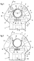
- a press tool 1 is shown, namely its upper head part. It has a tool housing 2 which is hollow on the inside and initially widens towards the bottom and then tapers. In the central area, it has a U-shaped recess 3.
- the free ends of the recess 3 are connected by an abutment bracket 4.
- the abutment bracket 4 is pivotally mounted on its right side in this view about a bearing pin 5. On the left side in this view, the abutment bracket 4 is fixed in the position shown via a locking pin 6. This locking pin 6 passes through corresponding recesses in the tool housing 2 and in the abutment 4 and can be easily removed. After its removal, the abutment bracket 4 can be pivoted about the bearing pin 5 in the directions of the double arrow A, clockwise so far that the recess 3 is completely open towards the top.
- the abutment bracket 4 has a pressing surface 7 which has the shape of a circular arc and extends over an angle of 120 ° symmetrically to the longitudinal axis of the pressing tool 1.
- the pressing surface 7 has a groove which runs in the circumferential direction and is open inwards. It can be exchangeably attached to the abutment bracket 4.
- oblique guide surfaces 8, 9, which enclose an angle of 60 ° and are mirror-symmetrical to the longitudinal axis of the pressing tool 1.
- the pressing jaws 10 ⁇ , 11 are also mirror-symmetrical to the longitudinal axis of the pressing tool 1 and each have a pressing surface 14, 15 which are each designed as circular arc sections extending over 120 °.
- a circumferential groove is also formed on the inside.
- the circular arc sections of all pressing surfaces 7, 14, 15 have identical radii.
- the press jaws 10 ⁇ , 11 protrude on the underside into a guide groove 16 which runs horizontally and transversely to the longitudinal axis of the press tool 1 and is formed in the head 17 of a press ram 18.
- the undersides of the pressing jaws 10 ⁇ , 11 also run horizontally, so that the pressing jaws 10 ⁇ , 11 are guided in the groove 16 so as to be displaceable in the groove 16 transversely to the longitudinal axis of the pressing tool 1, namely in the manner of a dovetail guide.
- transverse blind holes 19, 20 ⁇ are formed, which are coaxial to each other.
- a compression spring 21 is used, which strives to press the pressing jaws 10 ⁇ , 11 outwards and thus over the contact surfaces 12, 13 to the guide surfaces 8, 9.
- the press die 18 is mounted such that it can move linearly vertically in the direction of the longitudinal axis of the press tool 1 (double arrow B). It is operated by a pneumatic or hydraulic working cylinder actuated, which is not shown here.
- the locking of the abutment bracket 4 is first released by means of the locking pin 6, i. H. this locking pin 6 is pulled out and the abutment bracket 4 is pivoted clockwise until the fork-shaped opening of the recess 3 is completely free.
- the press ram 18 is in a downward withdrawn position.
- the pressing tool 1 can then be attached to a coupling sleeve 22 such that the coupling sleeve 22 extends perpendicular to the plane of the drawing through the recess 3 and is received by the latter.
- the abutment 4 is pivoted around the coupling sleeve 22 and locked by inserting the locking pin 6.
- the coupling sleeve 22 is then enclosed by the press tool 1.
- the press jaws 10 ⁇ , 11 are then brought into contact with the coupling sleeve 23 by raising the press ram 18. Since its radius is smaller than the radius of the coupling sleeve 22 before pressing by the intended insertion depth, the pressing surfaces 7, 14, 15 rest only on the circumference of the coupling sleeve 22 with their outer transverse edges. Between the end faces of the pressing jaws 10 ⁇ , 11 and the abutment bracket 4 are still free gaps 23, 24, 25, which are the same size.
- the radii of the circular arc sections of the pressing surfaces 7, 14, 15 start from central points which lie in the tips of an equilateral triangle.
- the press ram 18 is now moved upward by further pressurization.
- the press jaws 10 ⁇ , 11 slide over their contact surfaces 12, 13 over the guide surfaces 8, 9, whereby a direction of movement extending in the directions of the double arrows C, D is impressed on them.
- the two directions of movement include the same angle as the guide surfaces 8, 9, ie 60 °.
- the press jaws 10 ⁇ , 11 slide in the groove 16 of the press ram 18 at the same time horizontally towards each other, against the action of the compression spring 21. In this way, the coupling sleeve 22 is compressed radially, that is, its diameter is reduced by the desired press-in depth.
- a circular press space is enclosed by the press surfaces 7, 14, 15 and the gaps 23, 24, 25 have been reduced to zero.
- the press ram 18 is moved back again.
- the abutment bracket 4 is pivoted away after removing the locking bolt 6, so that the pressing tool 1 can then be removed.
Landscapes
- Mechanical Engineering (AREA)
- Engineering & Computer Science (AREA)
- Press Drives And Press Lines (AREA)
- Automatic Assembly (AREA)
- Perforating, Stamping-Out Or Severing By Means Other Than Cutting (AREA)
- Apparatuses For Bulk Treatment Of Fruits And Vegetables And Apparatuses For Preparing Feeds (AREA)
- Paper (AREA)
- Measurement Of The Respiration, Hearing Ability, Form, And Blood Characteristics Of Living Organisms (AREA)
- Adornments (AREA)
- Infusion, Injection, And Reservoir Apparatuses (AREA)
- Shaping Metal By Deep-Drawing, Or The Like (AREA)
- Earth Drilling (AREA)
- Mounting, Exchange, And Manufacturing Of Dies (AREA)
Applications Claiming Priority (3)
| Application Number | Priority Date | Filing Date | Title |
|---|---|---|---|
| DE4011822 | 1990-04-12 | ||
| DE4011822 | 1990-04-12 | ||
| EP91105662A EP0451806B1 (fr) | 1990-04-12 | 1991-04-10 | Outil de pressage |
Related Parent Applications (2)
| Application Number | Title | Priority Date | Filing Date |
|---|---|---|---|
| EP91105662.0 Division | 1991-04-10 | ||
| EP91105662A Division EP0451806B1 (fr) | 1990-04-12 | 1991-04-10 | Outil de pressage |
Publications (3)
| Publication Number | Publication Date |
|---|---|
| EP0628362A2 true EP0628362A2 (fr) | 1994-12-14 |
| EP0628362A3 EP0628362A3 (fr) | 1995-06-14 |
| EP0628362B1 EP0628362B1 (fr) | 1998-06-17 |
Family
ID=6404263
Family Applications (4)
| Application Number | Title | Priority Date | Filing Date |
|---|---|---|---|
| EP94110655A Expired - Lifetime EP0628362B1 (fr) | 1990-04-12 | 1991-04-10 | Outil de pressage |
| EP91105662A Expired - Lifetime EP0451806B1 (fr) | 1990-04-12 | 1991-04-10 | Outil de pressage |
| EP91105663A Expired - Lifetime EP0452791B1 (fr) | 1990-04-12 | 1991-04-10 | Outil de pressage |
| EP94110654A Expired - Lifetime EP0627273B1 (fr) | 1990-04-12 | 1991-04-10 | Outil de pressage |
Family Applications After (3)
| Application Number | Title | Priority Date | Filing Date |
|---|---|---|---|
| EP91105662A Expired - Lifetime EP0451806B1 (fr) | 1990-04-12 | 1991-04-10 | Outil de pressage |
| EP91105663A Expired - Lifetime EP0452791B1 (fr) | 1990-04-12 | 1991-04-10 | Outil de pressage |
| EP94110654A Expired - Lifetime EP0627273B1 (fr) | 1990-04-12 | 1991-04-10 | Outil de pressage |
Country Status (8)
| Country | Link |
|---|---|
| US (1) | US5148698A (fr) |
| EP (4) | EP0628362B1 (fr) |
| JP (2) | JPH0768329A (fr) |
| AT (4) | ATE116880T1 (fr) |
| CA (2) | CA2040278C (fr) |
| DE (5) | DE9007414U1 (fr) |
| DK (4) | DK0451806T3 (fr) |
| ES (4) | ES2129089T3 (fr) |
Families Citing this family (70)
| Publication number | Priority date | Publication date | Assignee | Title |
|---|---|---|---|---|
| US5598732A (en) * | 1990-04-12 | 1997-02-04 | Dischler; Helmut | Compression tool |
| US6044686A (en) * | 1990-04-12 | 2000-04-04 | Dischler; Helmut | Compression tool for compression molding die |
| DE9103264U1 (de) * | 1991-03-18 | 1991-06-20 | Hewing GmbH, 4434 Ochtrup | Preßzange für das Verpressen von Rohrverbindungen |
| DE4240427C1 (de) * | 1992-12-02 | 1994-01-20 | Novopress Gmbh | Preßwerkzeug |
| DE9216369U1 (de) * | 1992-12-02 | 1993-02-04 | Novopress GmbH Pressen und Presswerkzeuge & Co KG, 4040 Neuss | Preßwerkzeug |
| DE4300934A1 (de) * | 1993-01-15 | 1994-08-18 | Hewing Gmbh | Preßwerkzeug zum Aufpressen eines zylindrischen Preßteils oder eines einen zylindrischen Preßabschnitt aufweisenden Preßteils auf ein Rundprofil |
| WO1994029045A1 (fr) * | 1993-06-03 | 1994-12-22 | Mannesmann Ag | Procede d'installation d'un systeme de canalisations et dispositif de raccordement non liberable |
| DE4318928C1 (de) * | 1993-06-03 | 1994-08-25 | Mannesmann Ag | Verfahren zur Installation eines Leitungsrohrsystems |
| DE19543312C2 (de) * | 1995-11-03 | 1997-10-23 | Rothenberger Werkzeuge Masch | Preßvorrichtung zum radialen Verpressen von Leitungsverbindern |
| EP0771615A1 (fr) | 1995-11-03 | 1997-05-07 | Rothenberger Werkzeuge AG | Appareil de sertissage pour sertissage radial de connexions de tubes |
| EP0858568B1 (fr) * | 1995-11-04 | 2001-12-12 | Novo-Press GmbH Pressen und Presswerkzeuge & Co. Kg. | Procede de raccordement d'un tuyau avec un raccord emmanche a la presse, combinaison de raccord emmanche a la presse, de tuyau et de presse |
| DE29517518U1 (de) * | 1995-11-04 | 1996-05-30 | Novopress GmbH Pressen und Presswerkzeuge & Co KG, 41460 Neuss | Preßwerkzeug |
| DE29602240U1 (de) * | 1996-02-09 | 1997-06-19 | Novopress GmbH Pressen und Presswerkzeuge & Co KG, 41460 Neuss | Preßgerät |
| DE59705051D1 (de) * | 1996-08-17 | 2001-11-29 | Novopress Gmbh | Verfahren zum Verbinden von Werkstücken sowie Pressgerät hierfür |
| DE19637608C1 (de) * | 1996-09-16 | 1997-10-23 | Novopress Gmbh | Verfahren zum Verbinden eines Rohrendes mit einer Rohrkupplung, Verbindung zwischen einer Rohrkupplung und einem Rohrende sowie Rohrkupplung hierfür |
| US6035775A (en) * | 1997-02-21 | 2000-03-14 | Novopres Gmbh Pressen Und Presswerkzeuge & Co. Kg | Pressing device having a control device adapted to control the pressing device in accordance with a servocontrol system of the control device |
| US6240626B1 (en) | 1997-02-21 | 2001-06-05 | Novopress Gmbh Pressen Und Presswerkzauge & Co. Kg | Pressing device |
| DE29703052U1 (de) * | 1997-02-21 | 1997-04-03 | Novopress GmbH Pressen und Presswerkzeuge & Co KG, 41460 Neuss | Preßgerät zum Verbinden von Werkstücken |
| EP0904168A1 (fr) * | 1997-03-11 | 1999-03-31 | Gustav Klauke GmbH | Outil de compression |
| EP0882531A3 (fr) * | 1997-05-28 | 2002-10-16 | Fränkische Rohrwerke Gebr. Kirchner GmbH & Co. | Dispositif d'usinage, en particulier pince à sertir |
| DE19734355C2 (de) * | 1997-08-08 | 2002-08-14 | Uponor Rohrsysteme Gmbh | Preßwerkzeug |
| DE29721759U1 (de) * | 1997-12-10 | 1998-04-09 | Franz Viegener II GmbH & Co. KG, 57439 Attendorn | Preßwerkzeug zum unlösbaren Verbinden eines Fittings und eines eingeführten Metallrohrendes |
| US6217191B1 (en) | 1998-05-29 | 2001-04-17 | Jeng-Shyong Wu | Multiple lamp socket device |
| EP0990490B1 (fr) * | 1998-10-02 | 2001-11-07 | Hans Oetiker AG Maschinen- und Apparatefabrik | Dispositif pour la mise en place, le serrage et le rétrécissement d'un dispositif de maintien annulaire |
| DE19938968A1 (de) | 1999-08-17 | 2001-03-01 | Novopress Gmbh | Handhabbares Arbeitsgerät, insbesondere Preßgerät |
| DE19945113A1 (de) | 1999-09-21 | 2001-03-29 | Novopress Gmbh | Verfahren zur Verbindung eines Preßfittings it einem Rohr sowie Preßfitting, Rohr und Preßgerät zur Durchführung dieses Verfahrens |
| CH693984A5 (de) * | 1999-10-26 | 2004-05-28 | Ridge Tool Ag | Presswerkzeug. |
| DE50006944D1 (de) | 1999-10-26 | 2004-08-05 | Ridge Tool Ag Balzers | Presswerkzeug und Verfahren zum kaltumformenden Verbinden von Werkstücken |
| DE19958103C1 (de) * | 1999-12-02 | 2001-03-01 | Peter Schroeck | Preßwerkzeug zum Verpressen von rotationssymmetrischen Hohlkörpern |
| DE10107579B4 (de) * | 2000-10-19 | 2012-04-26 | Gustav Klauke Gmbh | Presswerkzeug zum Verpressen von Rohrenden sowie Presseinsatz für eine Pressbacke eines Presswerkzeuges |
| DE20018312U1 (de) * | 2000-10-26 | 2001-05-10 | Franz Viegener II GmbH & Co. KG, 57439 Attendorn | Preßwerkzeug |
| DE10106363C1 (de) * | 2001-02-12 | 2002-06-06 | Rothenberger Werkzeuge Ag | Pressenkopf für das Verbinden von Rohrleitungen |
| CN100335193C (zh) * | 2001-09-11 | 2007-09-05 | 美国艾默生电气公司 | 夹紧组件 |
| KR100460205B1 (ko) * | 2002-06-01 | 2004-12-09 | 주식회사 서원기술 | 파이프 압착체결공구 |
| US20030230132A1 (en) * | 2002-06-17 | 2003-12-18 | Emerson Electric Co. | Crimping apparatus |
| US6923037B2 (en) * | 2002-06-17 | 2005-08-02 | Emerson Electric Co. | Assembly for articulating crimp ring and actuator |
| DE10237406A1 (de) * | 2002-08-12 | 2004-03-11 | Mapress Gmbh & Co. Kg | Presswerkzeug |
| US7000448B2 (en) * | 2003-02-12 | 2006-02-21 | Emerson Electric Co. | Compression tool jawarm member |
| DE20309747U1 (de) * | 2003-06-25 | 2003-09-11 | V-Team American Bikes + Products GmbH, 49479 Ibbenbüren | Vorrichtung zum Umformen von rohrförmigem Halbzeug |
| DE202004007032U1 (de) * | 2004-04-30 | 2005-09-15 | Viega Gmbh & Co Kg | Presswerkzeug zum Verpressen von Werkstücken |
| US7188508B2 (en) * | 2004-08-02 | 2007-03-13 | Emerson Electric Co. | Jaw arm for compression tools |
| DE202006004876U1 (de) * | 2006-03-28 | 2007-08-02 | Herrle, Richard | Presswerkzeug, Pressring und Presszange |
| KR100762293B1 (ko) * | 2007-03-30 | 2007-10-01 | 주식회사 다성테크 | 파이프 압착 체결 장치 |
| DE102007047339A1 (de) | 2007-10-04 | 2009-04-09 | Novartec Ag | Presswerkzeug und Presseinrichtung |
| DE202008002200U1 (de) | 2008-02-15 | 2009-03-26 | Novopress Gmbh Pressen Und Presswerkzeuge & Co. Kg | Handgeführtes Pressgerät |
| DE202008006831U1 (de) | 2008-05-20 | 2009-06-25 | Novopress Gmbh Pressen Und Presswerkzeuge & Co. Kg | Handführbares Pressgerät |
| DE102008027812A1 (de) | 2008-06-11 | 2010-01-14 | Novopress Gmbh Pressen Und Presswerkzeuge & Co. Kg | Verfahren zur Verbindung von zwei Werkstücken sowie Pressfitting hierfür |
| JP5528689B2 (ja) * | 2008-09-05 | 2014-06-25 | Ntn株式会社 | 等速自在継手組立方法 |
| DE102009032113B4 (de) | 2009-07-08 | 2011-06-01 | Novopress Gmbh Pressen Und Presswerkzeuge & Co. Kg | Presswerkzeug sowie Verfahren zum Verpressen von insbesondere rohrförmigen Werkstücken |
| DE202009009456U1 (de) | 2009-07-15 | 2010-11-25 | Novopress Gmbh Pressen Und Presswerkzeuge & Co. Kommanditgesellschaft | Presswerkzeug zum Verbinden von insbesondere rohrförmigen Werkstücken |
| CN102054774B (zh) | 2009-10-28 | 2012-11-21 | 无锡华润上华半导体有限公司 | Vdmos晶体管兼容ldmos晶体管及其制作方法 |
| DE102010000545A1 (de) | 2010-02-25 | 2011-08-25 | Joiner's Bench GmbH, 42859 | Hydraulische Pressvorrichtung |
| DE202010000402U1 (de) | 2010-03-18 | 2010-07-01 | Joiner's Bench Gmbh | Pressvorrichtung mit vereinfachtem Aufbau |
| DE202011100316U1 (de) | 2011-05-05 | 2011-07-14 | Novopress Gmbh Pressen Und Presswerkzeuge & Co. Kg | Presswerkzeug sowie verpresstes Pressfitting |
| EP2508275B1 (fr) | 2011-04-04 | 2014-09-10 | Novopress GmbH Pressen und Presswerkzeuge & Co. KG | Outil de pression ainsi que utilisation d'un tel outil de pression |
| DE202011004817U1 (de) | 2011-04-04 | 2011-06-01 | Novopress GmbH Pressen und Presswerkzeuge & Co. KG, 41460 | Presswerkzeug sowie verpresstes Pressfitting |
| DE202011004815U1 (de) | 2011-04-04 | 2011-06-01 | Novopress GmbH Pressen und Presswerkzeuge & Co. KG, 41460 | Presswerkzeug sowie verpresstes Pressfitting |
| DE202011101995U1 (de) | 2011-06-17 | 2012-09-19 | Novopress Gmbh Pressen Und Presswerkzeuge & Co. Kg | Presselement |
| US9388885B2 (en) | 2013-03-15 | 2016-07-12 | Ideal Industries, Inc. | Multi-tool transmission and attachments for rotary tool |
| DE202013007496U1 (de) | 2013-08-21 | 2014-11-28 | Novopress Gmbh Pressen Und Presswerkzeuge & Co. Kg | Pressschlinge zum Verbinden von insbesondere rohrförmigen Werkstücken |
| US10226826B2 (en) | 2013-10-22 | 2019-03-12 | Milwaukee Electric Tool Corporation | Hydraulic power tool |
| DE102014115358A1 (de) * | 2014-10-22 | 2016-04-28 | Michael Schmitz | Presswerkzeug |
| CN205977914U (zh) | 2015-05-06 | 2017-02-22 | 米沃奇电动工具公司 | 液压动力工具 |
| CN105798169B (zh) * | 2016-03-16 | 2018-09-04 | 成都艾亿洋机电有限公司 | 一种卡压钳 |
| CN106583569B (zh) * | 2017-01-23 | 2018-02-23 | 湖南金峰金属构件有限公司 | 一种多单元组合冷挤压机 |
| DE102019217816B4 (de) | 2018-11-29 | 2025-11-13 | Ridge Tool Company | Werkzeugköpfe für scherarbeiten |
| CN112122472A (zh) * | 2020-06-28 | 2020-12-25 | 浙江赛格园林机械有限公司 | 一种缩管机的缩管装置 |
| CN112122471A (zh) * | 2020-06-28 | 2020-12-25 | 浙江赛格园林机械有限公司 | 一种环状击打缩管机 |
| EP4059629A1 (fr) | 2021-03-17 | 2022-09-21 | Viega Technology GmbH & Co. KG | Mâchoire de presse, mâchoire de presse d'entraînement, insert de presse et système pour une compression des raccords avec des tubes |
| DE112022002592T5 (de) | 2021-06-21 | 2024-03-07 | Milwaukee Electric Tool Corporation | Systeme und verfahren zum auswerten von crimpanwendungen |
Family Cites Families (26)
| Publication number | Priority date | Publication date | Assignee | Title |
|---|---|---|---|---|
| US2211008A (en) * | 1940-02-07 | 1940-08-13 | Martin J Goldberg | Hose coupling attaching apparatus |
| US2326709A (en) * | 1941-07-23 | 1943-08-10 | William U Watson | Tool |
| US2381748A (en) * | 1942-11-02 | 1945-08-07 | Chicago Forging & Mfg Co | Method of forming joints |
| DE1198147B (de) * | 1958-07-28 | 1965-08-05 | Aeroquip Ag | Montagewerkzeug zum Einschwenken von Spann-backen einer Schlauchfassung in die Spannstellung |
| US2973024A (en) * | 1958-07-28 | 1961-02-28 | Aeroquip Corp | Assembly tool |
| DE1187870B (de) * | 1958-10-01 | 1965-02-25 | Aga Plaatfoeraedling Aktiebola | Plastisch verformbare metallische Kupplungshuelse zum Verbinden von Metallrohren mit glatten Enden |
| US3220072A (en) * | 1962-04-13 | 1965-11-30 | Doris Moss Oldacre | Clamp structure and assembly tool therefor |
| US3203221A (en) * | 1963-08-26 | 1965-08-31 | Waldes Kohinoor Inc | Plier-type retaining ring assembly tool |
| US3276238A (en) * | 1964-05-18 | 1966-10-04 | Waldes Kohinoor Inc | Plier-like assembly tool |
| FR1426844A (fr) * | 1965-03-30 | 1966-01-28 | Procédé et appareils pour la réalisation de liaisons d'armature | |
| US3575036A (en) * | 1967-09-13 | 1971-04-13 | Amp Inc | Crimping tool and die assembly |
| AU411164B2 (en) * | 1968-02-19 | 1971-02-26 | RUSSELL DUFFIELD and CLAUDE HARCOURT HARVEY FREDERICK | Improved crimping or compression device |
| US3662450A (en) * | 1970-04-24 | 1972-05-16 | Dresser Ind | Hand-portable press for swagable pipe coupling |
| US3688553A (en) * | 1970-06-09 | 1972-09-05 | Henry William Demler Sr | Tube coupling |
| US3695087A (en) * | 1970-08-26 | 1972-10-03 | Arthur H Tuberman | Method and apparatus for pointing tubes |
| DE2136782C2 (de) * | 1971-07-23 | 1982-12-02 | Novopress GmbH Pressen und Presswerkzeuge & Co KG, 4000 Düsseldorf | Tragbares druckmittelbetriebenes Klemmwerkzeug |
| US3756064A (en) * | 1972-03-24 | 1973-09-04 | Waldes Kohinoor Inc | Hand-operated plier-like tools |
| US3823597A (en) * | 1973-07-02 | 1974-07-16 | Mc Donnell Douglas Corp | Swaging tool die extender |
| CH580473A5 (fr) * | 1974-07-08 | 1976-10-15 | Oetiker Hans | |
| US4183120A (en) * | 1978-05-19 | 1980-01-15 | Thorne George W | Encircling devices |
| US4276765A (en) * | 1979-06-14 | 1981-07-07 | Rikizo Yoneda | Pressing device for a hose coupler |
| US4528740A (en) * | 1983-04-18 | 1985-07-16 | Msw Corporation | Shrink ring clamp assembly |
| JPS60141456A (ja) * | 1983-12-28 | 1985-07-26 | Toyoda Gosei Co Ltd | 挟持装置 |
| DE3423283A1 (de) * | 1984-06-23 | 1986-01-02 | Helmut Dipl.-Ing. 4040 Neuss Dischler | Klemmwerkzeug, insbesondere zum verbinden von rohren und anderen profilen |
| DE3513129A1 (de) * | 1985-04-12 | 1986-10-23 | Peter Dipl.-Ing. 6000 Frankfurt Schröck | Radialpresse mit mehreren sternfoermig angeordneten druckmittelantrieben |
| JP5211448B2 (ja) | 2005-08-12 | 2013-06-12 | 住友化学株式会社 | 高分子材料およびそれを用いた素子 |
-
1990
- 1990-04-12 DE DE9007414U patent/DE9007414U1/de not_active Expired - Lifetime
-
1991
- 1991-04-03 US US07/679,943 patent/US5148698A/en not_active Expired - Lifetime
- 1991-04-10 DK DK91105662.0T patent/DK0451806T3/da active
- 1991-04-10 DE DE59104196T patent/DE59104196D1/de not_active Expired - Lifetime
- 1991-04-10 JP JP3077883A patent/JPH0768329A/ja active Pending
- 1991-04-10 EP EP94110655A patent/EP0628362B1/fr not_active Expired - Lifetime
- 1991-04-10 DE DE59109090T patent/DE59109090C5/de not_active Expired - Lifetime
- 1991-04-10 DE DE59102895T patent/DE59102895D1/de not_active Expired - Lifetime
- 1991-04-10 AT AT91105662T patent/ATE116880T1/de not_active IP Right Cessation
- 1991-04-10 EP EP91105662A patent/EP0451806B1/fr not_active Expired - Lifetime
- 1991-04-10 DK DK91105663.8T patent/DK0452791T3/da active
- 1991-04-10 EP EP91105663A patent/EP0452791B1/fr not_active Expired - Lifetime
- 1991-04-10 ES ES94110654T patent/ES2129089T3/es not_active Expired - Lifetime
- 1991-04-10 EP EP94110654A patent/EP0627273B1/fr not_active Expired - Lifetime
- 1991-04-10 JP JP07788491A patent/JP3334892B2/ja not_active Expired - Fee Related
- 1991-04-10 AT AT91105663T patent/ATE111385T1/de not_active IP Right Cessation
- 1991-04-10 ES ES91105662T patent/ES2067077T3/es not_active Expired - Lifetime
- 1991-04-10 DK DK94110655T patent/DK0628362T3/da active
- 1991-04-10 ES ES94110655T patent/ES2119935T3/es not_active Expired - Lifetime
- 1991-04-10 DK DK94110654T patent/DK0627273T3/da active
- 1991-04-10 DE DE59109014T patent/DE59109014D1/de not_active Expired - Lifetime
- 1991-04-10 ES ES91105663T patent/ES2062596T3/es not_active Expired - Lifetime
- 1991-04-10 AT AT94110655T patent/ATE167414T1/de not_active IP Right Cessation
- 1991-04-10 AT AT94110654T patent/ATE175599T1/de not_active IP Right Cessation
- 1991-04-11 CA CA002040278A patent/CA2040278C/fr not_active Expired - Fee Related
- 1991-04-11 CA CA002040277A patent/CA2040277C/fr not_active Expired - Fee Related
Also Published As
Similar Documents
| Publication | Publication Date | Title |
|---|---|---|
| EP0628362B1 (fr) | Outil de pressage | |
| DE3423283C2 (fr) | ||
| EP0671984B1 (fr) | Outil de raccordement par pression | |
| EP0671985B1 (fr) | Outil de pressage | |
| DE3129204C2 (fr) | ||
| EP1591176B1 (fr) | Outil de sertissage de pièces | |
| DE4391315C1 (de) | Vorrichtung zum Aushalsen von Rohren | |
| DE2656210C3 (de) | Bohrstranghalter für Gesteinsbohrgeräte | |
| DE3241746C2 (fr) | ||
| DE3009168A1 (de) | Vorrichtung zum druckpruefen von schlauchleitungen mit metallarmaturen | |
| EP2361701B1 (fr) | Dispositif de presse hydraulique radiale | |
| DE19813854A1 (de) | Vorrichtung zur Herstellung von Quetschverbindungen | |
| DE19511447C2 (de) | Vorrichtung zum Ausformen des Endbereiches eines Rohres für die Verwendung in Schraubverbindungen | |
| DE3413478C2 (de) | Vorrichtung zum Einsetzen eines offenen, mit Montagelöchern in den Endabschnitten versehenen Federrings in eine Umfangsnut einer Bohrung oder Welle | |
| DE3926279C2 (de) | Hydraulisch betriebene Schälvorrichtung zum Einbringen von Mannlöchern in verunglückte Land-, Wasser-, oder Luftfahrzeuge | |
| DE19842765A1 (de) | Vorrichtung zur Herstellung von Quetschverbindungen | |
| DE1752017A1 (de) | Tragbare Presse | |
| EP4640374A1 (fr) | Dispositif de serrage | |
| DE3330658A1 (de) | Vorrichtung zum verbinden von zumindest zwei platten | |
| DE2159885C3 (de) | Vorrichtung zum Aufpressen eines Rohres auf ein Innerhalb des Rohres liegendes Teil | |
| DE20304017U1 (de) | Preßwerkzeug zur Herstellung von Rohrverbindungen | |
| DE20110397U1 (de) | Vorrichtung zum Anschluß eines Rohres oder Schlauches an ein Rohrende | |
| DE68902920T2 (de) | Biegevorrichtung. | |
| DE1104010B (de) | Mechanische Handpresszange zum Verpressen von Verbindungshuelsen und Kabelschuhen mit Draehten, Metallseilen od. dgl. | |
| EP3718695A1 (fr) | Outil de compression pour un raccord à manchon de compression |
Legal Events
| Date | Code | Title | Description |
|---|---|---|---|
| PUAI | Public reference made under article 153(3) epc to a published international application that has entered the european phase |
Free format text: ORIGINAL CODE: 0009012 |
|
| AC | Divisional application: reference to earlier application |
Ref document number: 451806 Country of ref document: EP |
|
| AK | Designated contracting states |
Kind code of ref document: A2 Designated state(s): AT BE CH DE DK ES FR GB IT LI LU NL SE |
|
| PUAL | Search report despatched |
Free format text: ORIGINAL CODE: 0009013 |
|
| AK | Designated contracting states |
Kind code of ref document: A3 Designated state(s): AT BE CH DE DK ES FR GB IT LI LU NL SE |
|
| 17P | Request for examination filed |
Effective date: 19950619 |
|
| 17Q | First examination report despatched |
Effective date: 19960805 |
|
| GRAG | Despatch of communication of intention to grant |
Free format text: ORIGINAL CODE: EPIDOS AGRA |
|
| GRAG | Despatch of communication of intention to grant |
Free format text: ORIGINAL CODE: EPIDOS AGRA |
|
| GRAG | Despatch of communication of intention to grant |
Free format text: ORIGINAL CODE: EPIDOS AGRA |
|
| GRAG | Despatch of communication of intention to grant |
Free format text: ORIGINAL CODE: EPIDOS AGRA |
|
| GRAH | Despatch of communication of intention to grant a patent |
Free format text: ORIGINAL CODE: EPIDOS IGRA |
|
| GRAH | Despatch of communication of intention to grant a patent |
Free format text: ORIGINAL CODE: EPIDOS IGRA |
|
| GRAA | (expected) grant |
Free format text: ORIGINAL CODE: 0009210 |
|
| AC | Divisional application: reference to earlier application |
Ref document number: 451806 Country of ref document: EP |
|
| AK | Designated contracting states |
Kind code of ref document: B1 Designated state(s): AT BE CH DE DK ES FR GB IT LI LU NL SE |
|
| REF | Corresponds to: |
Ref document number: 167414 Country of ref document: AT Date of ref document: 19980715 Kind code of ref document: T |
|
| REG | Reference to a national code |
Ref country code: CH Ref legal event code: EP |
|
| REF | Corresponds to: |
Ref document number: 59109014 Country of ref document: DE Date of ref document: 19980723 |
|
| ET | Fr: translation filed | ||
| GBT | Gb: translation of ep patent filed (gb section 77(6)(a)/1977) |
Effective date: 19980730 |
|
| ITF | It: translation for a ep patent filed | ||
| REG | Reference to a national code |
Ref country code: ES Ref legal event code: FG2A Ref document number: 2119935 Country of ref document: ES Kind code of ref document: T3 |
|
| REG | Reference to a national code |
Ref country code: DK Ref legal event code: T3 |
|
| PLBE | No opposition filed within time limit |
Free format text: ORIGINAL CODE: 0009261 |
|
| STAA | Information on the status of an ep patent application or granted ep patent |
Free format text: STATUS: NO OPPOSITION FILED WITHIN TIME LIMIT |
|
| 26N | No opposition filed | ||
| PGFP | Annual fee paid to national office [announced via postgrant information from national office to epo] |
Ref country code: LU Payment date: 20000421 Year of fee payment: 10 |
|
| PGFP | Annual fee paid to national office [announced via postgrant information from national office to epo] |
Ref country code: DK Payment date: 20000427 Year of fee payment: 10 |
|
| PG25 | Lapsed in a contracting state [announced via postgrant information from national office to epo] |
Ref country code: LU Free format text: LAPSE BECAUSE OF NON-PAYMENT OF DUE FEES Effective date: 20010410 Ref country code: DK Free format text: LAPSE BECAUSE OF NON-PAYMENT OF DUE FEES Effective date: 20010410 |
|
| REG | Reference to a national code |
Ref country code: GB Ref legal event code: IF02 |
|
| PGFP | Annual fee paid to national office [announced via postgrant information from national office to epo] |
Ref country code: GB Payment date: 20020318 Year of fee payment: 12 |
|
| PGFP | Annual fee paid to national office [announced via postgrant information from national office to epo] |
Ref country code: NL Payment date: 20020416 Year of fee payment: 12 |
|
| PGFP | Annual fee paid to national office [announced via postgrant information from national office to epo] |
Ref country code: BE Payment date: 20020419 Year of fee payment: 12 Ref country code: AT Payment date: 20020419 Year of fee payment: 12 |
|
| PGFP | Annual fee paid to national office [announced via postgrant information from national office to epo] |
Ref country code: SE Payment date: 20020422 Year of fee payment: 12 |
|
| PGFP | Annual fee paid to national office [announced via postgrant information from national office to epo] |
Ref country code: ES Payment date: 20020424 Year of fee payment: 12 |
|
| PG25 | Lapsed in a contracting state [announced via postgrant information from national office to epo] |
Ref country code: GB Free format text: LAPSE BECAUSE OF NON-PAYMENT OF DUE FEES Effective date: 20030410 Ref country code: AT Free format text: LAPSE BECAUSE OF NON-PAYMENT OF DUE FEES Effective date: 20030410 |
|
| PG25 | Lapsed in a contracting state [announced via postgrant information from national office to epo] |
Ref country code: SE Free format text: LAPSE BECAUSE OF NON-PAYMENT OF DUE FEES Effective date: 20030411 Ref country code: ES Free format text: LAPSE BECAUSE OF NON-PAYMENT OF DUE FEES Effective date: 20030411 |
|
| PG25 | Lapsed in a contracting state [announced via postgrant information from national office to epo] |
Ref country code: BE Free format text: LAPSE BECAUSE OF NON-PAYMENT OF DUE FEES Effective date: 20030430 |
|
| BERE | Be: lapsed |
Owner name: *DISCHLER HELMUT Effective date: 20030430 |
|
| PG25 | Lapsed in a contracting state [announced via postgrant information from national office to epo] |
Ref country code: NL Free format text: LAPSE BECAUSE OF NON-PAYMENT OF DUE FEES Effective date: 20031101 |
|
| NLV4 | Nl: lapsed or anulled due to non-payment of the annual fee |
Effective date: 20031101 |
|
| EUG | Se: european patent has lapsed | ||
| GBPC | Gb: european patent ceased through non-payment of renewal fee |
Effective date: 20030410 |
|
| REG | Reference to a national code |
Ref country code: ES Ref legal event code: FD2A Effective date: 20030411 |
|
| PGFP | Annual fee paid to national office [announced via postgrant information from national office to epo] |
Ref country code: FR Payment date: 20060420 Year of fee payment: 16 |
|
| PGFP | Annual fee paid to national office [announced via postgrant information from national office to epo] |
Ref country code: IT Payment date: 20060430 Year of fee payment: 16 |
|
| PG25 | Lapsed in a contracting state [announced via postgrant information from national office to epo] |
Ref country code: FR Free format text: LAPSE BECAUSE OF NON-PAYMENT OF DUE FEES Effective date: 20070430 |
|
| PG25 | Lapsed in a contracting state [announced via postgrant information from national office to epo] |
Ref country code: IT Free format text: LAPSE BECAUSE OF NON-PAYMENT OF DUE FEES Effective date: 20070410 |
|
| REG | Reference to a national code |
Ref country code: CH Ref legal event code: NV Representative=s name: ALDO ROEMPLER PATENTANWALT |
|
| PGFP | Annual fee paid to national office [announced via postgrant information from national office to epo] |
Ref country code: CH Payment date: 20100426 Year of fee payment: 20 |
|
| PGFP | Annual fee paid to national office [announced via postgrant information from national office to epo] |
Ref country code: DE Payment date: 20100624 Year of fee payment: 20 |
|
| REG | Reference to a national code |
Ref country code: DE Ref legal event code: R071 Ref document number: 59109014 Country of ref document: DE |
|
| REG | Reference to a national code |
Ref country code: CH Ref legal event code: PL |
|
| PG25 | Lapsed in a contracting state [announced via postgrant information from national office to epo] |
Ref country code: DE Free format text: LAPSE BECAUSE OF EXPIRATION OF PROTECTION Effective date: 20110410 |