EP0600737A2 - Plattenanordnung - Google Patents
Plattenanordnung Download PDFInfo
- Publication number
- EP0600737A2 EP0600737A2 EP93309668A EP93309668A EP0600737A2 EP 0600737 A2 EP0600737 A2 EP 0600737A2 EP 93309668 A EP93309668 A EP 93309668A EP 93309668 A EP93309668 A EP 93309668A EP 0600737 A2 EP0600737 A2 EP 0600737A2
- Authority
- EP
- European Patent Office
- Prior art keywords
- eccentricity
- signal
- clock
- disc
- reproduction
- Prior art date
- Legal status (The legal status is an assumption and is not a legal conclusion. Google has not performed a legal analysis and makes no representation as to the accuracy of the status listed.)
- Granted
Links
- 238000005070 sampling Methods 0.000 claims abstract description 37
- 238000012937 correction Methods 0.000 claims abstract description 21
- 238000001914 filtration Methods 0.000 claims description 8
- 230000006870 function Effects 0.000 claims description 8
- 230000007274 generation of a signal involved in cell-cell signaling Effects 0.000 claims description 5
- 238000012935 Averaging Methods 0.000 claims 7
- 238000006243 chemical reaction Methods 0.000 claims 1
- 238000000034 method Methods 0.000 abstract description 20
- 230000003287 optical effect Effects 0.000 abstract description 4
- 230000033458 reproduction Effects 0.000 description 63
- 238000005259 measurement Methods 0.000 description 53
- 238000010276 construction Methods 0.000 description 25
- 238000000691 measurement method Methods 0.000 description 25
- 238000010586 diagram Methods 0.000 description 15
- 230000003321 amplification Effects 0.000 description 3
- 238000003199 nucleic acid amplification method Methods 0.000 description 3
- 230000002093 peripheral effect Effects 0.000 description 3
- 230000010363 phase shift Effects 0.000 description 3
- 238000013459 approach Methods 0.000 description 2
- 238000013461 design Methods 0.000 description 2
- 239000000284 extract Substances 0.000 description 2
- 238000004519 manufacturing process Methods 0.000 description 2
- 230000010355 oscillation Effects 0.000 description 2
- 238000012545 processing Methods 0.000 description 2
- 230000005428 wave function Effects 0.000 description 2
- NCGICGYLBXGBGN-UHFFFAOYSA-N 3-morpholin-4-yl-1-oxa-3-azonia-2-azanidacyclopent-3-en-5-imine;hydrochloride Chemical compound Cl.[N-]1OC(=N)C=[N+]1N1CCOCC1 NCGICGYLBXGBGN-UHFFFAOYSA-N 0.000 description 1
- 239000003990 capacitor Substances 0.000 description 1
- 238000005520 cutting process Methods 0.000 description 1
- 230000001934 delay Effects 0.000 description 1
- 238000005516 engineering process Methods 0.000 description 1
- 238000002360 preparation method Methods 0.000 description 1
- 230000003252 repetitive effect Effects 0.000 description 1
- 230000001360 synchronised effect Effects 0.000 description 1
Images


Classifications
-
- G—PHYSICS
- G11—INFORMATION STORAGE
- G11B—INFORMATION STORAGE BASED ON RELATIVE MOVEMENT BETWEEN RECORD CARRIER AND TRANSDUCER
- G11B5/00—Recording by magnetisation or demagnetisation of a record carrier; Reproducing by magnetic means; Record carriers therefor
- G11B5/48—Disposition or mounting of heads or head supports relative to record carriers ; arrangements of heads, e.g. for scanning the record carrier to increase the relative speed
- G11B5/4806—Disposition or mounting of heads or head supports relative to record carriers ; arrangements of heads, e.g. for scanning the record carrier to increase the relative speed specially adapted for disk drive assemblies, e.g. assembly prior to operation, hard or flexible disk drives
- G11B5/4826—Mounting, aligning or attachment of the transducer head relative to the arm assembly, e.g. slider holding members, gimbals, adhesive
-
- G—PHYSICS
- G11—INFORMATION STORAGE
- G11B—INFORMATION STORAGE BASED ON RELATIVE MOVEMENT BETWEEN RECORD CARRIER AND TRANSDUCER
- G11B21/00—Head arrangements not specific to the method of recording or reproducing
- G11B21/02—Driving or moving of heads
- G11B21/10—Track finding or aligning by moving the head ; Provisions for maintaining alignment of the head relative to the track during transducing operation, i.e. track following
- G11B21/106—Track finding or aligning by moving the head ; Provisions for maintaining alignment of the head relative to the track during transducing operation, i.e. track following on disks
-
- G—PHYSICS
- G11—INFORMATION STORAGE
- G11B—INFORMATION STORAGE BASED ON RELATIVE MOVEMENT BETWEEN RECORD CARRIER AND TRANSDUCER
- G11B7/00—Recording or reproducing by optical means, e.g. recording using a thermal beam of optical radiation by modifying optical properties or the physical structure, reproducing using an optical beam at lower power by sensing optical properties; Record carriers therefor
- G11B7/08—Disposition or mounting of heads or light sources relatively to record carriers
- G11B7/09—Disposition or mounting of heads or light sources relatively to record carriers with provision for moving the light beam or focus plane for the purpose of maintaining alignment of the light beam relative to the record carrier during transducing operation, e.g. to compensate for surface irregularities of the latter or for track following
- G11B7/095—Disposition or mounting of heads or light sources relatively to record carriers with provision for moving the light beam or focus plane for the purpose of maintaining alignment of the light beam relative to the record carrier during transducing operation, e.g. to compensate for surface irregularities of the latter or for track following specially adapted for discs, e.g. for compensation of eccentricity or wobble
- G11B7/0953—Disposition or mounting of heads or light sources relatively to record carriers with provision for moving the light beam or focus plane for the purpose of maintaining alignment of the light beam relative to the record carrier during transducing operation, e.g. to compensate for surface irregularities of the latter or for track following specially adapted for discs, e.g. for compensation of eccentricity or wobble to compensate for eccentricity of the disc or disc tracks
Definitions
- the present invention relates to a disk unit such as a magnetic disk unit or an optical disk unit and more particularly to a clock signal correcting circuit suitable for a so-called "sampled servo system" disk unit in which a plurality of clock marks which provide a timing standard are embedded in data tracks on the surface of the disks beforehand, for example at the time of manufacture.
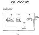
- the clock generating circuit shown in Fig. 1 is a so-called PLL (Phase Locked Loop) circuit.
- the PLL circuit 130 comprises a phase comparator 131, a loop filter 132, a VCO (voltage controlled oscillator) 135 and a frequency divider 136.
- a clock signal reproduced from a disk is supplied to one of the inputs of the phase comparator 131.
- a clock signal output from the VCO 135 whose frequency is divided by N by the frequency divider 136 is supplied to the other input of the phase comparator 131.
- the loop filter 132 performs a prescribed filtering process such as lowpass filtering on the output of the phase comparator 131 and supplies its output to the VCO 135.
- the VCO 135 outputs a clock signal that corresponds to the input voltage.
- the resulting clock signal output from the VCO 135 is locked to the phase of the reproduced signal from the disk.
- the clock generating circuit described above has the following problems in generating accurate clock signals.
- a disc device for use with a disc having data tracks provided in advance with a plurality of clock marks for providing a timing standard, the device having reproduction means, including a reproduction head, for reproducing information recorded on the disc; clock sampling means, for extracting a first clock signal outputted by the reproduction means; eccentricity magnitude memory means, for storing a signal corresponding to the eccentricity of the data tracks with respect to the axis of rotation of the disc; and clock correction means, including voltage control oscillator means, for, according to the signal corresponding to the eccentricity, causing a second clock signal outputted by the voltage control oscillator means to follow the first clock signal by changing the phase of the second clock signal or the frequency of the second clock signal.
- the disc device may also be provided with home index sampling means, for sampling a home index signal indicating the rotational phase origin of the disc from the output of the reproduction means, and the signal corresponding to the eccentricity is a signal in which the phase difference between the clock at prescribed angular positions on the disc and the first clock is expressed as a function and which has the home index signal generation position as a reference origin.
- the clock correction means may comprise: phase comparison means, for comparing the phase of the first clock signal with the phase of the second clock signal; filtering means, for performing prescribed filtering on the output of the phase comparison means; and adding means, for, in synchrony with the disc rotation, adding the output of the filter means to the signal corresponding to the eccentricity and supplying the resulting signal to the voltage control oscillator means.
- the disc device may also comprise: eccentricity magnitude measuring means, for measuring the signal corresponding to the eccentricity from the first clock signal and the output signal of the reproduction means and supplying it to the eccentricity magnitude memory means.
- This eccentricity magnitude measuring means may use a method such as measuring the signal corresponding to the eccentricity by calculating the number of tracks which the reproduction head crosses or obtaining the signal corresponding to the eccentricity from the non-uniformity of spacing observed in a string of originally uniformly spaced clock pulses reproduced from the disc.
- the device may comprise reproduction means, including a reproduction head, for reproducing information recorded on the discs; track number sampling means, for sampling the track numbers of the disc from the output of the reproduction means; clock sampling means, for extracting a first clock signal from the output of the reproduction means; eccentricity magnitude measuring means, for measuring a signal corresponding to the eccentricity of the data tracks of each disc with respect to the axis of rotation of the disc from the first clock signal and the output signal of the reproduction means; eccentricity magnitude memory means, for storing the signal corresponding to the eccentricity; eccentricity magnitude adjusting means, for changing the signal corresponding to the eccentricity stored in the eccentricity magnitude memory means according to the sampled track number; clock correction means, including a voltage controlled oscillator means, for, according to the signal corresponding to the eccentricity changed by the eccentricity adjusting means, causing a second clock signal outputted by the voltage controlled oscill
- home index sampling means for sampling a home index signal indicating the rotational phase origin of the disc from the output of the reproduction means.
- the signal corresponding to the eccentricity may be a signal in which the phase difference between the clock at prescribed angular positions in the disc and the first clock is expressed as a function and which has the home index signal generation position as its reference origin.
- the eccentricity magnitude adjusting means may comprise: adjustment coefficient memory means, for storing, in correspondence with the sampled track numbers, the amplitudes of the time intervals of the clock mark reproduction signals as adjustment coefficients for use in adjusting the signal corresponding to the eccentricity; and multiplying means, for multiplying the signal corresponding to the eccentricity stored in the eccentricity magnitude memory means by the adjustment coefficients stored in the adjustment coefficient memory means.
- the disc device may further comprise: phase difference memory means, for storing, in correspondence with the sampled track numbers, the phase difference between the home index of the axis of rotation of the disc and the home index on the data tracks, and for outputting the phase differences according to inputted track numbers; and readout means, for, according to the phase difference outputted by the phase difference memory means, reading out signals corresponding to the eccentricity and supplying them to the multiplying means.
- phase difference memory means for storing, in correspondence with the sampled track numbers, the phase difference between the home index of the axis of rotation of the disc and the home index on the data tracks, and for outputting the phase differences according to inputted track numbers
- readout means for, according to the phase difference outputted by the phase difference memory means, reading out signals corresponding to the eccentricity and supplying them to the multiplying means.
- this invention may provide a disc device which can correctly follow up the eccentricity of the disk.
- it may provide a disc device which can immediately follow up the eccentricity of the disk face to be accessed when it is changed among a plurality of disk faces.
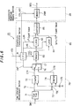
- Fig. 2 is a block diagram showing the structure of a first embodiment in which the present invention is applied to a magnetic hard disk unit.
- Double-sided magnetic disks 1A, 1B, 1C and 1D are rotated and driven by a spindle motor 2.
- Magnetic heads 3A, 3B, 3C and 3D are supported by arms 4A, 4B 4C and 4D and are turned about the turning center 5C by a voice coil motor (VCM) 5 to follow up tracks 502 on the upper sides of the double-sided magnetic disks 1A, 1B, 1C and 1D and to write/read data to/from those tracks.
- VCM voice coil motor
- the tracks 502 of those four magnetic disks lA, 1B, 1C and 1D form a cylinder 100.
- four magnetic heads for writing/reading data to/from the back sides of the double sided magnetic disks 1A, 1B, 1C and 1D are provided and are supported by the arms 4A, 4B, 4C and 4D in the same way as the magnetic heads 3A, 3B, 3C and 3D and are turned about the turning center 5C by the VCM 5.
- a plurality of clock marks for providing a timing standard are embedded in the data tracks on the surface of the magnetic disks 1A, 1B, 1C and 1D beforehand when the disks are manufactured.
- the reference numeral (6) denotes the center of rotation of the spindle motor 6, i.e. the center of rotation of the magnetic disks 1A, 1B, 1C and 1D.
- a host computer 50 supplies commands such as write and read commands to a controller 70 via an interface cable 60.
- the controller 70 outputs control signals for controlling the magnetic hard disk unit to a signal processing circuit 20.
- Reproduced signals read out from the magnetic disks 1A, 1B, 1C and 1D by the magnetic heads 3A, 3B, 3C and 3D are amplified to a predetermined amplitude by a reproduction and amplification circuit 21.
- the output of the reproduction and amplification circuit 21 is fed to a clock sampling circuit 22, a track position error detecting circuit 23, and a home index (one pulse per 1 revolution) sampling circuit 24.
- the reproduced clock signal sampled by the clock sampling circuit 22 is supplied to a track eccentricity magnitude measurement section 25.
- a track position error signal output from the track position error detecting circuit 23 is also supplied to the track eccentricity magnitude measurement section 25.
- a home index signal sampled by the home index sampling circuit 24, i.e. a rotational phase origin signal is also supplied to the track eccentricity magnitude measurement section 25.
- the track eccentricity magnitude measurement section 25 measures the eccentricity magnitude of the data track circle 502 from the center of the axis of rotation 6 as a function of angular position ⁇ on the disk, where a home index generating position is set at zero degrees of angular coordinate value by a known method or by a method of the present invention described later, and stores it in an eccentricity magnitude memory section 26 in table form.
- a tracking servo circuit 40 utilizes this eccentricity magnitude for controlling the VCM 5. As explained above, this eccentricity magnitude is a different quantity from the 'eccentricity' mentioned above.
- 'eccentricity magnitude' refers to the phase shift that originates in the eccentricity introduced during disc chucking, and, more specifically, refers to a signal which expresses as a function the phase difference between the clock at predetermined angular positions in the disc, having the home index signal generation position as the reference origin, and the first clock.
- 'Eccentricity Magnitude' is used with this meaning hereinafter throughout the description of the preferred embodiments.
- the eccentricity magnitude stored in the memory section 26 is additionally applied in a feed forward manner as the control voltage of a voltage controlled oscillator (VCO) 35 in a PLL circuit 30 after being read out in synchronization with the rotation of the disk by a read circuit 27, being converted into an analog signal by a D/A converter 28 and being compensated or converted into a velocity signal by a feed forward compensator 29.
- VCO voltage controlled oscillator
- the PLL circuit 30 comprises a phase comparator 31, a loop filter 32 for performing a prescribed filtering process such as lowpass filtering on the output of the phase comparator 31, and the VCO 35 for outputting a clock signal having a phase or frequency that corresponds to the output of the loop filter 32.
- the phase comparator 31 outputs the phase difference between the clock signal sampled by the clock sampling circuit 22 and the clock signal fed back from the VCO 35 via a 1/N frequency divider 36.
- the present embodiment shown in Fig. 2 is characterized in that an analog adder (operational amplifier) 33 is provided between the loop filter 32 and the VCO 35 and that a signal supplied from the feed forward compensator 29 via a switch 34 is added to the signal output from the loop filter 32 and is supplied to the VCO 35.
- the loop filter 32 and adder 33 may be a digital computing element.
- the VCO 35 is driven not only by the output from the phase comparator 31 but also by a track circle eccentricity indicating voltage arriving from the eccentricity magnitude memory section 26 via the read circuit 27, the D/A converter 28, the feed forward compensator 29 and the switch 34. Accordingly, the VCO 35 follows up pulse signals of 840 pulses per revolution generated from the disk by the so-called closed loop operation and also performs an open loop operation with a present instantaneous eccentricity magnitude predicting signal from the memory section 26.
- the clock from the disk observed from the reproduction head fixed in the ⁇ direction has a fluctuation compressed in the direction of the time axis.
- the clock signal output from the clock sampling circuit 22 and the clock signal output from the VCO 35 are caused to approach the same phase of about ⁇ 20 ns (nano-seconds).
- the closed loop operation only needs to eliminate mostly the high frequency components (several times to several tens of times of the rotational frequency) whose amplitudes are smaller among the fluctuation components.
- the output signal of the VCO 35 can be maintained finally in a very close oscillation phase of less than ⁇ 1 ns from the clock signal output from the clock sampling circuit 22.
- the original disk is manufactured by a cutting machine having a feed precision of around 0.01 micron, similar to that of an optical disk manufacturing machine, its roundness is sufficiently better than 1 micron.
- This first method is the most direct method. That is, the magnetic disks 1A, 1B, 1C and 1D are rotated after restricting the magnetic heads 3A, 3B, 3C and 3D both in the R and ⁇ directions. It will now be supposed that a disk whose track width is 10.0 ⁇ m and eccentricity is 50 ⁇ m is nounted. Seeing from the side of the reading head, a phenomenon is observed that about 5 tracks escape to the peripheral side and then return to the inner side as the disk rotates. Accordingly, an approximate eccentricity magnitude can be found by counting the number of tracks crossed.
- a track lumber is given to every track from the inner periphery to the outer periphery, and the marks are marked with an adequate repetitive frequency across one circuit of all the tracks beforehand when the disk is fabricated.
- the number of the marks is 840/circuit.
- a virtual closed loop servo is activated so that only the same track number is followed up by track number reading means (not shown) and the tracking servo circuit 40.
- track number reading means not shown
- this third eccentricity magnitude measuring method finds the eccentricity magnitude from unequal intervals observed in a clock pulse train reproduced from one track which has originally equal intervals and stores the result in the memory section 26.
- the reference numeral (500) indicates the center of the track 502 and (501) indicates the center of rotation of the disk.
- the reproducion head 3 is supported by the arm 4 and is positioned by the tracking servo circuit 40 so that it traces along the center of the track 502.
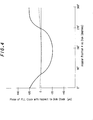
- the switch 34 in Fig.2 is kept in the open state to operate the PLL circuit 30 only in a closed loop and the output from the VCO 35 at this time is taken as a time standard. Based on this time standard, the phase of the reproduced clock from the clock sampling circuit 22 is measured across one circuit. At this time, 840 time data are observed as shown in Fig. 4. 3ecause the time standard used at this time is the output of the PLL circuit 30 following up in the closed loop and the time standard itself also is following up the eccentricity by Loop gain, the observed result is already suppressing the eccentricity to some extent.
- the shift of the phase from the true time axis caused by the eccentricity is the observed result multiplied by the loop gain (normally a constant less than 100). Since the observed value is ⁇ 18 ns, and the loop gain at 60 Hz is 40 times, one point on the disk is causing a delay of advancement of ⁇ 720 ns from the constant velocity time axis.
- the preparation of the eccentricity table is completed by storing the delays of advancement observed in one revolution in the memory section 26 as digital numerical values.
- the content of the memory section 26 is read out by the read circuit 27 in synchronization with the rotational phase of the disk and is converted into an analog voltage by he D/A converter 28. Then after being phase compensated through the feed forward compensator 29 composed of a coil L, capacitor C and resistor R, it is applied to the VCO 35 via the switch 34 and the analog adder 33. As a result, the oscillation phase of the VCO 35 approaches almost to zero degrees across the whole range of one rotation, as shown by the broken line in Fig. 4.
- Fig. 5 illustrates the relationship between a magnetic disc on which N clock mark signals, physically spaced at uniform intervals, are recorded on each of the circular data tracks, and the locus described by a recording and reproduction head, i.e. a signal readout head, when the head is positioned at a fixed radius from the center of rotation of the chucked disc.
- reference numeral 500 denotes the center of the circular data tracks; data tracks 3 through 7 lie in concentric circles about this center 500, and N clock mark signals CM are recorded on each of the data tracks, physically spaced at uniform intervals around the disc.
- Reference numeral 503 denotes the circular locus described by a recording and playback head, i.e. a signal readout head, when the head is positioned at a fixed radius 510 from the center of rotation 501 of the chucked disc.
- the head travels the distance 513 between the clock mark signals CM in the circular data track through which the circular locus 503 passes when the head is closest to the center 500 of the data tracks in the shortest time, and takes the longest time to travel the distance 514 between the clock marks in the circular data track through which the circular locus 503 passes when the head is farthest from the center 500 of the data tracks. This is because the disc rotation radius 510 and the head speed are constant.
- the eccentricity magnitude of the disc, caused by the eccentricity 511, for any angular position of the disc can be obtained.
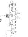
- Fig. 6 illustrates a construction for practicing the fourth eccentricity measurement method of this invention.
- a time interval measurement section 70 uses the home index signal HIS to measure the time intervals between clock mark reproduction signals CMS outputted by a clock sampling circuit 22.
- An eccentricity magnitude computing section 80 uses the home index signal HIS to calculate the eccentricity magnitude with angular position of the disc 1 from the time intervals between the clock mark reproduction signals CMS.
- the CPU 81 is also provided with memory access functions.
- a control signal CS1 and an address signal AS1 are outputted by the CPU 81 based on the home index signal HIS.
- An eccentricity magnitude memory section 26 stores eccentricity magnitudes outputted by the eccentricity magnitude computing section 80 according to the control signal CS1 and the address signal AS1.
- the eccentricity magnitudes stored in the eccentricity memory section 26 are read out in accordance with the control signal CS1 and the address signal AS1 outputted by the CPU 81 based on the home index signal HIS.
- the eccentricity magnitudes read out from the eccentricity memory 26 give the eccentricity distances of the circular data tracks of the disc 1 from the head locus 503 (see Fig. 5).
- the time interval measurement section 70 includes a flip-flop 71, a counter 72, an invertor 73, a counter 74, an oscillator 75, and a switch 76.
- the eccentricity magnitude computing section 80 includes the CPU 81, a memory 82, latches 83 and 84, and a subtracter 85.
- the eccentricity magnitude memory section 26 includes a memory 26M.
- the flip-flop 71 outputs a pulse signal TD which changes between High and Low at the TTL level.
- This pulse signal TD is supplied directly to the counter 72 and is also supplied to the counter 74 after being reversed by the invertor 73.
- the counter 72 uses the oscillator 75 to measure the time intervals during which the pulse signal TD is High, and outputs time interval measured values CTA.
- the counter 74 uses the oscillator 75 to measure the time intervals during which the pulse signal from the invertor 73 is High, i.e. the time intervals during which the pulse signal TD is Low, and outputs time interval measured values CTB.
- the switch 76 outputs the time interval measured values CTA outputted by the counter 72 and the time interval measured values CTB outputted by the counter 74 alternately as count values CT, according to a control signal CNT outputted by the CPU 81 based on the home index signal HIS.
- the memory 82 stores in order (N+N/2) time interval measured values CT supplied from the switch 76, according to a control signal CS2 and an address signal AS2 outputted by the CPU 81 based on the home index signal HIS.
- the time interval measured values stored in the memory 82 are read out according to the control signal CS2 and the address signal AS2 outputted by the CPU 81.
- the p th time interval measured value read out is held in the latch 83 according to a latch signal LHA outputted by the CPU 81.
- the (p+N/2) th time interval measured value read out is held in the latch 84 according to a latch signal LHB outputted by the CPU 81.
- the subtracter 85 subtracts the (p+N/2) th time interval measured value from the p th time interval measured value.
- the N results thus obtained by the subtracter 85 are stored in order in the memory 26M according to the control signal CS1 and the address signal AS1 outputted by the CPU 81 based on the home index signal HIS.
- the subtraction results stored in the memory 26M represent the eccentricity magnitude with angular position of the disc, and give the distance, due to eccentricity, of the circular data tracks from the head locus 503 (see Fig. 5); they are read out as eccentricity magnitudes OSS according to the control signal CS1 and the address signal AS1 outputted by the CPU 81 based on the home index signal HIS, and can be used as an eccentricity distance table for performing eccentricity correction.
- Fig. 7 shows the relationship between the clock mark reproduction signals CMS and the measured time intervals in the example construction shown in Fig. 6.
- the count value of the time interval between the n th clock mark reproduction signal CMS and the (n+1) th clock mark reproduction signal CMS expressed as t(n)
- the count value for when the locus 503 of Fig. 5 is farthest from the circular data track center 500 is written as t(k)
- the count value for when the locus 503 is closest to the data track center 500 is t(k+N/2).
- Fig. 8 shows an example of a clock mark reproduction signal time interval measured by a time interval measuring section 70 constructed as shown in Fig. 6, i.e. the string of count values CT stored in the memory 82 plotted against their data numbers.
- the count value for when the locus 503 of Fig. 5 is farthest from the circular data track center 500 is t(k)
- the count value for when the locus 503 is closest to the data track center 500 is t(k+N/2).
- Fig. 9 shows an example of the eccentricity magnitude stored in association with the disc angle in the memory 26M of an eccentricity magnitude memory section constructed as shown in Fig. 6, i.e. the eccentricity measurement results showing the distance, due to eccentricity, of the circular data tracks from the head locus 503 (see Fig. 5), obtained by subtracting the (p+N/2) th time interval measured value from the p th time interval measured value as described above.
- the data string OSS stored in the memory 26M can be used as a table of eccentricity distance with disc angular position for eccentricity correction.
- Fig. 10 illustrates a construction for practicing a fifth eccentricity magnitude measurement method of this invention.
- the time interval measured values measured by the time interval measuring section 70A are stored in order in a memory 82A according to a control signal CS3 and an address signal AS3 outputted by a memory access section 81A based on the home index signal HIS.
- the time interval measured values stored in the memory 82A are read out according to the control signal CS3 and the address signal AS3 outputted by the memory access section 81A based on the home index signal HIS.
- the subtraction results obtained by the subtracter 85A are stored in order in a memory 86A according to a control signal CS4 and an address signal AS4 outputted by the memory access section 81A based on the home index signal HIS.
- the subtraction results obtained by the subtracter 85A are also summed in an adder 87A into sums of the values of N results, and a divider 88A divides the summing results obtained by the adder 87A by N and outputs average values AV1.
- the subtraction results stored in the memory 86A are read out in order according to the control signal CS4 and the address signal AS4 outputted by the memory access section 81A based on the home index signal HIS.
- the subtraction results obtained by the subtracter 89A are stored in order in a memory 26MA according to a control signal CS5 and an address signal ASS outputted by the memory access section 81A based on the home index signal HIS.
- the subtraction results stored in the memory 26MA represent the eccentricity magnitude with angular position of the disc, and give the distance, due to eccentricity, of the circular data tracks from the head locus 503 (see Fig. 5); they are read out as eccentricity magnitudes OSSA according to the control signal CS5 and the address signal ASS outputted by the memory access section 81A based on the home index signal HIS, and can be used as an eccentricity distance table for performing eccentricity correction.
- noise can be reduced further than is possible with the method shown in Fig. 6.
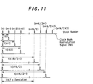
- Fig. 11 shows the relationship between the clock mark reproduction signals and the measured time intervals obtained in the measurement method shown in Fig. 10.
- the time interval between the n th clock mark replay signal CMS and the (n+m) th clock mark reproduction signal CMS is t(n+m-1).
- Fig. 12 shows the clock mark reproduction signal time interval 290 measured by the time interval measurement section 70A and stored in the memory 82A, the time interval measured value 291 subtracted by the subtracter 85A, and the average value AV1 outputted by the divider 88A, plotted against clock number, for the measurement method illustrated in Fig. 10.
- Fig. 13 shows an example of the eccentricity magnitude stored in association with the disc angle in the memory 26MA of Fig. 10, i.e. the distance, due to eccentricity, of the circular data tracks from the head locus 503 (see Fig. 5); this data string OSSA stored in the memory 26MA can be used as a table of eccentricity distance with disc angular position for eccentricity correction.
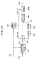
- Fig. 14 illustrates a construction for practicing a sixth eccentricity measurement method of this invention.
- the time interval measured values measured by the time interval measurement section 70B are stored in order in a memory 82B according to a control signal CS6 and an address signal AS6 outputted by a memory access section 81B based on the home index signal HIS.
- the time interval measured values stored in the memory 82B are read out according to the control signal CS6 and the address signal AS6 outputted by the memory access section 81B based on the home index signal HIS.
- the time interval measured values read out from the memory 82B are summed in an adder 87B into sums of N consecutive values, and a divider 88B divides the summation results obtained by the adder 87B by N and outputs average values AV2.
- the subtraction results obtained by the subtracter 89B are stored in order in a memory 26MB according to a control signal CS7 and an address signal AS7 outputted by the memory access section 81B based on the home index signal HIS.
- the subtraction results stored in the memory 26MB represent the eccentricity magnitude with angular position of the disc, and give the distance, due to eccentricity, of the circular data tracks from the head locus 503 (see Fig. 5); they are read out as eccentricity magnitudes OSSB according to the control signal CS7 and the address signal AS7 outputted by the memory access section 81B based on the home index signal HIS, and can be used as an eccentricity distance table for performing eccentricity correction.
- the measurement method shown in Fig. 14 the number of counters for time interval measurement can be reduced further than is possible with the method shown in Fig. 10.
- Fig. 15 shows the relationship between the clock mark reproduction signals and the measured time intervals in the sixth measurement method illustrated in Fig. 14.
- the time interval between the n th clock mark reproduction signal CMS and the (n+N/2) th clock mark reproduction signal CMS is t(n).
- Fig. 16 shows the clock mark reproduction signal time interval measured value CTB, measured by the time interval measurement section 70B and stored in the memory 82B, and the average value AV2 outputted by the divider 88B, plotted against data number, for the measurement method illustrated in Fig. 14.
- Fig. 17 shows an example of an eccentricity magnitude/disc angle curve OSSB stored in the memory 26MB of the sixth measurement method illustrated in Fig. 14, i.e. the distance, due to eccentricity, of the circular data tracks from the head locus 503 (see Fig. 5); this data string OSSB stored in the memory 26MB can be used as a table of eccentricity distance against disc angular position for eccentricity correction.
- Fig. 18 illustrates a construction for practicing a seventh eccentricity magnitude measurement method.
- the time interval measured values measured by the time interval measurement section 70C are stored in order in a memory 82C according to a control signal CS8 and an address signal AS8 outputted by a memory access section 81C based on the home index signal HIS.
- the time interval measured values stored in the memory 82C are read out according to the control signal CS8 and the address signal AS8 outputted by the memory access section 81C based on the home index signal HIS.
- the summation results obtained by the adder 85C are stored in a memory 86C according to a control signal CS9 and an address signal AS9 outputted by the memory access section 81C based on the home index signal HIS.
- the summation results obtained by the adder 85C are also summed in an adder 87C into sums of the values of N results, and a divider 88C divides the summation results obtained by the adder 87C by N and outputs average values AV3.
- the summation results stored in the memory 86C are read out in order according to the control signal CS9 and the address signal AS9 outputted by the memory access section 81C based on the home index signal HIS.
- the subtraction results obtained by the subtracter 89C are stored in order in a memory 26MC according to a control signal CS10 and an address signal AS10 outputted by the memory access section 81C based on the home index signal HIS.
- the subtraction results stored in the memory 26MC represent the eccentricity magnitude with angular position of the disc, and give the distance, due to eccentricity, of the circular data tracks from the head locus 503 (see Fig. 5); they are read out as eccentricity magnitudes OSSC according to the control signal CS10 and the address signal AS10 outputted by the memory access section 81C based on the home index signal HIS, and can be used as an eccentricity distance table for performing eccentricity correction.
- noise can be reduced further than is possible with the method shown in Fig. 6, and the number of counters for time interval measurement can be reduced further than is possible with the method shown in Fig. 14.
- Fig. 19 shows the relationship between the clock mark reproduction signals and the measured time intervals CTC in the seventh measurement method illustrated in Fig. 18.
- the time interval between the n th clock mark reproduction signal CMS and the (n+1) th clock mark reproduction signal CMS is t(n).
- Fig. 20 shows the clock mark replay signal time interval measured value CTC, measured by the time interval measurement section 70C and stored in the memory 82C, and the average value AV3 outputted by the divider 88C, in the measurement method illustrated in Fig. 18.
- the time interval measurement section 70C measures in the smallest time units of the measuring means. When the smallest time units are coarse with respect to the eccentricity magnitude, the measured time interval data string CTC is stepped with respect to the angular position of the disc. If the number N/2 of time interval data string CTC values measured in step form summed in the adder 85C is sufficiently large, the eccentricity information obtained can be smoothly reproduced with respect to the angular position of the disc.
- Fig. 21 shows an example of an eccentricity magnitude/disc angle curve OSSC stored in the memory 26MC of the measurement method illustrated in Fig. 18, i.e. the distance, due to eccentricity, of the circular data tracks from the head locus 503 (see Fig. 5); this data string OSSC stored in the memory 26MC can be used as a table of eccentricity distance with disc angular position for eccentricity correction.
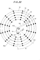
- Fig. 22 shows N clock marks recorded at physically uniform intervals around each of the circular data tracks in a magnetic disc, and shows the change in the radius of the recording and reproduction head, i.e. the signal readout head, as it runs around one track, due to eccentricity between the center of the circular data tracks and the center of rotation of the spindle.
- features which are the same as features shown in Fig. 5 have been given the same reference numbers as they have in Fig. 5.
- the eccentricity distance 511 between the center 500 of the data tracks and the rotating shaft 501 of the spindle motor will be written d
- the radial distance 512 from the center 500 of the data tracks will be written r
- the angle between the straight line connecting the head traveling position HP to the center 500 of the data tracks and the straight line connecting the center 500 of the data tracks and the center of rotation 501 of the spindle will be written ⁇
- the angular velocity of the spindle will be written ⁇ .
- the number N of clock marks per circular data track and the angular velocity ⁇ of the spindle are design values and are therefore known. Therefore, for any desired head traveling radius r, using the two values the eccentricity distance d and the clock number N1 from the home index signal HIS recorded in the tracks to the greatest value of the time taken by the head to travel between clock marks, the eccentricity correction magnitudes all the way round the disc can be obtained from Equation 9.
- Fig. 23 shows a construction for practicing an eighth eccentricity magnitude measurement method in which the eccentricity magnitude along the time axis is measured.
- a time interval measuring section 70D measures the time intervals between the clock mark reproduction signals CMS reproduced from the disc, and outputs time interval measured values CTD.
- a counter 301 uses a home index signal HIS to count the number of clock mark reproduction signals CMS and outputs the count value n.
- a comparator 302 extracts the maximum value t14 from the time interval measured values CTD and holds it in a maximum value memory 303, and also extracts the minimum value t13 and holds it in a minimum value memory 304.
- the comparator 302 also stores the count value N1 for the time at which the maximum value t14 was sampled in a memory 306.
- a computing device 305 uses the maximum value t14 stored in the memory 303, the minimum value t13 stored in the memory 304, the predetermined number of clock marks N and disc angular velocity , and the head traveling radius R, and performs the computation of Equation 13, and stores the computed result for the eccentricity distance d in the memory 306.
- a computing device 307 uses the count value N1 for the time at which the maximum value t14 was sampled, i.e. the count value indicating the phase difference from the home index signal, stored in the memory 306, and the eccentricity distance d, and the count value n of the clock marks from the home index signal, and performs the computation of Equation 9.
- the computation results for one circuit of the disc outputted by the computing device 307 can be used as eccentricity correction magnitudes with disc angular position.
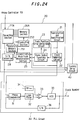
- Fig. 24 shows a second preferred embodiment of the disc device of the present invention.
- the dislocation (eccentricity magnitude) of the track itself for each position in the rotation of the disk is used as the content stored in the memory section 26,
- the dislocation of the track itself is stored temporarily in a temporary memory section 251 and then a value obtained by a computation equivalent to that carried out by the feed forward compensator 29 in Fig. 2 is performed on it by the computing section 252 and the resulting magnitude is stored in the memory section 26A.
- the value stored in the memory section 26A is a velocity corresponding to the eccentricity.
- This arrangement has the merit that the feed forward compensator 29 in Fig. 2 can be omitted. That is, although the feed forward compensator 29 in Fig. 2, i.e. the filter, needs to be constructed using high speed devices to carry out a real-time operation, since the measurement of eccentricity is carried out about once a day, a low cost general purpose processor may be used if the equivalent computation with the feed forward compensator 29 in the embodiment shown in Fig. 2 is implemented beforehand as in the second embodiment shown in Fig. 24. Furthermore, there is the further merit that an operation which is difficult with analog processing may be realized.
- a memory content selecting section 27A selectively takes out values (i.e. velocities) corresponding to the eccentricity magnitudes of a plurality of disk faces stored in the memory section 26A, based on commands from the controller 70.
- measured eccentricity results obtained in the same manner as in the first embodiment shown in Fig. 2 are adjusted to the required amplitude and phase characteristics by the computing section 252 and then stored in the memory section 26A.
- This eccentricity measuring operation is repetitively carried out separately for each face of the plurality of disks at an suitable time, for example after when a power switch is turned on. This operation is carried out eight times in total since there are eight faces, using the heads provided corresponding to each face. Accordingly, eight kinds of eccentricity magnitude are stored in the memory section 26A.
- the selecting section 27A outputs eccentricity data detected by the head 3B from among the information stored in the memory section 26A in synchronization with the rotation of the disk 1B.
- the eccentricity data outputted is what each memory address corresponds to a coordinate of an angular position and stored data corresponds to what a phase of an eccentricity in such coordinate is compensated as shown in Fig.26 for example.
- the VCO 35 correctly cancels out the delay of advancement of the clock caused by the eccentricity of the disk and can generate pulses whose phase is very close to the clock reproduced from the disk.
- This eccentricity magnitude generally corresponds to the initial phase of a sine wave function after shifting as shown in Fig.26. Therefore, it is possible to find the eccentricity by generating a sine function in the computing section 252 of Fig. 25 and by storing it in the memory section 26A, for example, without actually measuring it.
- a virtual data set whose initial phase is 0° and whose amplitude is equivalent to 10 tracks is stored in the memory section 26B. Then, based on that, a virtual feed forward servo is implemented using the tracking servo circuit 40.
- the track traverse (traverse due to eccentricity) is counted by the track position error detecting circuit 23 and stored in the temporary memory section 253. Then, in the sine wave generating circuit 255, a sine wave function slightly shifted from the preceding one is generated, and, using the tracking servo circuit 40, feed forward servo is performed. the present eccentricity is found by the computing section 252. Then, the track error determination circuit 254 compares the previous number of times of track traverse, stored in the temporary store section 253, and that of this time, and determines whether the error is being improved or not.
- the initial phase for the next run is determined. This series of operations are repeated N times, and when the value of the track traverse reaches a minimum value the initial phase is defined. After that, the amplitude is also changed and M runs are carried out, and at the point when the track traverse reaches a minimum value the content in the memory section 26B is defined.
- Fig. 27 shows a third embodiment of the disc device of the present invention.
- a magnetic disk 1 corresponds to one of the four magnetic disks 1A, 1B, 1C and 1D shown in Fig. 2
- a spindle motor 2 corresponds to the spindle motor 2 in Fig.2
- a magnetic head 3 corresponds to one of the magnetic heads 3A, 3B, 3C and 3D in Fig. 2
- an arm 4 corresponds to one of the four arms 4A, 4B, 4C and 4D in Fig. 2.
- a VCM 5, a memory section 26, a phase comparator 31, a loop filter 32, a VCO 35 and a 1/N frequency divider 36 also correspond to those in Fig. 2.
- An eccentricity feed forwarding filter 29A converts an eccentricity magnitude read out of the memory section 26 into a feed forward compensated value, i.e. a positional signal, and supplies it to one input terminal of an analog adder 33A.
- the adder 33A adds the signal from the filter 29A to the signal from the phase comparator 31 and supplies the result to the loop filter 32.
- eccentricity magnitude is memorized and is read out to convert into the feed forward compensated value by the filter 29A in the third embodiment shown in Fig.27, it is possible to memorize a digital value obtained by converting the eccentricity magnitude into a feed forward compensated value beforehand.
- Fig. 28 shows a fourth embodiment of the disc device of the present invention.
- This embodiment is suited for a case when the phase needs not be locked so accurately, and the phase control loop is omitted.
- An eccentricity magnitude measured by the track eccentricity magnitude measurement section 25 is converted into a feed forward compensated value by the eccentricity feed forwarding filter 29A (a digital filter in this case) and is stored in the eccentricity magnitude memory section 26B.
- the eccentricity magnitude memorized in the memory section 26B is read out according to a home index signal output from the home index sampling circuit 24 and is supplied to the VCO 35.
- the VCO 35 changes the phase or frequency of the output clock signal according to the eccentricity magnitude supplied to it.
- the first through fourth embodiments described above correct the phase fluctuation of the reproduced clock signal caused by the offset between the center of rotation of the spindle and that of data track circle using the dislocation of a specific track from an ideal track. Because of this, there have been problems in generating accurate clock signals, as follows:
- the external control voltage applied by the PLL circuit 30, i.e. the input voltage to the VCO 35 is changed corresponding to track numbers or the position of head traveling track radius. This allows adjustment of the amplitude and phase of the clock correcting value which change at the inner and outer peripheries of a specific track on the disk and the construction of a PLL system which follows up very accurately.
- Fig. 29 shows clock marks recorded on the circular data tracks of a disk at equal intervals and changes of traveling radius on the same track of the signal reading head caused by the eccentricity between the center of the data tracks and the center of rotation of the spindle.
- the reference numeral 500 denotes the center of the circular data tracks.
- Data tracks D3, D4, D5, D6 and D7 are formed concentrically around the center 500 and N (N: positive integer) clock marks CM are physically recorded on each of the data tracks at equal intervals.
- Equation 16 (r2 + d2 - 2rd * cos( ⁇ )) 1/2 * ⁇
- Equation 19 The number of clock marks N on the circular data track and the angular velocity ⁇ of the rotation of the spindle in Equation 19 are values known from the beginning as design values. Therefore, as seen from Equation 19, the amplitude of the time intervals of the clock mark reproduction signal is changed by the eccentric distance d as well as by the head traveling track radius r.
- the amplitude of the time intervals of the clock mark reproduction signal for an arbitrary head traveling track radius r may be obtained by measuring and holding the eccentric distance d, by holding values of the 2 ⁇ /( ⁇ N) * 2/r portion when r changes in table form as multiplication coefficients and by multiplying the eccentric distance d by the multiplication coefficient.
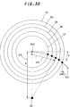
- Fig. 30 shows the turning radial locus of the head mounting arm of the signal reading head and clock marks and home index marks disposed on the locus.
- the reference numeral 500 denotes the center of the circular data tracks.
- Data tracks D3, D4, D5, D6 and D7 are formed concentrically around the center 500 and N clock marks CM are physically recorded on each of the data tracks at equal intervals.
- One home index mark HI is recorded on each circuit.
- These clock marks CM and home index marks HI are disposed on the turning radial locus 517 of the head mounting arm extending in the disk radial direction.
- the disk rotational radial distance 512 i.e. the head traveling track radius from the center of the track 500 (in Fig.30, the center 500 and the axis of rotation of the spindle are assumed to coincide) to the track where the signal reading head is located (the data track D5 in Fig.30)
- the phase difference angle between the home index position of the axis of rotation of the spindle and the home index marks recorded on the disk data track is indicated by ⁇
- the phase difference angle ⁇ changes along with changes in the disk rotational radial position of the head, i.e.
- the phase fluctuation of the home index mark reproducing signal may be obtained just by inputting r for a track being reproduced by calculating the phase difference angles ⁇ for various values of r beforehand and storing them in the form of a table.
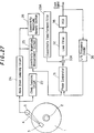
- Fig. 31 is a block diagram showing the construction of a fifth embodiment of the disc device of the present invention.
- a disk 1 on which N clock marks are recorded on each circular data track at equal intervals is chucked on a spindle 2.
- a recording and reproduction head 3 is mounted on a turnable arm 4 to move on the disk 1 to reproduce signals.
- the signals read out of the disk 1 by the head 3 are amplified by a reproduction and amplification circuit 21 and are converted into pulse signals PS at the TTL level by an A/D converting circuit 21A.
- the pulse signals PS are supplied to a clock sampling circuit 22A, a home index sampling circuit 24A and a track number sampling circuit 51.
- the clock sampling circuit 22A samples a clock mark reproduced signal CMS from the pulse signals PS and supplies it to an eccentricity magnitude measuring section 25C and a PLL circuit 30.
- the home index sampling circuit 24A samples a home index reproduced signal HIS and supplies it to the eccentricity magnitude measuring section 25C and a memory access section 53A of an adjustment section 53.
- the track number sampling circuit 51 samples a head traveling track number TN from the pulse signals PS and supplies it to the eccentricity magnitude measurement section 25C and a phase difference table 53P and multiplication coefficient table 53K of the adjustment section 53.
- the eccentricity magnitude measuring section 25C calculates the eccentricity (decentering) information (the fixed position phase shift magnitude) around the head traveling track using the clock mark reproduced signal CMS, the home index reproduced signal HIS and the head traveling track number TN. It also converts this eccentricity information into standard eccentricity information DI in standard track numbers (for example the inner track), finds the eccentricity magnitude (table), and outputs it to the eccentricity magnitude memory section 26C.
- a memory access section 53A in the adjustment section 53 outputs control and address signals to the eccentricity magnitude memory section 26C based on the home index reproduced signal HIS.
- the eccentricity magnitude memory section 26C memorizes the eccentricity DI output from the eccentricity magnitude measurement section 25C across the one circuit of the head traveling track according to the control and access signals from the memory access section 53A.
- the eccentric information memorized indicates the dislocation of the data track circle from the ideal locus circle.
- the phase difference table 53P in the adjusting section 53 memorizes the phase difference angle ⁇ between the home index position of the axis of rotation of the spindle and the home index mark recorded on the data track of the disk with the head traveling track number as an input parameter.
- the head traveling track number corresponds to the rotational radial distance of the disc of the head of Fig.30, i.e. the head traveling track radius r. Therefore, (Equation 20), the phase difference angle ⁇ changes as the traveling track number changes.
- the phase difference table 53P stores the phase difference angles ⁇ for values of various track numbers calculated beforehand in the form of a table and outputs the phase fluctuation of the home index mark reproducing signal as the phase difference angle ⁇ when the number of the track being reproduced, i.e. along which the head is traveling is inputted.
- the multiplication coefficient table 53K memorizes the values of the portion 2 ⁇ /( ⁇ N) * 2/r of Equation 19 when the head traveling track radius r which corresponds to the track number changes, as multiplication coefficients, in the form of a table.
- the phase difference table 53P When the head traveling track number TN is outputted from the track number sampling circuit 51, the phase difference table 53P outputs a phase difference ⁇ which corresponds to its track number TN.
- the memory access section 53A outputs the control and address signals that correspond to the phase difference ⁇ outputted from the phase difference table 53P to the eccentricity magnitude memory section 26C and corresponding to that, the eccentricity magnitude measurement section 25C supplies the eccentricity DI to one of the inputs of a multiplier 53M in the adjusting section 53.
- the multiplication coefficient table 53K supplies the multiplication coefficient that corresponds to the head traveling track number TN supplied from the track number sampling circuit 51 to the other input terminal of the multiplier 53M.
- the multiplier 53M multiplies the eccentricity DI input with the multiplication coefficient. That is, the multiplier 53M changes and outputs the dislocation, i.e. the eccentricity magnitude, read out of the eccentricity magnitude memory section 26C, corresponding to the head traveling track number.
- the eccentricity magnitude thus changed or adjusted is converted into an analog external control voltage by a D/A converting circuit 28 and applied to the PLL circuit 30 as a feed forward compensating value.
- the PLL circuit 30 changes the phase or frequency of the clock mark reproducing signal CMS in accordance with the input external control voltage.
- the embodiment shown in Fig. 31 allows the clock signal to follow up the eccentricity of the disk 1 with high accuracy.
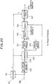
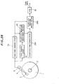
- Fig. 32 shows the construction of a sixth embodiment of the disc device of the present invention.
- the embodiment shown in Fig. 32 differs from that shown in Fig. 31 in that an angle sensor 61 and a head traveling radial position detecting circuit 62 are provided instead of the track number detecting circuit 51, an eccentricity magnitude measurement section 25D and eccentricity magnitude memory section 26D are provided instead of the eccentricity magnitude measurement section 25C, and an eccentricity magnitude memory section 26C and an adjusting section 63 containing a memory access section 63A, a multiplication section 63M, a phase difference table 63P and a multiplication coefficient table 63K are provided instead of the adjusting section 53 containing the memory access section 53A, the multiplication section 53M, the phase difference table 53P and the multiplication coefficient table 53K.
- the angle sensor 61 is mounted on the axis of rotation of the arm 4 to detect a rotational angle of the arm 4.
- the head traveling radial position detecting circuit 62 finds the head traveling track radius r (see Fig. 9) based on the rotational angle of the arm 4 detected by the sensor 61, and outputs it to the eccentricity magnitude measurement section 25D, phase difference table 63P and multiplication coefficient table 63K as a head traveling radial position signal HRP.
- the eccentricity magnitude measurement section 25D calculates the eccentricity information (phase shift magnitude at predetermined positions) around one circuit of the head traveling track, using the clock mark reproducing signal CMS, the home index reproducing signal HIS and the head traveling track radius r indicated by the head traveling radial position signal HRP. It also converts this eccentricity information into standard eccentricity information DI for a standard track number (for example the inner periphery track), finds the eccentricity magnitude (table), and outputs it to the eccentricity magnitude memory section 26D.
- the memory access section 63A in the adjusting section 63 outputs control and address signals to the eccentricity magnitude memory section 26D based on the home index reproduction signal HIS.
- the eccentricity magnitude memory section 26D memorizes the eccentricity DI output from the eccentricity magnitude measurement section 25D for one circuit of the head traveling track in accordance with the control and access signals from the memory access section 63A.
- the eccentricity information memorized indicates the dislocation of the data track circle from the ideal locus circle.
- the phase difference table 63P in the adjusting section 63 memorizes the phase difference angle ⁇ between the home index position of the axis of rotation of the spindle and the home index mark recorded on the data track of the disk with the head traveling track number as an input parameter. As seen from Equation 20, the phase difference angle ⁇ changes as the head traveling track radius r changes.
- the phase difference table 63P stores the phase difference angle ⁇ for various values of the radius r calculated beforehand in the form of a table and outputs the phase fluctuation of the home index mark reproducing signal as the phase difference angle ⁇ when a radius r of the track being reproduced or on which the head is traveling is input.
- the multiplication coefficient table 63K memorizes the values of the portion 2 ⁇ /( ⁇ N) * 2/r of Equation 19 when the radius r changes, as multiplication coefficients, in table form.
- the phase difference table 63P When the head traveling radial position signal HRP is output from the head traveling radial position detecting circuit 62, the phase difference table 63P outputs a phase difference ⁇ which corresponds to the radius r which the head traveling radial position signal HRP indicates.
- the memory access section 63A outputs the control and address signals that correspond to the phase difference ⁇ output from the phase difference table 63P to the eccentricity magnitude memory section 26D, and corresponding to that the eccentricity magnitude measurement section 25D supplies the eccentricity DI to one of the inputs of a multiplier 63M in the adjusting section 63.
- the multiplication coefficient table 63K supplies a multiplication coefficient that corresponds to the head traveling radial position signal HRP, i.e.
- the multiplier 63M multiplies the eccentricity DI input by the multiplication coefficient. That is, the multiplier 63M changes and outputs the dislocation, i.e. eccentricity, read out of the eccentricity magnitude memory section 26D corresponding to the radius r.
- the eccentricity thus changed or adjusted is converted into an analog external control voltage by the D/A converting circuit 28 and applied to the PLL circuit 30 as a feed forward compensating value.
- the PLL circuit 30 changes the phase or frequency of the clock mark reproducing signal CMS in accordance with the input external control voltage. Accordingly, the embodiment shown in Fig. 31 allows the clock signal to follow up the eccentricity of the disk 1 with high accuracy.
- the correction of the frequency fluctuation of the reproduced clock signal with respect to the fluctuation of the unit radius, caused by the offset between the center of axis of rotation and that of the data track circle when the disk is chucked on the spindle, may be optimized.
- the phase error due to the traveling radial position of the signal reading head may be optimized when the phases of the reproduced signals of the home index of the axis of rotation of the spindle and the home index physically recorded on the data track circles of the disk differ in the track numbers, i.e. in the head traveling track position.
- the phase or frequency of the clock signal outputted from the voltage controlled oscillator is corrected in accordance with a signal that corresponds to the eccentricity of the disk stored in the memory means, so that the clock signal correctly follows up the eccentricity of the disk.
- the signal that corresponds to the eccentricity of the disk memorized in the memory means is added to the output of the loop filter in synchronization with the rotation of the disk and is supplied to the voltage controlled oscillator, so that the clock signal correctly follows up the eccentricity of the disk.
- an eccentricity is measured for each of the plurality of disk faces, a signal that corresponds to the eccentricity is stored in the memory means for each disk face, a signal that corresponds to the eccentricity of the disk face to be accessed from among the plurality of disk faces is selectively read out and the phase or frequency of the clock signal output from the voltage controlled oscillator is changed based on the read out signal that corresponds to the eccentricity. Therefore, when the disk face to be accessed is changed, the clock signal immediately follows up the eccentricity of the disk.
Applications Claiming Priority (6)
| Application Number | Priority Date | Filing Date | Title |
|---|---|---|---|
| JP35057892 | 1992-12-04 | ||
| JP350578/92 | 1992-12-04 | ||
| JP57764/93 | 1993-02-23 | ||
| JP05776493A JP3374433B2 (ja) | 1992-12-04 | 1993-02-23 | クロック信号補正回路 |
| JP66248/93 | 1993-03-02 | ||
| JP06624893A JP3198490B2 (ja) | 1993-03-02 | 1993-03-02 | 偏心量測定装置 |
Publications (3)
| Publication Number | Publication Date |
|---|---|
| EP0600737A2 true EP0600737A2 (de) | 1994-06-08 |
| EP0600737A3 EP0600737A3 (en) | 1994-09-07 |
| EP0600737B1 EP0600737B1 (de) | 1998-06-17 |
Family
ID=27296373
Family Applications (1)
| Application Number | Title | Priority Date | Filing Date |
|---|---|---|---|
| EP93309668A Expired - Lifetime EP0600737B1 (de) | 1992-12-04 | 1993-12-02 | Plattenanordnung |
Country Status (4)
| Country | Link |
|---|---|
| US (4) | US5615191A (de) |
| EP (1) | EP0600737B1 (de) |
| KR (1) | KR100292038B1 (de) |
| DE (1) | DE69319209T2 (de) |
Cited By (3)
| Publication number | Priority date | Publication date | Assignee | Title |
|---|---|---|---|---|
| DE102008001874A1 (de) | 2008-05-20 | 2009-11-26 | Evonik Degussa Gmbh | Verfahren zur Herstellung von L-Aminosäuren |
| EP2762571A1 (de) | 2013-01-30 | 2014-08-06 | Evonik Industries AG | Mikroorganismus und Verfahren zur fermentativen Herstellung von Aminosäuren |
| EP2811028A1 (de) | 2013-06-03 | 2014-12-10 | Evonik Industries AG | Verfahren zur Herstellung von L-Leucin, L-Valin, L-Isoleucin, alpha-Ketoisovalerat, alpha-Keto-beta-Methylvalerat oder alpha-Ketoisocaproat unter Verwendung rekombinanter Corynebakterien enthaltend das durch Propionat induzierbare ilvBN-Operon |
Families Citing this family (56)
| Publication number | Priority date | Publication date | Assignee | Title |
|---|---|---|---|---|
| JPH09161411A (ja) * | 1995-12-11 | 1997-06-20 | Sony Corp | 再生クロック位相補正回路 |
| US5999357A (en) * | 1996-05-30 | 1999-12-07 | International Business Machines Corporation | Method and apparatus for spindle synchronization to reduce drive to drive runout |
| JP2965062B2 (ja) | 1996-06-10 | 1999-10-18 | 富士通株式会社 | ディスク装置及びディスク装置のヘッド位置制御方法 |
| US6049440A (en) * | 1996-10-23 | 2000-04-11 | Samsung Electronics Co., Ltd. | Self written read/write track servo parameter for spindle RRO compensation |
| JP3234177B2 (ja) * | 1997-07-01 | 2001-12-04 | ファナック株式会社 | 位置制御装置 |
| US6141175A (en) * | 1997-10-08 | 2000-10-31 | Western Digital Corporation | Repeatable runout cancellation in sectored servo disk drive positioning system |
| US6191904B1 (en) * | 1997-11-14 | 2001-02-20 | Castlewood Systems, Inc. | Data sector timing compensation technique based upon drive eccentricity |
| JP3865170B2 (ja) * | 1997-12-19 | 2007-01-10 | ソニー株式会社 | 位相同期装置及び位相同期方法 |
| US6768705B2 (en) | 1998-07-17 | 2004-07-27 | Fujitsu Limited | Optical disk drive including a positioner and means for compensating for an eccentricity of an optical disk |
| DE19964226C2 (de) * | 1998-07-17 | 2002-10-31 | Fujitsu Ltd | Optikplattenlaufwerk, umfassend eine Positioniervorrichtung, sowie Mittel zum Kompensieren einer Exzentrizität einer Optikplatte |
| DE19931841C2 (de) * | 1998-07-17 | 2003-04-10 | Fujitsu Ltd | Optikplattenlaufwerk, umfassend eine Positioniervorrichtung, sowie Mittel zum Kompensieren einer Exzentrizität einer Optikplatte |
| JP2000339709A (ja) * | 1999-05-27 | 2000-12-08 | Matsushita Electric Ind Co Ltd | 光ディスク記録再生装置 |
| JP2000357337A (ja) | 1999-06-15 | 2000-12-26 | Toshiba Corp | 光ディスク再生装置 |
| US7088650B1 (en) * | 1999-08-23 | 2006-08-08 | Worthington Mark O | Methods and apparatus for optical disc data acquisition using physical synchronization markers |
| JP4195154B2 (ja) * | 1999-08-31 | 2008-12-10 | ソニーマニュファクチュアリングシステムズ株式会社 | 位置検出装置及び演算処理装置 |
| JP2001076361A (ja) * | 1999-09-02 | 2001-03-23 | Sony Precision Technology Inc | ディスクの偏芯量の測定方法及び測定装置 |
| US6498772B1 (en) * | 1999-09-20 | 2002-12-24 | Matsushita Electric Industrial Co., Ltd. | Optical disc apparatus |
| JP3658252B2 (ja) * | 1999-10-01 | 2005-06-08 | シャープ株式会社 | 光ディスク記録再生装置 |
| US6765848B2 (en) * | 2001-01-10 | 2004-07-20 | Infineon Technologies North America Corp. | Focus and tracking repeatable runout compensator |
| US6628465B2 (en) | 2001-02-27 | 2003-09-30 | Trace Storage Technologies Corporation | Magnetic media defect detection apparatus and method |
| US7145855B2 (en) * | 2002-07-30 | 2006-12-05 | Media Tek Inc. | Method of controlling an optical disk drive by calculating a target frequency of a DPLL signal |
| JP4264532B2 (ja) * | 2002-11-19 | 2009-05-20 | ソニー株式会社 | ディスク基板および光ディスク |
| US20040156137A1 (en) * | 2003-02-06 | 2004-08-12 | Settje Christopher Thomas | Timing variance write gate pull |
| US7088534B2 (en) * | 2003-04-08 | 2006-08-08 | Marvell International Ltd. | Disk synchronous write |
| US7450483B2 (en) * | 2003-04-28 | 2008-11-11 | Panasonic Corporation | Information carrier apparatus and information carrier eccentricity correction method |
| KR100546349B1 (ko) * | 2003-07-23 | 2006-01-26 | 삼성전자주식회사 | 광 디스크 서보 시스템에서 디스크 편심 보상 장치 및 그방법 |
| TWI231490B (en) * | 2003-09-12 | 2005-04-21 | Mediatek Inc | Method for detecting eccentric disk and device thereof |
| JP2005174510A (ja) * | 2003-12-15 | 2005-06-30 | Toshiba Corp | ディスク記憶装置及びディスクシフト量算出方法 |
| JP4212504B2 (ja) * | 2004-03-31 | 2009-01-21 | 株式会社東芝 | ピックアップ制御装置および光ディスク装置 |
| JP2005353148A (ja) * | 2004-06-09 | 2005-12-22 | Fujitsu Ltd | ヘッド位置制御方法及びディスク装置 |
| US7397621B2 (en) * | 2004-06-14 | 2008-07-08 | Kla-Tencor Technologies Corporation | Servo pattern characterization on magnetic disks |
| US7333280B1 (en) | 2004-08-03 | 2008-02-19 | Western Digital Technologies, Inc. | Servo writing a disk drive by synchronizing a servo write clock to a reference pattern on the disk and compensating for repeatable phase error |
| US7068451B1 (en) * | 2004-11-16 | 2006-06-27 | Western Digital Technologies, Inc. | Disk drive estimating a sinusoidal error in a wedge time period due to eccentricity in disk rotation |
| US7057836B1 (en) * | 2004-11-19 | 2006-06-06 | Western Digital Technologies, Inc. | Disk drive servo controller utilizing an extended servo header |
| US7251098B1 (en) | 2004-11-19 | 2007-07-31 | Western Digital Technologies, Inc. | Disk drive adjusting write clock frequency to compensate for eccentricity in disk rotation |
| US6972540B1 (en) * | 2004-11-19 | 2005-12-06 | Western Digital Technologies, Inc. | Disk drive employing wedge spindle speed control with eccentricity compensation |
| US7502186B2 (en) * | 2005-04-01 | 2009-03-10 | Agency For Science Technology And Research | Disk drive clock tracking circuit, error compensation circuit and method |
| JP2007172733A (ja) | 2005-12-21 | 2007-07-05 | Toshiba Corp | ディスク記憶装置及びヘッド位置決め制御方法 |
| US7440225B1 (en) | 2006-08-21 | 2008-10-21 | Western Digital Technologies, Inc. | Disk drive employing pivot friction compensation |
| KR100771881B1 (ko) | 2006-08-23 | 2007-11-01 | 삼성전자주식회사 | 디스크 회전 슬립에 따른 데이터 섹터 위상 보정 방법 및이를 이용한 디스크 드라이브 |
| US7391584B1 (en) | 2006-11-07 | 2008-06-24 | Western Digital Technologies, Inc. | Compensating for repeatable phase error when servo writing a disk drive from spiral tracks |
| JP2008243322A (ja) * | 2007-03-28 | 2008-10-09 | Fujitsu Ltd | パターンドメディアクロック生成方法、パターンドメディア及び情報記録再生装置 |
| US7551390B1 (en) | 2007-08-21 | 2009-06-23 | Western Digital Technologies, Inc. | Disk drive to characterize misaligned servo wedges |
| US7583466B2 (en) * | 2007-11-15 | 2009-09-01 | Western Digital (Fremont), Llc | Disk drive determining operating fly height by detecting head disk contact from disk rotation time |
| US8022443B1 (en) | 2007-12-06 | 2011-09-20 | Marvell International Ltd. | Memory and interconnect design in fine pitch |
| US8004784B1 (en) | 2007-12-26 | 2011-08-23 | Marvell International Ltd. | Predictive methods and systems for sampling data read from a rotating storage medium |
| JP2010073295A (ja) * | 2008-09-22 | 2010-04-02 | Toshiba Storage Device Corp | 磁気記録装置、制御装置および磁気記録装置制御方法 |
| US7924519B2 (en) * | 2008-09-29 | 2011-04-12 | Wd Media, Inc. | Eccentricity determination for a disk |
| US8934192B1 (en) | 2008-11-24 | 2015-01-13 | Western Digital Technologies, Inc. | Disk drive determining operating fly height by detecting head disk contact from read signal amplitude variance |
| US8077426B2 (en) * | 2008-12-16 | 2011-12-13 | Guzik Technical Enterprises | Magnetic disk centering method and system |
| US8508879B1 (en) | 2010-01-21 | 2013-08-13 | Marvell International Ltd. | Write clock rephase for magnetic recording device |
| US8508878B1 (en) | 2010-01-21 | 2013-08-13 | Marvell International Ltd. | Write clock phase tracking for magnetic recording device |
| JP2012212489A (ja) | 2011-03-30 | 2012-11-01 | Hitachi High-Technologies Corp | 磁気ディスクまたは磁気ヘッドの検査装置及びその検査方法 |
| US8929021B1 (en) | 2012-03-27 | 2015-01-06 | Western Digital Technologies, Inc. | Disk drive servo writing from spiral tracks using radial dependent timing feed-forward compensation |
| US8917475B1 (en) * | 2013-12-20 | 2014-12-23 | Western Digital Technologies, Inc. | Disk drive generating a disk locked clock using radial dependent timing feed-forward compensation |
| JP2022105860A (ja) | 2021-01-05 | 2022-07-15 | 株式会社東芝 | 磁気ディスク装置及びヘッドチェンジ処理方法 |
Citations (7)
| Publication number | Priority date | Publication date | Assignee | Title |
|---|---|---|---|---|
| EP0082390A2 (de) * | 1981-12-21 | 1983-06-29 | Discovision Associates | Vorrichtung zum Detektieren der Exzentrizität einer Videoplatte und eines Videoplattenspielers |
| JPS60147975A (ja) * | 1984-01-11 | 1985-08-05 | Hitachi Ltd | ビデオデイスクプレ−ヤの検索装置 |
| DE3609460A1 (de) * | 1985-03-22 | 1986-10-16 | Hitachi, Ltd., Tokio/Tokyo | Zugriffsverfahren und informationswiedergewinnungsvorrichtung |
| EP0209692A2 (de) * | 1985-07-16 | 1987-01-28 | International Business Machines Corporation | Servoregelungssystem für eine Magnetplattenvorrichtung mit schneller Verminderung des mehrmaligen Kopfpositionsfehlers |
| JPS63108575A (ja) * | 1986-10-27 | 1988-05-13 | Ricoh Co Ltd | 磁気デイスクの偏心補正方式 |
| JPH01100777A (ja) * | 1987-10-14 | 1989-04-19 | Matsushita Electric Ind Co Ltd | フレキシブル磁気ディスク |
| JPH0325767A (ja) * | 1989-06-22 | 1991-02-04 | Sony Corp | 円盤状記録媒体駆動装置のヘッド位置制御装置 |
Family Cites Families (5)
| Publication number | Priority date | Publication date | Assignee | Title |
|---|---|---|---|---|
| US4414589A (en) * | 1981-12-14 | 1983-11-08 | Northern Telecom Inc. | Embedded servo track following system and method for writing servo tracks |
| JP2594914B2 (ja) * | 1986-07-11 | 1997-03-26 | 株式会社日立製作所 | 光デイスク装置 |
| US4764914A (en) * | 1987-09-11 | 1988-08-16 | Eastman Kodak Company | Least squares method and apparatus for determining track eccentricity of a disk |
| JPH03134865A (ja) * | 1989-10-19 | 1991-06-07 | Pioneer Electron Corp | 情報記録ディスク演奏装置 |
| JP3063230B2 (ja) * | 1991-05-31 | 2000-07-12 | ソニー株式会社 | 書き換え可能なディスクおよびディスク装置 |
-
1993
- 1993-12-01 KR KR1019930026099A patent/KR100292038B1/ko not_active IP Right Cessation
- 1993-12-02 EP EP93309668A patent/EP0600737B1/de not_active Expired - Lifetime
- 1993-12-02 DE DE69319209T patent/DE69319209T2/de not_active Expired - Fee Related
-
1995
- 1995-11-09 US US08/555,542 patent/US5615191A/en not_active Expired - Fee Related
-
1997
- 1997-03-21 US US08/821,330 patent/US5745455A/en not_active Expired - Lifetime
- 1997-03-21 US US08/821,328 patent/US5761165A/en not_active Expired - Fee Related
- 1997-03-21 US US08/821,329 patent/US5905705A/en not_active Expired - Fee Related
Patent Citations (7)
| Publication number | Priority date | Publication date | Assignee | Title |
|---|---|---|---|---|
| EP0082390A2 (de) * | 1981-12-21 | 1983-06-29 | Discovision Associates | Vorrichtung zum Detektieren der Exzentrizität einer Videoplatte und eines Videoplattenspielers |
| JPS60147975A (ja) * | 1984-01-11 | 1985-08-05 | Hitachi Ltd | ビデオデイスクプレ−ヤの検索装置 |
| DE3609460A1 (de) * | 1985-03-22 | 1986-10-16 | Hitachi, Ltd., Tokio/Tokyo | Zugriffsverfahren und informationswiedergewinnungsvorrichtung |
| EP0209692A2 (de) * | 1985-07-16 | 1987-01-28 | International Business Machines Corporation | Servoregelungssystem für eine Magnetplattenvorrichtung mit schneller Verminderung des mehrmaligen Kopfpositionsfehlers |
| JPS63108575A (ja) * | 1986-10-27 | 1988-05-13 | Ricoh Co Ltd | 磁気デイスクの偏心補正方式 |
| JPH01100777A (ja) * | 1987-10-14 | 1989-04-19 | Matsushita Electric Ind Co Ltd | フレキシブル磁気ディスク |
| JPH0325767A (ja) * | 1989-06-22 | 1991-02-04 | Sony Corp | 円盤状記録媒体駆動装置のヘッド位置制御装置 |
Non-Patent Citations (4)
| Title |
|---|
| PATENT ABSTRACTS OF JAPAN vol. 12, no. 359 (P-762) 27 September 1988 & JP-A-63 108 575 (RICOH) 13 May 1988 * |
| PATENT ABSTRACTS OF JAPAN vol. 13, no. 342 (P-908) 2 August 1989 & JP-A-01 100 777 (MATSUSHITA) 19 April 1989 * |
| PATENT ABSTRACTS OF JAPAN vol. 15, no. 156 (P-1192) 18 April 1991 & JP-A-03 025 767 (SONY) 4 February 1991 * |
| PATENT ABSTRACTS OF JAPAN vol. 9, no. 323 (P-414) 18 December 1985 & JP-A-60 147 975 (HITACHI) 5 August 1985 * |
Cited By (3)
| Publication number | Priority date | Publication date | Assignee | Title |
|---|---|---|---|---|
| DE102008001874A1 (de) | 2008-05-20 | 2009-11-26 | Evonik Degussa Gmbh | Verfahren zur Herstellung von L-Aminosäuren |
| EP2762571A1 (de) | 2013-01-30 | 2014-08-06 | Evonik Industries AG | Mikroorganismus und Verfahren zur fermentativen Herstellung von Aminosäuren |
| EP2811028A1 (de) | 2013-06-03 | 2014-12-10 | Evonik Industries AG | Verfahren zur Herstellung von L-Leucin, L-Valin, L-Isoleucin, alpha-Ketoisovalerat, alpha-Keto-beta-Methylvalerat oder alpha-Ketoisocaproat unter Verwendung rekombinanter Corynebakterien enthaltend das durch Propionat induzierbare ilvBN-Operon |
Also Published As
| Publication number | Publication date |
|---|---|
| KR100292038B1 (ko) | 2001-06-01 |
| DE69319209T2 (de) | 1998-12-10 |
| KR940016175A (ko) | 1994-07-22 |
| EP0600737B1 (de) | 1998-06-17 |
| US5905705A (en) | 1999-05-18 |
| US5761165A (en) | 1998-06-02 |
| US5745455A (en) | 1998-04-28 |
| US5615191A (en) | 1997-03-25 |
| EP0600737A3 (en) | 1994-09-07 |
| DE69319209D1 (de) | 1998-07-23 |
Similar Documents
| Publication | Publication Date | Title |
|---|---|---|
| EP0600737B1 (de) | Plattenanordnung | |
| KR0124052B1 (ko) | 고성능 디스크 드라이브, 이 디스크 드라이브내의 서보 섹터 패턴 및 이 디스크 드라이브에서 데이타 변환기 헤드의 위치를 결정하는 방법 | |
| US5138564A (en) | Automatic encoder calibration | |
| US7646557B2 (en) | Methods and apparatus for generating a clock signal, for writing servo tracks, and for characterising timing errors in a servo track writer | |
| JPS6218683A (ja) | デイスクフアイルのサ−ボ制御システム | |
| KR100623910B1 (ko) | 자기디스크의 편심제어방법 및 편심제어방법을 기록한기록매체, 및 편심제어방법을 사용한 자기디스크장치 | |
| US7233453B2 (en) | Servo track writing device and method thereof | |
| KR100278755B1 (ko) | 편심량 측정 장치 | |
| JPH0430092B2 (de) | ||
| JP2003516599A (ja) | 回転する情報担体を走査する装置 | |
| JP3374433B2 (ja) | クロック信号補正回路 | |
| JP2821629B2 (ja) | 光ディスクのクロック検出方法 | |
| JPH0714197A (ja) | アクチュエータ特性測定装置及びそれを使用した偏心補正装置 | |
| US6704258B2 (en) | Tracking error signal detector | |
| JPS60134786A (ja) | モ−タ速度制御装置 | |
| JP2560965B2 (ja) | 光ディスク記録再生装置 | |
| JPH1074359A (ja) | 光ディスク装置およびその線速度算出方法 | |
| JP2586605B2 (ja) | ディスク装置の位置決め装置 | |
| JPH06282941A (ja) | ディスク状媒体およびディスク装置 | |
| KR100523013B1 (ko) | 클록생성장치및디스크구동장치 | |
| JPH01211367A (ja) | 原盤記録装置の駆動制御回路 | |
| JPH0935289A (ja) | ピックアップ制御装置 | |
| JPH06162654A (ja) | 記録再生装置 | |
| JPH05343988A (ja) | 位相比較回路 | |
| JPH05128759A (ja) | デイスク装置 |
Legal Events
| Date | Code | Title | Description |
|---|---|---|---|
| PUAI | Public reference made under article 153(3) epc to a published international application that has entered the european phase |
Free format text: ORIGINAL CODE: 0009012 |
|
| AK | Designated contracting states |
Kind code of ref document: A2 Designated state(s): DE GB |
|
| PUAL | Search report despatched |
Free format text: ORIGINAL CODE: 0009013 |
|
| AK | Designated contracting states |
Kind code of ref document: A3 Designated state(s): DE GB |
|
| 17P | Request for examination filed |
Effective date: 19950210 |
|
| 17Q | First examination report despatched |
Effective date: 19970131 |
|
| GRAG | Despatch of communication of intention to grant |
Free format text: ORIGINAL CODE: EPIDOS AGRA |
|
| GRAG | Despatch of communication of intention to grant |
Free format text: ORIGINAL CODE: EPIDOS AGRA |
|
| GRAH | Despatch of communication of intention to grant a patent |
Free format text: ORIGINAL CODE: EPIDOS IGRA |
|
| GRAH | Despatch of communication of intention to grant a patent |
Free format text: ORIGINAL CODE: EPIDOS IGRA |
|
| GRAA | (expected) grant |
Free format text: ORIGINAL CODE: 0009210 |
|
| AK | Designated contracting states |
Kind code of ref document: B1 Designated state(s): DE GB |
|
| REF | Corresponds to: |
Ref document number: 69319209 Country of ref document: DE Date of ref document: 19980723 |
|
| PLBE | No opposition filed within time limit |
Free format text: ORIGINAL CODE: 0009261 |
|
| STAA | Information on the status of an ep patent application or granted ep patent |
Free format text: STATUS: NO OPPOSITION FILED WITHIN TIME LIMIT |
|
| 26N | No opposition filed | ||
| PGFP | Annual fee paid to national office [announced via postgrant information from national office to epo] |
Ref country code: GB Payment date: 20011205 Year of fee payment: 9 |
|
| PGFP | Annual fee paid to national office [announced via postgrant information from national office to epo] |
Ref country code: DE Payment date: 20011217 Year of fee payment: 9 |
|
| REG | Reference to a national code |
Ref country code: GB Ref legal event code: IF02 |
|
| PG25 | Lapsed in a contracting state [announced via postgrant information from national office to epo] |
Ref country code: GB Free format text: LAPSE BECAUSE OF NON-PAYMENT OF DUE FEES Effective date: 20021202 |
|
| PG25 | Lapsed in a contracting state [announced via postgrant information from national office to epo] |
Ref country code: DE Free format text: LAPSE BECAUSE OF NON-PAYMENT OF DUE FEES Effective date: 20030701 |
|
| GBPC | Gb: european patent ceased through non-payment of renewal fee |