EP0520342B1 - Messfahrzeug - Google Patents
Messfahrzeug Download PDFInfo
- Publication number
- EP0520342B1 EP0520342B1 EP92110434A EP92110434A EP0520342B1 EP 0520342 B1 EP0520342 B1 EP 0520342B1 EP 92110434 A EP92110434 A EP 92110434A EP 92110434 A EP92110434 A EP 92110434A EP 0520342 B1 EP0520342 B1 EP 0520342B1
- Authority
- EP
- European Patent Office
- Prior art keywords
- measuring
- measuring vehicle
- frame
- track
- plane
- Prior art date
- Legal status (The legal status is an assumption and is not a legal conclusion. Google has not performed a legal analysis and makes no representation as to the accuracy of the status listed.)
- Expired - Lifetime
Links
Images
Classifications
-
- E—FIXED CONSTRUCTIONS
- E01—CONSTRUCTION OF ROADS, RAILWAYS, OR BRIDGES
- E01B—PERMANENT WAY; PERMANENT-WAY TOOLS; MACHINES FOR MAKING RAILWAYS OF ALL KINDS
- E01B27/00—Placing, renewing, working, cleaning, or taking-up the ballast, with or without concurrent work on the track; Devices therefor; Packing sleepers
- E01B27/12—Packing sleepers, with or without concurrent work on the track; Compacting track-carrying ballast
- E01B27/13—Packing sleepers, with or without concurrent work on the track
- E01B27/16—Sleeper-tamping machines
- E01B27/17—Sleeper-tamping machines combined with means for lifting, levelling or slewing the track
-
- E—FIXED CONSTRUCTIONS
- E01—CONSTRUCTION OF ROADS, RAILWAYS, OR BRIDGES
- E01B—PERMANENT WAY; PERMANENT-WAY TOOLS; MACHINES FOR MAKING RAILWAYS OF ALL KINDS
- E01B35/00—Applications of measuring apparatus or devices for track-building purposes
-
- E—FIXED CONSTRUCTIONS
- E01—CONSTRUCTION OF ROADS, RAILWAYS, OR BRIDGES
- E01B—PERMANENT WAY; PERMANENT-WAY TOOLS; MACHINES FOR MAKING RAILWAYS OF ALL KINDS
- E01B2203/00—Devices for working the railway-superstructure
- E01B2203/16—Guiding or measuring means, e.g. for alignment, canting, stepwise propagation
Definitions
- the invention relates to a measuring vehicle according to the preamble of claim 1.
- Such a measuring vehicle is already known from a brochure "EM SAT Geometerwagen” from Plasser & Theurer. Above the frame level of the machine frame there is a spacious driving cabin and a powerful drive system.
- the second measuring vehicle referred to as a satellite car, is connected to a laser transmitter for generating a standing sight and can be connected to the machine frame for a joint transfer run below the frame level.
- US Pat. No. 4,691,565 already discloses a machine for measuring or registering and / or also for correcting the position of a track with a carriage that can be moved on the uncorrected track.
- This front carriage which is equipped with a laser transmitter and a travel drive, can be moved onto the machine for a joint transfer travel over an end area of a machine designed as a ramp.
- This machine which is designed as a track measuring car, has a laser receiver arranged in its front end region and various devices for determining and storing the track position correction values.
- the object of the present invention is to create a measuring vehicle of the type described in the introduction, which can be used in a particularly rational manner with reduced design effort.
- a measuring vehicle of this type with a low overall height and having a satellite car can be coupled in a particularly advantageous manner for a joint transfer to the place of use with a track-laying machine, in particular a tamping machine.
- the machine group can be controlled in a particularly efficient manner from the driver's cabin of the tamping machine without impairing visibility.
- This combined transfer travel enables a particularly simple construction of the measuring vehicle with an auxiliary motor that is only required for work and with a correspondingly low output, but a sufficiently large overall length of the vehicle frame for a satisfactory driving result during the transfer trip is possible due to the corresponding angular range of the limiting plane.
- such a measuring vehicle can also be coupled to a tamping machine already in use with a satellite car without any design effort or conversion work.
- a transfer run in a common machine group with a tamping machine enables the track to be measured and tamped in a single track lock, and the logistical effort can also be reduced considerably in comparison to previous separate work assignments.
- the remotely controllable solution of the pulling hook according to claim 4 enables a particularly rapid separation immediately after reaching the track construction site, while avoiding leaving the machine, which jeopardizes safety.
- the vehicle frame can be positively connected to the axle bearing, so that an influence of the suspension on the measurement result is reliably excluded.
- measuring vehicle Another further development of the measuring vehicle according to claim 12 enables problem-free and rapid attachment of the satellite vehicle below the projecting vehicle frame, so that the measuring vehicle can be incorporated into a train set unhindered.
- the development according to claim 13 enables the transport of the satellite car on the vehicle frame, with the ramp ensuring a rapid transfer of the satellite car from the transfer position to the working position.
- the refinement according to claim 15 enables exact adjustment of the correction work to be carried out by the tamping machine to the difference values between the actual and target position of the track, which were determined immediately beforehand by the measuring vehicle and the satellite car.
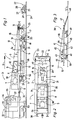
- the measuring vehicle 1 shown in FIG. 1 has a vehicle frame 2 with a frame plane 3 which runs parallel to a reference plane formed by wheel contact points 4 of rail bogies 5. This parallelism relates to the normal case in which the chassis springs of both rail bogies 5 are loaded to the same extent.
- An internal combustion engine 7 is arranged on the frame level 3 in the area of the rear machine end 6.
- a driving cabin 9 with a control device 10 is arranged upstream of this in the working direction of the measuring vehicle 1, indicated by an arrow 8.
- the driver's cabin 9 is located in a recess 11 of the vehicle frame 2.
- the upper contour lines 12 formed by the motor 7 and the driver's cabin 9 are arranged below a boundary plane 13 which is related to the reference plane or the reference plane formed by the wheel contact points 4 of the rail bogies 5.
- the frame plane 3 includes an angle ⁇ of 5 to 10 °.
- the boundary plane 13 forms with the frame plane 3 in the front end of the measuring vehicle 1 in the working direction perpendicular to the machine longitudinal direction and cutting line 14 running parallel to the frame or reference plane.
- the measuring vehicle 1 can be moved independently with the aid of its own travel drive 52.
- a measuring carriage 16 Beneath the frame level 3 and immediately in front of the front rail chassis 5 there is a measuring carriage 16 which is connected to the vehicle frame 2 by height-adjustable drives and has wheel flanges 15.
- a laser receiver 17 with a CCD matrix camera, a bank angle sensor 18 and two video cameras 19 lying opposite one another in the machine transverse direction for video-technical scanning of the rail section located in the region of each flanged wheel 15 are arranged on this.
- the laser receiver 17 is mounted on the measuring carriage 16 by drives 20 which can be adjusted in height and crosswise. This is also associated with a displacement measuring device 21 with a feeler roller that can be rolled on the rail head.
- the length of the vehicle frame 2 projecting beyond the front rail running gear 5 is greater than the total length of a satellite car 22. This can be lifted off a track 24 by a device 23 having drives and can be connected to the front end of the vehicle frame 2. As indicated by dash-dotted lines, the satellite car 22 is located during the transfer run in the section of the vehicle frame 2 protruding beyond the front rail running gear 5, so that it can be coupled to another machine unhindered.
- the satellite car 22 has wheel flanges which can be moved on the track 24, an auxiliary motor 25, a seat 26 and a laser transmitter 27. This is mounted on a transverse adjustment device 28 and can be moved up to 500 mm from the middle of the track.
- the two rail bogies 5 of the measuring vehicle 1 have locking drives 29, which can be acted upon hydraulically, between the axle bearing and the bogie frame, by means of which the influence of the bogie suspension can be switched off during the measuring process.
- a pull hook 30 arranged in the working direction at the rear end of the machine is designed for a remotely controllable solution of a coupling formed with a connected machine.
- the measuring vehicle 1 is for the transfer run with a tamping machine 32 coupled.
- a tamping machine 32 coupled to the measuring vehicle 1 .
- These are only partial Shown and shown in the usual way with tamping units, a track lifting straightening unit, a leveling and straightening reference system 33 and a travel drive 53 is equipped with a driving cabin 34 in its front end region in the working direction.
- This driving cabin 34 has a viewing area 35, from which the operator has a clear view of the track 24 during the transfer run. This clear view is ensured in spite of the pre-arrangement of the measuring vehicle 1 in that the upper contour lines 12 are arranged below the already precisely defined boundary plane 13.
- the pulling hook 30 is remotely released and the measuring vehicle 1 together with the satellite car 22 is moved one to two hundred meters away from the tamping machine 32 on the track 24.
- the right of way of the measuring vehicle 1 is stopped and the satellite car 22 is released from the device 23 or the vehicle frame 2 and lowered onto the track 24.
- the satellite car 22 is then moved up to the next fixed track point and positioned in relation to a color marking on the rail. Then the actual distance and the actual height of the track 24 to the track fixed point is measured.
- the determined data are transmitted to the measuring vehicle 1 by radio. After this measurement at the fixed track point, the satellite car 22 is moved about 5 to 10 m further and parked there.
- the laser transmitter 27 is set up on the laser receiver 17, which has meanwhile been lowered onto the track 24 with the measuring carriage 16.
- the satellite wagon 22 is fixed to a rail of the track by means of a suitable mechanical clamping device, so that movement by passing trains is excluded.
- the measuring vehicle 1 After the laser transmitter 27 has been set up on the receiver 17, the measuring vehicle 1 begins to measure the track section located between the measuring vehicle 1 and the satellite car 22. The height and the direction are measured simultaneously via the CCD matrix camera located in the laser receiver 17. The corresponding actual arrow heights at the predetermined distance are calculated from the increase in the track width of the position of the laser receiver 17 and the adjustment paths, as well as the distance covered, measured by the path measuring device 21. The calculation is only started when the measuring vehicle 1 has arrived at the fixed track point immediately in front of the satellite car 22 and has been stopped precisely in relation to this fixed track point. Only then can the arbitrary position of the chord formed by the laser transmitter 27 be mathematically converted to the theoretical chord on which the target arrow heights are based.
- the satellite car 22 can again be moved to the next fixed track point with the aid of its own auxiliary motor 25. After calculating the actual arrow heights, they are compared with the stored target arrow heights and the corresponding displacement and height correction values are determined. These correction data are then transmitted with the aid of a radio device 36 to the central control device 37 of the tamping machine 32 and can be processed further by this or by an automatic control computer for a corresponding control of the drives of the track lifting and straightening unit.
- the laser beam generated by the laser transmitter 27 is not split up, but rather is directed onto the receiver 17 as a beam with a circular cross section. This brings the advantages of higher intensity when receiving and thus also ensures reliable reception.
- the possibility of adjusting the laser transmitter 27 with the aid of the transverse adjusting device 28 has the advantage that the arrow 17 is smaller for the receiver 17. The other oblique position of the laser tendon would have to be adjusted in a larger area.
- the CCD matrix camera of the laser receiver 17 is a YZ adjustment device (transverse adjustment Y, height adjustment Z). Since the active reception area of the camera is too small for the necessary reception area, it must be adjusted accordingly. This is done continuously with a computer and an appropriate adjustment unit.
- the Z adjustment range is 500 mm, the Y adjustment range 1000 mm.
- the position of the camera on the adjustment unit is measured using an absolute encoder.
- the laser point is projected onto the CCD camera via a focusing screen and an optical system and its position is calculated by a computer with a corresponding program and transmitted to a main computer 38 of the measuring vehicle 1.
- the two video cameras 19 located on the measuring carriage 16 it is possible to use a monitor image generated in the driving cabin 9 to carry out the exact positioning of the measuring vehicle 1 in relation to a corresponding fixed point on the track. This is done by positioning the wheel center of the measuring carriage 16 on a color marking attached to the rail head and web.
- the measuring axis formed by the flanged wheels 15 is simultaneously designed as a telescopic axis so that the track width can be measured.
- the three-part system 31 is connected to a machine unit by connecting the satellite car 22 to the front machine end of the measuring vehicle 1 through the device 23 and coupling the measuring vehicle 1 itself to the tamping machine 32 by the pull hook 30.
- the operator can move the system freely from the driving cabin 34 in the direction of arrow 8.
- a variant of a further measuring vehicle 39 which can be seen in FIG. 3 has a vehicle frame 42 which is supported on rail undercarriages 40 and has a frame plane 41 running parallel to the track plane.
- a central control device 43 with a seat 44 is arranged on the rear end of the vehicle frame 42 in the working direction.
- a parking space for an independently movable satellite car 45 This can be moved on rails 46 running in the machine longitudinal direction and connected to the vehicle frame 42 and via a ramp 47 arranged in the front end region of the vehicle frame (see dash-dotted lines).
- the ramp 47 can be swiveled back into a rest position by drives for the transfer travel and work use, in which it comes to lie approximately parallel to the frame plane 41 directly above the vehicle frame 42.
- the measuring vehicle 39 can be moved with the aid of a motor 49 and a travel drive 50.
- a boundary plane 51 defined according to claim 1 includes an angle of 8 ° with the frame plane 41.
- the satellite car 45 located on the vehicle frame 42, the control device 43 and the seat 44 are located below this delimitation level 51, so that an unimpeded view of the track is provided by a tamping machine connected in the rear end area for the joint transfer run.
Applications Claiming Priority (2)
| Application Number | Priority Date | Filing Date | Title |
|---|---|---|---|
| AT1287/91 | 1991-06-27 | ||
| AT128791 | 1991-06-27 |
Publications (2)
| Publication Number | Publication Date |
|---|---|
| EP0520342A1 EP0520342A1 (de) | 1992-12-30 |
| EP0520342B1 true EP0520342B1 (de) | 1995-12-06 |
Family
ID=3510629
Family Applications (1)
| Application Number | Title | Priority Date | Filing Date |
|---|---|---|---|
| EP92110434A Expired - Lifetime EP0520342B1 (de) | 1991-06-27 | 1992-06-20 | Messfahrzeug |
Country Status (18)
| Country | Link |
|---|---|
| US (1) | US5301548A (zh) |
| EP (1) | EP0520342B1 (zh) |
| JP (1) | JP2865950B2 (zh) |
| CN (1) | CN1044021C (zh) |
| AT (1) | ATE131232T1 (zh) |
| AU (1) | AU646743B2 (zh) |
| CA (1) | CA2070791C (zh) |
| CZ (1) | CZ278676B6 (zh) |
| DE (1) | DE59204556D1 (zh) |
| DK (1) | DK0520342T3 (zh) |
| ES (1) | ES2081523T3 (zh) |
| FI (1) | FI98314C (zh) |
| HU (1) | HU212948B (zh) |
| NO (1) | NO301599B1 (zh) |
| PL (1) | PL168287B1 (zh) |
| RU (1) | RU2041310C1 (zh) |
| SK (1) | SK280109B6 (zh) |
| ZA (1) | ZA924770B (zh) |
Cited By (1)
| Publication number | Priority date | Publication date | Assignee | Title |
|---|---|---|---|---|
| RU2538482C1 (ru) * | 2013-08-08 | 2015-01-10 | Открытое акционерное общество "БетЭлТранс" (ОАО "БЭТ") | Система автоматизированного контроля геометрических параметров шпал |
Families Citing this family (38)
| Publication number | Priority date | Publication date | Assignee | Title |
|---|---|---|---|---|
| CZ285403B6 (cs) * | 1995-03-16 | 1999-08-11 | Franz Plasser Bahnbaumaschinen-Industriegesellschaft M. B. H. | Pracovní vozidlo pro provádění kolejových stavebních prací |
| AT405425B (de) * | 1997-08-20 | 1999-08-25 | Plasser Bahnbaumasch Franz | Gleisbaumaschine mit einem laser-bezugsystem und verfahren |
| EP0952254B1 (de) * | 1998-03-27 | 2003-11-19 | Franz Plasser Bahnbaumaschinen-Industriegesellschaft m.b.H. | Verfahren zur Gleislagekorrektur |
| US6161429A (en) * | 1998-10-13 | 2000-12-19 | Paveset America, Llc | Dual path profilograph |
| ATA18499A (de) * | 1999-02-10 | 2000-04-15 | Plasser Bahnbaumasch Franz | Verfahren zur lagekorrektur eines gleises |
| DE50015765D1 (de) * | 1999-02-12 | 2009-12-03 | Plasser Bahnbaumasch Franz | Verfahren zum Aufmessen eines Gleises |
| US6405141B1 (en) * | 2000-03-02 | 2002-06-11 | Ensco, Inc. | Dynamic track stiffness measurement system and method |
| SE516170C2 (sv) * | 2000-03-29 | 2001-11-26 | Railvac Ab | Sätt att planera banvallssidor och lasermätningsanordning |
| ITVE20000023A1 (it) * | 2000-05-12 | 2001-11-12 | Tecnogamma S A S Di Zanin E & | Apparecchiatura laser per il controllo delle rotaie di una linea ferrotramviaria. |
| US9733625B2 (en) | 2006-03-20 | 2017-08-15 | General Electric Company | Trip optimization system and method for a train |
| US10308265B2 (en) | 2006-03-20 | 2019-06-04 | Ge Global Sourcing Llc | Vehicle control system and method |
| AT6219U3 (de) * | 2002-07-23 | 2004-07-26 | Plasser Bahnbaumasch Franz | Verfahren zur beladung eines verladezuges |
| AT5982U3 (de) * | 2002-11-13 | 2003-12-29 | Plasser Bahnbaumasch Franz | Verfahren zur abtastung eines bettungsprofiles |
| US9950722B2 (en) | 2003-01-06 | 2018-04-24 | General Electric Company | System and method for vehicle control |
| US6804621B1 (en) * | 2003-04-10 | 2004-10-12 | Tata Consultancy Services (Division Of Tata Sons, Ltd) | Methods for aligning measured data taken from specific rail track sections of a railroad with the correct geographic location of the sections |
| US9956974B2 (en) | 2004-07-23 | 2018-05-01 | General Electric Company | Vehicle consist configuration control |
| US9828010B2 (en) | 2006-03-20 | 2017-11-28 | General Electric Company | System, method and computer software code for determining a mission plan for a powered system using signal aspect information |
| CN100371198C (zh) * | 2006-03-27 | 2008-02-27 | 太原理工大学 | 递推式铁路轨道检测车及检测方法 |
| US8914171B2 (en) | 2012-11-21 | 2014-12-16 | General Electric Company | Route examining system and method |
| CN101700777B (zh) * | 2009-10-24 | 2011-09-28 | 株洲南车时代电气股份有限公司 | 一种轨道几何参数测量小车 |
| CN102101478A (zh) * | 2009-12-19 | 2011-06-22 | 襄樊金鹰轨道车辆有限责任公司 | 车载作业车 |
| WO2014026091A2 (en) | 2012-08-10 | 2014-02-13 | General Electric Company | Route examining system and method |
| US9702715B2 (en) | 2012-10-17 | 2017-07-11 | General Electric Company | Distributed energy management system and method for a vehicle system |
| CN103046442B (zh) * | 2012-12-18 | 2015-03-11 | 北京二七轨道交通装备有限责任公司 | 打磨车激光定位装置及打磨车 |
| US9255913B2 (en) | 2013-07-31 | 2016-02-09 | General Electric Company | System and method for acoustically identifying damaged sections of a route |
| AT514667B1 (de) * | 2013-08-07 | 2015-05-15 | Plasser & Theurer Export Von Bahnbaumaschinen Gmbh | Verfahren zur Unterstopfung eines Gleises |
| AT514718B1 (de) * | 2013-09-11 | 2015-06-15 | Plasser & Theurer Export Von Bahnbaumaschinen Gmbh | Verfahren für die Korrektur eines Gleises |
| US20150083914A1 (en) * | 2013-09-25 | 2015-03-26 | Nordco Inc. | Railway reference machine having a collapsible projector assembly |
| EP2960371B1 (de) * | 2014-06-27 | 2017-08-09 | HP3 Real GmbH | Vorrichtung zum Vermessen von Gleisen |
| CN104652197A (zh) * | 2015-02-13 | 2015-05-27 | 中铁第一勘察设计院集团有限公司 | 高速铁路轨道测量仪分离式行走轮驱动装置 |
| WO2016153486A1 (en) * | 2015-03-24 | 2016-09-29 | Harsco Technologies LLC | Moveable seat on a rail vehicle |
| AT518839B1 (de) * | 2016-07-11 | 2018-12-15 | Plasser & Theurer Exp Von Bahnbaumaschinen G M B H | System und Verfahren zum Vermessen eines Gleises |
| AT519575B1 (de) * | 2017-02-15 | 2018-08-15 | Plasser & Theurer Export Von Bahnbaumaschinen Gmbh | Gleismessfahrzeug und Verfahren zur Erfassung einer vertikalen Gleislage |
| AT519784B1 (de) * | 2017-03-17 | 2019-11-15 | Plasser & Theurer Export Von Bahnbaumaschinen Gmbh | Maschine und Verfahren zum Profilieren und Verteilen von Schotter eines Gleises |
| CN110116734A (zh) * | 2019-05-07 | 2019-08-13 | 中国铁建重工集团股份有限公司 | 磁浮轨道作业车 |
| CN112442927A (zh) * | 2019-09-02 | 2021-03-05 | 中国铁道科学研究院集团有限公司铁道建筑研究所 | 一种捣固车前端偏差测量方法 |
| RU199383U1 (ru) * | 2020-02-04 | 2020-08-31 | Общество с ограниченной ответственностью "РН-Пурнефтегаз" | Каретка для дистанционного перемещения отражателя по рельсе |
| CN114987565B (zh) * | 2022-06-17 | 2023-08-04 | 杭州申昊科技股份有限公司 | 一种具有越障功能的轨道探伤车 |
Family Cites Families (3)
| Publication number | Priority date | Publication date | Assignee | Title |
|---|---|---|---|---|
| GB1154311A (en) * | 1965-03-23 | 1969-06-04 | Canron Ltd | Railway Track Lifting Apparatus |
| US3750299A (en) * | 1969-01-22 | 1973-08-07 | Plasser Bahnbaumasch Franz | Track apparatus with laser beam reference |
| ATE33411T1 (de) * | 1985-08-22 | 1988-04-15 | Plasser Bahnbaumasch Franz | Gleisfahrbare maschine zum messen bzw. registrieren oder korrigieren der gleislage mit laser-strahlen bzw. -ebenen. |
-
1992
- 1992-06-03 RU SU925011692A patent/RU2041310C1/ru active
- 1992-06-04 NO NO922200A patent/NO301599B1/no not_active IP Right Cessation
- 1992-06-09 CA CA002070791A patent/CA2070791C/en not_active Expired - Lifetime
- 1992-06-18 US US07/900,910 patent/US5301548A/en not_active Expired - Lifetime
- 1992-06-20 ES ES92110434T patent/ES2081523T3/es not_active Expired - Lifetime
- 1992-06-20 AT AT92110434T patent/ATE131232T1/de not_active IP Right Cessation
- 1992-06-20 EP EP92110434A patent/EP0520342B1/de not_active Expired - Lifetime
- 1992-06-20 DK DK92110434.5T patent/DK0520342T3/da not_active Application Discontinuation
- 1992-06-20 DE DE59204556T patent/DE59204556D1/de not_active Expired - Fee Related
- 1992-06-23 PL PL92294986A patent/PL168287B1/pl not_active IP Right Cessation
- 1992-06-24 CN CN92105036A patent/CN1044021C/zh not_active Expired - Fee Related
- 1992-06-25 HU HU9202115A patent/HU212948B/hu not_active IP Right Cessation
- 1992-06-26 JP JP4169393A patent/JP2865950B2/ja not_active Expired - Fee Related
- 1992-06-26 CZ CS921983A patent/CZ278676B6/cs not_active IP Right Cessation
- 1992-06-26 ZA ZA924770A patent/ZA924770B/xx unknown
- 1992-06-26 AU AU18621/92A patent/AU646743B2/en not_active Ceased
- 1992-06-26 SK SK1983-92A patent/SK280109B6/sk not_active IP Right Cessation
- 1992-06-26 FI FI922974A patent/FI98314C/fi active
Cited By (1)
| Publication number | Priority date | Publication date | Assignee | Title |
|---|---|---|---|---|
| RU2538482C1 (ru) * | 2013-08-08 | 2015-01-10 | Открытое акционерное общество "БетЭлТранс" (ОАО "БЭТ") | Система автоматизированного контроля геометрических параметров шпал |
Also Published As
| Publication number | Publication date |
|---|---|
| ZA924770B (en) | 1993-03-31 |
| SK280109B6 (sk) | 1999-08-06 |
| NO922200D0 (no) | 1992-06-04 |
| CA2070791C (en) | 2002-12-31 |
| PL294986A1 (en) | 1992-12-28 |
| EP0520342A1 (de) | 1992-12-30 |
| AU1862192A (en) | 1993-01-07 |
| NO301599B1 (no) | 1997-11-17 |
| CA2070791A1 (en) | 1992-12-18 |
| US5301548A (en) | 1994-04-12 |
| JP2865950B2 (ja) | 1999-03-08 |
| AU646743B2 (en) | 1994-03-03 |
| DK0520342T3 (da) | 1996-01-08 |
| FI922974A (fi) | 1992-12-28 |
| PL168287B1 (pl) | 1996-01-31 |
| RU2041310C1 (ru) | 1995-08-09 |
| CN1067938A (zh) | 1993-01-13 |
| JPH05202506A (ja) | 1993-08-10 |
| HU212948B (en) | 1996-12-30 |
| ATE131232T1 (de) | 1995-12-15 |
| FI98314B (fi) | 1997-02-14 |
| NO922200L (no) | 1992-12-28 |
| FI922974A0 (fi) | 1992-06-26 |
| CZ198392A3 (en) | 1993-01-13 |
| FI98314C (fi) | 1997-05-26 |
| DE59204556D1 (de) | 1996-01-18 |
| CZ278676B6 (en) | 1994-04-13 |
| CN1044021C (zh) | 1999-07-07 |
| HU9202115D0 (en) | 1992-10-28 |
| ES2081523T3 (es) | 1996-03-16 |
| HUT64276A (en) | 1993-12-28 |
| SK198392A3 (en) | 1994-08-10 |
Similar Documents
| Publication | Publication Date | Title |
|---|---|---|
| EP0520342B1 (de) | Messfahrzeug | |
| EP1028325B1 (de) | Verfahren zum Aufmessen eines Gleises | |
| EP0213253B1 (de) | Gleisfahrbare Maschine zum Messen bzw. Registrieren oder Korrigieren der Gleislage mit Laser-Strahlen bzw. -Ebenen | |
| EP3358079B1 (de) | Verfahren und vorrichtung zum messen und berechnen einer gleislage | |
| AT403066B (de) | Verfahren zum ermitteln der abweichungen der ist-lage eines gleisabschnittes | |
| EP0511191B1 (de) | Einrichtung zum Messen der Lage eines Gleises zu einem Fixpunkt | |
| DE3137194A1 (de) | Gleisverfahrbare einrichtung zur lage-ermittlung zum nachbargleis | |
| EP2839078B1 (de) | Maschine zur instandhaltung eines gleises | |
| EP3535456B1 (de) | Gleisbaumaschine mit gleislagemesssystem | |
| AT516343B1 (de) | Verfahren zum Ermitteln der Lage der Oberleitung bzw. der Stromschiene für Fahrzeuge | |
| EP0424811A1 (de) | Bezugsystem für Gleisbaumaschinen | |
| EP0732451A1 (de) | Arbeitsfahrzeug zur Durchführung von Gleisbauarbeiten | |
| EP1028193B1 (de) | Verfahren zur Lagekorrektur eines Gleises | |
| EP0652325B1 (de) | Gleisbaumaschine zur Korrektur der Gleislage | |
| AT4766U2 (de) | Gleisbaumaschine und verfahren zur erfassung einer gleislage | |
| EP1001085A1 (de) | Verfahren und Stopfmaschine zum Unterstopfen eines Gleises | |
| EP4251491A1 (de) | Verfahren und system zur ermittlung von korrekturwerten für eine lagekorrektur eines gleises | |
| DE102006027852B4 (de) | Gleismeßfahrzeug | |
| CA1095333A (en) | Mobile track leveling, lining and tamping machine | |
| AT514718A1 (de) | Verfahren für die Korrektur eines Gleises | |
| EP0731217B1 (de) | Stopfmaschine, Maschineanordnung und Verfahren zum Unterstopfen eines Gleises | |
| EP0722013B1 (de) | Verfahren und Gleisbaumaschine zur Durchführung von Gleisbauarbeiten | |
| EP4008838A1 (de) | Stopfmaschine zum unterstopfen von schwellen eines gleises | |
| DE102016008487A1 (de) | Vorrichtung zur Unterstützung des Aufgleisens eines Zweiwegefahrzeugs und Verfahren zum Aufgleisen eines solchen | |
| EP4130379A1 (de) | Verfahren zur berichtigung des seitenabstandes und des höhenabstandes einer bahnsteigkante eines bahnsteiges zur gleisachse |
Legal Events
| Date | Code | Title | Description |
|---|---|---|---|
| PUAI | Public reference made under article 153(3) epc to a published international application that has entered the european phase |
Free format text: ORIGINAL CODE: 0009012 |
|
| AK | Designated contracting states |
Kind code of ref document: A1 Designated state(s): AT BE CH DE DK ES FR GB IT LI NL SE |
|
| 17P | Request for examination filed |
Effective date: 19930518 |
|
| 17Q | First examination report despatched |
Effective date: 19940613 |
|
| GRAA | (expected) grant |
Free format text: ORIGINAL CODE: 0009210 |
|
| AK | Designated contracting states |
Kind code of ref document: B1 Designated state(s): AT BE CH DE DK ES FR GB IT LI NL SE |
|
| REF | Corresponds to: |
Ref document number: 131232 Country of ref document: AT Date of ref document: 19951215 Kind code of ref document: T |
|
| ITF | It: translation for a ep patent filed |
Owner name: ING. A. GIAMBROCONO & C. S.R.L. |
|
| REG | Reference to a national code |
Ref country code: DK Ref legal event code: T3 |
|
| REF | Corresponds to: |
Ref document number: 59204556 Country of ref document: DE Date of ref document: 19960118 |
|
| GBT | Gb: translation of ep patent filed (gb section 77(6)(a)/1977) |
Effective date: 19960116 |
|
| REG | Reference to a national code |
Ref country code: CH Ref legal event code: NV Representative=s name: DIPL.-ING. ETH H. R. WERFFELI PATENTANWALT |
|
| REG | Reference to a national code |
Ref country code: ES Ref legal event code: FG2A Ref document number: 2081523 Country of ref document: ES Kind code of ref document: T3 |
|
| ET | Fr: translation filed | ||
| PLBE | No opposition filed within time limit |
Free format text: ORIGINAL CODE: 0009261 |
|
| STAA | Information on the status of an ep patent application or granted ep patent |
Free format text: STATUS: NO OPPOSITION FILED WITHIN TIME LIMIT |
|
| 26N | No opposition filed | ||
| REG | Reference to a national code |
Ref country code: GB Ref legal event code: IF02 |
|
| PGFP | Annual fee paid to national office [announced via postgrant information from national office to epo] |
Ref country code: NL Payment date: 20090528 Year of fee payment: 18 Ref country code: DK Payment date: 20090526 Year of fee payment: 18 |
|
| PGFP | Annual fee paid to national office [announced via postgrant information from national office to epo] |
Ref country code: FR Payment date: 20090526 Year of fee payment: 18 Ref country code: SE Payment date: 20090528 Year of fee payment: 18 |
|
| PGFP | Annual fee paid to national office [announced via postgrant information from national office to epo] |
Ref country code: BE Payment date: 20090602 Year of fee payment: 18 |
|
| PGFP | Annual fee paid to national office [announced via postgrant information from national office to epo] |
Ref country code: CH Payment date: 20090526 Year of fee payment: 18 |
|
| PGFP | Annual fee paid to national office [announced via postgrant information from national office to epo] |
Ref country code: DE Payment date: 20090811 Year of fee payment: 18 |
|
| PGFP | Annual fee paid to national office [announced via postgrant information from national office to epo] |
Ref country code: ES Payment date: 20100519 Year of fee payment: 19 |
|
| PGFP | Annual fee paid to national office [announced via postgrant information from national office to epo] |
Ref country code: AT Payment date: 20100511 Year of fee payment: 19 Ref country code: IT Payment date: 20100624 Year of fee payment: 19 |
|
| PGFP | Annual fee paid to national office [announced via postgrant information from national office to epo] |
Ref country code: GB Payment date: 20100428 Year of fee payment: 19 |
|
| BERE | Be: lapsed |
Owner name: FRANZ *PLASSER BAHNBAUMASCHINEN- INDUSTRIEGESELLSC Effective date: 20100630 |
|
| REG | Reference to a national code |
Ref country code: NL Ref legal event code: V1 Effective date: 20110101 |
|
| REG | Reference to a national code |
Ref country code: CH Ref legal event code: PL Ref country code: DK Ref legal event code: EBP |
|
| EUG | Se: european patent has lapsed | ||
| REG | Reference to a national code |
Ref country code: FR Ref legal event code: ST Effective date: 20110228 |
|
| PG25 | Lapsed in a contracting state [announced via postgrant information from national office to epo] |
Ref country code: CH Free format text: LAPSE BECAUSE OF NON-PAYMENT OF DUE FEES Effective date: 20100630 Ref country code: LI Free format text: LAPSE BECAUSE OF NON-PAYMENT OF DUE FEES Effective date: 20100630 Ref country code: DE Free format text: LAPSE BECAUSE OF NON-PAYMENT OF DUE FEES Effective date: 20110101 |
|
| PG25 | Lapsed in a contracting state [announced via postgrant information from national office to epo] |
Ref country code: FR Free format text: LAPSE BECAUSE OF NON-PAYMENT OF DUE FEES Effective date: 20100630 Ref country code: NL Free format text: LAPSE BECAUSE OF NON-PAYMENT OF DUE FEES Effective date: 20110101 |
|
| PG25 | Lapsed in a contracting state [announced via postgrant information from national office to epo] |
Ref country code: BE Free format text: LAPSE BECAUSE OF NON-PAYMENT OF DUE FEES Effective date: 20100630 |
|
| PG25 | Lapsed in a contracting state [announced via postgrant information from national office to epo] |
Ref country code: DK Free format text: LAPSE BECAUSE OF NON-PAYMENT OF DUE FEES Effective date: 20100630 |
|
| GBPC | Gb: european patent ceased through non-payment of renewal fee |
Effective date: 20110620 |
|
| PG25 | Lapsed in a contracting state [announced via postgrant information from national office to epo] |
Ref country code: IT Free format text: LAPSE BECAUSE OF NON-PAYMENT OF DUE FEES Effective date: 20110620 Ref country code: AT Free format text: LAPSE BECAUSE OF NON-PAYMENT OF DUE FEES Effective date: 20110620 |
|
| REG | Reference to a national code |
Ref country code: AT Ref legal event code: MM01 Ref document number: 131232 Country of ref document: AT Kind code of ref document: T Effective date: 20110620 |
|
| PG25 | Lapsed in a contracting state [announced via postgrant information from national office to epo] |
Ref country code: GB Free format text: LAPSE BECAUSE OF NON-PAYMENT OF DUE FEES Effective date: 20110620 |
|
| REG | Reference to a national code |
Ref country code: ES Ref legal event code: FD2A Effective date: 20120717 |
|
| PG25 | Lapsed in a contracting state [announced via postgrant information from national office to epo] |
Ref country code: ES Free format text: LAPSE BECAUSE OF NON-PAYMENT OF DUE FEES Effective date: 20110621 |
|
| PG25 | Lapsed in a contracting state [announced via postgrant information from national office to epo] |
Ref country code: SE Free format text: LAPSE BECAUSE OF NON-PAYMENT OF DUE FEES Effective date: 20100621 |