EP0505933B1 - Beladewagen zum Aufnehmen, Weitertransport und Abwurf von Schüttgut - Google Patents
Beladewagen zum Aufnehmen, Weitertransport und Abwurf von Schüttgut Download PDFInfo
- Publication number
- EP0505933B1 EP0505933B1 EP92104843A EP92104843A EP0505933B1 EP 0505933 B1 EP0505933 B1 EP 0505933B1 EP 92104843 A EP92104843 A EP 92104843A EP 92104843 A EP92104843 A EP 92104843A EP 0505933 B1 EP0505933 B1 EP 0505933B1
- Authority
- EP
- European Patent Office
- Prior art keywords
- conveyor belt
- chassis frame
- vehicle according
- loading
- region
- Prior art date
- Legal status (The legal status is an assumption and is not a legal conclusion. Google has not performed a legal analysis and makes no representation as to the accuracy of the status listed.)
- Expired - Lifetime
Links
Images

Classifications
-
- B—PERFORMING OPERATIONS; TRANSPORTING
- B61—RAILWAYS
- B61D—BODY DETAILS OR KINDS OF RAILWAY VEHICLES
- B61D15/00—Other railway vehicles, e.g. scaffold cars; Adaptations of vehicles for use on railways
-
- E—FIXED CONSTRUCTIONS
- E01—CONSTRUCTION OF ROADS, RAILWAYS, OR BRIDGES
- E01B—PERMANENT WAY; PERMANENT-WAY TOOLS; MACHINES FOR MAKING RAILWAYS OF ALL KINDS
- E01B27/00—Placing, renewing, working, cleaning, or taking-up the ballast, with or without concurrent work on the track; Devices therefor; Packing sleepers
-
- E—FIXED CONSTRUCTIONS
- E01—CONSTRUCTION OF ROADS, RAILWAYS, OR BRIDGES
- E01B—PERMANENT WAY; PERMANENT-WAY TOOLS; MACHINES FOR MAKING RAILWAYS OF ALL KINDS
- E01B2203/00—Devices for working the railway-superstructure
- E01B2203/03—Displacing or storing ballast
- E01B2203/032—Displacing or storing ballast with special use or configuration of conveyor belts
Definitions
- the invention relates to a loading wagon for receiving, further transport and dropping of bulk goods on bulk loading wagons, with a chassis frame connected to a rail bogie and with a running in the longitudinal direction and inclined conveyor belt and a chassis located in the lower receiving area of the hopper frame.
- DD-PS 95 026 already discloses a loading wagon which can be moved on rail trolleys and whose chassis frame is connected to a conveyor belt which runs in the longitudinal direction of the wagon and is arranged at an incline.
- a hopper is provided both above the lower and below the upper end region of the conveyor belt.
- the upper bulk hopper intended for material discharge is arranged at a distance from the chassis frame in such a way that a transport vehicle that can be moved on it can be loaded with bulk material that has been transported up on the conveyor belt.
- Such a known loading wagon presupposes that a shovel loader or the like which can be raised to a relatively great height is available for the loading. Loading by excavators traveling on the formation and therefore lower lying is not possible.
- a clearing device for railroad tracks is known. This has excavators arranged at the end on a chassis frame with excavator buckets attached to long extension arms. In the middle in the longitudinal direction of the chassis frame, an arrangement of conveyor belts is provided for the removal of the earthen level raised by the backhoe. The rear end of the conveyor belt arrangement in the transport direction is supported on the track and is connected to a special bulk hopper which has an end wall that can be moved in the longitudinal direction of the conveyor belt for its unloading.
- Such a clearing device is structurally very complex.
- the object of the present invention is to create a loading wagon of the type described in the introduction, which can also be loaded by transfer devices which are positioned lower with respect to the level of the track being traveled, with little design effort and minimal conversion work.
- the solution according to the invention therefore also has the advantage that the conveyor belt end which is exposed to very large shock-like forces due to a sudden complete discharge of an excavator bucket with, for example, 1.5 m3 content remains firmly connected to the chassis frame in its lower position in a very stable manner.
- the embodiment according to claim 2 ensures a very stable anchoring of the rail undercarriage with an unimpeded pivoting movement.
- the development according to claim 4 enables a working position of the discharge end projecting beyond the chassis frame for an unimpeded discharge of bulk material onto a subsequent loading wagon.
- the displaceability allows a relocation for a problem-free transfer trip.
- the development according to claim 6 enables a longitudinal displacement of the lower end of the conveyor belt at least up to the end of the two buffers, so that these do not constitute an obstacle to the loading process.
- a further embodiment specified in claim 8 enables a low-lying arrangement of the loading end, which is favorable for loading, even without height adjustment of the rear rail undercarriage.
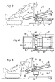
- the loading carriage 1 essentially consists of a chassis frame 3 supported on rail running gear 2, on which a conveyor belt arrangement 4 running in the longitudinal direction of the carriage is provided.
- Buffers 5 are provided at each longitudinal end of the chassis frame 3 and are arranged in a frame plane 6 formed by the chassis frame 3.
- One in the front is used for energy supply Motor 7 arranged in the end region of the carriage.
- the conveyor belt arrangement 4 is composed of a transfer conveyor belt 8 arranged in the transport direction in the front end region and displaceable in its longitudinal direction and a receiving conveyor belt 9 with a hopper 10 located in its lower end region.
- the transfer conveyor belt 8 is slidably mounted in its lower end region in a guide frame 11, which in turn is pivotally connected to the chassis frame 3 about an axis 12 running perpendicular to the conveying plane.
- a support frame 13 with support rollers 14 is provided in the front end region of the chassis frame 3, which are mounted on the support frame 13 so as to be displaceable transversely to the longitudinal direction of the carriage.
- the chassis frame 3 has an opening 16 in its end located in the area of the rear rail undercarriage 2 for the rail chassis 2 to pass through.
- This is mounted on the chassis frame 3 by means of two articulation rods 17, each arranged on a longitudinal side of the carriage and extending in the longitudinal direction of the carriage to the front rail chassis 2, about an axis 18 extending transversely to the longitudinal direction of the carriage, and connected to drives 19 for height adjustment.
- a rear buffer breast 20 connected to the buffers 5 is mounted on the chassis frame 3 so as to be pivotable about an axis running transversely to the longitudinal direction of the wagon, and is connected to pivoting drives 21.
- the buffer breast 20 is U-shaped with two frame parts 22 running in the longitudinal direction of the carriage and parallel to one another.
- the loading wagon 1 is moved to just before a track construction site, so that the bulk hopper 10 or the rear end of the conveyor belt arrangement 4 is already above the track construction site. Then the two drives 19 are subjected to a lowering of the rear section of the chassis frame 3 with respect to the rear rail chassis 2.
- the transfer conveyor belt 8 is shifted from the rear transfer position, which is partly shown in dash-dotted lines, into a rear transfer position shown in FIG. 1 and 2, transfer position shown with full lines, in which a discharge end 26 is located above the bulk goods loading wagon 23.
- the swivel drive 15 enables swiveling movements to be carried out in curved tracks, so that the discharge end 26 comes to lie exactly in the middle above the wagon to be loaded.
- This lower pick-up position for loading for example by an excavator 24 is shown in full lines in FIG.
- FIG. 5 shows a further loading carriage 27 with a chassis frame 28 and two rail carriages 29 (only the rear one of which is shown in the transport direction) and with a conveyor belt arrangement 35.
- a chassis frame 28 In its receiving end 31 located below a frame plane 30 formed by the chassis frame 28, this has a hopper 32.
- a rear, U-shaped buffer breast 33 is pivotally connected to the chassis frame 28 by means of pivot drives 34 about axes extending transversely to the longitudinal direction of the carriage.
- the section of the conveyor belt arrangement 35 located in the region of the hopper 32 is more inclined in the direction of the track 36 compared to the remaining section. This makes it possible to arrange the receiving end 31 relatively deep for simplified loading even without adjusting the height of the rear rail chassis 29 relative to the chassis frame 28.
Landscapes
- Engineering & Computer Science (AREA)
- Transportation (AREA)
- Mechanical Engineering (AREA)
- Architecture (AREA)
- Civil Engineering (AREA)
- Structural Engineering (AREA)
- Loading Or Unloading Of Vehicles (AREA)
- Machines For Laying And Maintaining Railways (AREA)
- Ship Loading And Unloading (AREA)
- Filling Or Emptying Of Bunkers, Hoppers, And Tanks (AREA)
- Mobile Radio Communication Systems (AREA)
- Inorganic Insulating Materials (AREA)
- Multiple-Way Valves (AREA)
- Load-Engaging Elements For Cranes (AREA)
- Framework For Endless Conveyors (AREA)
- Vertical, Hearth, Or Arc Furnaces (AREA)
Applications Claiming Priority (2)
| Application Number | Priority Date | Filing Date | Title |
|---|---|---|---|
| AT66391 | 1991-03-26 | ||
| AT663/91 | 1991-03-26 |
Publications (2)
| Publication Number | Publication Date |
|---|---|
| EP0505933A1 EP0505933A1 (de) | 1992-09-30 |
| EP0505933B1 true EP0505933B1 (de) | 1994-07-06 |
Family
ID=3496536
Family Applications (1)
| Application Number | Title | Priority Date | Filing Date |
|---|---|---|---|
| EP92104843A Expired - Lifetime EP0505933B1 (de) | 1991-03-26 | 1992-03-20 | Beladewagen zum Aufnehmen, Weitertransport und Abwurf von Schüttgut |
Country Status (10)
| Country | Link |
|---|---|
| US (1) | US5277538A (es) |
| EP (1) | EP0505933B1 (es) |
| AT (1) | ATE108234T1 (es) |
| AU (1) | AU639636B2 (es) |
| CZ (1) | CZ278669B6 (es) |
| DE (1) | DE59200263D1 (es) |
| ES (1) | ES2057939T3 (es) |
| HU (1) | HU208349B (es) |
| PL (1) | PL169747B1 (es) |
| SK (1) | SK279317B6 (es) |
Cited By (1)
| Publication number | Priority date | Publication date | Assignee | Title |
|---|---|---|---|---|
| EP2562308A2 (de) | 2011-08-26 | 2013-02-27 | Matisa Materiel Industriel S.A. | Verfahren und Transportanlage zum kontinuielichen Transport von Schüttgut. |
Families Citing this family (17)
| Publication number | Priority date | Publication date | Assignee | Title |
|---|---|---|---|---|
| DE59706089D1 (de) * | 1996-10-22 | 2002-02-28 | Plasser Bahnbaumasch Franz | Schüttgutverladewagen |
| DE59706953D1 (de) * | 1996-11-07 | 2002-05-16 | Plasser Bahnbaumasch Franz | Schüttgutverladewagen |
| ITMI20041909A1 (it) * | 2004-10-08 | 2005-01-08 | Cesare Rossanigo | Cassone di carri ferroviari da trasporto pietrisco e altro materiale particolarmente per risanatrici ferroviarie carro per risanatrici ferroviarie comprendente tale cassone e procedimento per realizzare detto carro |
| US20060225314A1 (en) * | 2005-04-06 | 2006-10-12 | Hill James T | Excavator |
| AT505187B1 (de) * | 2007-05-10 | 2009-01-15 | Plasser Bahnbaumasch Franz | Speicherwagen für schüttgut |
| DE102008003951A1 (de) * | 2008-01-11 | 2009-07-16 | Werner Stark | Vorrichtung zum Verbringen von Baustoffen für einen Unterbau und/oder Oberbau einer Fahrbahn |
| AT507672B1 (de) * | 2009-04-07 | 2010-07-15 | Plasser Bahnbaumasch Franz | Speicherwagen zum transport von schüttgut und verfahren |
| AT507788B1 (de) * | 2009-06-03 | 2010-08-15 | Plasser Bahnbaumasch Franz | Schotterpflug zum einschottern eines gleises |
| CN101718064B (zh) * | 2009-11-23 | 2012-06-27 | 株洲新通铁路装备有限公司 | 一种铁路钢轨扣件回收作业车及换轨扣件回收作业方法 |
| US20140183003A1 (en) * | 2012-12-31 | 2014-07-03 | Caterpillar Inc. | Cold Planer with Aligned Transition Zone |
| AT516471B1 (de) * | 2014-10-27 | 2017-02-15 | Hp3 Real Gmbh | Vorrichtung zur Materialförderung für den Gleisbau |
| US9346473B1 (en) | 2014-11-05 | 2016-05-24 | Herzog Railroad Services, Inc. | Material transport and distribution consist with controlled gated hopper cars and conveyor systems |
| US10399785B1 (en) | 2018-05-31 | 2019-09-03 | Stout Conveyors, LLC | Compact portable conveyor |
| US10589933B2 (en) | 2018-06-26 | 2020-03-17 | Caterpillar Paving Products Inc. | Flexible hopper for a conveyor system |
| US10583995B2 (en) * | 2018-06-26 | 2020-03-10 | Caterpillar Paving Products, Inc. | Flexible hopper for a conveyor system |
| CN108792503A (zh) * | 2018-06-30 | 2018-11-13 | 郭青华 | 一种瓶胚连线生产设备 |
| CN114084846B (zh) * | 2022-01-21 | 2022-04-29 | 山东金钟科技集团股份有限公司 | 一种举升式液压翻板装置 |
Family Cites Families (23)
| Publication number | Priority date | Publication date | Assignee | Title |
|---|---|---|---|---|
| US1458043A (en) * | 1921-11-26 | 1923-06-05 | Frank S Follansbee | Method of and apparatus for loading material |
| US2896771A (en) * | 1957-07-03 | 1959-07-28 | Sierra Engineering Co Inc | Portable concrete batcher |
| US3167193A (en) * | 1962-05-14 | 1965-01-26 | Klosk Lawrence | Loading car with conveyor |
| US3184038A (en) * | 1963-05-24 | 1965-05-18 | Petchuk Joseph | Material handling apparatus |
| US3343502A (en) * | 1964-01-29 | 1967-09-26 | Nolan Company | Convertible railway vehicle highway trailer |
| DE1658324A1 (de) * | 1967-08-21 | 1970-09-17 | Mini Verkehrswesen | Maschine zur Reinigung des Schotterbettes von Eisenbahngleisen |
| US3512669A (en) * | 1968-09-10 | 1970-05-19 | Clark Benedict Corp | Mobile transfer apparatus |
| US3687276A (en) * | 1971-01-04 | 1972-08-29 | Mechtron Intern Corp | Self-propelled conveyor apparatus |
| DD95026A1 (es) * | 1971-08-17 | 1973-01-12 | ||
| CH597428A5 (es) * | 1976-11-24 | 1978-04-14 | Scheuchzer Auguste Les Fils De | |
| AT361978B (de) * | 1979-07-20 | 1981-04-10 | Waagner Biro Ag | Wagen fuer eine fahrbahn mit stark unter- schiedlicher steigung |
| DE3312492A1 (de) * | 1982-09-23 | 1984-03-29 | Franz Plasser Bahnbaumaschinen-Industriegesellschaft mbH, 1010 Wien | Schuettgutverladewagen, insbesondere zur abraumverladung von einer schotterbett-reinigungsmaschine |
| US4534297A (en) * | 1982-12-02 | 1985-08-13 | Johnson Sr Theodore C | Wheel position control for railway maintenance vehicle |
| DE3420658C1 (de) * | 1984-06-02 | 1985-07-18 | Feluwa Schlesiger & Co KG, 5531 Mürlenbach | Vorrichtung zur Entwaesserung von Schlaemmen u.dgl.,insbesondere Untertagegeraet zur Entwaesserung von Bergeschlaemmen |
| ATE51910T1 (de) * | 1985-06-06 | 1990-04-15 | Edwin Desteiger Snead | Selbstentladerzug fuer sturzgueter. |
| US4925356A (en) * | 1985-06-06 | 1990-05-15 | Snead Edwin D | Self-unloading train for bulk commodities |
| DE3640916C2 (de) * | 1986-11-29 | 1998-07-16 | Stetter Gmbh | Verfahren und Einrichtung zur Betonherstellung in einem Tunnel |
| GB8803593D0 (en) * | 1988-02-17 | 1988-03-16 | Standard Railway Wagon | Freight discharge of railway wagons |
| US4919583A (en) * | 1988-10-03 | 1990-04-24 | Speakman Jr William J | Trailer |
| DE8908700U1 (es) * | 1988-11-05 | 1989-09-07 | Hermann Wiebe Grundstuecks- Und Maschinenanlagen Kg, 2800 Bremen, De | |
| DE8813858U1 (es) * | 1988-11-05 | 1988-12-22 | Hermann Wiebe Grundstuecks- Und Maschinenanlagen Kg, 2800 Bremen, De | |
| US5029532A (en) * | 1988-12-22 | 1991-07-09 | Snead Edwin De S | Control cab |
| US5131798A (en) * | 1990-12-28 | 1992-07-21 | Loram Maintenance Of Way, Inc. | Railroad car conveyor |
-
1992
- 1992-02-20 US US07/839,247 patent/US5277538A/en not_active Expired - Fee Related
- 1992-03-13 PL PL92293838A patent/PL169747B1/pl not_active IP Right Cessation
- 1992-03-20 AT AT92104843T patent/ATE108234T1/de not_active IP Right Cessation
- 1992-03-20 DE DE59200263T patent/DE59200263D1/de not_active Expired - Lifetime
- 1992-03-20 EP EP92104843A patent/EP0505933B1/de not_active Expired - Lifetime
- 1992-03-20 ES ES92104843T patent/ES2057939T3/es not_active Expired - Lifetime
- 1992-03-23 CZ CS92870A patent/CZ278669B6/cs not_active IP Right Cessation
- 1992-03-23 SK SK870-92A patent/SK279317B6/sk not_active IP Right Cessation
- 1992-03-24 HU HU9200971A patent/HU208349B/hu not_active IP Right Cessation
- 1992-03-25 AU AU13177/92A patent/AU639636B2/en not_active Ceased
Cited By (2)
| Publication number | Priority date | Publication date | Assignee | Title |
|---|---|---|---|---|
| EP2562308A2 (de) | 2011-08-26 | 2013-02-27 | Matisa Materiel Industriel S.A. | Verfahren und Transportanlage zum kontinuielichen Transport von Schüttgut. |
| EP2562308A3 (de) * | 2011-08-26 | 2015-01-07 | Matisa Materiel Industriel S.A. | Verfahren und Transportanlage zum kontinuielichen Transport von Schüttgut. |
Also Published As
| Publication number | Publication date |
|---|---|
| SK279317B6 (sk) | 1998-09-09 |
| ES2057939T3 (es) | 1994-10-16 |
| HUT61059A (en) | 1992-11-30 |
| CZ278669B6 (en) | 1994-04-13 |
| PL293838A1 (en) | 1992-11-30 |
| US5277538A (en) | 1994-01-11 |
| ATE108234T1 (de) | 1994-07-15 |
| DE59200263D1 (de) | 1994-08-11 |
| HU9200971D0 (en) | 1992-06-29 |
| EP0505933A1 (de) | 1992-09-30 |
| AU639636B2 (en) | 1993-07-29 |
| HU208349B (en) | 1993-09-28 |
| PL169747B1 (pl) | 1996-08-30 |
| CS87092A3 (en) | 1992-10-14 |
| AU1317792A (en) | 1992-10-01 |
Similar Documents
| Publication | Publication Date | Title |
|---|---|---|
| EP0505933B1 (de) | Beladewagen zum Aufnehmen, Weitertransport und Abwurf von Schüttgut | |
| EP0426004B1 (de) | Maschine zum Aufnehmen und Verteilen des Bettungsschotters | |
| EP0838383B1 (de) | Schüttgutverladewagen | |
| EP0599799B1 (de) | Verladewagen zum Transport von Schüttgut | |
| DE3711707A1 (de) | Gleisverfahrbarer schuettgutverladewagen mit regelbaren entladeschurren | |
| EP0490868B1 (de) | Verladewagen für Schüttgut | |
| EP0501318A1 (de) | Transportwagen | |
| DE3228015A1 (de) | Gleisverfahrbare anlage zum transport von schuettgut | |
| CH615969A5 (en) | Movable machine arrangement for transporting bulk material | |
| EP0096236B1 (de) | Schienengängiger Transportwaggon, Transportzug und Verfahren zur Aufnahme und Abgabe von Gleisbaumaterial | |
| DE1219399B (de) | Einrichtung zum Aufnehmen und Abfoerdern von Schuettgut von einem Lagerplatz | |
| DE3318992C2 (es) | ||
| DE3151030C2 (es) | ||
| DE4104877C2 (de) | Schüttgutverladewagen | |
| DE3136316C2 (de) | Entladevorrichtung, insbesondere zur Aufnahme von Schüttgut aus Waggons od. dgl. | |
| DE3430642A1 (de) | Verfahrbarer schraegaufzug | |
| DE4213925C2 (de) | Wagenzug zum Speichern und für den Transport von Schüttgut | |
| DE3532182C2 (es) | ||
| AT504497B1 (de) | Speicherwagen | |
| EP1881110B1 (de) | Vorrichtung und Verfahren für den Ausbau eines aus Gleisfeldern bzw. Gleisjochen gebildeten Gleises | |
| DE3725595C2 (es) | ||
| AT404947B (de) | Wagen zur einschotterung eines gleises | |
| DE3247743C1 (de) | Verfahrbarer Schaufelradbagger | |
| DE3303059A1 (de) | Verbindungsfoerderer | |
| AT370799B (de) | Fahrbare anlage zur gleisunterbau-sanierung |
Legal Events
| Date | Code | Title | Description |
|---|---|---|---|
| PUAI | Public reference made under article 153(3) epc to a published international application that has entered the european phase |
Free format text: ORIGINAL CODE: 0009012 |
|
| 17P | Request for examination filed |
Effective date: 19920803 |
|
| AK | Designated contracting states |
Kind code of ref document: A1 Designated state(s): AT DE ES FR GB IT NL SE |
|
| 17Q | First examination report despatched |
Effective date: 19931216 |
|
| GRAA | (expected) grant |
Free format text: ORIGINAL CODE: 0009210 |
|
| AK | Designated contracting states |
Kind code of ref document: B1 Designated state(s): AT DE ES FR GB IT NL SE |
|
| REF | Corresponds to: |
Ref document number: 108234 Country of ref document: AT Date of ref document: 19940715 Kind code of ref document: T |
|
| REF | Corresponds to: |
Ref document number: 59200263 Country of ref document: DE Date of ref document: 19940811 |
|
| GBT | Gb: translation of ep patent filed (gb section 77(6)(a)/1977) |
Effective date: 19940714 |
|
| ITF | It: translation for a ep patent filed |
Owner name: ING. A. GIAMBROCONO & C. S.R.L. |
|
| ET | Fr: translation filed | ||
| REG | Reference to a national code |
Ref country code: ES Ref legal event code: FG2A Ref document number: 2057939 Country of ref document: ES Kind code of ref document: T3 |
|
| EAL | Se: european patent in force in sweden |
Ref document number: 92104843.5 |
|
| PLBE | No opposition filed within time limit |
Free format text: ORIGINAL CODE: 0009261 |
|
| STAA | Information on the status of an ep patent application or granted ep patent |
Free format text: STATUS: NO OPPOSITION FILED WITHIN TIME LIMIT |
|
| 26N | No opposition filed | ||
| REG | Reference to a national code |
Ref country code: GB Ref legal event code: IF02 |
|
| PGFP | Annual fee paid to national office [announced via postgrant information from national office to epo] |
Ref country code: FR Payment date: 20100331 Year of fee payment: 19 |
|
| PGFP | Annual fee paid to national office [announced via postgrant information from national office to epo] |
Ref country code: GB Payment date: 20100302 Year of fee payment: 19 Ref country code: AT Payment date: 20100209 Year of fee payment: 19 |
|
| PGFP | Annual fee paid to national office [announced via postgrant information from national office to epo] |
Ref country code: ES Payment date: 20100317 Year of fee payment: 19 |
|
| PGFP | Annual fee paid to national office [announced via postgrant information from national office to epo] |
Ref country code: DE Payment date: 20100521 Year of fee payment: 19 Ref country code: NL Payment date: 20100322 Year of fee payment: 19 Ref country code: IT Payment date: 20100327 Year of fee payment: 19 |
|
| PGFP | Annual fee paid to national office [announced via postgrant information from national office to epo] |
Ref country code: SE Payment date: 20100322 Year of fee payment: 19 |
|
| REG | Reference to a national code |
Ref country code: NL Ref legal event code: V1 Effective date: 20111001 |
|
| REG | Reference to a national code |
Ref country code: SE Ref legal event code: EUG |
|
| GBPC | Gb: european patent ceased through non-payment of renewal fee |
Effective date: 20110320 |
|
| PG25 | Lapsed in a contracting state [announced via postgrant information from national office to epo] |
Ref country code: AT Free format text: LAPSE BECAUSE OF NON-PAYMENT OF DUE FEES Effective date: 20110320 |
|
| REG | Reference to a national code |
Ref country code: FR Ref legal event code: ST Effective date: 20111130 |
|
| PG25 | Lapsed in a contracting state [announced via postgrant information from national office to epo] |
Ref country code: NL Free format text: LAPSE BECAUSE OF NON-PAYMENT OF DUE FEES Effective date: 20111001 Ref country code: FR Free format text: LAPSE BECAUSE OF NON-PAYMENT OF DUE FEES Effective date: 20110331 Ref country code: DE Free format text: LAPSE BECAUSE OF NON-PAYMENT OF DUE FEES Effective date: 20111001 |
|
| REG | Reference to a national code |
Ref country code: DE Ref legal event code: R119 Ref document number: 59200263 Country of ref document: DE Effective date: 20111001 |
|
| PG25 | Lapsed in a contracting state [announced via postgrant information from national office to epo] |
Ref country code: GB Free format text: LAPSE BECAUSE OF NON-PAYMENT OF DUE FEES Effective date: 20110320 Ref country code: IT Free format text: LAPSE BECAUSE OF NON-PAYMENT OF DUE FEES Effective date: 20110320 |
|
| REG | Reference to a national code |
Ref country code: ES Ref legal event code: FD2A Effective date: 20120423 |
|
| PG25 | Lapsed in a contracting state [announced via postgrant information from national office to epo] |
Ref country code: ES Free format text: LAPSE BECAUSE OF NON-PAYMENT OF DUE FEES Effective date: 20110321 |
|
| PG25 | Lapsed in a contracting state [announced via postgrant information from national office to epo] |
Ref country code: SE Free format text: LAPSE BECAUSE OF NON-PAYMENT OF DUE FEES Effective date: 20110321 |