EP0423820A2 - Imprimante à jet d'encre - Google Patents
Imprimante à jet d'encre Download PDFInfo
- Publication number
- EP0423820A2 EP0423820A2 EP90120108A EP90120108A EP0423820A2 EP 0423820 A2 EP0423820 A2 EP 0423820A2 EP 90120108 A EP90120108 A EP 90120108A EP 90120108 A EP90120108 A EP 90120108A EP 0423820 A2 EP0423820 A2 EP 0423820A2
- Authority
- EP
- European Patent Office
- Prior art keywords
- sheet
- recording
- recording medium
- ink jet
- jet printer
- Prior art date
- Legal status (The legal status is an assumption and is not a legal conclusion. Google has not performed a legal analysis and makes no representation as to the accuracy of the status listed.)
- Granted
Links
Images


Classifications
-
- B—PERFORMING OPERATIONS; TRANSPORTING
- B41—PRINTING; LINING MACHINES; TYPEWRITERS; STAMPS
- B41J—TYPEWRITERS; SELECTIVE PRINTING MECHANISMS, i.e. MECHANISMS PRINTING OTHERWISE THAN FROM A FORME; CORRECTION OF TYPOGRAPHICAL ERRORS
- B41J11/00—Devices or arrangements of selective printing mechanisms, e.g. ink-jet printers or thermal printers, for supporting or handling copy material in sheet or web form
- B41J11/0015—Devices or arrangements of selective printing mechanisms, e.g. ink-jet printers or thermal printers, for supporting or handling copy material in sheet or web form for treating before, during or after printing or for uniform coating or laminating the copy material before or after printing
- B41J11/002—Curing or drying the ink on the copy materials, e.g. by heating or irradiating
- B41J11/0022—Curing or drying the ink on the copy materials, e.g. by heating or irradiating using convection means, e.g. by using a fan for blowing or sucking air
Definitions
- the present invention relates to an ink jet printer in which ink is jetted selectively from a number of nozzles.
- An ink jet printer for jetting ink from a selected one or plural nozzles to record characters, patterns, etc., on a recording sheet is advantageous in that it makes no noise while in operation and it can record data on an ordinary recording sheet at low operating cost.
- an ink jet printer of this type uses water-soluble ink in order to stabilize the writing operation.
- the printer may suffer from the difficulty that the water contained in the water-soluble ink may make the recording sheet wavy or swell it during a printing operation, as a result of which it becomes rather difficult to convey the recording sheet to the following work position.
- Japanese Unexamined Published Patent Application No. 156536/1979 has disclosed a device in which hot air is blown against the recording sheet on the platen to dry the ink.
- U.S. Patent No. 4,340,893 has disclosed a device in which hot air is blown against the recording sheet directly through the carriage to dry the ink on the recording sheet as soon as data is recorded on it.
- those conventional devices are still disadvantageous in that, in general, characters or patterns recorded on a recording sheet often vary in density, and sometimes they may be solid black. Hence, even if a hot air dryer is set downstream of the recording section to dry the recording sheet, it is rather difficult to sufficiently dry parts of the recording sheet having a high pixel density.
- wet parts of the recording sheet may be brought into contact with the back side of the following recording sheet, thus spoiling the recorded image.
- parts of the recording sheet swelled and buckled by the ink may be brought into contact with the printing head, thus wearing the latter.
- an object of this invention is to provide an ink jet printer in which, even when an image to be printed includes a part having a relatively high density requiring a relatively large quantity of ink, the recording medium is uniformly dried in its entirety.
- an ink jet printer in which the speed of conveyance of the recording medium is controlled according to the image density.
- the invention also provides an ink jet printer in which the distance between the recording medium and the recording head is maintained constant to eliminate the difficulty of a printed image being spoiled by contact of the head with the recording medium, whereby the resultant image is maintained high in accuracy.
- a pair of sheet retaining means are provided before and behind in the direction of travel of recording means, and the one of the pair of sheet retaining means which is located before in the direction of travel is allowed to push the recording medium against the platen to form a gap between the recording medium and the printing head.
- the invention also provides an ink jet printer in which the recording medium is conveyed with the recorded image unaffected.
- cylindrical rollers relatively small in wall thickness and plate-shaped rollers with peripheral teeth are provided downstream of the recording means and mounted in such a manner that the rollers are confronted with each other.
- Fig. 1 shows a typical example of an ink jet printer constructed according to the invention
- Fig. 2 shows essential components of the printer of Fig. 1 in detail.
- the ink jet printer of Fig. 1 includes a recording sheet conveying mechanism extended between a sheet supplying section and a sheet discharging section 60, a printing head 82 disposed along the sheet conveying path, and a hot air drying unit 90.
- a sheet supplying stand 12 is disposed in the sheet supplying section 10.
- the sheet supplying stand is urged upwardly by a hopper spring 11 in such a manner that it is movable vertically, whereby the top of the recording sheet S stacked on the sheet supplying stand 12 is held in abutment zo with a sheet supplying roller 13.
- a sheet conveying guide board 14 extends from the sheet supplying roller 13 to a gate roller 21.
- a separating pawl operating lever 17, which is operated up and down by a manual operating lever (not shown), and a separating pawl 16, which is operated by the lever 17, are arranged on the guide board 14.
- a web inserting guide board 19 is provided above the sheet supplying stand 12 confronting the sheet supplying opening 3 formed in the front board 2 of a printer body 1 (Fig. 10), so that the recording sheet on the web is directly fed into the gate roller 21 with the aid of a tractor 15.
- the guide board 19 is followed by a sheet conveying section 20.
- the gate roller 21 engaged with a drive force transmitting mechanism (not shown) is arranged beside a carriage 80 on the upstream side of the travel path of the latter.
- the gate roller 21 is designed so that it performs an intermittent feed operation at a speed corresponding to the pixel density of a character or pattern recorded on the recording sheet S.
- a driven roller 22 is provided behind a platen 46, and a sheet conveying belt 23 is laid over the driven roller 22 and the gate roller 21.
- the gate roller 21 rotates the driven roller 22 through the sheet conveying belt 23 at the same peripheral speed.
- the sheet feed belt 23 contacts an idler 25 directly below the platen 46.
- the idler 25 is supported on one end portion of an idler lever 26.
- a tension spring 27 is connected to the idler lever 26 so as to apply a predetermined tension to the sheet conveying belt 23.
- a sheet retaining roller lever 29 is supported above the gate roller 21 in such a manner that it is swingable about a fulcrum 31.
- the sheet retaining roller lever 29 is designed so as to change the contact pressure between the sheet conveying belt 23 and a sheet retaining roller 32 separately according to the kinds of recording media to be conveyed, i.e., according to whether the recording medium is conveyed by the frictional force produced between the sheet conveying belt 23 and the sheet conveying roller 32, as in the case of a recording sheet or envelop, or whether the recording medium is conveyed by the tractor 15, as in the case of a web.
- a strong retaining spring 33 is connected to one end of the upper arm 29a of the sheet retaining roller lever 29 to turn the lever 29 counterclockwise in Fig. 1, while a cam 34 is engaged with the upper arm 29a to turn the lever 29 clockwise in Fig. 1 against the elastic force of the spring 33.
- the cam 34 When, as indicated by the solid lines, the cam 34 is released to cause the strong spring 33 to act directly on the lever 29, the sheet retaining roller 32, positioned in an arcuate groove 30 formed in the lower arm 29b of the lever 29, is strongly pushed against the sheet conveying belt 23.
- the cam 34 lowers the lever 29 to release the strong spring 33, the sheet retaining roller 32 is weakly pushed against the sheet conveying belt 23 by one end portion 35 of a weak coil spring 35a, the other end of which is connected to the sheet retaining roller lever 29.
- a paper bail 37 provided above the driven roller 22 is moved into or out of engagement with the sheet conveying belt 23.
- the paper bail 37 is composed of a shaft 36 and a plurality of plate-shaped rollers with peripheral teeth, which are fixedly mounted on the shaft 36.
- the paper bail 37 is supported on one end portion of a paper bail lever 38, which is secured to a supporting shaft 39 provided downstream of the driven roller 22.
- a sector gear 40 engaged with a pinion 41 is secured to the supporting shaft 39.
- the sector gear 40 is turned clockwise in Fig. 3, immediately before the recording sheet S passes through the gate roller 21, to push the paper bail 37 (supported by the end of the paper bail lever 38) against the sheet conveying belt 23 thereby to convey the recording sheet S.
- a recording sheet carry-in side guide board 43 is provided upstream of the platen 46.
- the start edge of the guide board 43 coterminous with the meeting point of the web inserting guide board 19 and the sheet conveying guide board 14 extended from the sheet supplying roller 13, and the end edge is located immediately before the printing section connected to the platen 46.
- a sheet retaining board 45 is held abutted against the guide board 43 by its own elasticity.
- the platen 46 is disposed directly below the travel path of the carriage 80.
- the base end of the platen 46 is secured to a fulcrum shaft 47 provided downstream of the platen 46.
- the platen 46 is lowered, or retracted, to the position indicated by the two-dot chain line in Fig. 2 by a lever (not shown) coupled through a link to the manual operating lever adapted to operate the separating pawl operating lever 17, thereby to allow the passage of a recording medium such as an envelope relatively large in thickness.
- a pair of intermediate sheet discharging roller shafts 62 and 65 are arranged downstream of the driven roller 22 in such a manner that they are adjacent to the driven roller 22.
- the intermediate sheet discharging roller shaft 62 is located below the other intermediate sheet discharging roller shaft 65 and below a sheet discharging guide board 61.
- a plurality of short intermediate sheet discharging rollers 63 made of an elastic material are fixedly mounted on the shaft 62 spaced from one another.
- Each of the rollers 63 has cylindrical rollers 64 and 64 having a small wall thickness at both ends.
- the upper intermediate sheet discharging roller shaft 65 on the side of the head. 82 has a plurality of thin-plate-shaped toothed rollers 66.
- the toothed rollers 66 are mounted on the roller shaft 65 in such a manner as to confront with the cylindrical rollers 64 of the intermediate sheet discharging rollers 63 so that they, together with the cylindrical rollers 64, gently nip the wet recording sheet S to discharge it.
- the intermediate sheet discharging rollers 63 and 66 may be designed as shown in Fig. 5a.
- a plurality of intermediate sheet discharging rollers 63 are mounted on the lower intermediate sheet discharging roller shaft 62 spaced from one other another, and the cylindrical rollers 64 of adjacent ones of the sheet discharging rollers 63 are confronted with each other.
- a plurality of thin-plate-shaped toothed rollers 66 are mounted on the upper roller shaft 65, which is located on the side of the head 82, in such a manner that each toothed roller 66 is located between the adjacent cylindrical rollers 64 and 64 extending slightly into the space between the cylindrical rollers 64 and 64. This eliminate the difficulty of, in the conveyance of the recording sheet, ink on the teeth of the toothed rollers 66 sticking to the intermediate sheet discharging rollers 63 and thus staining the back side of the recording sheet S.
- a pair of sheet discharging roller shafts 68 and 71 are provided downstream of the hot air drying unit 90 (described later in detail).
- the upper shaft discharging roller shaft 68 is disposed below the sheet discharging board 61.
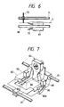
- a plurality of sheet discharging rollers 69 made of an elastic material are fixedly mounted on the upper sheet discharging roller shaft 68.
- Each of the sheet discharging rollers 69, as shown in Fig. 6, has a cylindrical roller 70 only at one end thereof.
- the upper sheet discharging roller shaft 71 on the side of the head 82 has a plurality of thin-plate-shaped toothed rollers 72.
- the toothed rollers 72 are mounted on the roller shaft 71 in such a manner that they are spaced from the cylindrical rollers 70 and are slightly overlapped with the latter as viewed in the axial direction. These rollers 69 and 72 strongly wave the dried recording sheet S in the direction of conveyance so that the recording sheet S is delivered flat onto a sheet discharging tray 74 while being stiffened.
- the carriage 80 is moved while being guided by two guide rails 81 and 81 which are laid perpendicular to the recording sheet conveyance direction.
- the carriage 80 is provided with the ink jet head 82, which jets ink through at least one nozzle onto the recording sheet S.
- a pair of solenoids 88 and 88 are provided on both sides of the carriage 80.
- a pair of sheet retaining levers 86 and 86 which are driven by respective ones of the solenoids 88 and 88, are swingably supported on both sides of the lower surface of the carriage 80 in such a manner that the end portion 82a of the head 82 is positioned between them.
- the end portions 86a of the sheet retaining levers 86 are alternately moved up an down, as indicated in Fig.
- rollers 87 may be coupled to the end portions 86a of the sheet retaining levers 86 so that the end portions 86a of the sheet retaining levers 86 can push the recording sheet S against the platen 46 while smoothly moving on the recording sheet S.
- an integral-duct type fan 83 with an inverted-V-shaped air blowing outlet is provided downstream of the carriage 80 in the sheet conveyance direction.
- the fan 83 designed so that, as shown in Figs. 9a and 9b, air streams are applied to the recording sheet S while being deflected right and left by a baffle plate 84 set vertically on one side of the carriage 80, and then directed to the other side, thus blowing dust, paper powder or the like off the recording sheet.
- an upward movement regulating piece 89 is mounted upstream of and below the carriage 80 in such a manner that it forms a small gap with the end of a retaining board 45.
- the regulating piece 89 prevents the retaining board 45 from being moved upwardly.
- the hot air drying unit 90 operates to dry the recording sheet S, on which data have been recorded, by applying hot air to it.
- the drying unit 90 is mounted on two side boards 4 and 4 of the printer body 1.
- the drying unit 90 includes a duct 91 confronting a sheet discharging guide board 61 (Fig. 2), a heater 93 accommodated in the duct 91, and a fan 94 (Fig. 11) installed at a suitable location in the printer body 1. Air which is introduced into the duct 91 through an air pipe 96 from the fan 94 is heated by the heater 93, and the air thus heated is directed against the recording sheet through a number of small air blowing holes 92 formed in the lower board of the duct 91 and directed in the sheet conveyance direction.
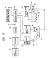
- a control circuit for the printer is arranged as shown in Fig. 11.
- a host computer 50 provides recording data for one page, for instance, to be printed.
- the recording data are applied through an interface 51 to a buffer 52 so as to be stored in the latter 52.
- a control means 53 applies control signals to a sheet conveyance drive means 55, a head drive means 56, and a heater drive means 57, so that a drive motor 58, the printing head 82, and a heater 93 and a fan motor 95 perform sheet conveyance, a recording operation, and a recording sheet drying operation, respectively.
- the recording data stored in the buffer 52 are applied to a printing pattern analyzing means 54.
- the latter 54 determines from the input recording data the quantity of ink, or the number of dots, for printing each of several regions 1′ through 6′, as shown in Fig. 12, defined along a printing line. More specifically, the printing pattern analyzing circuit 54 detects the region having the largest number of dots in each line, i.e., the region having the largest pixel density in each line (in the case of Fig. 12, the fourth region, indicated by shading) and, for every line, applies the number of dots together with the region, as data, to the control means 53.
- a print drying table indicating relationships between quantities of ink per unitary area and corresponding ink drying time periods, as shown in Fig.
- the control means 53 determines an ink drying time period (Dx). In this manner, ink drying time periods (Dx) for all lines are obtained. These ink drying time periods (Dx) are added successively to determine estimated ink drying completion time instants (Tx) for all the lines.
- the ink drying time periods (Dx) and the estimated ink drying completion time instants (Tx) are written, as a drying control table, in a RAM (not shown) as indicated in Fig. 14.
- the control means 53 calculates an estimated drying completion time instant, and compares the time instant thus calculated with the present time instant, thereby to control the drive motor 58 to intermittently convey the recording sheet S.
- the separating pawl operating lever 17 is positioned as shown in Fig. 1 with a manual operating lever (not shown), so that the separating pawl 16 is abutted against the front end of the top one of the recording sheets S stacked on the sheet supplying stand 12.
- the lever (not shown) coupled to the manual operating lever lifts the platen 46 until the latter 46 becomes flush with the sheet conveyance guide board 43, and turns the cam 34 to the position indicated by the solid line in Fig. 2 to release the sheet retaining roller lever 29.
- the strong spring 33 acts on the sheet retaining roller lever 29 to strongly push the sheet retaining roller 32 coupled to the latter 29 against the sheet conveying belt 23.
- the sheet supplying roller 13 When, under this condition, the sheet supplying roller 13 is rotated, the top one of the recording sheets S stacked on the sheet supplying stand 12 is separated from the remaining sheets with the separating pawl 16, and moved along the sheet conveyance guide board 14 and the sheet conveyance guide board 43 to the gate roller 21. Since the gate roller 21 is strongly pushed against the sheet retaining roller 32 through the sheet conveying belt 23, the recording sheet S is conveyed to the printing section.
- the carriage 80 starts traveling along two guide rails 81 and 81, while the sheet retaining lever 86 located forwardly in the direction of travel of the carriage is turned by the solenoid 88 so that its end portion 86a pushes the recording sheet S against the platen 46. That is, the front end portion of the recording sheet S is pushed by the sheet retaining lever 86 to form a predetermined clearance between the recording sheet S and the printing head 82. Under this condition, characters, patterns, etc., are recorded on the recording sheet according to the inputted recording data.
- the integral-duct type fan 83 on the carriage 80 operates to blow air against the recording sheet S through the inverted-V-shaped air blowing outlet to form air streams which are directed from one side to the other wile being deflected right and left, thus blowing dust, paper powder or the like off the recording sheet in order to prevent the sticking of such foreign matter to the nozzle.
- the paper bail lever 38 is turned upwardly by the pinion 41 engaged with the sector 40, so that the paper bail 37 coupled to the end of the paper bail lever 38 is spaced away from the sheet conveying belt 23. That is, the recording sheet S on which dot image has been recorded is moved under the paper bail 37. Hence, the recording sheet S is delivered to the sheet discharging section 60 without spoiling the dot image.
- the thin toothed rollers 66 arranged immediately after the driven roller 22 are rotated while in contact with the cylindrical rollers 64 of the intermediate sheet discharging rollers 13.
- the recording sheet S wetted through the data writing operation is delivered into the hot air drying unit 90 while being in contact with the teeth of the thin toothed rollers 66 in a dotted form and being gently held between the toothed rollers 66 and the cylindrical rollers 64 of the intermediate sheet discharging rollers 13. Therefore, in this operation, the dot image on the recording sheet S is not spoiled at all.
- the hot air drying section 90 the recording sheet S is dried with hot air as required.
- the recording sheet S thus processed is delivered into the sheet discharging tray 74 by the sheet discharging rollers 69 and 72.
- a sheet edge detecting sensor (not shown) detects the rear edge to output a detection signal.
- the pinion 41 is rotated to swing the paper bail lever 38 downwardly through the sector 40.
- the paper bail 37 at the end of the paper bail lever 38 is pushed against the sheet conveying belt 23, thus holding the recording sheet S.
- the recording sheet S released from the gate roller 21 is forwarded to the hot air drying unit 90 with the recorded image maintained unaffected.
- the printing pattern analyzing means 54 receiving data to be recorded from the buffer 52, detects this phenomenon in advance, detects the region having the largest number of dots in every line, and applies numerical data indicative of the regions and the numbers of dots to the control means 53.
- the control means 53 referring to the relationships between quantities of ink per unitary area and corresponding ink drying time periods stored in advance, forms a drying control table (as shown in Fig.
- the drive motor 58 is operated, and if not, the drive motor 58 is held in a standby state. That is, the drive motor 58 is operated intermittently at intervals corresponding to the printing densities of those regions in the lines.
- the separating pawl operating lever 17 is operated with the manual operating lever to disengage the separating pawl 16 from the envelopes, and the platen 46 is retracted to the position indicated by the two-dot chain line in Fig. 2 with a lever which is operated in association with the manual operating lever.
- the envelope taken out of the stack with the sheet supplying roller 13 is delivered to the gate roller 21 while being guided by the slope 14a provided before the sheet conveying board 14, and then conveyed into the printing section while being strongly nipped by the sheet retaining roller 32 and the sheet conveying belt 23.
- the envelope is placed on the retracted platen, whereupon the sealing flap of the envelope is smoothly passed through the clearance over the platen 46, so that, similarly as in the case of the recording sheet, necessary data are recorded thereon.
Applications Claiming Priority (8)
| Application Number | Priority Date | Filing Date | Title |
|---|---|---|---|
| JP273273/89 | 1989-10-19 | ||
| JP27327389A JP2861124B2 (ja) | 1989-10-19 | 1989-10-19 | インクジェットプリンタの記録紙搬送処理装置 |
| JP31317589A JPH03173647A (ja) | 1989-12-01 | 1989-12-01 | インクジェット方式のプリンタ装置 |
| JP313175/89 | 1989-12-01 | ||
| JP14677190A JP2924096B2 (ja) | 1990-06-05 | 1990-06-05 | インクジェットプリンタ |
| JP146771/90 | 1990-06-05 | ||
| JP233807/90 | 1990-09-04 | ||
| JP23380790A JP2876748B2 (ja) | 1990-09-04 | 1990-09-04 | プリンタの記録紙搬送装置 |
Publications (3)
| Publication Number | Publication Date |
|---|---|
| EP0423820A2 true EP0423820A2 (fr) | 1991-04-24 |
| EP0423820A3 EP0423820A3 (en) | 1992-06-03 |
| EP0423820B1 EP0423820B1 (fr) | 1996-01-31 |
Family
ID=27472735
Family Applications (1)
| Application Number | Title | Priority Date | Filing Date |
|---|---|---|---|
| EP90120108A Expired - Lifetime EP0423820B1 (fr) | 1989-10-19 | 1990-10-19 | Imprimante à jet d'encre |
Country Status (4)
| Country | Link |
|---|---|
| US (4) | US5373312A (fr) |
| EP (1) | EP0423820B1 (fr) |
| DE (1) | DE69025124T2 (fr) |
| HK (1) | HK196396A (fr) |
Cited By (11)
| Publication number | Priority date | Publication date | Assignee | Title |
|---|---|---|---|---|
| DE4118645A1 (de) * | 1990-07-19 | 1992-01-23 | Mannesmann Ag | Tintendruckeinrichtung mit einer in abhaengigkeit von einer lokalen tintentroepfchenanhaeufung gesteuerten tintentrocknungseinrichtung |
| EP0622204A2 (fr) * | 1993-04-30 | 1994-11-02 | Hewlett-Packard Company | Commande auto-ajustable pour l'impression de la seconde page afin de réduire le maculage dans une imprimante par jet d'encre |
| EP0622203A2 (fr) * | 1993-04-30 | 1994-11-02 | Hewlett-Packard Company | Densimètre pour une commande adaptive du temps de séchage de l'encre pour une imprimante à jet d'encre |
| EP0720914A2 (fr) * | 1995-01-03 | 1996-07-10 | Xerox Corporation | Méthode pour optimiser la vitesse d'impression dans une imprimante par jet d'encre |
| WO1998019864A1 (fr) * | 1996-11-04 | 1998-05-14 | Spectra, Inc. | Imprimante a jet d'encre a passe simple |
| US5784090A (en) * | 1993-04-30 | 1998-07-21 | Hewlett-Packard Company | Use of densitometer for adaptive control of printer heater output to optimize drying time for different print media |
| EP0861730A3 (fr) * | 1997-02-26 | 1999-06-09 | Lexmark International, Inc. | Procédé de fabrication d'une tête d'impression pour imprimante à jet d'encre et procédé d'impression en faisant usage |
| NL1011065C2 (nl) * | 1999-01-19 | 2000-07-20 | Stork Digital Imaging Bv | Drukkop met luchtafzuiging. |
| US6308626B1 (en) * | 1999-02-17 | 2001-10-30 | Macdermid Acumen, Inc. | Convertible media dryer for a large format ink jet print engine |
| EP2228222A1 (fr) | 2009-03-09 | 2010-09-15 | FUJIFILM Corporation | Dispositif de formation d'images |
| WO2017219258A1 (fr) * | 2016-06-22 | 2017-12-28 | Hewlett-Packard Development Company, L.P. | Duplexage automatique modulé par la densité |
Families Citing this family (59)
| Publication number | Priority date | Publication date | Assignee | Title |
|---|---|---|---|---|
| US6619795B1 (en) * | 1993-11-10 | 2003-09-16 | Canon Kabushiki Kaisha | Ink jet recording apparatus |
| JP3313955B2 (ja) | 1994-12-09 | 2002-08-12 | キヤノン株式会社 | 画像形成装置 |
| US5579693A (en) * | 1994-12-12 | 1996-12-03 | Xerox Corporation | Curl control of printed sheets |
| US5838354A (en) * | 1995-05-31 | 1998-11-17 | Olympus Optical Co., Ltd. | Image forming apparatus |
| JPH0976591A (ja) * | 1995-09-19 | 1997-03-25 | Seiko Epson Corp | インクジェット記録方法 |
| US6161973A (en) * | 1996-01-22 | 2000-12-19 | Copyer Co., Ltd. | Ink-jet image forming device |
| US6203153B1 (en) | 1996-02-28 | 2001-03-20 | Hewlett-Packard Company | Method and apparatus for printing on gelatin coated media |
| JPH1016350A (ja) * | 1996-03-14 | 1998-01-20 | Canon Inc | プリント装置 |
| JPH09263341A (ja) * | 1996-03-26 | 1997-10-07 | Canon Inc | 印刷装置、印刷方法及び印刷システム |
| US5685538A (en) * | 1996-05-23 | 1997-11-11 | Xerox Corporation | Sheet registration around turn |
| JP3372800B2 (ja) * | 1996-12-06 | 2003-02-04 | キヤノン株式会社 | 記録装置 |
| US5844584A (en) * | 1996-12-31 | 1998-12-01 | Pitney Bowes Inc. | Print head stop mechanism for a postage meter |
| US6189993B1 (en) * | 1997-03-31 | 2001-02-20 | Xerox Corporation | Ink jet printer having multiple level grayscale printing |
| US6309064B1 (en) | 1997-11-20 | 2001-10-30 | Canon Kabushiki Kaisha | Printing apparatus |
| US6089773A (en) * | 1997-12-12 | 2000-07-18 | Lexmark International, Inc. | Print media feed system for an ink jet printer |
| US6139140A (en) * | 1998-09-29 | 2000-10-31 | Hewlett-Packard Company | Inkjet printing apparatus with media handling system providing small bottom margin capability |
| US6523949B1 (en) * | 1999-03-09 | 2003-02-25 | Brian C. Ewert | Variable image printing using inkjet printer |
| EP1101622B1 (fr) * | 1999-11-17 | 2006-03-01 | Canon Kabushiki Kaisha | Dispositif d'impression et procédé pour diminuer la charge de l'alimentation de puissance pour le dispositif d'impression |
| US6523948B2 (en) * | 2000-04-27 | 2003-02-25 | Fuji Photo Film Co., Ltd. | Ink jet printer and ink jet printing method |
| AU2005203477B2 (en) * | 2000-09-13 | 2005-10-06 | Zamtec Limited | Modular printer with ink drying means for print media |
| US6971811B2 (en) * | 2002-07-25 | 2005-12-06 | Silverbrook Research Pty Ltd | Print engine having a pair of feed rollers and a print zone proximal thereto |
| US7201523B2 (en) * | 2003-08-08 | 2007-04-10 | Silverbrook Research Pty Ltd | Print engine for a pagewidth inkjet printer |
| US6612240B1 (en) | 2000-09-15 | 2003-09-02 | Silverbrook Research Pty Ltd | Drying of an image on print media in a modular commercial printer |
| US6554414B2 (en) | 2001-01-02 | 2003-04-29 | 3M Innovative Properties Company | Rotatable drum inkjet printing apparatus for radiation curable ink |
| US6550906B2 (en) | 2001-01-02 | 2003-04-22 | 3M Innovative Properties Company | Method and apparatus for inkjet printing using UV radiation curable ink |
| US6595615B2 (en) | 2001-01-02 | 2003-07-22 | 3M Innovative Properties Company | Method and apparatus for selection of inkjet printing parameters |
| JP2002283599A (ja) * | 2001-03-23 | 2002-10-03 | Canon Inc | 画像記録装置および画像記録方法 |
| US6979080B2 (en) * | 2001-08-29 | 2005-12-27 | Brother Kogyo Kabushiki Kaisha | Printer having improved recording medium feeding mechanism |
| JP4120802B2 (ja) * | 2002-03-25 | 2008-07-16 | セイコーエプソン株式会社 | 記録装置 |
| US6918643B2 (en) * | 2003-04-23 | 2005-07-19 | Gigarox Corporation | Printer capable of automatically adjusting inkjet clearance for printing on thick, non flexible printing material |
| JP3879713B2 (ja) * | 2003-06-30 | 2007-02-14 | ブラザー工業株式会社 | 画像形成装置 |
| US7140711B2 (en) * | 2003-07-21 | 2006-11-28 | 3M Innovative Properties Company | Method and apparatus for inkjet printing using radiation curable ink |
| JP3836831B2 (ja) * | 2003-10-28 | 2006-10-25 | インターナショナル・ビジネス・マシーンズ・コーポレーション | プリントギャップ形成補助部材、リボンガイド、リボンカートリッジ、リボンカセット、プリンタ、及びプリント方法 |
| US7665836B2 (en) | 2004-01-21 | 2010-02-23 | Silverbrook Research Pty Ltd | Method of drying printed media |
| US20050157132A1 (en) * | 2004-01-21 | 2005-07-21 | Kia Silverbrook | Patterned media produced by a printing system |
| JP2006247489A (ja) * | 2005-03-09 | 2006-09-21 | Seiko Epson Corp | パターン形成方法、識別コード形成方法、液滴吐出装置 |
| KR100708164B1 (ko) * | 2005-07-20 | 2007-04-17 | 삼성전자주식회사 | 건조장치를 포함하는 잉크젯 화상형성장치 및 인쇄매체의건조방법 |
| JP2008018644A (ja) * | 2006-07-14 | 2008-01-31 | Ricoh Co Ltd | 画像形成装置 |
| JP4934488B2 (ja) * | 2007-04-27 | 2012-05-16 | キヤノン株式会社 | 記録装置 |
| US8186272B2 (en) * | 2007-12-28 | 2012-05-29 | Pitney Bowes Inc. | Method and system for drying ink on a substrate material |
| US8210674B2 (en) * | 2008-03-31 | 2012-07-03 | Brother Kogyo Kabushiki Kaisha | Liquid droplet jetting apparatus |
| US20090266258A1 (en) * | 2008-04-23 | 2009-10-29 | Pitney Bowes Inc. | Method and System For Optimally Drying Ink On A Substrate Material |
| US20100121139A1 (en) | 2008-11-12 | 2010-05-13 | Ouyang Xiaolong | Minimally Invasive Imaging Systems |
| JP5083358B2 (ja) | 2010-03-31 | 2012-11-28 | ブラザー工業株式会社 | インクジェット記録装置 |
| ITMI20102478A1 (it) * | 2010-12-30 | 2012-07-01 | Telecom Italia Spa | Ink-jet printer for printing on cards |
| IT1403980B1 (it) * | 2011-02-17 | 2013-11-08 | Custom Engineering Spa Ora Custom Spa | Stampante di biglietti |
| JP5720309B2 (ja) * | 2011-03-03 | 2015-05-20 | セイコーエプソン株式会社 | 液体噴射装置 |
| JP5880216B2 (ja) | 2012-03-30 | 2016-03-08 | ブラザー工業株式会社 | 液体吐出装置及び該液体吐出装置を用いた記録媒体乾燥方法 |
| US8840210B1 (en) * | 2013-05-30 | 2014-09-23 | Hewlett-Packard Development Company, L.P. | Print system with variable print speed |
| US10342579B2 (en) | 2014-01-13 | 2019-07-09 | Trice Medical, Inc. | Fully integrated, disposable tissue visualization device |
| US11547446B2 (en) | 2014-01-13 | 2023-01-10 | Trice Medical, Inc. | Fully integrated, disposable tissue visualization device |
| US9370295B2 (en) | 2014-01-13 | 2016-06-21 | Trice Medical, Inc. | Fully integrated, disposable tissue visualization device |
| JP6362369B2 (ja) * | 2014-03-14 | 2018-07-25 | キヤノン株式会社 | プリント装置 |
| JP2016193561A (ja) * | 2015-04-01 | 2016-11-17 | セイコーエプソン株式会社 | プリンター |
| US20170042408A1 (en) | 2015-08-11 | 2017-02-16 | Trice Medical, Inc. | Fully integrated, disposable tissue visualization device |
| JP7059532B2 (ja) | 2017-07-26 | 2022-04-26 | セイコーエプソン株式会社 | 液体吐出装置 |
| US11622753B2 (en) | 2018-03-29 | 2023-04-11 | Trice Medical, Inc. | Fully integrated endoscope with biopsy capabilities and methods of use |
| DE102019103154A1 (de) | 2019-02-08 | 2020-08-13 | Bundesdruckerei Gmbh | Vorrichtung und Verfahren zum Bedrucken eines Drucksubstrats |
| WO2020167320A1 (fr) * | 2019-02-15 | 2020-08-20 | Hewlett-Packard Development Company, L.P. | Éléments de contact pour chariots coulissants |
Citations (8)
| Publication number | Priority date | Publication date | Assignee | Title |
|---|---|---|---|---|
| US4340893A (en) * | 1980-11-05 | 1982-07-20 | Xerox Corporation | Scanning dryer for ink jet printers |
| US4469026A (en) * | 1979-09-20 | 1984-09-04 | Ibm Corporation | Method and apparatus for controlling drying and detaching of printed material |
| US4527174A (en) * | 1982-06-24 | 1985-07-02 | Alps Electric Co., Ltd. | Sheet pressing mechanism in a pen type recording device |
| US4566016A (en) * | 1983-03-24 | 1986-01-21 | Dainippon Screen Seizo Kabushiki Kaisha | Dual intensity laser beam picture recording method |
| JPS6280074A (ja) * | 1985-10-04 | 1987-04-13 | Canon Inc | インパクト記録装置 |
| JPS62178370A (ja) * | 1986-01-31 | 1987-08-05 | Tokyo Juki Ind Co Ltd | サ−マルプリンタ−の紙押え装置 |
| DE3708601A1 (de) * | 1986-03-18 | 1987-10-01 | Canon Kk | Papierfoerdereinrichtung fuer ein aufzeichnungsgeraet |
| US4787764A (en) * | 1985-08-17 | 1988-11-29 | Citizen Watch Co., Ltd. | Sheet feeder in printers, having an improved operability in sheet setting |
Family Cites Families (13)
| Publication number | Priority date | Publication date | Assignee | Title |
|---|---|---|---|---|
| DE2705181A1 (de) * | 1977-02-22 | 1978-08-10 | Nippon Electric Co | Vorrichtung zur foerderung eines aufzeichnungstraegers |
| FR2387783A1 (fr) * | 1977-04-19 | 1978-11-17 | Siemens Ag | Rouleau de pression pour dispositifs d'ecriture a encre |
| GB2061829B (en) * | 1979-10-29 | 1983-11-09 | Suwa Seikosha Kk | Ink jet head |
| US4496257A (en) * | 1982-07-29 | 1985-01-29 | U.S. Philips Corporation | Transport roller for a record carrier in a printer |
| US4721968A (en) * | 1983-09-22 | 1988-01-26 | Canon Kabushiki Kaisha | Ink jet transparency-mode recorder |
| DE3564168D1 (en) * | 1984-05-29 | 1988-09-08 | Siemens Ag | Device for reading and/or for printing on record carriers |
| US4566014A (en) * | 1984-05-31 | 1986-01-21 | The Mead Corporation | Drop counter printer control system |
| JPS62208970A (ja) * | 1986-03-10 | 1987-09-14 | Minolta Camera Co Ltd | 印字装置 |
| DE3855597T2 (de) * | 1987-06-12 | 1997-02-27 | Canon Kk | Aufzeichnungsgerät |
| JPH01188383A (ja) * | 1988-01-22 | 1989-07-27 | Fujitsu Ltd | カラー熱転写インクシート |
| US5065169A (en) * | 1988-03-21 | 1991-11-12 | Hewlett-Packard Company | Device to assure paper flatness and pen-to-paper spacing during printing |
| US5023728A (en) * | 1988-07-20 | 1991-06-11 | Canon Kabushiki Kaisha | Image forming apparatus |
| US4978979A (en) * | 1989-08-03 | 1990-12-18 | Hewlett-Packard Company | Wheel supported carriage for a scanning plotter |
-
1990
- 1990-10-19 DE DE69025124T patent/DE69025124T2/de not_active Expired - Fee Related
- 1990-10-19 EP EP90120108A patent/EP0423820B1/fr not_active Expired - Lifetime
-
1992
- 1992-07-06 US US07/908,737 patent/US5373312A/en not_active Expired - Lifetime
-
1994
- 1994-09-20 US US08/308,936 patent/US5530466A/en not_active Expired - Lifetime
-
1995
- 1995-06-01 US US08/456,320 patent/US5646653A/en not_active Expired - Lifetime
- 1995-06-01 US US08/456,318 patent/US5646668A/en not_active Expired - Lifetime
-
1996
- 1996-10-24 HK HK196396A patent/HK196396A/xx not_active IP Right Cessation
Patent Citations (8)
| Publication number | Priority date | Publication date | Assignee | Title |
|---|---|---|---|---|
| US4469026A (en) * | 1979-09-20 | 1984-09-04 | Ibm Corporation | Method and apparatus for controlling drying and detaching of printed material |
| US4340893A (en) * | 1980-11-05 | 1982-07-20 | Xerox Corporation | Scanning dryer for ink jet printers |
| US4527174A (en) * | 1982-06-24 | 1985-07-02 | Alps Electric Co., Ltd. | Sheet pressing mechanism in a pen type recording device |
| US4566016A (en) * | 1983-03-24 | 1986-01-21 | Dainippon Screen Seizo Kabushiki Kaisha | Dual intensity laser beam picture recording method |
| US4787764A (en) * | 1985-08-17 | 1988-11-29 | Citizen Watch Co., Ltd. | Sheet feeder in printers, having an improved operability in sheet setting |
| JPS6280074A (ja) * | 1985-10-04 | 1987-04-13 | Canon Inc | インパクト記録装置 |
| JPS62178370A (ja) * | 1986-01-31 | 1987-08-05 | Tokyo Juki Ind Co Ltd | サ−マルプリンタ−の紙押え装置 |
| DE3708601A1 (de) * | 1986-03-18 | 1987-10-01 | Canon Kk | Papierfoerdereinrichtung fuer ein aufzeichnungsgeraet |
Non-Patent Citations (3)
| Title |
|---|
| PATENT ABSTRACTS OF JAPAN, vol. 11, no. 281 (M-624)[2728], 11 September 1987; & JP,A,62 080 074 (H. INOUE) 13-04-1987, abstract. * |
| PATENT ABSTRACTS OF JAPAN, vol. 12, no. 18 (M-660)[2865], 20 January 1988; & JP,A,62 178 370 (Y. SASAKI) 05-08-1987, abstract. * |
| RESEARCH DISCLOSURE, no. 185, September 1979, disclosure no. 18508, pages 472-473; S. C. PARANJPE et al.: "Ink dryer for ink jet printer", the whole article. * |
Cited By (24)
| Publication number | Priority date | Publication date | Assignee | Title |
|---|---|---|---|---|
| DE4118645A1 (de) * | 1990-07-19 | 1992-01-23 | Mannesmann Ag | Tintendruckeinrichtung mit einer in abhaengigkeit von einer lokalen tintentroepfchenanhaeufung gesteuerten tintentrocknungseinrichtung |
| EP0622204A2 (fr) * | 1993-04-30 | 1994-11-02 | Hewlett-Packard Company | Commande auto-ajustable pour l'impression de la seconde page afin de réduire le maculage dans une imprimante par jet d'encre |
| EP0622203A2 (fr) * | 1993-04-30 | 1994-11-02 | Hewlett-Packard Company | Densimètre pour une commande adaptive du temps de séchage de l'encre pour une imprimante à jet d'encre |
| EP0622203A3 (fr) * | 1993-04-30 | 1995-05-03 | Hewlett Packard Co | Densimètre pour une commande adaptive du temps de séchage de l'encre pour une imprimante à jet d'encre. |
| EP0622204A3 (fr) * | 1993-04-30 | 1995-05-17 | Hewlett Packard Co | Commande auto-ajustable pour l'impression de la seconde page afin de réduire le maculage dans une imprimante par jet d'encre. |
| US5489926A (en) * | 1993-04-30 | 1996-02-06 | Hewlett-Packard Company | Adaptive control of second page printing to reduce smear in an inkjet printer |
| US5608439A (en) * | 1993-04-30 | 1997-03-04 | Hewlett-Packard Company | Densitometer for adaptive control of ink drying time for inkjet printer |
| US5784090A (en) * | 1993-04-30 | 1998-07-21 | Hewlett-Packard Company | Use of densitometer for adaptive control of printer heater output to optimize drying time for different print media |
| US5771052A (en) * | 1994-03-21 | 1998-06-23 | Spectra, Inc. | Single pass ink jet printer with offset ink jet modules |
| EP0720914A2 (fr) * | 1995-01-03 | 1996-07-10 | Xerox Corporation | Méthode pour optimiser la vitesse d'impression dans une imprimante par jet d'encre |
| US5714990A (en) * | 1995-01-03 | 1998-02-03 | Xerox Corporation | Optimizing printing speed and managing printed sheet ejection based on image density and method of determining density |
| EP0720914A3 (fr) * | 1995-01-03 | 1997-05-07 | Xerox Corp | Méthode pour optimiser la vitesse d'impression dans une imprimante par jet d'encre |
| WO1998019864A1 (fr) * | 1996-11-04 | 1998-05-14 | Spectra, Inc. | Imprimante a jet d'encre a passe simple |
| EP0861730A3 (fr) * | 1997-02-26 | 1999-06-09 | Lexmark International, Inc. | Procédé de fabrication d'une tête d'impression pour imprimante à jet d'encre et procédé d'impression en faisant usage |
| NL1011065C2 (nl) * | 1999-01-19 | 2000-07-20 | Stork Digital Imaging Bv | Drukkop met luchtafzuiging. |
| WO2000043209A1 (fr) * | 1999-01-19 | 2000-07-27 | Stork Digital Imaging B.V. | Tete d'impression comportant un dispositif d'admission d'air |
| US6308626B1 (en) * | 1999-02-17 | 2001-10-30 | Macdermid Acumen, Inc. | Convertible media dryer for a large format ink jet print engine |
| US6425329B1 (en) | 1999-02-17 | 2002-07-30 | Macdermid Acumen, Inc. | Convertible media dryer for a large format ink jet print engine |
| EP2228222A1 (fr) | 2009-03-09 | 2010-09-15 | FUJIFILM Corporation | Dispositif de formation d'images |
| US8277015B2 (en) | 2009-03-09 | 2012-10-02 | Fujifilm Corporation | Image forming device |
| WO2017219258A1 (fr) * | 2016-06-22 | 2017-12-28 | Hewlett-Packard Development Company, L.P. | Duplexage automatique modulé par la densité |
| CN109311332A (zh) * | 2016-06-22 | 2019-02-05 | 惠普发展公司,有限责任合伙企业 | 浓度调制的自动双面打印 |
| US10647131B2 (en) | 2016-06-22 | 2020-05-12 | Hewlett-Packard Development Company, L.P. | Density modulated auto-duplexing |
| CN109311332B (zh) * | 2016-06-22 | 2021-01-22 | 惠普发展公司,有限责任合伙企业 | 浓度调制的自动双面打印 |
Also Published As
| Publication number | Publication date |
|---|---|
| DE69025124D1 (de) | 1996-03-14 |
| US5646653A (en) | 1997-07-08 |
| DE69025124T2 (de) | 1996-07-04 |
| US5373312A (en) | 1994-12-13 |
| HK196396A (en) | 1996-11-01 |
| US5646668A (en) | 1997-07-08 |
| EP0423820A3 (en) | 1992-06-03 |
| US5530466A (en) | 1996-06-25 |
| EP0423820B1 (fr) | 1996-01-31 |
Similar Documents
| Publication | Publication Date | Title |
|---|---|---|
| US5373312A (en) | Ink jet printer | |
| JP2945781B2 (ja) | インクジェットプリンタ | |
| KR100464128B1 (ko) | 기록매체처리장치 및 기록매체처리방법 | |
| US6416176B1 (en) | Ink-jet printing system having an improved sheet transport mechanism | |
| JPH0368834B2 (fr) | ||
| US5800076A (en) | Printer having guide plate extending to printhead | |
| EP0676295B1 (fr) | Appareil d'impression et méthode pour son contrÔle | |
| JP4428970B2 (ja) | 記録装置 | |
| JPH0725085A (ja) | 湿潤性インクプリンタの印刷材料可動支持機構 | |
| JPH08217287A (ja) | 画像記録装置 | |
| JP2006130857A (ja) | 記録装置 | |
| JP2861124B2 (ja) | インクジェットプリンタの記録紙搬送処理装置 | |
| JP2000006489A (ja) | シート材処理装置 | |
| JPH11170640A (ja) | プリンタにおける記録媒体搬送方法およびプリンタ | |
| JPH0918653A (ja) | ドットプリンタ | |
| JPH0289743A (ja) | 情報出力装置の媒体用紙送り込み方法 | |
| JPH0390378A (ja) | 媒体処理装置 | |
| JPH0439076A (ja) | インクジェットプリンタ | |
| JP3012073B2 (ja) | 記録装置 | |
| JP2807141B2 (ja) | プリンタ | |
| JPH11227978A (ja) | シート処理装置及び記録装置 | |
| JPH0944611A (ja) | 光学式マークカード読取り装置の搬送制御方法 | |
| JP2001138600A (ja) | 記録装置 | |
| JPH0585000A (ja) | 印字媒体給送装置 | |
| JPH0439048A (ja) | インクジェットプリンタ |
Legal Events
| Date | Code | Title | Description |
|---|---|---|---|
| PUAI | Public reference made under article 153(3) epc to a published international application that has entered the european phase |
Free format text: ORIGINAL CODE: 0009012 |
|
| AK | Designated contracting states |
Kind code of ref document: A2 Designated state(s): DE FR GB |
|
| PUAL | Search report despatched |
Free format text: ORIGINAL CODE: 0009013 |
|
| AK | Designated contracting states |
Kind code of ref document: A3 Designated state(s): DE FR GB |
|
| 17P | Request for examination filed |
Effective date: 19920527 |
|
| 17Q | First examination report despatched |
Effective date: 19930109 |
|
| GRAA | (expected) grant |
Free format text: ORIGINAL CODE: 0009210 |
|
| AK | Designated contracting states |
Kind code of ref document: B1 Designated state(s): DE FR GB |
|
| REF | Corresponds to: |
Ref document number: 69025124 Country of ref document: DE Date of ref document: 19960314 |
|
| ET | Fr: translation filed | ||
| PLBE | No opposition filed within time limit |
Free format text: ORIGINAL CODE: 0009261 |
|
| STAA | Information on the status of an ep patent application or granted ep patent |
Free format text: STATUS: NO OPPOSITION FILED WITHIN TIME LIMIT |
|
| 26N | No opposition filed | ||
| REG | Reference to a national code |
Ref country code: GB Ref legal event code: IF02 |
|
| PGFP | Annual fee paid to national office [announced via postgrant information from national office to epo] |
Ref country code: DE Payment date: 20081016 Year of fee payment: 19 |
|
| PGFP | Annual fee paid to national office [announced via postgrant information from national office to epo] |
Ref country code: FR Payment date: 20081014 Year of fee payment: 19 |
|
| PGFP | Annual fee paid to national office [announced via postgrant information from national office to epo] |
Ref country code: GB Payment date: 20081015 Year of fee payment: 19 |
|
| REG | Reference to a national code |
Ref country code: FR Ref legal event code: ST Effective date: 20100630 |
|
| PG25 | Lapsed in a contracting state [announced via postgrant information from national office to epo] |
Ref country code: DE Free format text: LAPSE BECAUSE OF NON-PAYMENT OF DUE FEES Effective date: 20100501 Ref country code: FR Free format text: LAPSE BECAUSE OF NON-PAYMENT OF DUE FEES Effective date: 20091102 |
|
| PG25 | Lapsed in a contracting state [announced via postgrant information from national office to epo] |
Ref country code: GB Free format text: LAPSE BECAUSE OF NON-PAYMENT OF DUE FEES Effective date: 20091019 |