EP0420625A2 - Kran-Sicherheitssystem - Google Patents
Kran-Sicherheitssystem Download PDFInfo
- Publication number
- EP0420625A2 EP0420625A2 EP90310556A EP90310556A EP0420625A2 EP 0420625 A2 EP0420625 A2 EP 0420625A2 EP 90310556 A EP90310556 A EP 90310556A EP 90310556 A EP90310556 A EP 90310556A EP 0420625 A2 EP0420625 A2 EP 0420625A2
- Authority
- EP
- European Patent Office
- Prior art keywords
- boom
- angle
- swinging
- detecting
- working region
- Prior art date
- Legal status (The legal status is an assumption and is not a legal conclusion. Google has not performed a legal analysis and makes no representation as to the accuracy of the status listed.)
- Granted
Links
Images


Classifications
-
- B—PERFORMING OPERATIONS; TRANSPORTING
- B66—HOISTING; LIFTING; HAULING
- B66C—CRANES; LOAD-ENGAGING ELEMENTS OR DEVICES FOR CRANES, CAPSTANS, WINCHES, OR TACKLES
- B66C15/00—Safety gear
-
- B—PERFORMING OPERATIONS; TRANSPORTING
- B66—HOISTING; LIFTING; HAULING
- B66C—CRANES; LOAD-ENGAGING ELEMENTS OR DEVICES FOR CRANES, CAPSTANS, WINCHES, OR TACKLES
- B66C23/00—Cranes comprising essentially a beam, boom, or triangular structure acting as a cantilever and mounted for translatory of swinging movements in vertical or horizontal planes or a combination of such movements, e.g. jib-cranes, derricks, tower cranes
- B66C23/88—Safety gear
- B66C23/90—Devices for indicating or limiting lifting moment
- B66C23/905—Devices for indicating or limiting lifting moment electrical
-
- B—PERFORMING OPERATIONS; TRANSPORTING
- B66—HOISTING; LIFTING; HAULING
- B66C—CRANES; LOAD-ENGAGING ELEMENTS OR DEVICES FOR CRANES, CAPSTANS, WINCHES, OR TACKLES
- B66C23/00—Cranes comprising essentially a beam, boom, or triangular structure acting as a cantilever and mounted for translatory of swinging movements in vertical or horizontal planes or a combination of such movements, e.g. jib-cranes, derricks, tower cranes
- B66C23/88—Safety gear
Definitions
- This invention relates to a safety device for a crane having a swinging boom.
- a safety device for a crane of the type mentioned for setting a working region for the crane in accordance with the weight of a suspended cargo and performing a safety operation such as compulsory braking or stopping of the crane or setting off an alarm in response to the working limit being reached.
- a swinging boom crane includes a safety device which will automatically stop the crane compulsorily when a working condition exceeds a safe limit in order to prevent buckling, tipping and so forth of the crane.
- the boom is braked when the boom exceeds an allowable working region by its swinging movement.
- inertial force of the swinging movement acts upon the boom, the swinging movement cannot be stopped immediately and actually, even if the boom is braked, it will swing further over a certain angle.
- a safety device for a crane which includes a boom mounted for swinging movement and a plurality of support members mounted for projecting movement and wherein, in use, a suspended cargo is suspended at a predetermined position of said boom, said safety device comprising working radius detecting means for detecting the working radius of said boom, swing angle detecting means for detecting the swing angle of said boom, support member detecting means for detecting the amount of projection of each said support member, working region limit setting means for setting a working region limit for said boom in accordance with the weight of the suspended cargo and detected amount of projection of said support members, remaining angle calculating means for calculating the remaining angle over which said boom can be swung until the set working region limit is exceeded, braking angular acceleration calculating means for calculating a braking angular acceleration at which swinging movement of said boom can be braked and stopped without undue swinging of the suspended cargo relative to the boom, required angle calculating means for calculating the swing angle of said boom required to brake
- a safety operation is started at a point of time at an angle at which one can ensure that the boom can be stopped within the working region limit without swinging of the suspended cargo with respect to the boom. Consequently, the boom can be stopped within the limit working region with certainty without swinging of the suspended cargo with respect to the boom.
- a safety device for a crane which includes a boom mounted for swinging movement and a plurality of support members mounted for projecting movement and wherein, in use, a suspended cargo is suspended at a predetermined position of said boom, said safety device comprising working radius detecting means for detecting the working radius of said boom, swing angle detecting means for detecting the swing angle of said boom, support member detecting means for detecting the amount of projection of said support members, working region limit setting means for setting a working region limit for said boom in accordance with the weight of the suspended cargo and amount of projection of said support members, and display means for indicating the thus set working region limit and a current working radius and swing angle of said boom on the same screen.
- the safety device With the safety device, a relationship between the working region limit and a current swinging condition of the boom is indicated on the same screen, and information necessary to perform a safe swinging operation is provided sto an operator. Consequently, the operator can recognize the relationship between them at a glance, and accordingly, the operator can provide precise swinging movement of the boom taking safety into consideration.
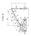
- the crane generally denoted at 10 includes a boom foot 102 mounted for swinging movement around a vertical swing shaft 101, and an extensible boom B consisting of N book embers B1 to B N is mounted on the boom foot 102.
- the boom B is constructed for pivotal movement (up and down tilting movement) around a horizontal pivot shaft 103, and a suspended cargo C is suspended at an end (boom point) of the boom B by means of a rope 104.
- outrigger jacks (projectable support members) 105 are disposed for sideward projection at four front and rear, left and right corners of a lower frame of the crane 10.
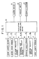
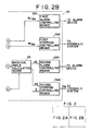
- a boom length sensor 11, a boom angle sensor 12, a cylinder pressure sensor 13, four outrigger jack projection amount sensors 14, a swinging angle sensor 15, an angular velocity sensor 16 and a rope length sensor 17 are disposed on the crane 10, and detection signals of those sensors 11 to 17 are transmitted to a calculating controlling device 20 while control signals are transmitted from the calculating controlling device 20 to an alarm device 31, a display unit 32 having a display screen and a hydraulic system 33 for the swinging movement.
- the calculating controlling device 20 is constructed so that it may execute roughly two controls including
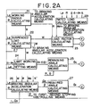
- the calculating controlling device 20 includes working radius calculating means 21 which calculates a working radius R of the suspended cargo C using a boom length L B and a boom angle ⁇ detected by the boom length sensor 11 and the boom angle sensor 12, respectively.
- Suspended load calculating means 22 calculates a load W of the suspended cargo C actually suspended on the boom B using such boom length L B and boom angle ⁇ and a cylinder pressure p of a boom upper cylinder detected by the cylinder pressure sensor 13.
- Rated load calculating means 221 calculates a rated load W0 using the working radius R, the boom length L B , a safety factor ⁇ , a swinging angle ⁇ detected by the swinging angle sensor 15 and projection amounts d1, d2, d3 and d4 detected by the outrigger jack extension amount sensors 14.
- Load factor calculating means 23 calculates a ratio of an actually suspended load W to the rated load W0, that is, a load factor W/W0.
- First alarm controlling means 291 delivers a control signal to the alarm device 31 to develop an alarm at a point of time when the load factor W/W0 calculated by the load factor calculating means 23 exceeds 90 %.
- First stopping controlling means 292 delivers, at a point of time when the load factor W/W0 exceeds 100 %, a control signal to the hydraulic system 33 to compulsorily stop a crane operation (such as extension or tilting down movement of the boom B, winding up of the suspended cargo C and so forth) except a swinging operation.
- a load factor W/W0 is thus calculated by such means described above, and a safety operation is controlled in response to the load factor W/W0.
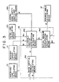
- Limit working region setting means 24 calculates a limit working region of the crane 10 under the conditions described above, that is, a region in which the end of the boom B can be moved within a safe region, using the suspended load W, the projection amounts d1 to d4 of the individual outrigger jacks 105 detected by the outrigger jack projection amount sensors 14 and the boom length L B .
- remaining angle calculating means 25 calculates a remaining angle ⁇ o over which the boom B can be swung from its current position until the limit working region is exceeded.
- braking angular acceleration calculating means 26 calculates an actual braking angular acceleration ⁇ using the working radius R, the suspended load W, the rated load W0, the boom length L B , the boom angle ⁇ , an angular velocity ⁇ 0 and a radius l of shaking movement of the suspended cargo C detected by the angular velocity sensor 16 and the rope length sensor 17, respectively, and a lateral bend safety coefficient ⁇ ′ set by lateral bend safety coefficient setting means 260 shown in Fig. 3.
- a lateral bend safety coefficient ⁇ ′ set by lateral bend safety coefficient setting means 260 shown in Fig. 3.
- the braking angular acceleration calculating means 26 includes boom inertial moment calculating means 261, allowable angular acceleration calculating means 262 and actual angular acceleration calculating means 263 and calculates a braking angular acceleration ⁇ with which no shaking movement of the suspended cargo C will be left upon stopping and which takes lateral bend strength of the boom B against inertial force upon braking or stopping into consideration.
- Required angle calculating means 27 calculates, using an angular velocity ⁇ 0 before starting of braking against swinging, an angle (required angle)
- Marginal angle calculating means 28 calculates a marginal angle ⁇ which is a difference between the remaining angle ⁇ o and the required angle
- Second alarm controlling means 293 delivers a control signal to the alarm device 31 to provide an alarm at a point of time when the calculated marginal angle ⁇ becomes smaller than a predetermined value.
- Second stopping controlling means 294 delivers, at a point of time when the marginal angle ⁇ is reduced to 0, a control signal to a motor in the hydraulic system 33 to brake and stop swinging movement of the boom B at the braking angular acceleration ⁇ and to compulsorily stop any movement which involves an increase of the working radius.
- a limit working region is set by the means described so far, and a safety operation is controlled based on comparison of the limit working region and a current working condition.
- the working radius calculating means 21 first calculates, using a boom length L B and a boom angle ⁇ , a working radius R′ which does not take a lateral bend of the boom B taken into consideration and a radius increment ⁇ R arising from a lateral bend of the boom B, and then calculates a working radius R using the working radius R′ and the radius increment ⁇ R.
- the suspended load calculating means 22 calculates a load W of an actually suspended cargo C using the thus calculated working radius R, the boom length L B and a cylinder pressure p.
- the rated load calculating means 221 either recalls a rated load W0 corresponding to a current swinging angle ⁇ from within a memory in which set rated loads are stored or calculates such rated load W0 from one of values of the memory by an interpolation calculation using the working radius R, the boom length L B , projection amounts of the outrigger jacks 105 and a predetermined coefficient ⁇ . Further, the load factor calculating 23 calculates a load factor W/W0 using the rated load W0.
- the limit working region setting means 24 sets a limit working region in response to the suspended load W, projection amounts d1 to d4 of the individual outrigger jacks 105 and the boom length L B .
- FIG. 4 A manner of such setting is illustrated in Fig. 4.
- straight lines are first drawn from the center O of swinging movement of the crane 10 to projected positions FL, FR, RL and RR of the individual outrigger jacks 105, and lines displaced by a predetermined fixed angle ⁇ from those of the straight lines on the side on which projection amounts of the outrigger jacks 105 are smaller (on the left-hand side of the crane 10 in the case shown in Fig. 4) are determined as boundary lines 41 and 42.
- a region on the right-hand side of the crane 10 with respect to the boundary provided by the boundary lines 41 and 42 is determined as a stable section, and in this section, a maximum allowable working radius (first allowable working radius) r1 corresponding to the actual suspended load W is set.
- a limit working region in this section makes a sectoral shape surrounded by an arc 43 having a radius equal to r1.
- the four outrigger jacks 105 are all projected to the utmost, then all the inside of a full circle having the radius r1 makes a limit working region.
- a region on the left-hand side of the crane 10 with respect to the boundary provided by the boundary lines 41 and 42 is determined as an unstable section.
- a limit working region defined by an arc 44 having a second allowable working radius r2 smaller than the first allowable working radius r1 is set (refer to an alternate long and two short dashes line of Fig. 4), but in the present arrangement, also as shown in Fig. 5, tangential lines L1 and L2 are drawn from boundary points P1 and P2 on the individual boundary lines 41 and 42 to the arc 44. and a region defined by the tangential lines L1 and L2 and part of the arc 44 is set as a limit working region.
- R r1 (constant)
- R r2 ⁇ r1 (constant)
- any other region that is, as to portions of the tangential lines L1 and L2, where a swinging angle at a location where the circle 44 changes into the straight line L1 as shown in Fig. 5 is represented by ⁇ 0
- the allowable working radii r1 and r2 may be calculated successively in response to a suspended load W or otherwise values thereof may be stored in a memory for individual divided stages of the suspended load W.
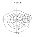
- limit working regions corresponding to the individual suspended loads W all make substantially similar shapes as shown in Fig. 6 (refer to a solid line 62 and alternate long and short dashes lines 61, 63 and 64).
- the remaining angle calculating means 25 calculates, using the current working radius R and swinging angle ⁇ , a remaining angle ⁇ o until the limit working region is exceeded by swinging movement.
- the limit working region is the inside of the thick solid line 62 shown in Fig. 6.
- the position of the current boom point is represented by A and swinging movement is performed with the same working radius in the direction of A ⁇ B ⁇ C, where the intersecting point of an arc with center at the center O of the swinging movement and the regional line of the limit working region is represented by C, then the angle defined by straight lines OA and OC is a remaining angle ⁇ o .
- the braking angular acceleration calculating means 26 follows the following procedure to calculate a braking angular acceleration ⁇ which takes lateral bend strength of the boom B into consideration and with which a shake of the cargo will not be left.
- the boom inertial moment calculating means 261 first calculates inertial moments I n of the individual boom members B n in accordance with the following expression.
- I n I n0 ⁇ cos2 ⁇ + (W n /g) ⁇ R n 2
- I0 is an inertial moment (constant) around the center of gravity of each boom member B n
- W n is a self weight of each boom member B n
- g is the acceleration of free fall
- R n is a swinging radius of the center of gravity of each boom member B n .
- the allowable angular acceleration calculating means 262 calculates an allowable angular acceleration ⁇ 1 in the following manner.
- the boom B and the boom foot 102 of the crane 10 have sufficient strengths. However, if the boom length L B increases, then great bending force arising from inertial force which is generated upon braking against swinging movement acts upon the boom B. Since the burden in strength by such lateral bending force is maximum around the boom foot 102, strength evaluation will be performed here based on a moment around the swinging axis 101.
- the angular acceleration ⁇ ⁇ of the suspended cargo C at the point of time is twice the angular acceleration ⁇ ′ of the boom B.
- the suspended cargo C is sometimes shaking upon starting of braking against swinging movement, and if such shake is present, the angular acceleration ⁇ ⁇ of the suspended cargo C during braking may exceed the twice the angular acceleration ⁇ ′ of the boom B.
- the maximum angular acceleration ⁇ ′ which satisfies the expression (4) should be set as the allowable angular acceleration at it is to be noted that, while the evaluation coefficient ⁇ ′ may be set to a fixed value, it may be set otherwise such that it may decrease as the working radius R of the boom L B increases.
- the actual angular acceleration calculating means 263 calculates an actual braking angular acceleration ⁇ using the allowable angular acceleration ⁇ 1 calculated in this manner and a boom angular velocity (angular velocity before deceleration) ⁇ 0 and a cargo shaking radius l which are both calculated using results of detection of the angular velocity sensor 16 and the rope length sensor 17, respectively.
- the required angle calculating means 27 calculates, using a current angular velocity (that is. an angular velocity before braking) ⁇ 0, a swinging angle (required angle)
- a current angular velocity that is. an angular velocity before braking
- the second stopping controlling means 294 delivers a control signal to the hydraulic system 33 at a point of time when the calculated marginal angle ⁇ is reduced to 0, for example. at a point of time when the boom B comes to the position D in Fig. 6 to perform braking against swinging movement of the boom 9 and compulsory stopping of an operation in which the working radius is increased.
- the hydraulic motor pressure P B is set so that braking and stopping may be performed at the braking angular acceleration ⁇ .
- the motor pressure difference ⁇ P1 represents a value of the pressure difference ⁇ P at an intersecting point between a straight line represented by the expression (10) given above and another straight line represented by the expression (11) given above.
- the second alarm controlling means 293 delivers a control signal to the alarm device 31 at a point of time at which the marginal angle ⁇ is reduced not to 0 but to a value smaller than a predetermined value so as to provide an alarm.
- the operator can know that braking will be rendered effective automatically after further small swinging movement.
- the calculating controlling device 20 delivers information signals regarding the individual values to the display unit 32 so as to provide such a screen indication as shown in Fig. 6.
- the display unit 32 indicates, on the screen thereof, a position of the lower frame of the crane 10, projected positions FL, FR, RL and RR of the individual outrigger jacks 105, a limit working region (the solid line 62 in case the suspended load W is, for example, 10 tons), and a line segment 60 which represents both of a working radius R and a swinging angle ⁇ . Consequently, the operator can recognize a relationship between current working conditions and a limit working region at a glance.
- the working radius R is first fixed by the first stopping controlling means 292, and then braking and stopping of swinging movement is performed by the second stopping controlling means 294.
- the reason why the working radius R is fixed is that, if braking is performed otherwise while the working radius is being expanded, then the final stopping point will exceed the limit working region. In other words, if braking is started while the working radius R is held fixed to r3 in this manner. swinging movement is stopped completely at a point Q5 on the boundary line of the limit working region.
- both of fixation of the working radius R and braking and stopping of swinging movement are executed by the second stopping controlling means 294.
- an alarm is provided at a point of time before the two angles become coincident with each other in order to draw an attention of an operator to control of the swinging velocity, and at the point at which the two angles coincide with each other, braking to swinging movement is started automatically at a braking angular acceleration with which no shake of the cargo will be left.
- the operator of the crane can recognize a relationship between swinging conditions including a swinging angular velocity and the limit working region accurately at a glance, and consequently, precise swinging operation which takes the safety into consideration can be performed.
Applications Claiming Priority (4)
| Application Number | Priority Date | Filing Date | Title |
|---|---|---|---|
| JP251250/89 | 1989-09-27 | ||
| JP25125089 | 1989-09-27 | ||
| JP2077258A JPH085623B2 (ja) | 1989-09-27 | 1990-03-26 | クレーンの安全装置 |
| JP77258/90 | 1990-03-26 |
Publications (3)
| Publication Number | Publication Date |
|---|---|
| EP0420625A2 true EP0420625A2 (de) | 1991-04-03 |
| EP0420625A3 EP0420625A3 (en) | 1992-03-18 |
| EP0420625B1 EP0420625B1 (de) | 1995-07-19 |
Family
ID=26418357
Family Applications (1)
| Application Number | Title | Priority Date | Filing Date |
|---|---|---|---|
| EP90310556A Expired - Lifetime EP0420625B1 (de) | 1989-09-27 | 1990-09-27 | Kran-Sicherheitssystem |
Country Status (6)
| Country | Link |
|---|---|
| US (1) | US5160056A (de) |
| EP (1) | EP0420625B1 (de) |
| JP (1) | JPH085623B2 (de) |
| KR (1) | KR930005026B1 (de) |
| DE (1) | DE69020999T2 (de) |
| ES (1) | ES2077031T3 (de) |
Cited By (15)
| Publication number | Priority date | Publication date | Assignee | Title |
|---|---|---|---|---|
| EP0539207A1 (de) * | 1991-10-24 | 1993-04-28 | Kabushiki Kaisha Kobe Seiko Sho | Sicherheitsvorrichtung für eine Baumaschine |
| EP0580007A1 (de) * | 1992-07-21 | 1994-01-26 | A. WEBER ANLAGENBAU GmbH & Co. KG | Steuerung für das Verschwenken eines in seiner effektiven Länge veränderlichen Auslegers |
| FR2720438A1 (fr) * | 1994-05-30 | 1995-12-01 | Camiva | Procédé de contrôle en déplacement d'un moyen élévateur. |
| FR2732001A1 (fr) * | 1995-03-24 | 1996-09-27 | Manitou Bf | Dispositif elevateur de personnel |
| EP0779237A3 (de) * | 1995-12-15 | 1997-07-09 | Liebherr-Werk Ehingen GmbH | Kranfahrzeug mit einer Überlastsicherungseinrichtung |
| EP1306343A2 (de) * | 1995-03-03 | 2003-05-02 | Komatsu Ltd. | Autokran mit einem Reichweiteanzeigegerät |
| EP1312579A2 (de) * | 2001-10-29 | 2003-05-21 | Ingersoll-Rand Company | Materialladefahrzeug mit einer elektronischen Darstellung der Last |
| CN102915045A (zh) * | 2012-10-31 | 2013-02-06 | 中联重科股份有限公司 | 一种臂架类工程车辆的控制方法及装置 |
| CN103613019A (zh) * | 2013-12-18 | 2014-03-05 | 山东建筑大学 | 一种验证塔式起重机起重量信号的方法与装置 |
| US9902596B2 (en) | 2012-06-01 | 2018-02-27 | Seatrax, Inc. | System and method to determine relative velocity of crane and target load |
| CN110997551A (zh) * | 2017-08-08 | 2020-04-10 | 株式会社多田野 | 过载保护装置 |
| CN110997550A (zh) * | 2017-08-08 | 2020-04-10 | 株式会社多田野 | 过负载防止装置 |
| CN111689400A (zh) * | 2020-05-21 | 2020-09-22 | 湖南中联重科建筑起重机械有限责任公司 | 塔机工作区域管控方法及设备 |
| EP3770103A4 (de) * | 2018-03-19 | 2021-12-08 | Tadano Ltd. | Kran und kransteuerungsverfahren |
| CN116380509A (zh) * | 2023-03-09 | 2023-07-04 | 江苏省特种设备安全监督检验研究院 | 起重机多工况模拟试验方法及模拟试验系统 |
Families Citing this family (43)
| Publication number | Priority date | Publication date | Assignee | Title |
|---|---|---|---|---|
| US6758356B1 (en) | 1989-10-10 | 2004-07-06 | Manitowoc Crane Companies, Inc. | Liftcrane with synchronous rope operation |
| US5579931A (en) * | 1989-10-10 | 1996-12-03 | Manitowoc Engineering Company | Liftcrane with synchronous rope operation |
| US5297019A (en) * | 1989-10-10 | 1994-03-22 | The Manitowoc Company, Inc. | Control and hydraulic system for liftcrane |
| US5251768A (en) * | 1990-03-23 | 1993-10-12 | Kabushiki Kaisha Kobe Seiko Sho | Method and device for controlling braking of an upper rotary body of a construction machine and a device for calculating the inclination angle of the upper rotary body |
| US5282136A (en) * | 1990-03-30 | 1994-01-25 | Kabushiki Kaisha Kobe Seiko Sho | Vertical releasing control device of crane hanging load |
| JPH0776490A (ja) * | 1993-09-09 | 1995-03-20 | Komatsu Ltd | クレーンの旋回自動停止制御装置 |
| JPH07187568A (ja) * | 1993-12-28 | 1995-07-25 | Komatsu Ltd | クレーンの制御装置 |
| KR970003508B1 (ko) * | 1994-03-25 | 1997-03-18 | 한국원자력연구소 | 크레인의 진동방지를 위한 속도 제어 방법 |
| US5479727A (en) * | 1994-10-25 | 1996-01-02 | Air Products And Chemicals, Inc. | Moisture removal and passivation of surfaces |
| KR100335458B1 (ko) * | 1995-01-23 | 2002-11-27 | 김병기 | 이동식기중기용하중표시장치 |
| EP0779239B2 (de) * | 1995-12-13 | 2006-09-13 | Liebherr-Werk Ehingen GmbH | Steuervorrichtung für ein Hubwerk eines Krans |
| DE29519871U1 (de) * | 1995-12-14 | 1996-03-21 | Liebherr Werk Ehingen | Kranfahrzeug |
| US6202013B1 (en) | 1998-01-15 | 2001-03-13 | Schwing America, Inc. | Articulated boom monitoring system |
| JP2000034093A (ja) | 1998-07-21 | 2000-02-02 | Kobe Steel Ltd | 旋回式作業機械とその安全作業領域及び定格荷重の設定方法 |
| DE10233875B4 (de) * | 2002-07-25 | 2008-08-14 | Siemens Ag | Krananlage, insbesondere Containerkran |
| DE102005035460A1 (de) * | 2005-07-28 | 2007-02-01 | Liebherr-Werk Ehingen Gmbh | Verfahren zur Traglastermittlung bei Kranen |
| US7489098B2 (en) | 2005-10-05 | 2009-02-10 | Oshkosh Corporation | System for monitoring load and angle for mobile lift device |
| US20080038106A1 (en) * | 2005-10-05 | 2008-02-14 | Oshkosh Truck Corporation | Mobile lift device |
| US7734397B2 (en) * | 2005-12-28 | 2010-06-08 | Wildcat Technologies, Llc | Method and system for tracking the positioning and limiting the movement of mobile machinery and its appendages |
| US20070266601A1 (en) * | 2006-05-19 | 2007-11-22 | Claxton Richard L | Device for measuring a load at the end of a rope wrapped over a rod |
| US8807910B1 (en) | 2007-05-31 | 2014-08-19 | Thomas V. Roden | Variable counterweight system for a material handling vehicle |
| US8007222B1 (en) * | 2007-05-31 | 2011-08-30 | ET&T Engineering LLP | Variable counterweight system for a material handling device |
| FI120789B (fi) * | 2008-06-23 | 2010-03-15 | Konecranes Oyj | Menetelmä nopeussäädettävän nostinkäytön moottorin pyörimisnopeuden ohjaamiseksi ja nostinkäyttö |
| JP4871968B2 (ja) * | 2009-02-17 | 2012-02-08 | 日立Geニュークリア・エナジー株式会社 | 重量構造物の据付工法 |
| JP4839390B2 (ja) * | 2009-04-17 | 2011-12-21 | 株式会社神戸製鋼所 | 旋回式作業機械の旋回停止制御装置および方法 |
| JP5480529B2 (ja) | 2009-04-17 | 2014-04-23 | 株式会社神戸製鋼所 | 旋回式作業機械の制動制御装置 |
| JP5173970B2 (ja) * | 2009-09-18 | 2013-04-03 | 株式会社神戸製鋼所 | 旋回式作業機械の旋回停止制御装置および方法 |
| JP5414048B2 (ja) * | 2009-10-13 | 2014-02-12 | キャタピラー エス エー アール エル | 解体作業機 |
| CN101746675B (zh) * | 2009-12-31 | 2012-05-02 | 三一汽车制造有限公司 | 起重机超起装置及其控制系统和控制方法 |
| KR20120079635A (ko) * | 2011-01-05 | 2012-07-13 | 삼성전자주식회사 | 호이스트 장치 및 그 제어 방법 |
| DE102011119654B4 (de) * | 2011-11-29 | 2015-11-12 | Liebherr-Werk Ehingen Gmbh | Mobile Arbeitsmaschine, insbesondere Fahrzeugkran |
| CN102491177B (zh) * | 2011-12-15 | 2013-12-25 | 中联重科股份有限公司 | 可回转工程机械及其回转控制方法与装置 |
| CN102491171A (zh) * | 2011-12-22 | 2012-06-13 | 上海三一科技有限公司 | 一种试验检测平台工装及包括该工装的起重机 |
| CN102627231B (zh) * | 2012-03-29 | 2014-03-26 | 中国科学院自动化研究所 | 一种幅度限制装置及方法 |
| US9327946B2 (en) * | 2012-07-16 | 2016-05-03 | Altec Industries, Inc. | Hydraulic side load braking system |
| JP6147062B2 (ja) * | 2013-04-02 | 2017-06-14 | 株式会社タダノ | 作業機の作業状態確認装置 |
| US11142434B1 (en) | 2014-02-18 | 2021-10-12 | Link-Belt Cranes, L.P., Lllp | Apparatus and methods for sensing boom side deflection or twist |
| JP6880648B2 (ja) | 2016-10-21 | 2021-06-02 | 株式会社タダノ | クレーン車 |
| JP7233240B2 (ja) * | 2019-02-19 | 2023-03-06 | Ihi運搬機械株式会社 | 軌道走行式クレーン |
| JP7416065B2 (ja) * | 2019-06-20 | 2024-01-17 | 株式会社タダノ | 可動範囲表示システムおよび可動範囲表示システムを備えるクレーン |
| US11647686B2 (en) * | 2020-03-26 | 2023-05-16 | Deere & Company | System and method for communicating the presence of proximate objects in a working area |
| CN113733040A (zh) * | 2021-09-14 | 2021-12-03 | 广东博智林机器人有限公司 | 作业机器人的安全监控方法、装置和作业机器人 |
| CN114014226A (zh) * | 2021-11-15 | 2022-02-08 | 徐州徐工随车起重机有限公司 | 一种高空作业车幅度限制系统及幅度限制方法 |
Citations (3)
| Publication number | Priority date | Publication date | Assignee | Title |
|---|---|---|---|---|
| EP0063709A1 (de) * | 1981-04-22 | 1982-11-03 | CAMIVA Société anonyme dite : | Steuerungsvorrichtung zum automatischen Korrigieren der Schiefstellung einer ausfahrbaren Drehleiter oder eines entsprechenden Hebearmes auf Fahrzeugen |
| EP0154069A2 (de) * | 1984-03-08 | 1985-09-11 | Merryweather And Sons Limited | Steuereinrichtung für eine aufrichtbare und ausfahrbare Struktur |
| GB2204014A (en) * | 1987-04-29 | 1988-11-02 | Scott Jcb Limited | Slew control system |
Family Cites Families (5)
| Publication number | Priority date | Publication date | Assignee | Title |
|---|---|---|---|---|
| US2916162A (en) * | 1953-11-06 | 1959-12-08 | Maschf Augsburg Nuernberg Ag | Apparatus for damping pendulum motions of the load suspended from a lifting machine |
| US4252243A (en) * | 1978-01-19 | 1981-02-24 | Priestman Brothers Limited | Crane safety device |
| US4216868A (en) * | 1978-08-04 | 1980-08-12 | Eaton Corporation | Optical digital sensor for crane operating aid |
| JPS58202291A (ja) * | 1982-05-18 | 1983-11-25 | 株式会社タダノ | 建設機械の過負荷防止装置 |
| US4997095A (en) * | 1989-04-20 | 1991-03-05 | The United States Of America As Represented By The United States Department Of Energy | Methods of and system for swing damping movement of suspended objects |
-
1990
- 1990-03-26 JP JP2077258A patent/JPH085623B2/ja not_active Expired - Fee Related
- 1990-09-27 EP EP90310556A patent/EP0420625B1/de not_active Expired - Lifetime
- 1990-09-27 US US07/588,929 patent/US5160056A/en not_active Expired - Lifetime
- 1990-09-27 DE DE69020999T patent/DE69020999T2/de not_active Expired - Fee Related
- 1990-09-27 KR KR1019900015395A patent/KR930005026B1/ko not_active IP Right Cessation
- 1990-09-27 ES ES90310556T patent/ES2077031T3/es not_active Expired - Lifetime
Patent Citations (3)
| Publication number | Priority date | Publication date | Assignee | Title |
|---|---|---|---|---|
| EP0063709A1 (de) * | 1981-04-22 | 1982-11-03 | CAMIVA Société anonyme dite : | Steuerungsvorrichtung zum automatischen Korrigieren der Schiefstellung einer ausfahrbaren Drehleiter oder eines entsprechenden Hebearmes auf Fahrzeugen |
| EP0154069A2 (de) * | 1984-03-08 | 1985-09-11 | Merryweather And Sons Limited | Steuereinrichtung für eine aufrichtbare und ausfahrbare Struktur |
| GB2204014A (en) * | 1987-04-29 | 1988-11-02 | Scott Jcb Limited | Slew control system |
Cited By (25)
| Publication number | Priority date | Publication date | Assignee | Title |
|---|---|---|---|---|
| EP0539207A1 (de) * | 1991-10-24 | 1993-04-28 | Kabushiki Kaisha Kobe Seiko Sho | Sicherheitsvorrichtung für eine Baumaschine |
| EP0580007A1 (de) * | 1992-07-21 | 1994-01-26 | A. WEBER ANLAGENBAU GmbH & Co. KG | Steuerung für das Verschwenken eines in seiner effektiven Länge veränderlichen Auslegers |
| FR2720438A1 (fr) * | 1994-05-30 | 1995-12-01 | Camiva | Procédé de contrôle en déplacement d'un moyen élévateur. |
| EP1306343A2 (de) * | 1995-03-03 | 2003-05-02 | Komatsu Ltd. | Autokran mit einem Reichweiteanzeigegerät |
| EP1306343A3 (de) * | 1995-03-03 | 2003-05-21 | Komatsu Ltd. | Autokran mit einem Reichweiteanzeigegerät |
| FR2732001A1 (fr) * | 1995-03-24 | 1996-09-27 | Manitou Bf | Dispositif elevateur de personnel |
| EP0779237A3 (de) * | 1995-12-15 | 1997-07-09 | Liebherr-Werk Ehingen GmbH | Kranfahrzeug mit einer Überlastsicherungseinrichtung |
| EP1312579A2 (de) * | 2001-10-29 | 2003-05-21 | Ingersoll-Rand Company | Materialladefahrzeug mit einer elektronischen Darstellung der Last |
| US9902596B2 (en) | 2012-06-01 | 2018-02-27 | Seatrax, Inc. | System and method to determine relative velocity of crane and target load |
| CN102915045B (zh) * | 2012-10-31 | 2015-01-07 | 中联重科股份有限公司 | 一种臂架类工程车辆的控制方法及装置 |
| CN102915045A (zh) * | 2012-10-31 | 2013-02-06 | 中联重科股份有限公司 | 一种臂架类工程车辆的控制方法及装置 |
| CN103613019A (zh) * | 2013-12-18 | 2014-03-05 | 山东建筑大学 | 一种验证塔式起重机起重量信号的方法与装置 |
| CN103613019B (zh) * | 2013-12-18 | 2016-04-06 | 山东建筑大学 | 一种验证塔式起重机起重量信号的方法与装置 |
| CN110997551B (zh) * | 2017-08-08 | 2021-10-08 | 株式会社多田野 | 过载保护装置 |
| CN110997550A (zh) * | 2017-08-08 | 2020-04-10 | 株式会社多田野 | 过负载防止装置 |
| EP3666718A4 (de) * | 2017-08-08 | 2020-08-26 | Tadano Ltd. | Vorrichtung zur überlastverhinderung |
| EP3666717A4 (de) * | 2017-08-08 | 2020-08-26 | Tadano Ltd. | Vorrichtung zur überlastverhinderung |
| US10865080B2 (en) | 2017-08-08 | 2020-12-15 | Tadano Ltd. | Overload preventing device |
| US10919739B2 (en) | 2017-08-08 | 2021-02-16 | Tadano Ltd. | Overload preventing device |
| CN110997550B (zh) * | 2017-08-08 | 2021-07-02 | 株式会社多田野 | 过负载防止装置 |
| CN110997551A (zh) * | 2017-08-08 | 2020-04-10 | 株式会社多田野 | 过载保护装置 |
| EP3770103A4 (de) * | 2018-03-19 | 2021-12-08 | Tadano Ltd. | Kran und kransteuerungsverfahren |
| CN111689400A (zh) * | 2020-05-21 | 2020-09-22 | 湖南中联重科建筑起重机械有限责任公司 | 塔机工作区域管控方法及设备 |
| CN116380509A (zh) * | 2023-03-09 | 2023-07-04 | 江苏省特种设备安全监督检验研究院 | 起重机多工况模拟试验方法及模拟试验系统 |
| CN116380509B (zh) * | 2023-03-09 | 2023-10-20 | 江苏省特种设备安全监督检验研究院 | 起重机多工况模拟试验方法及模拟试验系统 |
Also Published As
| Publication number | Publication date |
|---|---|
| ES2077031T3 (es) | 1995-11-16 |
| KR910006135A (ko) | 1991-04-27 |
| JPH085623B2 (ja) | 1996-01-24 |
| DE69020999D1 (de) | 1995-08-24 |
| EP0420625B1 (de) | 1995-07-19 |
| US5160056A (en) | 1992-11-03 |
| KR930005026B1 (ko) | 1993-06-12 |
| DE69020999T2 (de) | 1995-11-23 |
| EP0420625A3 (en) | 1992-03-18 |
| JPH03177299A (ja) | 1991-08-01 |
Similar Documents
| Publication | Publication Date | Title |
|---|---|---|
| EP0420625A2 (de) | Kran-Sicherheitssystem | |
| KR960008350B1 (ko) | 건설기계의 안전장치 | |
| US6170681B1 (en) | Swing type machine and method for setting a safe work area and a rated load in same | |
| EP0473784A1 (de) | Verfahren und vorrichtung zur steuerung des abbremsens der drehbewegung des oberen drehteils von baumaschinen und rechengerät zur ermittlung des neigungswinkels | |
| EP0728696A1 (de) | Vorrichtung zum detektieren von last- und kippmoment für einen beweglichen kran | |
| KR960000109B1 (ko) | 건설기계의 상부 선회체 선회정지 제어방법 및 그 제어장치 | |
| JPH05319785A (ja) | 建設機械の姿勢制御システム | |
| JP3303953B2 (ja) | 作業車両の転倒警報装置及び転倒防止方法 | |
| JPH026282A (ja) | ホイール走行車両の転倒防止装置 | |
| JPH0829917B2 (ja) | クレーンの安全装置 | |
| JPS5970919A (ja) | 揺動等による積載重量測定誤差算出装置 | |
| JPH10291779A (ja) | クレーンの転倒防止装置および方法 | |
| JP2501995B2 (ja) | クレ―ンの旋回停止制御方法および装置 | |
| JP2512821B2 (ja) | クレ―ンの旋回停止制御方法および装置 | |
| JPH07106876B2 (ja) | 建設機械の安全装置 | |
| JP2786177B2 (ja) | クレーンの制御方法 | |
| JP2564061B2 (ja) | 建設機械の安全装置 | |
| JP2942666B2 (ja) | 作業機械の安全装置 | |
| JPH038699A (ja) | 移動式クレーンのアウトリガ反力表示装置 | |
| JPH0632588A (ja) | 建設機械の作業状態表示装置 | |
| JP3596931B2 (ja) | 建設機械の負荷状態検出装置 | |
| JPH0211518B2 (de) | ||
| JPH0729110Y2 (ja) | 移動式クレーンのブーム煽り予知装置 | |
| JPH0646947Y2 (ja) | レベリング装置 | |
| JP3073310B2 (ja) | 移動式クレーンの旋回制動開始信号発生装置 |
Legal Events
| Date | Code | Title | Description |
|---|---|---|---|
| PUAI | Public reference made under article 153(3) epc to a published international application that has entered the european phase |
Free format text: ORIGINAL CODE: 0009012 |
|
| 17P | Request for examination filed |
Effective date: 19901004 |
|
| AK | Designated contracting states |
Kind code of ref document: A2 Designated state(s): DE ES FR GB IT NL |
|
| PUAL | Search report despatched |
Free format text: ORIGINAL CODE: 0009013 |
|
| AK | Designated contracting states |
Kind code of ref document: A3 Designated state(s): DE ES FR GB IT NL |
|
| 17Q | First examination report despatched |
Effective date: 19940331 |
|
| GRAA | (expected) grant |
Free format text: ORIGINAL CODE: 0009210 |
|
| AK | Designated contracting states |
Kind code of ref document: B1 Designated state(s): DE ES FR GB IT NL |
|
| ET | Fr: translation filed | ||
| REF | Corresponds to: |
Ref document number: 69020999 Country of ref document: DE Date of ref document: 19950824 |
|
| ITF | It: translation for a ep patent filed |
Owner name: ING. C. GREGORJ S.P.A. |
|
| REG | Reference to a national code |
Ref country code: ES Ref legal event code: FG2A Ref document number: 2077031 Country of ref document: ES Kind code of ref document: T3 |
|
| PLBE | No opposition filed within time limit |
Free format text: ORIGINAL CODE: 0009261 |
|
| STAA | Information on the status of an ep patent application or granted ep patent |
Free format text: STATUS: NO OPPOSITION FILED WITHIN TIME LIMIT |
|
| 26N | No opposition filed | ||
| PGFP | Annual fee paid to national office [announced via postgrant information from national office to epo] |
Ref country code: FR Payment date: 20010911 Year of fee payment: 12 |
|
| PGFP | Annual fee paid to national office [announced via postgrant information from national office to epo] |
Ref country code: GB Payment date: 20010926 Year of fee payment: 12 |
|
| PGFP | Annual fee paid to national office [announced via postgrant information from national office to epo] |
Ref country code: ES Payment date: 20010928 Year of fee payment: 12 |
|
| PGFP | Annual fee paid to national office [announced via postgrant information from national office to epo] |
Ref country code: NL Payment date: 20010930 Year of fee payment: 12 |
|
| REG | Reference to a national code |
Ref country code: GB Ref legal event code: IF02 |
|
| PG25 | Lapsed in a contracting state [announced via postgrant information from national office to epo] |
Ref country code: GB Free format text: LAPSE BECAUSE OF NON-PAYMENT OF DUE FEES Effective date: 20020927 |
|
| PG25 | Lapsed in a contracting state [announced via postgrant information from national office to epo] |
Ref country code: ES Free format text: LAPSE BECAUSE OF NON-PAYMENT OF DUE FEES Effective date: 20020928 |
|
| PG25 | Lapsed in a contracting state [announced via postgrant information from national office to epo] |
Ref country code: NL Free format text: LAPSE BECAUSE OF NON-PAYMENT OF DUE FEES Effective date: 20030401 |
|
| GBPC | Gb: european patent ceased through non-payment of renewal fee |
Effective date: 20020927 |
|
| PG25 | Lapsed in a contracting state [announced via postgrant information from national office to epo] |
Ref country code: FR Free format text: LAPSE BECAUSE OF NON-PAYMENT OF DUE FEES Effective date: 20030603 |
|
| REG | Reference to a national code |
Ref country code: FR Ref legal event code: ST |
|
| REG | Reference to a national code |
Ref country code: ES Ref legal event code: FD2A Effective date: 20031011 |
|
| PGFP | Annual fee paid to national office [announced via postgrant information from national office to epo] |
Ref country code: DE Payment date: 20050922 Year of fee payment: 16 |
|
| PG25 | Lapsed in a contracting state [announced via postgrant information from national office to epo] |
Ref country code: IT Free format text: LAPSE BECAUSE OF NON-PAYMENT OF DUE FEES;WARNING: LAPSES OF ITALIAN PATENTS WITH EFFECTIVE DATE BEFORE 2007 MAY HAVE OCCURRED AT ANY TIME BEFORE 2007. THE CORRECT EFFECTIVE DATE MAY BE DIFFERENT FROM THE ONE RECORDED. Effective date: 20050927 |
|
| PG25 | Lapsed in a contracting state [announced via postgrant information from national office to epo] |
Ref country code: DE Free format text: LAPSE BECAUSE OF NON-PAYMENT OF DUE FEES Effective date: 20070403 |