EP0363808B1 - Vorrichtung zum Bilden einer Dreherkante - Google Patents
Vorrichtung zum Bilden einer Dreherkante Download PDFInfo
- Publication number
- EP0363808B1 EP0363808B1 EP89118431A EP89118431A EP0363808B1 EP 0363808 B1 EP0363808 B1 EP 0363808B1 EP 89118431 A EP89118431 A EP 89118431A EP 89118431 A EP89118431 A EP 89118431A EP 0363808 B1 EP0363808 B1 EP 0363808B1
- Authority
- EP
- European Patent Office
- Prior art keywords
- frame
- rail
- rails
- thread guide
- guide element
- Prior art date
- Legal status (The legal status is an assumption and is not a legal conclusion. Google has not performed a legal analysis and makes no representation as to the accuracy of the status listed.)
- Expired - Lifetime
Links
- 239000002184 metal Substances 0.000 claims description 16
- 229920003023 plastic Polymers 0.000 claims description 6
- 239000004033 plastic Substances 0.000 claims description 6
- 229910000831 Steel Inorganic materials 0.000 claims description 2
- 239000010959 steel Substances 0.000 claims description 2
- 230000015572 biosynthetic process Effects 0.000 claims 1
- 239000000463 material Substances 0.000 claims 1
- 238000009941 weaving Methods 0.000 description 2
- JEIPFZHSYJVQDO-UHFFFAOYSA-N iron(III) oxide Inorganic materials O=[Fe]O[Fe]=O JEIPFZHSYJVQDO-UHFFFAOYSA-N 0.000 description 1
Images
Classifications
-
- D—TEXTILES; PAPER
- D03—WEAVING
- D03C—SHEDDING MECHANISMS; PATTERN CARDS OR CHAINS; PUNCHING OF CARDS; DESIGNING PATTERNS
- D03C7/00—Leno or similar shedding mechanisms
Definitions
- the invention relates to a device for forming a leno selvedge consisting of mutually moving heald frames, a thread guide device being attached to one heald frame and a needle holder having two parallel, essentially U-shaped frame rails, which holding a thread guide element, is arranged on the other heald frame.
- a device of the type mentioned is known for example from German utility model 79 31 872. It has been shown that these frame rails are subject to high wear, especially when the magnets arranged in the thread guide element come into direct contact with the frame rail. If the frame rails of a needle holder are worn out to such an extent that the thread guide element is no longer properly guided, so that there is a risk of binding errors, the entire needle holder must be replaced, which is expensive.
- a leno device is known with a guide frame which guides a warp thread holder in the frame rails, a thread guide device being guided in the parallel frame rails.
- a guide frame which guides a warp thread holder in the frame rails
- a thread guide device being guided in the parallel frame rails.
- needle bearing strips are provided in the end faces of the rails. The wear problem is solved by the arrangement of needle bearing strips, which have low friction.
- the invention has for its object to provide a needle holder in which the wear problem is solved with simpler means.
- a groove is arranged in each leg base of one leg of the U-shaped frame rail, which is used to receive and guide the metal rail.
- frame rails made of plastic could not be used.
- a frame rail made of plastic can now also be used; the magnetic braking of the thread guide element now takes place in cooperation with the metal rail.
- Frame rails made of plastic have the advantage of lower weight, which opens up the possibility of increasing the number of strokes of a weaving machine.
- Metal rails which according to the prior art are only nickel-plated for protection against rust, also have the disadvantage that they quickly become rusty when used in wet weaving. This is impossible with plastic frame rails.
- the metal rail itself is made of rustproof but magnetic steel.
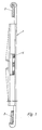
- a device for forming a leno selvedge consists of reciprocating heald frames, a needle holder being arranged on one heald frame and the other heald frame having a thread guiding device.
- the second heald frame with the thread guide device arranged thereon has been omitted in FIG. 1.
- the needle holder designated as a whole by 1, is arranged on the heald frame 2.
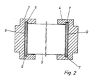
- the needle holder 1 consists of the two parallel frame rails 3 and 4, which serve to guide the thread guide element 5 (FIG. 2).
- the substantially U-shaped frame rail 3, 4 has a groove 6 and 7 in the leg base of each leg.
- the metal rails 8 and 9 are located in the grooves 6 and 7 respectively.
- the thread guide element 5 guided in the two frame rails 3, 4 is therefore not in direct contact with the frame rails, but is in contact with the metal rails 8, 9 on both sides. If the metal rails are worn, they can easily be replaced with new ones.
Landscapes
- Engineering & Computer Science (AREA)
- Textile Engineering (AREA)
- Looms (AREA)
- Treatment Of Fiber Materials (AREA)
- Making Paper Articles (AREA)
- Electrostatic Spraying Apparatus (AREA)
- Knitting Machines (AREA)
- Sewing Machines And Sewing (AREA)
Description
- Die Erfindung betrifft eine Vorrichtung zum Bilden einer Dreherkante, bestehend aus wechselseitig bewegten Webschäften, wobei an einem Webschaft eine Fadenführungseinrichtung angebracht ist und wobei an dem anderen Webschaft ein zwei parallele im wesentlichen U-förmig ausgebildete Gestellschienen aufweisender Nadelhalter angeordnet ist, der ein Fadenführungselement hält.
- Eine Vorrichtung der eingangs genannten Art ist beispielsweise aus dem deutschen Gebrauchsmuster 79 31 872 bekannt. Es hat sich gezeigt, daß diese Gestellschienen einem hohen Verschleiß unterworfen sind, und zwar insbesondere dann, wenn die in dem Fadenführungselement angeordneten Magnete unmittelbar mit der Gestellschiene in Berührung kommen. Sind die Gestellschienen eines Nadelhalters soweit verschlissen, daß das Fadenführungselement nicht mehr ordnungsgemäß geführt wird, so daß die Gefahr von Bindefehlern entsteht, muß der komplette Nadelhalter ausgetauscht werden, was teuer ist.
- Aus der Gebrauchsmusterschrift 88 04 913 ist eine Dreherkantenvorrichtung bekannt mit einem Führungsgestell, das einen Kettfadenhalter in den Gestellschienen führt, wobei in den parallelen Gestellschienen eine Fadenführungsvorrichtung geführt wird. Dabei sind zur Verminderung der Reibung der bewegten Teile in den Schienen jeweils in den Stirnseiten der Schienen Nadellagerleisten vorgesehen. Das Verschleißproblem wird dabei durch die Anordnung von Nadellagerleisten gelöst, die eine geringe Reibung aufweisen.
- Der Erfindung liegt die Aufgabe zugrunde, einen Nadelhalter zu schaffen, bei dem das Verschleißproblem mit einfacheren Mitteln gelöst wird. Das wird erfindungsgemäß dadurch erreicht, daß die Gestellschiene auf ihrer dem Fadenführungselement zugewandten Seite eine Einlage in Form einer Metallschiene aufweist, die austauschbar ist, wobei die Gestellschiene aus Kunststoff besteht.
- Durch diese Maßnahme wird ein Verschleiß an den Gestellschienen selbst vermieden; ist die Metallschiene verschlissen, so kann diese problemlos ausgetauscht werden. Zur Fixierung der Metallschiene in den Gestellschienen, ist jeweils in Schenkelgrund eines Schenkels der U-förmig ausgebildeten Gestellschiene eine Nut angeordnet, die der Aufnahme und Führung der Metallschiene dient.
- Da zur magnetischen Abbremsung des Fadenführungselementes die Gestellschiene immer metallisch ausgebildet sein muß, konnten Gestellschienen aus Kunststoff nicht zum Einsatz kommen. Durch den Einsatz der Metallschiene in die Gestellschiene kann nunmehr auch eine Gestellschiene aus Kunststoff zum Einsatz kommen; die magnetische Abbremsung des Fadenführungselementes erfolgt nunmehr in Zusammenarbeit mit der Metallschiene. Gestellschienen aus Kunststoff haben den Vorteil des geringeren Gewichts, wodurch sich die Möglichkeit eröffnet, die Hubzahl einer Webmaschine zu erhöhen.
- Metallschienen, die nach dem Stand der Technik zum Schutz gegen Rost lediglich vernickelt sind, haben darüber hinaus den Nachteil, daß sie beim Einsatz in der Naßweberei schnell Rost ansetzen. Das ist bei Gestellschienen aus Kunststoff ausgeschlossen. Die Metallschiene selbst besteht aus rostfreiem aber magnetischem Stahl.
- In der Zeichnung ist eine beispielsweise Ausführungsform dargestellt.
- Fig. 1
- zeigt die Vorrichtung zum Bilden einer Dreherkante in einer Seitenansicht;
- Fig. 2
- zeigt die zwei parallelen Gestellschienen eines Nadelhalters im Schnitt, wobei die Nadeln weggelassen sind.
- Gemäß Fig. 1 besteht eine Vorrichtung zum Bilden einer Dreherkante aus wechselseitig bewegten Webschäften, wobei an dem einen Webschaft ein Nadelhalter angeordnet ist, und der andere Webschaft eine Fadenführungseinrichtung aufweist. Zur besseren Übersicht ist in Fig. 1 der zweite Webschaft mit der daran angeordneten Fadenführungseinrichtung weggelassen worden.
- Gemäß Fig. 1 ist der insgesamt mit 1 bezeichnete Nadelhalter an den Webschaft 2 angeordnet. Der Nadelhalter 1 besteht aus den zwei parallelen Gestellschienen 3 und 4, die der Führung des Fadenführungselementes 5 dienen (Fig. 2). Die im wesentlichen U-förmig ausgebildete Gestellschiene 3, 4 weist im Schenkelgrund eines jeden Schenkels eine Nut 6 bzw. 7 auf. In den Nuten 6 bzw. 7 befindet sich die Metallschiene 8 bzw. 9. Das in den beiden Gestellschienen 3, 4 geführte Fadenführungselement 5 steht somit nicht unmittelbar mit den Gestellschienen in Berührung, sondern liegt beidseitig an den Metallschienen 8, 9 an. Sind die Metallschienen verschlissen, so können diese in einfacher Weise durch neue ersetzt werden.
Claims (4)
- Vorrichtung zum Bilden einer Dreherkante bestehend aus wechselseitig bewegten Webschäften, wobei an einem Webschaft eine Fadenführungsvorrichtung angebracht ist, und wobei an dem anderen Webschaft (2) ein zwei parallele im wesentlichen U-förmig ausgebildete Gestellschienen (3, 4) aufweisender Nadelhalter (1) angeordnet ist, der ein Fadenführungselement (5) hält,
dadurch gekennzeichnet, daß
die Gestellschiene (3, 4) auf ihrer dem Fadenführungselement (5) zugewandten Seite eine Einlage in Form einer Metallschiene (8, 9) aufweist, die austauschbar ist, wobei die Gestellschiene (3, 4) aus Kunststoff besteht. - Vorrichtung nach Anspruch 1
dadurch gekennzeichnet, daß
die Gestellschiene (3, 4) Mittel zur Fixierung der Metallschiene (8, 9) aufweist. - Vorrichtung nach Anspruch 2
dadurch gekennzeichnet, daß
zur Fixierung der Metallschiene (8, 9) die Gestellschiene (3, 4) jeweils im Schenkelgrund eines Schenkels eine Nut (6, 7) angeordnet ist. - Vorrichtung nach Anspruch 1
dadurch gekennzeichnet, daß
die Metallschiene (8, 9) aus rostfreiem, aber magnetischem Stahl besteht.
Priority Applications (1)
| Application Number | Priority Date | Filing Date | Title |
|---|---|---|---|
| AT89118431T ATE91161T1 (de) | 1988-10-14 | 1989-10-04 | Vorrichtung zum bilden einer dreherkante. |
Applications Claiming Priority (2)
| Application Number | Priority Date | Filing Date | Title |
|---|---|---|---|
| DE8812937U DE8812937U1 (de) | 1988-10-14 | 1988-10-14 | Vorrichtung zum Bilden einer Dreherkante |
| DE8812937U | 1988-10-14 |
Publications (2)
| Publication Number | Publication Date |
|---|---|
| EP0363808A1 EP0363808A1 (de) | 1990-04-18 |
| EP0363808B1 true EP0363808B1 (de) | 1993-06-30 |
Family
ID=6828875
Family Applications (1)
| Application Number | Title | Priority Date | Filing Date |
|---|---|---|---|
| EP89118431A Expired - Lifetime EP0363808B1 (de) | 1988-10-14 | 1989-10-04 | Vorrichtung zum Bilden einer Dreherkante |
Country Status (6)
| Country | Link |
|---|---|
| US (1) | US5048573A (de) |
| EP (1) | EP0363808B1 (de) |
| JP (1) | JPH02127537A (de) |
| AT (1) | ATE91161T1 (de) |
| DE (2) | DE8812937U1 (de) |
| ES (1) | ES2041929T3 (de) |
Families Citing this family (2)
| Publication number | Priority date | Publication date | Assignee | Title |
|---|---|---|---|---|
| DE4204629C1 (de) * | 1992-02-15 | 1993-03-04 | Kloecker-Entwicklungs-Gmbh, 4280 Borken, De | |
| DE10257519B3 (de) * | 2002-12-10 | 2004-04-01 | Klöcker-Entwicklungs-Gmbh | Vorrichtung zum Bilden einer Dreherkante |
Family Cites Families (12)
| Publication number | Priority date | Publication date | Assignee | Title |
|---|---|---|---|---|
| US2918945A (en) * | 1958-07-16 | 1959-12-29 | Crompton & Knowles Corp | Selvage and method and means for making same |
| US3650576A (en) * | 1970-11-20 | 1972-03-21 | Ingersoll Rand Co | Liner for aluminum drill guide feed |
| CH536375A (it) * | 1971-06-21 | 1973-04-30 | Somet Soc Mec Tessile | Dispositivo per la esecuzione del giro inglese nella formazione di cimosse sui telai di tessitura |
| US4324437A (en) * | 1978-05-12 | 1982-04-13 | Narang Rajendra K | Endless track |
| DE7931872U1 (de) * | 1979-11-12 | 1980-03-27 | Kloecker, Heinz, 4280 Borken | Vorrichtung zum bilden einer mit einer bindung versehenen gewebekante, insbesondere bei schuetzenlosen webmaschinen |
| CH639440A5 (de) * | 1979-09-05 | 1983-11-15 | Rueti Ag Maschf | Schussfadeneintragsorgan fuer webmaschinen mit entnahme des schussfadens von ortsfesten spulen. |
| CH639439A5 (de) * | 1979-09-05 | 1983-11-15 | Rueti Ag Maschf | Greiferkopf fuer webmaschinen mit entnahme des schussfadens von ortsfesten spulen. |
| IT1132580B (it) * | 1980-08-29 | 1986-07-02 | Nuovo Pignone Spa | Dispositivo perfezionato per la legatura a doppio giro inglese incrociato dei bordi laterali di un tessuto in un telaio tessile |
| DE3442204A1 (de) * | 1984-08-27 | 1986-03-06 | Klöcker-Entwicklungs-GmbH, 4280 Borken | Vorrichtung zur bildung einer dreherkante |
| JPS61172175U (de) * | 1985-04-17 | 1986-10-25 | ||
| DE3574884D1 (de) * | 1985-09-02 | 1990-01-25 | Sulzer Ag | Drehervorrichtung fuer webmaschinen. |
| DE8804913U1 (de) * | 1988-03-31 | 1988-08-18 | Klöcker-Entwicklungs-GmbH, 4280 Borken | Vorrichtung zum Bilden einer Dreherkante |
-
1988
- 1988-10-14 DE DE8812937U patent/DE8812937U1/de not_active Expired
-
1989
- 1989-10-04 ES ES198989118431T patent/ES2041929T3/es not_active Expired - Lifetime
- 1989-10-04 AT AT89118431T patent/ATE91161T1/de not_active IP Right Cessation
- 1989-10-04 EP EP89118431A patent/EP0363808B1/de not_active Expired - Lifetime
- 1989-10-04 DE DE8989118431T patent/DE58904837D1/de not_active Expired - Fee Related
- 1989-10-06 JP JP1260354A patent/JPH02127537A/ja active Granted
- 1989-10-11 US US07/419,889 patent/US5048573A/en not_active Expired - Fee Related
Also Published As
| Publication number | Publication date |
|---|---|
| JPH02127537A (ja) | 1990-05-16 |
| US5048573A (en) | 1991-09-17 |
| DE58904837D1 (de) | 1993-08-05 |
| DE8812937U1 (de) | 1989-01-05 |
| JPH0375651B2 (de) | 1991-12-02 |
| ATE91161T1 (de) | 1993-07-15 |
| ES2041929T3 (es) | 1993-12-01 |
| EP0363808A1 (de) | 1990-04-18 |
Similar Documents
| Publication | Publication Date | Title |
|---|---|---|
| CH477579A (de) | Fussbodenbelagmaterial aus Florgewebe | |
| EP0363808B1 (de) | Vorrichtung zum Bilden einer Dreherkante | |
| DE2217091A1 (de) | Weblitzenhalte- und Antriebsvorrichtung an Webmaschinen | |
| EP0214322B1 (de) | Drehervorrichtung für Webmaschinen | |
| DE2935504C2 (de) | Webelitze | |
| EP0282874B1 (de) | Zur Erzielung einer Dreherkante geeignete Webschaftvorrichtung | |
| DE3008987C2 (de) | ||
| DE3832622C1 (de) | ||
| DE3830107A1 (de) | Drehervorrichtung fuer webmaschinen | |
| DE69603553T2 (de) | Vorrichtung zum Eintrag von Schussfaden an einer Greiferwebmaschine | |
| EP0174533A2 (de) | Vorrichtung zur Bildung einer Dreherkante | |
| DE4000395C2 (de) | ||
| DE3414368C2 (de) | Webmaschine, insbesondere Frottierwebmaschine | |
| EP0233141B1 (de) | Greiferwebmaschine | |
| DE2916838C2 (de) | Vorrichtung zum Bilden einer mit einer Bindung versehenen Gewebekante, insbesondere bei schützenlosen Webmaschinen | |
| EP0980448B1 (de) | Greiferwebmaschine | |
| DE1710317C3 (de) | Verfahren und Vorrichtung zum Herstellen einer Dreherbindung | |
| DE2936116C2 (de) | Fadenklemme einer Webmaschine | |
| EP0248364B1 (de) | Vorrichtung zum Bilden einer mit einer Bindung versehenen Gewebekante | |
| AT16450B (de) | Verfahren und Vorrichtung zum Auseinanderstreichen, gleichmäßigen Verteilen und Aufrauhen der Kettenfäden an mechanischen Webstühlen. | |
| DE7931872U1 (de) | Vorrichtung zum bilden einer mit einer bindung versehenen gewebekante, insbesondere bei schuetzenlosen webmaschinen | |
| AT333680B (de) | Handwebgerat | |
| DE10053651C1 (de) | Vorrichtung zum Einziehen von Kettfäden in ein Doppelwebblatt | |
| DE3410754A1 (de) | Vorrichtung zum bilden einer mit einer bindung versehenen gewebekante | |
| DE2024571C3 (de) | SchuBfadenanschlagvorrichtung für Wellenwebmaschinen |
Legal Events
| Date | Code | Title | Description |
|---|---|---|---|
| PUAI | Public reference made under article 153(3) epc to a published international application that has entered the european phase |
Free format text: ORIGINAL CODE: 0009012 |
|
| AK | Designated contracting states |
Kind code of ref document: A1 Designated state(s): AT BE CH DE ES FR GB GR IT LI LU NL SE |
|
| 17P | Request for examination filed |
Effective date: 19900507 |
|
| 17Q | First examination report despatched |
Effective date: 19920226 |
|
| GRAA | (expected) grant |
Free format text: ORIGINAL CODE: 0009210 |
|
| AK | Designated contracting states |
Kind code of ref document: B1 Designated state(s): AT BE CH DE ES FR GB GR IT LI LU NL SE |
|
| REF | Corresponds to: |
Ref document number: 91161 Country of ref document: AT Date of ref document: 19930715 Kind code of ref document: T |
|
| REF | Corresponds to: |
Ref document number: 58904837 Country of ref document: DE Date of ref document: 19930805 |
|
| PGFP | Annual fee paid to national office [announced via postgrant information from national office to epo] |
Ref country code: GR Payment date: 19930818 Year of fee payment: 5 |
|
| PGFP | Annual fee paid to national office [announced via postgrant information from national office to epo] |
Ref country code: SE Payment date: 19930906 Year of fee payment: 5 |
|
| PGFP | Annual fee paid to national office [announced via postgrant information from national office to epo] |
Ref country code: LU Payment date: 19930922 Year of fee payment: 5 |
|
| ET | Fr: translation filed | ||
| PGFP | Annual fee paid to national office [announced via postgrant information from national office to epo] |
Ref country code: GB Payment date: 19930924 Year of fee payment: 5 |
|
| ITF | It: translation for a ep patent filed | ||
| REG | Reference to a national code |
Ref country code: GR Ref legal event code: FG4A Free format text: 3008382 |
|
| PGFP | Annual fee paid to national office [announced via postgrant information from national office to epo] |
Ref country code: ES Payment date: 19931005 Year of fee payment: 5 |
|
| PGFP | Annual fee paid to national office [announced via postgrant information from national office to epo] |
Ref country code: AT Payment date: 19931014 Year of fee payment: 5 |
|
| PGFP | Annual fee paid to national office [announced via postgrant information from national office to epo] |
Ref country code: NL Payment date: 19931031 Year of fee payment: 5 |
|
| GBT | Gb: translation of ep patent filed (gb section 77(6)(a)/1977) |
Effective date: 19931001 |
|
| REG | Reference to a national code |
Ref country code: ES Ref legal event code: FG2A Ref document number: 2041929 Country of ref document: ES Kind code of ref document: T3 |
|
| EPTA | Lu: last paid annual fee | ||
| PLBE | No opposition filed within time limit |
Free format text: ORIGINAL CODE: 0009261 |
|
| STAA | Information on the status of an ep patent application or granted ep patent |
Free format text: STATUS: NO OPPOSITION FILED WITHIN TIME LIMIT |
|
| 26N | No opposition filed | ||
| PGFP | Annual fee paid to national office [announced via postgrant information from national office to epo] |
Ref country code: DE Payment date: 19940719 Year of fee payment: 6 |
|
| PGFP | Annual fee paid to national office [announced via postgrant information from national office to epo] |
Ref country code: BE Payment date: 19940729 Year of fee payment: 6 |
|
| PG25 | Lapsed in a contracting state [announced via postgrant information from national office to epo] |
Ref country code: LU Free format text: LAPSE BECAUSE OF NON-PAYMENT OF DUE FEES Effective date: 19941004 Ref country code: GB Effective date: 19941004 Ref country code: AT Effective date: 19941004 |
|
| PG25 | Lapsed in a contracting state [announced via postgrant information from national office to epo] |
Ref country code: SE Effective date: 19941005 Ref country code: ES Free format text: LAPSE BECAUSE OF EXPIRATION OF PROTECTION Effective date: 19941005 |
|
| PGFP | Annual fee paid to national office [announced via postgrant information from national office to epo] |
Ref country code: CH Payment date: 19941017 Year of fee payment: 6 |
|
| PGFP | Annual fee paid to national office [announced via postgrant information from national office to epo] |
Ref country code: FR Payment date: 19941027 Year of fee payment: 6 |
|
| EAL | Se: european patent in force in sweden |
Ref document number: 89118431.9 |
|
| PG25 | Lapsed in a contracting state [announced via postgrant information from national office to epo] |
Ref country code: GR Free format text: THE PATENT HAS BEEN ANNULLED BY A DECISION OF A NATIONAL AUTHORITY Effective date: 19950430 |
|
| PG25 | Lapsed in a contracting state [announced via postgrant information from national office to epo] |
Ref country code: NL Effective date: 19950501 |
|
| GBPC | Gb: european patent ceased through non-payment of renewal fee |
Effective date: 19941004 |
|
| NLV4 | Nl: lapsed or anulled due to non-payment of the annual fee | ||
| REG | Reference to a national code |
Ref country code: GR Ref legal event code: MM2A Free format text: 3008382 |
|
| EUG | Se: european patent has lapsed |
Ref document number: 89118431.9 |
|
| PG25 | Lapsed in a contracting state [announced via postgrant information from national office to epo] |
Ref country code: LI Effective date: 19951031 Ref country code: CH Effective date: 19951031 Ref country code: BE Effective date: 19951031 |
|
| BERE | Be: lapsed |
Owner name: KLOCKER-ENTWICKLUNGS-G.M.B.H. Effective date: 19951031 |
|
| REG | Reference to a national code |
Ref country code: CH Ref legal event code: PL |
|
| PG25 | Lapsed in a contracting state [announced via postgrant information from national office to epo] |
Ref country code: FR Effective date: 19960628 |
|
| PG25 | Lapsed in a contracting state [announced via postgrant information from national office to epo] |
Ref country code: DE Effective date: 19960702 |
|
| REG | Reference to a national code |
Ref country code: FR Ref legal event code: ST |
|
| REG | Reference to a national code |
Ref country code: ES Ref legal event code: FD2A Effective date: 19990601 |
|
| PG25 | Lapsed in a contracting state [announced via postgrant information from national office to epo] |
Ref country code: IT Free format text: LAPSE BECAUSE OF NON-PAYMENT OF DUE FEES;WARNING: LAPSES OF ITALIAN PATENTS WITH EFFECTIVE DATE BEFORE 2007 MAY HAVE OCCURRED AT ANY TIME BEFORE 2007. THE CORRECT EFFECTIVE DATE MAY BE DIFFERENT FROM THE ONE RECORDED. Effective date: 20051004 |