EP0348436B1 - Coupe-fil pour machines a coudre a point zig-zag - Google Patents
Coupe-fil pour machines a coudre a point zig-zag Download PDFInfo
- Publication number
- EP0348436B1 EP0348436B1 EP88903802A EP88903802A EP0348436B1 EP 0348436 B1 EP0348436 B1 EP 0348436B1 EP 88903802 A EP88903802 A EP 88903802A EP 88903802 A EP88903802 A EP 88903802A EP 0348436 B1 EP0348436 B1 EP 0348436B1
- Authority
- EP
- European Patent Office
- Prior art keywords
- thread
- catcher
- cutting device
- needle
- cutting
- Prior art date
- Legal status (The legal status is an assumption and is not a legal conclusion. Google has not performed a legal analysis and makes no representation as to the accuracy of the status listed.)
- Expired - Lifetime
Links
Images

Classifications
-
- D—TEXTILES; PAPER
- D05—SEWING; EMBROIDERING; TUFTING
- D05B—SEWING
- D05B65/00—Devices for severing the needle or lower thread
-
- D—TEXTILES; PAPER
- D05—SEWING; EMBROIDERING; TUFTING
- D05B—SEWING
- D05B73/00—Casings
- D05B73/04—Lower casings
- D05B73/12—Slides; Needle plates
Definitions
- a thread cutting device according to the preamble of claim 1 is known from DE-U 1 968 920.
- the cutting knife cooperating with the cutting edge of the thread catcher is attached to the underside of the throat plate at a lateral distance from the oblong hole.
- a further thread cutting device for zigzag sewing machines is known in which the thread catcher has a second barb on its side opposite the barb to achieve a length of the needle thread end connected to the needle and the thread supply that is independent of the insertion position of the needle for the leg of the needle thread loop leading to the needle.
- the arrangement of the second barb has no influence on the length of the thread ends on the material to be sewn, ie, the length of which depends on the last insertion position of the needle, as in the first thread cutting device.
- a thread cutting device for double chain stitch sewing machines which has a thread catcher with a cutting edge which can be moved parallel to the needle plate plane and a cutting knife arranged parallel to this and movable in the same direction and a thread clamp which can also be moved with the cutting knife.
- the thread catcher is provided with a pin which engages with a longitudinal slot of the cutting knife and the thread clamp in such a way that the cutting knife and the thread clamp are each taken by the thread catcher from the rest position into the working position and vice versa when the pin is all Length of the longitudinal slots.
- a spring catch To prevent the cutting knife and the thread clamp from moving prematurely and in an uncontrolled manner, they are held in their two end positions by a spring catch.
- this thread cutting device was not designed for double lockstitch - but for double chainstitch sewing machines, which are also not used for the production of zigzag seams but straight stitch seams, it is also not suitable for cutting through thick and tear-resistant threads that cut such Oppose high resistance that.
- the force to be cut is greater than the holding force of the spring catch.
- the cutting knife would be pushed out of the actually intended cutting position located next to the tap hole before the threads were completely cut, and the cutting process would only take place in the idle position of the cutting knife, which is relatively far away from the tap hole accomplished. In this way there would be undesirably long thread ends on the sewing material.
- the invention has for its object to provide a thread cutting device for zigzag sewing machines so that regardless of the stitch position of the last stitch uniformly short thread ends are achieved on the workpiece. This object is achieved by the characterizing features of claim 1.
- an advantageous structural design of the thread cutting device is specified.
- the measure of arranging the thread catcher, the cutting knife and the angle lever on the throat plate makes it possible to use the thread cutting device can also be retrofitted to sewing machines that have already been delivered.
- the design of the thread catcher specified in claim 4 brings in connection with the particularly short workpiece ends thread an improved sewing security at the beginning of the next sewing process. This is done in such a way that immediately after penetration of the separating tip of the thread catcher into the needle thread loop, the needle-side loop leg from the holding finger, ie. H. gripped by the incision between the holding finger and the separating finger and thereby thread is already drawn from the needle thread supply during the further separating process. If in the further course of the hook the needle thread loop has passed around the bobbin case, the hook thread and the workpiece-side leg of the needle thread loop lie behind the barb of the thread catcher.
- the needle thread then runs under the thread catcher along as a needle-side loop leg to the incision between the holding and separating fingers, whereupon it then rises to the taphole. Since the needle-side loop leg does not rise from the barb directly to the tap hole but makes the detour via the incision between the holding and separating fingers, the thread end of the needle on the needle side is longer by the amount of the detour and thus increases the sewing reliability accordingly.
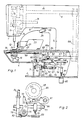
- the sewing machine has a housing (1) which consists of a carrier plate (2), a base (3), a support arm (4), a stand (5) and an arm (6) which is fitted into a head (7) expires.
- An arm shaft (8) is mounted in the arm (6) and drives a needle bar (11) via a crank (9) and a link (10).
- a thread-guiding needle (12) is fastened in the needle bar (11).
- the needle bar (11) is accommodated in a frame (13) which is displaceably mounted on a bolt (14) running parallel to the longitudinal axis of the arm (6) and is connected to a push rod (15) running parallel to it.
- the push rod (15) forms the output member of a known zigzag stitch actuator, not shown.
- Such a stitch regulator is shown and described for example in DE-PS 33 20 158.
- the needle (12) works together to form double lockstitches with a double-rotating gripper (16) which is arranged in the support arm (4) and which contains a rotating gripper body (17) and a fixed bobbin case (18).
- a throat plate (19) is arranged in the support arm (4) above the gripper (16) and has a slot-like stitch hole (20) for the passage of the needle (12).
- a workpiece holder (21) is arranged on the support arm (4) and has a lower clamp jaw (22) and an upper clamp jaw (23).
- the upper clamp jaws (23) contains a spring-loaded holding plate (24) which can be lifted off the lower clamp jaws (22) in a known manner via a roller lever (25) and an essentially vertically movable pressure plate (26).
- the feed movements of the material holder (21) and the setting of the zigzag stitch actuator are controlled by a cam, not shown, as disclosed in the aforementioned DE-PS 33 20 158.
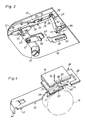
- a cutting knife (28) designed as a flat slide is displaceably arranged in a flat guide groove (27) provided on the underside of the throat plate (19) in the region of the stitch hole (20) and parallel to the circumferential plane of the gripper (16).
- the cutting knife (28) contains a rectangular recess (29), the lower boundary edge of which, according to the drawing, forms a cutting edge (30).
- the cutting knife (28) is screwed onto the throat plate (19) by two Guide pieces (31) held against falling.
- a short holding finger (35) is provided at a small lateral distance from the separating tip (34), as a result of which an incision (36) is formed between the separating tip (34) and holding finger (35), which has a groove-like shape.
- the thread catcher (33) has in its upwardly curved section a slot-like, substantially longitudinal recess (37), the end of which faces the separating tip (34) lies in the apex of the curved section, as a result of which the semicircular upper boundary edge of the recess (37) is one Forming cutting edge (38).
- the thread catcher (33) there is also a recess (39) extending obliquely in the direction of the recess (37), whereby a barb (41) is formed in connection with the longitudinal edge (40).
- the drive lever (45) is connected via a hinge pin (47) to a pull rod (48), the opposite end of which is bent downwards.
- the pull rod (48) has a longitudinal, straight guide slot (49) in the cranked section and carries a short, upwardly projecting pin (50).
- a hinge pin (51) which is fastened to the throat plate (19) and on which a flat angle lever (52) is mounted, engages in the guide slot (49).
- a control slot (53), in which the pin (50) engages, is provided in the one leg of the angle lever (52), which extends between the bent section of the pull rod (48) and the throat plate (19).
- the control slot (53) is divided into two standstill sections (54, 55) and a movement section (56) arranged between them.
- a pull rod (59) engages, the other end of which is connected to a support egg (60).
- the carrier (60) is fastened on a rotatably mounted and axially displaceable slide rod (61).
- a scanning lever (62) is attached, which has a cam follower (63).
- the scanning lever (62) interacts with a cam disk (65) which has a cam groove (66) and is fastened on a shaft (67).
- the shaft (67) is connected to the arm shaft (8) via a toothed belt gear (68).
- the scanning lever (62) is assigned an electromagnet (69) (FIG. 2) which engages on the underside of the scanning lever (62) via a pressure piece (71) arranged on the pull rod (70).
- the scanning lever (62) is also assigned a pawl (72) which has two step-shaped shoulders (73, 74) and is arranged on a shaft (75) in a rotationally fixed manner.
- a prestressed leg spring (76) arranged on the shaft (75), which is hooked on one end to a rib of the base (3) and at the other end to the pawl (72), exercises a clockwise movement corresponding to FIG. 2 on the shaft (75) Torque off.
- a three-armed lever (78) is arranged on a shaft (77) in a rotationally fixed manner.
- a shift rod (79) is articulated on one arm and has a guide slot (80) into which a pin (81) fixed to the housing engages.
- a pin (81) fixed to the housing engages.
- a pull rod (84) is articulated on another arm of the lever (78) and is connected to the pressure plate (26) via a lever mechanism (not shown) in such a way that when the lever (78 ) the pressure plate (26) is moved downward and as a result the holding plate (24) of the upper clamp jaw (23) is raised.
- An electromagnet (85) which acts on the third arm of the lever (78) via a pressure piece (87) arranged on its pull rod (86), is used to carry out the pivoting movement of the lever (78).
- a one-armed drive lever (88) is also attached to the shaft (77).
- a free shoulder (89) formed on the scanning lever (62) is assigned to the free end of the drive lever (88).
- the electromagnet (69) is acted upon, after which it moves the scanning lever (62) from the position shown in FIG. 2 pivots upwards and thereby swivels the cam follower (63) into a standstill section of the cam groove (66) which runs without an incline and is not specified in any more detail.
- the thread catcher (33) and the cutting knife (28) are in the rest position, which is at a lateral distance from the tap hole (20).
- the leg spring (76) pivots the pawl (72), based on FIG. 2, to the right, as a result of which the shoulder (74) slides under the front end of the scanning lever (62) and opens up this way ensures its position.
- the separating tip (34) penetrates into the needle thread loop formed by the gripper (16), its leg (NW) leading to the sewing material (W) and the hook thread (G) coming into contact with the longitudinal edge (40), while the needle (12) leading leg (NN) from the boundary edge of the incision (36) between the separating tip (34) and the holding finger (35) is detected.
- the needle thread loop is completely guided around the bobbin case (18) by the gripper (16) and the thread catcher (33) penetrates so far the needle thread loop until the thread leg (NW) leading to the material to be sewn (W) and the hook thread (G) slide off the longitudinal edge (40) and reach behind the barb (41) in the recess (39).
- the thread is withdrawn from the needle thread supply.
- the gripper (16) After the gripper (16) has guided the needle thread loop around the bobbin case (18), it is pulled upward by the known thread feeder, not shown, of the sewing machine, whereby it lies around the thread catcher (33) such that the needle-side loop leg (NN ) from the tap hole (20) over the incision (36) and the two recesses (39 and 37) to the cutting edge (38) and the workpiece-side loop leg (NW) from the cutting edge (38) to the tap hole (20).
- the pull rod (48) moves with the guide slot (49) relative to the fixed hinge pin (51), the pin (50) being displaced within the control slot (53).
- the position of the angle lever (52) remains unchanged and the cutting knife (28) remains in its rest position, in the cutting edge of which (30) has a lateral distance from the tap hole (20).
- the pin (50) enters the movement section (56) it causes the angle lever (52) to pivot and thus to move the cutting knife (28), this movement taking place essentially synchronously with the movement of the thread catcher (33).
- the cutting edge (30) is below the center of the tap hole (20), wherein the cutting knife (28) has reached its cutting position.
- the angle lever (52) remains unchanged in its new position, whereby the cutting knife (28) also remains in the cutting position.
- the sewing machine is stopped shortly after the top dead center of the needle movement.
- the cam follower (63) is located at the apex of the movement section (66a) which is arc-shaped in the axial direction, the thread catcher (33) and the pull rod (48) having reached their right-hand end position in relation to the drawing.
- the electromagnet (85) is acted upon, whereupon it swivels the three-armed lever (78) and the drive lever (88) in a counterclockwise direction, based on FIG. 1. Because of these pivoting movements, the pressure plate (26) is actuated via the pull rod (84) and the holding plate (24) is raised. At the same time, the shift rod (79), based on FIG. 1, is pulled to the right and the pawl (72) is pivoted back against the action of the leg spring (76) via the wedge-shaped extension (82), which interacts with the extension (83) , whereupon the leg spring (64) pivots the scanning lever (62) downward again and thereby removes the cam follower (63) from the cam groove (66). As soon as the cam follower (63) is out of engagement with the cam groove (66), the free end of the drive lever (88) rests against the shoulder (89) and then shifts the scanning lever (62) axially Direction back to the starting position shown in Fig. 1.
- the pin (50) After cutting the threads, the pin (50) enters the movement section (56) of the control slot (53) and thereby causes the angle lever (52) to be pivoted again and the cutting knife (28) to be pushed back into its rest or starting position. If the pin (50) subsequently enters the standstill section (54), the cutting knife (28) remains in the previously reached position, while the thread catcher (33) is pulled back further into its rest or starting position, in which the Separating tip (34) is completely removed from the area of the tap hole (20).
- the thread cutting device according to the invention produces thread ends of essentially the same length regardless of the overstitch position of the last stitch.
- the length of the needle thread end connected to the needle (12) remains the same respective overstitch position largely unaffected.
- the length of the needle thread end connected to the needle (12) depends on the distance of the incision (36) to the opposite boundary edge of the recess (39). The length of this thread end can be varied by appropriately designing the thread catcher (33).
Landscapes
- Engineering & Computer Science (AREA)
- Textile Engineering (AREA)
- Sewing Machines And Sewing (AREA)
Abstract
Claims (4)
- Coupe-fil pour machine à coudre à point zigzag comportant une plaque d'aiguille (19) présentant un trou d'aiguille (20), comportant une griffe (16) tournante pour double point de piqûre et un dispositif d'accrochage du fil (33), mobile en fonction de la position angulaire de l'arbre de griffe et qui comporte une pointe de séparation, un crochet pour le brin de la boucle du fil d'aiguille menant à l'étoffe à coudre et pour le fil de griffe ainsi qu'une arête de coupe (30) laquelle, coopérant avec une lame de coupe (28), sectionne les fils saisis par le crochet, caractérisé en ce que la lame de coupe (28) est déplaçable dans un plan parallèle au dispositif d'accrochage du fil (33) et est reliée, par une transmission (45 à 58) comportant des portions d'arrêt (54, 55), avec le mécanisme d'entraînement de ce dispositif, de telle sorte que la lame de coupe (28) peut passer, conjointement avec le dispositif d'accrochage de fil (33), d'une position de repos située sur le côté du trou d'aiguille (20) avec son arête tranchante (30) dans une position de coupe qui se trouve dans une zone située au-dessous du milieu de la largeur de la couture et, après séparation et sectionnement des fils, peut retourner dans la position de repos, conjointement avec le dispositif d'accrochage de fil (33), sous l'effet de la poursuite du déplacement de ce dernier, après amenée de la lame de coupe (28) dans la position de coupe.
- Coupe-fil selon la revendication 1, caractérisé en ce que la transmission (45 à 58) pour la lame de coupe (28) est conçue sur le principe de la concordance des formes.
- Coupe-fil selon les revendications 1 et 2, caractérisé en ce que le dispositif d'accrochage de fil (33) et la lame de coupe (28) sont placés et guidés sur la plaque d'aiguille (19), par des moyens (31) communs et en ce qu'un levier d'entraînement (45) du dispositif d'accrochage de fil (33) est relié, par un tirant (48), à un levier coudé (52) monté sur la plaque d'aiguille (19), par un doigt d'articulation (51), ce dernier s'engageant dans une fente de guidage (49) du tirant (48) et un doigt (50), fixé sur le tirant (48), s'engageant dans une fente de commande (53) du levier coudé (52) et en ce que le levier coudé (52) s'articule sur la lame de coupe (28), par un assemblage à trou allongé et doigt (57, 58).
- Coupe-fil selon une ou plusieurs des revendications 1 à 3, caractérisé en ce que le dispositif d'accrochage de fil (33) comporte, sur le côté opposé au crochet (41), à une distance latérale de la pointe de séparation (34), un doigt de retenue (35) pour le brin (NN) de la boucle de fil d'aiguille, menant à l'aiguille (12).
Applications Claiming Priority (2)
| Application Number | Priority Date | Filing Date | Title |
|---|---|---|---|
| DE3715603 | 1987-05-09 | ||
| DE3715603A DE3715603C1 (de) | 1987-05-09 | 1987-05-09 | Fadenschneidvorrichtung fuer Zickzack-Naehmaschinen |
Publications (2)
| Publication Number | Publication Date |
|---|---|
| EP0348436A1 EP0348436A1 (fr) | 1990-01-03 |
| EP0348436B1 true EP0348436B1 (fr) | 1992-09-30 |
Family
ID=6327241
Family Applications (1)
| Application Number | Title | Priority Date | Filing Date |
|---|---|---|---|
| EP88903802A Expired - Lifetime EP0348436B1 (fr) | 1987-05-09 | 1988-04-19 | Coupe-fil pour machines a coudre a point zig-zag |
Country Status (8)
| Country | Link |
|---|---|
| US (1) | US5005504A (fr) |
| EP (1) | EP0348436B1 (fr) |
| JP (1) | JP2912374B2 (fr) |
| KR (1) | KR950012454B1 (fr) |
| BR (1) | BR8807499A (fr) |
| DE (1) | DE3715603C1 (fr) |
| ES (1) | ES2007485A6 (fr) |
| WO (1) | WO1988008894A1 (fr) |
Families Citing this family (14)
| Publication number | Priority date | Publication date | Assignee | Title |
|---|---|---|---|---|
| DE4132991C1 (en) * | 1991-10-04 | 1992-12-03 | Duerkopp Adler Ag, 4800 Bielefeld, De | Producing seam having short thread ends on bottom of workpiece - involves drawing back needle thread from underside of workpiece so that only short thread piece remains on underside |
| US5333565A (en) * | 1992-10-30 | 1994-08-02 | Mim Industries, Inc. | Thread cutting via reciprocating arm with pockets and a trimming plate |
| US5289791A (en) * | 1993-03-31 | 1994-03-01 | General Motors Corporation | Sewing machine with thread wiper and auxiliary cutter |
| DE4323494C1 (de) * | 1993-07-14 | 1994-08-18 | Union Special Gmbh | Fadentrenneinrichtung für eine Zylinderarm-Kettenstichnähmaschine |
| JP2880406B2 (ja) * | 1994-06-29 | 1999-04-12 | ジューキ株式会社 | ミシンの下糸端保持装置 |
| US6062152A (en) * | 1998-05-12 | 2000-05-16 | Capital Automation Co., Ltd. | Automatic thread cutting device for an embroidery machine |
| JP4245222B2 (ja) * | 1999-03-24 | 2009-03-25 | Juki株式会社 | ミシンの下糸切断装置 |
| CN100350091C (zh) * | 2003-12-08 | 2007-11-21 | 星锐缝纫机股份有限公司 | 横式直筒缝纫机 |
| US6968793B2 (en) * | 2003-12-15 | 2005-11-29 | Shing Ray Sewing Machine Co., Ltd. | Transverse longitudinal-cylinder sewing machine |
| US6904854B1 (en) * | 2003-12-15 | 2005-06-14 | Shing Ray Sewing Machine Co., Ltd. | Transverse longitudinal-cylinder sewing machine |
| JP2006102399A (ja) * | 2004-10-08 | 2006-04-20 | Juki Corp | ミシン |
| JP5115226B2 (ja) * | 2008-02-07 | 2013-01-09 | ブラザー工業株式会社 | ミシンの糸切り装置 |
| CH704524A1 (de) * | 2011-02-28 | 2012-08-31 | Bernina Int Ag | Verfahren zum Schneiden des Unter- und mindestens eines Oberfadens und ein Verfahren zum Ansticken sowie eine Vorrichtung zur Durchführung der Verfahren. |
| DE102021128687A1 (de) | 2021-11-04 | 2023-05-04 | Bundesdruckerei Gmbh | Klemmvorrichtung für einen Hinter- oder Unterfaden einer Nähmaschine |
Family Cites Families (18)
| Publication number | Priority date | Publication date | Assignee | Title |
|---|---|---|---|---|
| DE155166C (fr) * | 1901-01-31 | |||
| US2376417A (en) * | 1944-06-13 | 1945-05-22 | Chudner Joseph | Thread cutter |
| US2968269A (en) * | 1959-06-24 | 1961-01-17 | Singer Mfg Co | Thread cutting mechanisms for sewing machines |
| FR1284956A (fr) * | 1960-04-04 | 1962-02-16 | Pfaff Ag G M | Procédé pour la coupe du fil supérieur et du fil inférieur, dans les machines à coudre à point de navette, et dispositif pour la mise en oeuvre de ce procédé |
| US3413944A (en) * | 1965-10-01 | 1968-12-03 | American Safety Table Co | Thread severing attachment for sewing machine |
| ES354872A1 (es) * | 1967-07-07 | 1969-11-16 | Rimoldi C Spa Virginio | Dispositivo para cortar contemporaneamente los hilos de co-sido de una maquina de coser. |
| US3602170A (en) * | 1969-03-24 | 1971-08-31 | Aisin Seiki | Thread cutter in sewing machine |
| DE1941794A1 (de) * | 1969-08-16 | 1971-03-18 | Pfaff Ag G M | Fadenschneideinrichtung an Doppelsteppstichnaehmaschinen |
| DE2124646A1 (de) * | 1970-05-20 | 1971-12-02 | Csepeli Kerekpar es Varrogepgyar, Budapest | Fadentrennvorrichtung für Häkelstich-Nähmaschinen |
| US3701329A (en) * | 1971-01-04 | 1972-10-31 | Honeywell Inf Systems | Stitch control mechanisms and thread cutter |
| US3709176A (en) * | 1971-10-08 | 1973-01-09 | Singer Co | Underbed thread trimming mechanism for sewing machines |
| SU400639A1 (ru) * | 1971-12-24 | 1973-10-01 | Подольский ордена Ленина , ордена Трудового Красного Знамени механический завод М. И. Калинина | Приспособление для обрезки нитей игл и петлителя на плоскошовной швейной машине |
| US4365568A (en) * | 1980-05-15 | 1982-12-28 | The Singer Company | Underbed thread trimmer and controlled single-operation cam mechanism therefor |
| DE3124795C1 (de) * | 1981-06-24 | 1982-11-04 | Pfaff Industriemaschinen Gmbh, 6750 Kaiserslautern | Fadenabschneidvorrichtung fuer Zickzack-Naehmaschinen |
| DE3320158C2 (de) * | 1983-06-03 | 1985-04-04 | Pfaff Industriemaschinen Gmbh, 6750 Kaiserslautern | Vorschubantrieb für eine Stichgruppennähmaschine |
| JPS6168084A (ja) * | 1984-09-10 | 1986-04-08 | ブラザー工業株式会社 | ミシンの糸切り装置 |
| US4566395A (en) * | 1984-11-05 | 1986-01-28 | Clinton Industries, Inc. | Sewing machine needle thread capturing and severing mechanism |
| JPS62298393A (ja) * | 1986-06-19 | 1987-12-25 | ペガサスミシン製造株式会社 | シリンダ−ミシンの糸切断装置 |
-
1987
- 1987-05-09 DE DE3715603A patent/DE3715603C1/de not_active Expired
-
1988
- 1988-04-19 US US07/438,438 patent/US5005504A/en not_active Expired - Fee Related
- 1988-04-19 JP JP63503661A patent/JP2912374B2/ja not_active Expired - Lifetime
- 1988-04-19 KR KR1019880701772A patent/KR950012454B1/ko not_active IP Right Cessation
- 1988-04-19 EP EP88903802A patent/EP0348436B1/fr not_active Expired - Lifetime
- 1988-04-19 BR BR888807499A patent/BR8807499A/pt unknown
- 1988-04-19 WO PCT/EP1988/000329 patent/WO1988008894A1/fr active IP Right Grant
- 1988-04-29 ES ES8801316A patent/ES2007485A6/es not_active Expired
Also Published As
| Publication number | Publication date |
|---|---|
| BR8807499A (pt) | 1990-05-08 |
| WO1988008894A1 (fr) | 1988-11-17 |
| EP0348436A1 (fr) | 1990-01-03 |
| JP2912374B2 (ja) | 1999-06-28 |
| KR890700708A (ko) | 1989-04-26 |
| DE3715603C1 (de) | 1988-06-23 |
| ES2007485A6 (es) | 1989-06-16 |
| KR950012454B1 (ko) | 1995-10-18 |
| JPH02503389A (ja) | 1990-10-18 |
| US5005504A (en) | 1991-04-09 |
Similar Documents
| Publication | Publication Date | Title |
|---|---|---|
| DE102007045598B4 (de) | Nähmaschine | |
| DE19722395C1 (de) | Nähmaschine mit einer Fadenschneideinrichtung | |
| EP0348436B1 (fr) | Coupe-fil pour machines a coudre a point zig-zag | |
| DE1125742B (de) | Fadenabschneideeinrichtung an Naehmaschinen | |
| DE3116931C2 (de) | Vorrichtung an Nähmaschinen zum Ausziehen und Abschneiden der Fäden | |
| DE19611793B4 (de) | Fadenschneider für eine Kettenstich-Nähmaschine | |
| DE1760703A1 (de) | Vorrichtung zum gleichzeitigen Schneiden der Naehfaeden in einer Naehmaschine | |
| DE19746653C1 (de) | Verfahren zum Verkürzen des nähgutseitigen Greiferfadenendes bei Nähmaschinen mit Fadenschneideinrichtung | |
| EP2300654B1 (fr) | Procédé et dispositif de séparation du fil d'aiguille et du fil de navette de machines à coudre à double point noué et à navette tournant dans un plan horizontal | |
| DE3812129A1 (de) | Vorrichtung zum positionieren einer fadenkette | |
| DE836877C (de) | Naehmaschine | |
| DE2123601C3 (de) | Fadensteuervorrichtung für eine Nähmaschine | |
| DE3143816A1 (de) | Nadelschutz fuer zweinadelnaehmaschinen | |
| DE4118008C2 (fr) | ||
| DE1060228B (de) | Einfaden-Kettenstichnaehmaschine | |
| DE1146342B (de) | Naehmaschine mit einer Fadenschneid- und -einklemmvorrichtung | |
| DE827444C (de) | Fadentrenneinrichtung fuer Naehmaschinen | |
| DE2212338B2 (de) | Festhaltevorrichtung bei einem Knoter, insbesondere an Spinnmaschinen | |
| DE2923570C2 (de) | Doppelkettenstich-Nähmaschine | |
| DE2013581A1 (de) | Fadenabschneideeinrichtung an Doppelkettenstich-Nähmaschinen | |
| DE2743727C3 (de) | Vorrichtung zum Abschneiden des Nadel- und Spulenfadens an einer automatischen Nähmaschine | |
| DE829253C (de) | Fadenabzugs- und -schneidvorrichtung fuer Naehmaschinen | |
| DE1921271A1 (de) | Buchheftmaschine und Verfahren zum Heften von Buechern | |
| DE2207366C3 (de) | Antrieb für Fadenzieher und Fadenwischer an einer Nähmaschine | |
| DE145264C (fr) |
Legal Events
| Date | Code | Title | Description |
|---|---|---|---|
| PUAI | Public reference made under article 153(3) epc to a published international application that has entered the european phase |
Free format text: ORIGINAL CODE: 0009012 |
|
| 17P | Request for examination filed |
Effective date: 19890215 |
|
| AK | Designated contracting states |
Kind code of ref document: A1 Designated state(s): IT |
|
| 17Q | First examination report despatched |
Effective date: 19910925 |
|
| RAP1 | Party data changed (applicant data changed or rights of an application transferred) |
Owner name: G.M. PFAFF AKTIENGESELLSCHAFT |
|
| GRAA | (expected) grant |
Free format text: ORIGINAL CODE: 0009210 |
|
| AK | Designated contracting states |
Kind code of ref document: B1 Designated state(s): IT |
|
| ITF | It: translation for a ep patent filed |
Owner name: JACOBACCI & PERANI S.P.A. |
|
| PLBE | No opposition filed within time limit |
Free format text: ORIGINAL CODE: 0009261 |
|
| STAA | Information on the status of an ep patent application or granted ep patent |
Free format text: STATUS: NO OPPOSITION FILED WITHIN TIME LIMIT |
|
| 26N | No opposition filed | ||
| PG25 | Lapsed in a contracting state [announced via postgrant information from national office to epo] |
Ref country code: IT Free format text: LAPSE BECAUSE OF NON-PAYMENT OF DUE FEES Effective date: 20050419 |