EP0285139B1 - Bilderzeugungsgerät - Google Patents
Bilderzeugungsgerät Download PDFInfo
- Publication number
- EP0285139B1 EP0285139B1 EP88105190A EP88105190A EP0285139B1 EP 0285139 B1 EP0285139 B1 EP 0285139B1 EP 88105190 A EP88105190 A EP 88105190A EP 88105190 A EP88105190 A EP 88105190A EP 0285139 B1 EP0285139 B1 EP 0285139B1
- Authority
- EP
- European Patent Office
- Prior art keywords
- conveying
- image forming
- recording material
- sheet
- roller
- Prior art date
- Legal status (The legal status is an assumption and is not a legal conclusion. Google has not performed a legal analysis and makes no representation as to the accuracy of the status listed.)
- Expired - Lifetime
Links
Images


Classifications
-
- G—PHYSICS
- G03—PHOTOGRAPHY; CINEMATOGRAPHY; ANALOGOUS TECHNIQUES USING WAVES OTHER THAN OPTICAL WAVES; ELECTROGRAPHY; HOLOGRAPHY
- G03G—ELECTROGRAPHY; ELECTROPHOTOGRAPHY; MAGNETOGRAPHY
- G03G21/00—Arrangements not provided for by groups G03G13/00 - G03G19/00, e.g. cleaning, elimination of residual charge
- G03G21/16—Mechanical means for facilitating the maintenance of the apparatus, e.g. modular arrangements
- G03G21/18—Mechanical means for facilitating the maintenance of the apparatus, e.g. modular arrangements using a processing cartridge, whereby the process cartridge comprises at least two image processing means in a single unit
- G03G21/1839—Means for handling the process cartridge in the apparatus body
- G03G21/1842—Means for handling the process cartridge in the apparatus body for guiding and mounting the process cartridge, positioning, alignment, locks
- G03G21/1853—Means for handling the process cartridge in the apparatus body for guiding and mounting the process cartridge, positioning, alignment, locks the process cartridge being mounted perpendicular to the axis of the photosensitive member
-
- G—PHYSICS
- G03—PHOTOGRAPHY; CINEMATOGRAPHY; ANALOGOUS TECHNIQUES USING WAVES OTHER THAN OPTICAL WAVES; ELECTROGRAPHY; HOLOGRAPHY
- G03G—ELECTROGRAPHY; ELECTROPHOTOGRAPHY; MAGNETOGRAPHY
- G03G15/00—Apparatus for electrographic processes using a charge pattern
- G03G15/14—Apparatus for electrographic processes using a charge pattern for transferring a pattern to a second base
- G03G15/16—Apparatus for electrographic processes using a charge pattern for transferring a pattern to a second base of a toner pattern, e.g. a powder pattern, e.g. magnetic transfer
- G03G15/1665—Apparatus for electrographic processes using a charge pattern for transferring a pattern to a second base of a toner pattern, e.g. a powder pattern, e.g. magnetic transfer by introducing the second base in the nip formed by the recording member and at least one transfer member, e.g. in combination with bias or heat
- G03G15/167—Apparatus for electrographic processes using a charge pattern for transferring a pattern to a second base of a toner pattern, e.g. a powder pattern, e.g. magnetic transfer by introducing the second base in the nip formed by the recording member and at least one transfer member, e.g. in combination with bias or heat at least one of the recording member or the transfer member being rotatable during the transfer
-
- G—PHYSICS
- G03—PHOTOGRAPHY; CINEMATOGRAPHY; ANALOGOUS TECHNIQUES USING WAVES OTHER THAN OPTICAL WAVES; ELECTROGRAPHY; HOLOGRAPHY
- G03G—ELECTROGRAPHY; ELECTROPHOTOGRAPHY; MAGNETOGRAPHY
- G03G15/00—Apparatus for electrographic processes using a charge pattern
- G03G15/65—Apparatus which relate to the handling of copy material
-
- G—PHYSICS
- G03—PHOTOGRAPHY; CINEMATOGRAPHY; ANALOGOUS TECHNIQUES USING WAVES OTHER THAN OPTICAL WAVES; ELECTROGRAPHY; HOLOGRAPHY
- G03G—ELECTROGRAPHY; ELECTROPHOTOGRAPHY; MAGNETOGRAPHY
- G03G21/00—Arrangements not provided for by groups G03G13/00 - G03G19/00, e.g. cleaning, elimination of residual charge
- G03G21/16—Mechanical means for facilitating the maintenance of the apparatus, e.g. modular arrangements
- G03G21/1604—Arrangement or disposition of the entire apparatus
- G03G21/1623—Means to access the interior of the apparatus
- G03G21/1638—Means to access the interior of the apparatus directed to paper handling or jam treatment
-
- G—PHYSICS
- G03—PHOTOGRAPHY; CINEMATOGRAPHY; ANALOGOUS TECHNIQUES USING WAVES OTHER THAN OPTICAL WAVES; ELECTROGRAPHY; HOLOGRAPHY
- G03G—ELECTROGRAPHY; ELECTROPHOTOGRAPHY; MAGNETOGRAPHY
- G03G21/00—Arrangements not provided for by groups G03G13/00 - G03G19/00, e.g. cleaning, elimination of residual charge
- G03G21/16—Mechanical means for facilitating the maintenance of the apparatus, e.g. modular arrangements
- G03G21/1661—Mechanical means for facilitating the maintenance of the apparatus, e.g. modular arrangements means for handling parts of the apparatus in the apparatus
- G03G21/1695—Mechanical means for facilitating the maintenance of the apparatus, e.g. modular arrangements means for handling parts of the apparatus in the apparatus for paper transport
-
- G—PHYSICS
- G03—PHOTOGRAPHY; CINEMATOGRAPHY; ANALOGOUS TECHNIQUES USING WAVES OTHER THAN OPTICAL WAVES; ELECTROGRAPHY; HOLOGRAPHY
- G03G—ELECTROGRAPHY; ELECTROPHOTOGRAPHY; MAGNETOGRAPHY
- G03G2215/00—Apparatus for electrophotographic processes
- G03G2215/00362—Apparatus for electrophotographic processes relating to the copy medium handling
- G03G2215/00367—The feeding path segment where particular handling of the copy medium occurs, segments being adjacent and non-overlapping. Each segment is identified by the most downstream point in the segment, so that for instance the segment labelled "Fixing device" is referring to the path between the "Transfer device" and the "Fixing device"
- G03G2215/00371—General use over the entire feeding path
-
- G—PHYSICS
- G03—PHOTOGRAPHY; CINEMATOGRAPHY; ANALOGOUS TECHNIQUES USING WAVES OTHER THAN OPTICAL WAVES; ELECTROGRAPHY; HOLOGRAPHY
- G03G—ELECTROGRAPHY; ELECTROPHOTOGRAPHY; MAGNETOGRAPHY
- G03G2215/00—Apparatus for electrophotographic processes
- G03G2215/00362—Apparatus for electrophotographic processes relating to the copy medium handling
- G03G2215/00367—The feeding path segment where particular handling of the copy medium occurs, segments being adjacent and non-overlapping. Each segment is identified by the most downstream point in the segment, so that for instance the segment labelled "Fixing device" is referring to the path between the "Transfer device" and the "Fixing device"
- G03G2215/00379—Copy medium holder
- G03G2215/00392—Manual input tray
-
- G—PHYSICS
- G03—PHOTOGRAPHY; CINEMATOGRAPHY; ANALOGOUS TECHNIQUES USING WAVES OTHER THAN OPTICAL WAVES; ELECTROGRAPHY; HOLOGRAPHY
- G03G—ELECTROGRAPHY; ELECTROPHOTOGRAPHY; MAGNETOGRAPHY
- G03G2215/00—Apparatus for electrophotographic processes
- G03G2215/00362—Apparatus for electrophotographic processes relating to the copy medium handling
- G03G2215/00367—The feeding path segment where particular handling of the copy medium occurs, segments being adjacent and non-overlapping. Each segment is identified by the most downstream point in the segment, so that for instance the segment labelled "Fixing device" is referring to the path between the "Transfer device" and the "Fixing device"
- G03G2215/00417—Post-fixing device
- G03G2215/00421—Discharging tray, e.g. devices stabilising the quality of the copy medium, postfixing-treatment, inverting, sorting
-
- G—PHYSICS
- G03—PHOTOGRAPHY; CINEMATOGRAPHY; ANALOGOUS TECHNIQUES USING WAVES OTHER THAN OPTICAL WAVES; ELECTROGRAPHY; HOLOGRAPHY
- G03G—ELECTROGRAPHY; ELECTROPHOTOGRAPHY; MAGNETOGRAPHY
- G03G2215/00—Apparatus for electrophotographic processes
- G03G2215/00362—Apparatus for electrophotographic processes relating to the copy medium handling
- G03G2215/00535—Stable handling of copy medium
- G03G2215/00544—Openable part of feed path
-
- G—PHYSICS
- G03—PHOTOGRAPHY; CINEMATOGRAPHY; ANALOGOUS TECHNIQUES USING WAVES OTHER THAN OPTICAL WAVES; ELECTROGRAPHY; HOLOGRAPHY
- G03G—ELECTROGRAPHY; ELECTROPHOTOGRAPHY; MAGNETOGRAPHY
- G03G2221/00—Processes not provided for by group G03G2215/00, e.g. cleaning or residual charge elimination
- G03G2221/16—Mechanical means for facilitating the maintenance of the apparatus, e.g. modular arrangements and complete machine concepts
- G03G2221/1636—Mechanical means for facilitating the maintenance of the apparatus, e.g. modular arrangements and complete machine concepts for the exposure unit
-
- G—PHYSICS
- G03—PHOTOGRAPHY; CINEMATOGRAPHY; ANALOGOUS TECHNIQUES USING WAVES OTHER THAN OPTICAL WAVES; ELECTROGRAPHY; HOLOGRAPHY
- G03G—ELECTROGRAPHY; ELECTROPHOTOGRAPHY; MAGNETOGRAPHY
- G03G2221/00—Processes not provided for by group G03G2215/00, e.g. cleaning or residual charge elimination
- G03G2221/16—Mechanical means for facilitating the maintenance of the apparatus, e.g. modular arrangements and complete machine concepts
- G03G2221/1651—Mechanical means for facilitating the maintenance of the apparatus, e.g. modular arrangements and complete machine concepts for connecting the different parts
- G03G2221/1654—Locks and means for positioning or alignment
-
- G—PHYSICS
- G03—PHOTOGRAPHY; CINEMATOGRAPHY; ANALOGOUS TECHNIQUES USING WAVES OTHER THAN OPTICAL WAVES; ELECTROGRAPHY; HOLOGRAPHY
- G03G—ELECTROGRAPHY; ELECTROPHOTOGRAPHY; MAGNETOGRAPHY
- G03G2221/00—Processes not provided for by group G03G2215/00, e.g. cleaning or residual charge elimination
- G03G2221/16—Mechanical means for facilitating the maintenance of the apparatus, e.g. modular arrangements and complete machine concepts
- G03G2221/1651—Mechanical means for facilitating the maintenance of the apparatus, e.g. modular arrangements and complete machine concepts for connecting the different parts
- G03G2221/1657—Mechanical means for facilitating the maintenance of the apparatus, e.g. modular arrangements and complete machine concepts for connecting the different parts transmitting mechanical drive power
-
- G—PHYSICS
- G03—PHOTOGRAPHY; CINEMATOGRAPHY; ANALOGOUS TECHNIQUES USING WAVES OTHER THAN OPTICAL WAVES; ELECTROGRAPHY; HOLOGRAPHY
- G03G—ELECTROGRAPHY; ELECTROPHOTOGRAPHY; MAGNETOGRAPHY
- G03G2221/00—Processes not provided for by group G03G2215/00, e.g. cleaning or residual charge elimination
- G03G2221/16—Mechanical means for facilitating the maintenance of the apparatus, e.g. modular arrangements and complete machine concepts
- G03G2221/1672—Paper handling
- G03G2221/1675—Paper handling jam treatment
-
- G—PHYSICS
- G03—PHOTOGRAPHY; CINEMATOGRAPHY; ANALOGOUS TECHNIQUES USING WAVES OTHER THAN OPTICAL WAVES; ELECTROGRAPHY; HOLOGRAPHY
- G03G—ELECTROGRAPHY; ELECTROPHOTOGRAPHY; MAGNETOGRAPHY
- G03G2221/00—Processes not provided for by group G03G2215/00, e.g. cleaning or residual charge elimination
- G03G2221/16—Mechanical means for facilitating the maintenance of the apparatus, e.g. modular arrangements and complete machine concepts
- G03G2221/1678—Frame structures
- G03G2221/1687—Frame structures using opening shell type machines, e.g. pivoting assemblies
-
- G—PHYSICS
- G03—PHOTOGRAPHY; CINEMATOGRAPHY; ANALOGOUS TECHNIQUES USING WAVES OTHER THAN OPTICAL WAVES; ELECTROGRAPHY; HOLOGRAPHY
- G03G—ELECTROGRAPHY; ELECTROPHOTOGRAPHY; MAGNETOGRAPHY
- G03G2221/00—Processes not provided for by group G03G2215/00, e.g. cleaning or residual charge elimination
- G03G2221/16—Mechanical means for facilitating the maintenance of the apparatus, e.g. modular arrangements and complete machine concepts
- G03G2221/18—Cartridge systems
Definitions
- the present invention relates to an image forming apparatus according to the preamble of claim 1.
- a copying machine or a laser beam printer or the like which uses an electrophotographic process for image formation, is constructed such that a part of an image forming means or an entire major part of an image forming means (cartridge) as in a personal use copying machine, is taken out of a main assembly of the image forming apparatus to perform maintenance and exchanging operations, more particularly to replenish developer or to exchange a photosensitive drum having a limited service life.
- the image forming apparatus is provided with a transfer material passage for conveying the transfer material in the apparatus to the image forming apparatus, and for discharging it outside the apparatus after the image formation, the transfer material conveying passage is made openable so as to facilitate for the operator to remove a jammed sheet.
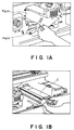
- FIG. 1A there is shown an example of a conventional structure wherein an operator opens a front cover, moves a part of the conveying passage Path from an image forming means such as a photosensitive drum; and then, the operator is able to access the opened space to take the jammed paper Pjam.
- an image forming means such as a photosensitive drum
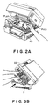
- FIG. 2A there is shown another example wherein the conveying passage Path is fixed to a bottom portion AB of the main assembly, wherein an operator moves upwardly an image forming means including a photosensitive drum or the like to open the conveying passage so as to facilitate for the operator to take the jammed paper Pjam out.
- This is called bivalve type.
- FIG. 2B another example is shown which is used in a small size apparatus having a low process speed not more than 10 copies per minutes, wherein an upper unit AA containing an image forming means is moved upwardly, and then a process cartridge C containing a cleaning means, a charger, a developing device and another charger constituting the image forming means is taken out from the front side of the apparatus for the purpose of maintenance or exchange.
- Figure 1B shows another example, wherein similarly to Figure 1A, the front cover is opened, and then a cartridge C is removed.
- the structure of the first example involves a problem that since the conveying passage is opened within the apparatus, the operator is required to insert his hand through the opening provided in the front plate to take the jammed sheet out of the apparatus, so that it is difficult to remove the jammed sheet.
- the image forming means is taken out through the front side opening, and therefore, the front plate is required to have a relatively large opening which is disadvantageous from the standpoint of the mechanical strength and production of vibration.
- FIG. 2A and 2B involves a problem that the upper unit is more easily influenced by vibration than the lower unit containing the conveying passage and heavy elements such as power source or the like, since the upper unit containing the image forming means such as a photosensitive drum is moved upwardly. Additionally, it is not possible to increase the weight of the upper unit, and the vibration of the image forming means leads to a degraded quality of images, such as blurred image.
- the image forming means is constructed by many precision parts, and therefore, movement of the upper unit can result in an impact influential to those parts.
- An apparatus according to the preamble of claim 1 is known from JP-A-59 112 542, for example.
- a conveying means arranged separate from the main assembly is disposed in a manner to be removable on rails by means of a longitudinal sliding motion. If a paper jam occurs in this apparatus, the conveying means can be drawn out horizontally and the paper conveying passage within the main assembly can be exposed. However, in JP-A-59 112 542 the arrangement is such that the exposed conveying passage is not freely accessible from the top since the main assembly housing projects over the conveying passage.
- JP-A-59 77 450 From JP-A-59 77 450 is it known to separate the conveying unit from the main assembly by rotation in a downward direction.
- the arrangement is such that the exposed conveying passage is not freely accessible since the lower parts of the narrow V-shaped opening between the main assembly and the conveying unit are deeply inside the apparatus.
- a part (top wall) of the main assembly is arranged at the side of the conveying unit and interferes with an operators hand, which would grab into the narrow V-shaped opening.
- a sheet supplying inlet and a sheet discharging outlet are located on the same side of the apparatus.
- the conveying means is opened at one of vertical sides, by which another unit such as an image scanner can be disposed on the top of the apparatus, and in addition, the installing area of the entire system can be reduced.
- a part or an entirety of the image forming means can be removed from the apparatus in a direction in which a conveying means for conveying a transfer material to the image forming means is opened, and then the necessary part is exchanged.
- the jam clearance operation and the maintenance operation for the image forming means can be performed in the same direction.
- the apparatus can be opened large upon jam clearance operation.
- the large opening can be used for exchange and maintenance of the image forming means, and the space can be used efficiently. Therefore, the operativeness is not degraded even when the size of the apparatus is reduced.
- the directions of the supply and discharge of the transfer material, the opening for the jam clearance operation and the opening for the maintenance operation can be made all the same, whereby the area required for the installment can be reduced.
- Figures 1A and 1B are perspective views illustrating jam clearance operation in conventional machines.
- Figures 2A and 2B are perspective views illustrating jam clearance operation in other conventional machines.
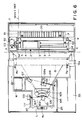
- Figure 3 is a sectional view of a laser beam printer according to the present invention.
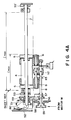
- FIGS 4A, 4B and 4C illustrate detailed structure of sheet conveying means in the laser beam printer of Figure 3.
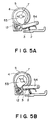
- Figures 5A and 5B are sectional views of sheet supplying means of the laser beam printer of Figure 3.
- Figure 6 is a top plan view of the laser beam printer of Figure 3.
- Figure 7 is a sectional view of a part of the laser beam printer of Figure 3.
- Figure 8 illustrates mounting and dismounting of a part for the maintenance operation.
- Figures 9A and 9B show another embodiment, wherein a sheet conveying portion is illustrated.
- FIG. 3 there is shown a laser beam printer as an exemplary image forming apparatus according to a first embodiment of the present invention.
- a number of the transfer materials in the form of cut sheets P are stacked on a sheet feeding tray 1.
- a stacking plate 3 for stacking the cut sheets P which is pivotable by the urging force provided by a spring 2 urges the leading edge portion of the stacked sheets P to a feeding roller 4 and an idler roller 5.
- the feeding roller 4 is provided with a portion having a smaller diameter than the other portion, and the configuration thereof is such that it can take at least one position (initializing position) in which it does not contacted to the cut sheet P and a conveying roller 6.
- the idler rollers 5 are disposed adjacent opposite ends of the feeding roller 4 and are smoothly rotatable about a feeding roller shaft 7.
- the idler rollers 5 have an outer diameter which is slightly smaller than the maximum diameter of the feeding roller 4.
- the overall length of the roller arrangement including the feeding roller and the idler rollers 5 is smaller than the minimum width l min of the smallest sheets usable with the apparatus, and the effective portions of the feeding roller (large diameter portion) may be divided into two parts as in this embodiment.
- the feeding roller 4 is fixed to the driving shaft 7 which is controlled for one turn rotation by a spring clutch 51 and the solenoid 52 adjacent an end thereof.
- cams 53 and 53′ for pivotting the stacking plate 3 is mounted to the shaft.
- cam followers 54 and 54′ are fixedly mounted on the stacking plate 3, so that the stacking plate 3 is pivoted upwardly and downwardly in response to rotation of the driving shaft 7 to selectively urge the topmost cut sheet P to the feeding roller 4 and the idler rollers 5.
- the stacking plate 3 takes its lower position as shown in Figures 3 and 5A, and therefore, the cut sheets can be smoothly loaded.
- the conveying roller 6 is pivotable by a swinging arm 9 about a drive input shaft 8 and is normally urged to the feeding roller 4 and the idler rollers 5 by a spring 11 stretched between itself and the apparatus base 10.
- the driving force to the conveying roller 6 is transmitted by a driving gear 112 fixed to the drive input shaft and a conveying gear 113 fixed to the conveying roller 6.
- the driving gear 112 and the conveying gear 113 are disposed adjacent the center of the length of the conveying roller 6, and therefore, the conveying roller 6 is not unbalanced by the application of the driving force to provide a stable contact therebetween.
- a separating pad 12 is press-contacted to the feeding roller 4 and the idler rollers 5.
- the separating pad 12 functions as a friction member pivotably supported at its intermediate position, and is spring-urged at the intermediate position with equalization.
- the separating pad 12 is of rubber material containing cork.
- the separating pad 12 is effective to separate the cut sheets.
- the conveying passage, other than the separating pads, is formed by the guiding portion 10a which is formed by the apparatus base 10.
- the base 10 is provided with a second cut sheet inlet 10b for receiving a sheet from other than the feeding tray 1. The sheet fed through this inlet 10b is introduced into the nip N formed between the conveying roller 6 and the idler rollers 5.
- the stacking plate takes its lower position by being urged by the cams 53 and 53′ and the cam followers 54 and 54′, and therefore, the cut sheet P is not contacted to the idler rollers 5.
- a conveying drive gear 55 By rotation of a conveying drive gear 55, the driving force is transmitted to the driving gear 56 fixed to the drive input shaft 8, and to a coupler gear 58 meshed with the driving gear 56 and rotatably mounted on a coupler arm 57 swingable about the drive input shaft 8.
- the coupler gear 58 is provided with a flange, which is contacted to a flange of a sheet feed drive gear 59 constituting the spring clutch 51, so as to compensate backlash.
- the elements including and upstream of the coupler gear 58 from the motor with respect to the drive transmission, are mounted to the base 10 of the main assembly of the apparatus.
- the feed drive gear 59 is mounted on a feed roller shaft 7, which is mounted to an outer cover K containing an image fixing station. Therefore, by the mounting and dismounting of the outer cover K, the drive transmission is engaged or disengaged.
- the rotation of the feed drive gear 59 is transmitted to a feed roller shaft 7 through a spring clutch 51.
- the spring clutch 51 when the solenoid 52 is not energized (off), does not transmit the driving force of the feed drive gear 59 to the feeding roller shaft 7, since a pawl 52a of the solenoid 52 is engaged with a pawl 60a of a control ring 60 of the spring clutch.
- the solenoid 52 is energized (on)
- the pawl 52a of the solenoid 52 is disengaged from the pawl 60a of the control ring 60, and therefore, the driving force of the feed drive gear 59 is transmitted to the feed roller shaft.
- One turn of the feeding roller shaft 1 is controlled in this manner.
- the cut sheet P reaches the separating pad 12 portion where only the topmost sheet P is advanced downstream due to the set relationship between the frictional coefficient sooner or later, the cut sheet P reaches the nip N formed between the idler rollers 5 and the conveying roller 5 being driven, whereafter the cut sheet is conveyed by the conveying roller 6 at a stabilized speed.
- a sensor lever 13 Downstream of the nip N formed between the conveying roller 6 and the idler rollers 5, there is disposed a sensor lever 13 which is rotatably supported on the swingable arm 9 and which serves to detect a leading edge of the cut sheet P with the aid of a photointerruptor 14.
- the sheet sensing mechanism in this embodiment is constituted by the sensor lever 13 and the photointerruptor 14, as shown in the Figure, but this is not limiting, and a sensor of a transparent type or a reflection type may be used.
- the sheet P is guided to the photosensitive drum 15 by guides 16a in the form of ribs into which a part of a casing 16 for the developing device D is formed, so that the sheet P can be conveyed accurately with low cost and easy manufacturing.
- a toner image formed on the photosensitive drum 15 through an image forming process which will be described hereinafter is transferred onto a transfer material by a transfer roller 17 which is pressed to the photosensitive drum 15 under a total pressure of 300 - 1000 g and which is driven by a gear 15a disposed adjacent a longitudinal end of the photosensitive drum 15 or which rotates following the photosensitive drum 15.
- the transfer roller 17 is made of a semiconductive rubber roller having a volume resistivity of 102 - 105 ohm.cm. During the transferring operation, the transfer roller 17 is supplied with a bias of DC 500 V - 1500 V having a polarity opposite to that of the toner.
- the toner image is transferred onto the cut sheet P (transfer material) from the photosensitive drum 15 by transporting the cut sheet P between the photosensitive drum 15 and the transfer roller 17. After the image transfer, the cut sheet P is conveyed by the transfer roller 17. It is noted that the tendency of the cut sheet P being attached to the photosensitive drum 15 after the image transfer, increases with the bias voltage applied to the transfer roller 17 and with decrease of the thickness and weight of the transfer material.
- assisting means for assisting the separation is employed, which is in the form of a sheet material 18 made of Myler or the like and which is extended from the inlet guide 16a to a downstream position of the nip N between the transfer roller 17 and the photosensitive drum 15.
- the sheet material 18 is close to or contacted to the photosensitive drum 15 at a position adjacent the sheet reference side and at such a position that it is contacted to the sheet by several mm from a reference position and in a non-image forming portion. That part of the transfer roller 17 which correspond to the sheet material 18 is reduced in diameter by the amount not less than the thickness of the sheet material so that the conveying force by the transfer roller 17 is not applied to the sheet material 18.
- the image carrying side of the cut sheet P is guided by the sheet material 18 in the non-image forming area adjacent the lateral sheet reference end.
- a non-image forming portion guiding member 19 is disposed in the conveyance passage after the image transfer station to guide the lateral edge of the cut sheet in place of the sheet material 18 which has been separated from the photosensitive drum 15 by the sheet material 18.
- the guide 19 the length of the sheet material 18 which is made of a material such as Myler which is easily bent, deformed or influenced by heat, can be minimized, by which the deformation or the like can be prevented.
- the side, the opposite from the image carrying side, of the transfer sheet is guided by a conveyance guide 20 which also functions as an inlet guide to the fixing station, so that the cut sheet is guided to the fixing station T.
- the fixing station T includes a fixing roller 21 which is made of aluminum pipe coated with Teflon (tetrafluoroethylene resin) and which is rotationally driven, includes and a halogen heater 22 as a heating source in the fixing roller 21.
- the temperature of the fixing roller 21 is detected by a thermister 23 disposed in contact with the fixing roller adjacent a position within the non-image forming area and sheet passing portion. The temperature thereof is controlled by a DC controller 24 and an AC controller 25 in the main assembly of the apparatus.
- a thermo-switch 26 is disposed above the fixing roller 21 adjacent a center of the maximum length l max of the fixing roller 21 in non-contact with the fixing roller 21 to prevent overheating of the fixing roller 21.
- the distance between the thermo-switch 26 and the fixing roller 21 surface is adjustable, since the thermo switch 26 is normally urged by a leaf spring 27 in a direction away from the fixing roller 21, while an adjusting means such as a screw 28 is mounted at the backside thereof.
- the pressing roller 29 is provided to press the cut sheet to the fixing roller under a total pressure of 3 - 6 kg.
- the pressing roller 29 is coated with a silicone rubber.
- the pressing roller 21 is driven by the fixing roller 21.
- the toner image on the cut sheet P is fixed by passing the cut sheet P through the nip formed between the fixing roller 21 heated and the pressing roller 29.
- the cut sheet P is guided by outlet upper guide 30 which also functions as a separating guide.
- the guide 30 is close to but not contacted with the fixing roller 21 by a space not more than 1 mm to prevent the cut sheet P from wrapping around the fixing roller 21.
- the cut sheet P is guided to a discharge paddle 31 disposed downstream of the couple of the fixing roller 21 and the pressing roller 29.
- the discharge paddle 31 is made of an elastic material such as rubber or elastomer having several projections in the form of blades.
- the free ends of the discharge paddle 31 enter a space defined by ribs of the upper guide 30 to overlap with the ribs to urge the cut sheet P to the discharge paddle 31 by the resiliency of the sheet and the flexibility of the discharge paddle 31.
- the rotation of the discharge paddle 31 conveys the cut sheet P with the aid of the friction force of the blade projection.
- the cut sheet P is then discharged outside the apparatus and is stacked on a discharge tray 32 at the sheet discharge outlet.
- the discharge tray 32 is easily dismountable.
- the above-described feeding station, conveying station, image fixing station and sheet discharging station are supported as a unit openable by a swinging action about a shaft A on the apparatus base 10, more particularly, the apparatus is separable on a line indicated by a chain line in Figure 3.
- FIG. 7 shows the apparatus when it is opened. In the shown state, the sheet discharge tray 32 is removed, and the feeding tray 1 is folded with the cut sheets removed.
- the base 10 is provided with means for supporting an outer cover K containing the sheet feeding and image fixing means rotatably about the shaft A and for guiding and positioning a cartridge containing the photosensitive drum 15 or the like which constitutes an electrophotographic image forming station.
- a laser beam optical system L for projecting light image onto the photosensitive drum 15 is supported on the base 10.
- the laser beam optical system L includes a rotatable mirror, more particularly a polygonal mirror 102 in this embodiment mounted to an output shaft of a motor 101 which rotates at a high speed.
- the polygonal mirror receives a laser beam from a semiconductor laser 103 through a collimator lens 104 and reflects it by the polygonal surfaces 102.
- the reflected beam is incident on the surface of the photosensitive drum 15 through a spherical lens 105 and an F- ⁇ lens 106.
- the photosensitive drum 15 is scanned with the laser beam in the direction of the generating line, during which the semiconductor laser 103 is on-off-controlled to form dot images on the generating line of the photosensitive drum 15.
- a beam detector mirror 102 is disposed outside an image formation range within the scanning range at a scan starting side.
- the laser beam reflected by the beam detector mirror 107 is received by a laser receiving surface 108a of an optical fiber 108, which surface is disposed at a position which is optically away from the polygonal mirror by a distance equivalent to an optical distance between the photosensitive drum 15 and the polygonal mirror.
- the optical fiber 108 the received laser beam is transmitted to a laser receiving element of the DC controller 24.
- the beam detection by the beam detector provides a reference timing for the laser scan to determine the image signal producing timing. More particularly, upon a predetermined number of clockpulses from the reference timing, the image signals start to be transmitted to the semiconductor laser 103, by which the main scans are correctly aligned.
- the laser beam optical system L contains many precision elements such as lenses, a high speed motor or mirrors, and if the positions relative to the photosensitive drum 15 is deviated, the deviation of the image, non-perpendicularity or other problems in the image result.
- the process cartridge containing the photosensitive drum 15, the polygonal mirror motor 101 mounted to the the polygonal mirror of the laser beam optical system L, a lens mount 109 for positioning the spherical lens 105 and the F- ⁇ lens 106, the beam detection mirror 107, the light receiving portion 108a for detecting the beam and the semiconductor laser unit LU including a semiconductor laser, a base plate 110 for the semiconductor laser and the collimator lens 104, are mounted fixedly on the apparatus base plate 10, by which the positional accuracy can be maintained. By this, the positional accuracy can be improved.
- the base 10 is fixed to the bottom plate 33 at three points R1, R2 and R3. By this, the apparatus is less influenced by deformation and twisting of the bottom surface.
- the image forming means in this embodiment includes a cartridge containing as a unit the photosensitive drum 15, a cleaning station C, a primary charging station T and a developing station D.
- the primary charging station T in this embodiment includes a rubber roller 34 which is supplied with DC and AC bias to electrically charge the photosensitive drum 15 which is of an organic photoconductor.
- the rubber roller 34 rotates following the photosensitive drum 15 and is contacted to the photosensitive drum 15 under several hundreds grams.
- the photosensitive drum is exposed to image light provided by the above-described laser beam optical system L, by which the potential of the exposed portion is -50 - -150 V.
- the toner is supplied to a developing sleeve 36 by a stirring means 35 from a toner container D1 containing toner particles electrically charged to the same polarity as the polarity of the primary charge.
- the rubber blade 37 contacted to the surface of the developing sleeve 36 forms a layer of the toner particles on the surface of the developing sleeve 36.
- the photosensitive drum 15 and the sleeve surface is spaced apart by 200 - 300 microns with an AC vias applied across the clearance.
- the portion of the photosensitive drum 15 which has been exposed to the laser beam receives the toner particles (jumping development), so that a reversal development is performed.
- the toner image thus formed on the photosensitive drum 15 is transferred to the transfer material (cut sheet) as described in the foregoing.
- the toner remaining on the photosensitive drum 15 after the image transfer is removed from the photosensitive drum 15 at the cleaning station C.
- the removed toner particles are collected in the residual toner container C1 by the movement of the toner particles indicated by an arrow.
- the photosensitive drum 15 which has now been cleaned by the cleaning station C is reusable for the next image forming process.
- the cartridge is exchanged with a new one.
- the predetermined amount is determined in consideration of the service life of the photosensitive drum 15, the service life of the cleaning blade and consumption of the toner.
- the cartridge is removed through a side of the apparatus where the outer cover K having the sheet feeding, the sheet conveying and image fixing stations, is provided. Since the cartridge is removed in that direction, the cartridge can be taken out of the apparatus in the direction perpendicular to the generating line of the photosensitive drum. Additionally, after the new cartridge is mounted into the apparatus, the outer cover K is closed, by which the cartridge is placed at a correct position by being pressed by the transfer rollers or the like with certainty.
- Figure 8 illustrates the positioning of the cartridge CG to the apparatus base.
- the cartridge CG is provided on its sides with drum pins 201 rotatably supporting the photosensitive drum 15 shown by broken lines, guiding portions 202a formed on an outer frame 202 and click spring portions 202b.
- the apparatus base 10 is provided at both sides with guiding recesses 10c for guiding the guiding portions 202a, click recesses 10d for receiving the click springs 202b and positioning portions 10e for positioning the photosensitive drum 15.
- the photosensitive drum 15 is driven by a drum driving gear 17 rotatably supported on a side of the apparatus base 10.
- the process cartridge is provided at a side opposite from the side associated with the drum driving gear, with electric contacts 203 and 204 for high voltage or the like to accomplish electric connection with unshown electric contacts of the base 10.
- the photosensitive drum 15 in the cartridge CG is correctly positioned with respect to the apparatus base 10 by the drum pin 201, and the process cartridge is positioned by the guiding portion 202a in the rotational direction.
- a part or the entirety of the image forming means can be removed from the same side of the apparatus when the maintenance operation is performed for the image forming means and when a jammed sheet is removed, and therefore, a wide area of space is not required for installment of the apparatus, and the size of the apparatus can be reduced.
- the operator accesses the apparatus to the same side in the maintenance operation and the jam clearance operation, so that the manipulation is easier.
- the image forming means includes in combination a laser beam optical system and an electrophotographic process station, but the present invention is not limited to this, but is applicable to an optical system using LCD (liquid crystal device) and LED (light emitting diode) or an analog optical system as in a copying apparatus using a lens and mirror.
- Figures 9A and 9B are sectional views of a non-impact printer of an ink jet type.
- a transfer material conveying means supplies a cut sheet P or rolled paper to an image forming station G provided with ink jet nozzles 303 by a couple of conveying rollers 301 and 302 through the paper inlet K1.
- An image is formed on the sheet P by the ink jet nozzles, and thereafter, the ink is dried by the heating station 400, whereafter it is discharged outside by a couple of discharging rollers 401 and 402.
- the conveying rollers 301 and 302, a sheet confining member 403 opposed to the nozzles, the heating means as a dryer 400 and the discharging rollers 401 and 402 are constructed as a unit, and the unit is rotatable about a pivot A of the apparatus base 10 as shown in Figure 9B.
- the image forming station G is opened to facilitate jam clearance operation.
- the ink jet nozzles 303 and an ink tank 307 of the image forming station G are exchangeable as shown in this Figure.
- the conveying means including the conveying roller couple 301 and 302, the discharging roller couple 401 and 402 and the sheet confining member 403 is swingable about the pivot A at a lower position, but this is not limiting, and the pivot may be located at an upper position.
- the ink jet nozzles 103 is arranged in an array, for example, 48 - 128 nozzles are arranged on a line codirectional with the sheet conveyance, and the array of the nozzle is moved to scan the sheet in the direction perpendicular to the direction of the sheet conveyance (main scan direction), so that the image forming operation is performed by 48 - 128 nozzles per scan.
- the movement of the nozzles in the main scan direction is performed by reciprocating the nozzles 303 on a shaft 304.
- the movement is provided by an unshown linear motor, a conventional motor, a belt or a wire.
- a head 305 is mounted on the shaft 304 for supplying electric signals to the ink jet nozzles 303 and for moving the ink jet nozzles 303 in the main scanning direction.
- the head 305 is electrically connected to a controller in the main assembly by wires 306.
- the ink jet nozzles 303 are reciprocated in the main scanning direction together with the head 305.
- the ink jet nozzle assembly 303 is provided on its top with an ink tank 307, which supplies ink to the ink jet nozzles 303.
- the ink tank 307 itself can be removed from the ink jet nozzles 303.
- the cover K When the ink is to be supplied, or when the ink tank 307 is exchanged, the cover K is opened, and the ink tank 307 only can be removed for the purpose of exchange, or the ink jet nozzles 303 is taken out together with the ink tank 307, as shown in Figure 9B, and the ink jet nozzles 303 and/or the ink tank 307 is changed.
- the opening of the cover K can be utilized to remove the jammed sheet.
Claims (4)
- Bilderzeugungsgerät mit
einer Hauptbaugruppe, die eine Bilderzeugungsvorrichtung (15, 26) umfaßt; und
einer Fördereinheit zum Fördern eines Aufzeichnungsmaterials (P), auf dem die Bilderzeugungsvorrichtung ein Bild bildet, wobei die Fördereinheit eine Aufzeichnungsmaterialfördervorrichtung (4, 17, 21, 29, 19, 20) umfaßt, die auf der Hauptbaugruppe gelagert ist, wobei die Bilderzeugungsvorrichtung zumindest teilweise in der Nachbarschaft der Fördereinheit angeordnet ist, wobei die Fördereinheit, wenn sie an der Hauptbaugruppe montiert ist, einen Durchtritt zum Fördern des Aufzeichnungsmaterials durch die Bilderzeugungsvorrichtung bildet, wobei die Hauptbaugruppe als eine Einheit im wesentlichen entlang des Förderdurchtritts von der Hauptbaugruppe trennbar ist, und wobei, wenn die Fördereinheit abgetrennt ist, ein den Förderdurchtritt bildender Teil freigesetzt ist,
dadurch gekennzeichnet, daß
die Fördereinheit von und zur Hauptbaugruppe schwenkbar ist, und die Fördereinheit eine Deckwand eines äußeren Deckels (K) hat;
daß die Fördereinheit nach unten weg von der Hauptbaugruppe schwenkbar ist, so daß der Teil des Förderdurchtritts im wesentlichen nach oben freigesetzt ist, und
daß die Fördereinheit zu einer Vorderseite schwenkbar ist, an der ein Aufzeichnungsmaterialzuführeinlaß vorgesehen ist. - Gerät nach Anspruch 1,
dadurch gekennzeichnet, daß
der Aufzeichnungsmaterialzuführeinlaß mit einer Vereinzelungs- und Zuführvorrichtung versehen ist, die eine Förderwalze und eine Reibunterlage umfaßt. - Gerät nach Anspruch 1,
dadurch gekennzeichnet, daß
der Aufzeichnungsmaterialzuführeinlaß an einer unteren Position angeordnet ist und ein Aufzeichnungsmaterialauslaß an einer oberen Position angeordnet ist. - Gerät nach Anspruch 3,
dadurch gekennzeichnet, daß
der Aufzeichnungsmaterialzuführeinlaß mit einem Aufzeichnungsmaterialstapelfach versehen ist, das sich in einer Richtung erstreckt, die eine Richtung des Verlaufs des Förderdurchtritts kreuzt, und wobei der Aufzeichnungsmaterialauslaß mit einem Ausgabefach versehen ist, das sich im wesentlichen parallel zu dem Stapelfach erstreckt.
Applications Claiming Priority (4)
| Application Number | Priority Date | Filing Date | Title |
|---|---|---|---|
| JP78033/87 | 1987-03-31 | ||
| JP78031/87 | 1987-03-31 | ||
| JP62078033A JP2810366B2 (ja) | 1987-03-31 | 1987-03-31 | プロセスカートリッジ及び画像形成装置 |
| JP62078031A JPH0721664B2 (ja) | 1987-03-31 | 1987-03-31 | 開放可能な画像形成装置 |
Publications (3)
| Publication Number | Publication Date |
|---|---|
| EP0285139A2 EP0285139A2 (de) | 1988-10-05 |
| EP0285139A3 EP0285139A3 (en) | 1990-05-16 |
| EP0285139B1 true EP0285139B1 (de) | 1995-10-11 |
Family
ID=26419104
Family Applications (1)
| Application Number | Title | Priority Date | Filing Date |
|---|---|---|---|
| EP88105190A Expired - Lifetime EP0285139B1 (de) | 1987-03-31 | 1988-03-30 | Bilderzeugungsgerät |
Country Status (3)
| Country | Link |
|---|---|
| US (4) | US5875374A (de) |
| EP (1) | EP0285139B1 (de) |
| DE (1) | DE3854559T2 (de) |
Families Citing this family (38)
| Publication number | Priority date | Publication date | Assignee | Title |
|---|---|---|---|---|
| JPH0844128A (ja) * | 1994-07-28 | 1996-02-16 | Sharp Corp | 画像形成装置の給排紙装置 |
| DE3750962T2 (de) * | 1986-04-04 | 1995-05-11 | Seiko Epson Corp | Gerät zum Erzeugen eines Bildes auf einem Aufnahmematerial. |
| DE68908915T2 (de) * | 1988-03-02 | 1994-01-20 | Canon Kk | Bilderzeugungsgerät mit herausnehmbarer Prozesskassette. |
| DE68920781T2 (de) * | 1988-06-17 | 1995-06-14 | Canon Kk | Bildaufzeichnungsgerät. |
| JP2574900B2 (ja) * | 1989-09-16 | 1997-01-22 | キヤノン株式会社 | 画像形成装置 |
| DE69117079T2 (de) * | 1990-03-22 | 1996-08-01 | Konishiroku Photo Ind | Bilderzeugungsgerät |
| JP2576307B2 (ja) * | 1991-04-30 | 1997-01-29 | 富士ゼロックス株式会社 | 画像形成装置 |
| JP3278198B2 (ja) * | 1991-06-28 | 2002-04-30 | キヤノン株式会社 | プロセスカートリッジ、及び、前記プロセスカートリッジを着脱可能な画像形成装置 |
| US5331373A (en) * | 1992-03-13 | 1994-07-19 | Canon Kabushiki Kaisha | Image forming apparatus, process cartridge mountable within it and method for attaching photosensitive drum to process cartridge |
| JP3352155B2 (ja) * | 1992-06-30 | 2002-12-03 | キヤノン株式会社 | プロセスカートリッジ及び画像形成装置 |
| JP3259985B2 (ja) | 1992-09-04 | 2002-02-25 | キヤノン株式会社 | プロセスカートリッジ及び画像形成装置 |
| JP3869868B2 (ja) * | 1994-04-27 | 2007-01-17 | キヤノン株式会社 | プロセスカートリッジ及び画像形成装置 |
| JP3337859B2 (ja) * | 1994-04-26 | 2002-10-28 | キヤノン株式会社 | プロセスカートリッジ及び画像形成装置 |
| AU750347B2 (en) * | 1994-10-17 | 2002-07-18 | Canon Kabushiki Kaisha | Toner container, toner container assembling method, process cartridge, and electrophotographic image forming apparatus |
| CA2160649C (en) | 1994-10-17 | 1999-11-23 | Yoshiya Nomura | Toner container, toner container assembling method, process cartridge, and electrophotographic image forming apparatus |
| JP3332813B2 (ja) * | 1997-08-01 | 2002-10-07 | キヤノン株式会社 | プロセスカートリッジ及び電子写真画像形成装置 |
| US6078765A (en) * | 1997-10-28 | 2000-06-20 | Canon Kabushiki Kaisha | Image forming apparatus |
| US5778283A (en) * | 1997-11-14 | 1998-07-07 | Xerox Corporation | Process cartridge including a banding defect preventing waste toner moving auger |
| US6075955A (en) * | 1998-01-23 | 2000-06-13 | Mitsubishi Chemical America, Inc. | Noise reducing device for photosensitive drum of an image forming apparatus |
| JP3472137B2 (ja) | 1998-04-28 | 2003-12-02 | キヤノン株式会社 | 定着装置及び画像形成装置 |
| JP3614669B2 (ja) * | 1998-07-14 | 2005-01-26 | シャープ株式会社 | シート処理装置 |
| US6588869B1 (en) * | 1998-11-05 | 2003-07-08 | Gateway, Inc. | Front accessible, stackable, printer/scanner/fax |
| JP2002182445A (ja) * | 2000-12-11 | 2002-06-26 | Ricoh Co Ltd | 転写材搬送機構及び画像形成装置 |
| JP3748777B2 (ja) * | 2001-02-01 | 2006-02-22 | シャープ株式会社 | 画像形成装置 |
| US6795669B2 (en) * | 2001-02-02 | 2004-09-21 | Sharp Kabushiki Kaisha | Image device with control members for rollers |
| JP3697168B2 (ja) | 2001-03-09 | 2005-09-21 | キヤノン株式会社 | プロセスカートリッジおよび電子写真画像形成装置 |
| JP2003228267A (ja) * | 2001-11-27 | 2003-08-15 | Sharp Corp | 画像形成装置 |
| US20040176751A1 (en) * | 2002-08-14 | 2004-09-09 | Endovia Medical, Inc. | Robotic medical instrument system |
| JP2004151174A (ja) * | 2002-10-29 | 2004-05-27 | Konica Minolta Holdings Inc | 画像形成装置 |
| US7512455B2 (en) * | 2004-03-29 | 2009-03-31 | Palo Alto Research Center Incorporated | Method for self-synchronization of modular production systems |
| US7185888B2 (en) * | 2004-03-29 | 2007-03-06 | Palo Alto Research Center Incorporated | Rotational jam clearance apparatus |
| JP4240326B2 (ja) * | 2005-12-27 | 2009-03-18 | ブラザー工業株式会社 | 画像形成装置および現像カートリッジ |
| US7651083B2 (en) | 2006-09-21 | 2010-01-26 | Digital Check Corporation | Conveying apparatus and method |
| US20090044912A1 (en) * | 2007-08-16 | 2009-02-19 | Michilin Prosperity Co., Ltd. | Laminator |
| TWI402638B (zh) * | 2008-05-08 | 2013-07-21 | Lite On Electronics Guangzhou | 列印裝置 |
| JP4932936B2 (ja) * | 2009-11-17 | 2012-05-16 | キヤノンファインテック株式会社 | 画像形成装置 |
| JP2012053194A (ja) * | 2010-08-31 | 2012-03-15 | Brother Ind Ltd | 画像形成ユニット |
| JP6682226B2 (ja) | 2015-10-02 | 2020-04-15 | キヤノン株式会社 | 画像形成装置 |
Family Cites Families (31)
| Publication number | Priority date | Publication date | Assignee | Title |
|---|---|---|---|---|
| JPS547215B2 (de) * | 1972-03-15 | 1979-04-05 | ||
| JPS5427623B2 (de) * | 1973-10-05 | 1979-09-11 | ||
| US4095879A (en) * | 1973-12-13 | 1978-06-20 | Canon Kabushiki Kaisha | Color copying apparatus |
| DE2436301A1 (de) * | 1974-07-27 | 1976-02-12 | Agfa Gevaert Ag | Elektrostatisches kopiergeraet |
| US4257700A (en) * | 1978-04-18 | 1981-03-24 | Olympus Optical Co., Ltd. | Electrophotographic apparatus |
| US4387980A (en) * | 1979-12-25 | 1983-06-14 | Tokyo Shibaura Denki Kabushiki Kaisha | Charging device for electronic copier |
| US4349269A (en) * | 1980-02-15 | 1982-09-14 | Minolta Camera Kabushiki Kaisha | Manual paper feed inhibiting device in electrographic copying machine |
| JPS5767951A (en) * | 1980-10-14 | 1982-04-24 | Toshiba Corp | Electric charger |
| NL190673C (nl) * | 1981-04-17 | 1994-06-16 | Sanyo Electric Co | Elektrofotografische kopieermachine. |
| US4470689A (en) * | 1981-06-02 | 1984-09-11 | Canon Kabushiki Kaisha | Image forming apparatus and process unit |
| JPS5825651A (ja) * | 1981-08-07 | 1983-02-15 | Canon Inc | 画像形成装置 |
| US4575221A (en) * | 1982-05-20 | 1986-03-11 | Canon Kabushiki Kaisha | Process kit and an image forming apparatus using the same |
| JPS594546A (ja) * | 1982-06-10 | 1984-01-11 | Konishiroku Photo Ind Co Ltd | 複写機における給紙装置 |
| JPS59521A (ja) * | 1982-06-24 | 1984-01-05 | Nippon Shokubai Kagaku Kogyo Co Ltd | 内燃機関排気ガス浄化用触媒反応装置 |
| JPS595251A (ja) * | 1982-07-01 | 1984-01-12 | Hitachi Ltd | 電子写真記録装置 |
| US4664504A (en) * | 1983-01-20 | 1987-05-12 | Tokyo Shibaura Denki Kabushiki Kaisha | Image forming apparatus |
| JPS5977450A (ja) * | 1983-01-26 | 1984-05-02 | Canon Inc | 転写型複写装置 |
| JPS60104958A (ja) * | 1983-11-14 | 1985-06-10 | Olympus Optical Co Ltd | 電子写真複写機 |
| JPS60258030A (ja) * | 1984-06-04 | 1985-12-19 | Canon Inc | 画像形成装置 |
| US4640602A (en) * | 1984-06-25 | 1987-02-03 | Xerox Corporation | Sheet feeder-stacker |
| JPS61238620A (ja) * | 1985-04-12 | 1986-10-23 | Hitachi Ltd | 画像記録装置 |
| JPS61279871A (ja) * | 1985-06-06 | 1986-12-10 | Canon Inc | 画像形成装置 |
| US4706320A (en) * | 1985-12-04 | 1987-11-17 | Xerox Corporation | Electrostatic charging and cleaning brushes |
| KR920001973B1 (ko) * | 1986-01-24 | 1992-03-07 | 도오꾜오 덴끼 가부시끼가이샤 | 정전 사진장치 |
| DE3750962T2 (de) * | 1986-04-04 | 1995-05-11 | Seiko Epson Corp | Gerät zum Erzeugen eines Bildes auf einem Aufnahmematerial. |
| US4772915A (en) * | 1986-04-18 | 1988-09-20 | Alps Electric Co., Ltd. | Electrophotographic printer having compact image development arrangement |
| JPS634252A (ja) * | 1986-06-24 | 1988-01-09 | Canon Inc | プロセスカ−トリツジ及びこのカ−トリツジを使用する画像形成装置 |
| US4785319A (en) * | 1986-08-05 | 1988-11-15 | Canon Kabushiki Kaisha | Electrographic apparatus |
| DE3851968T2 (de) * | 1987-02-26 | 1995-03-30 | Canon Kk | Bilderzeugungsgerät. |
| US5002266A (en) * | 1987-12-26 | 1991-03-26 | Canon Kabushiki Kaisha | Sheet feed apparatus for image forming system |
| DE68908915T2 (de) * | 1988-03-02 | 1994-01-20 | Canon Kk | Bilderzeugungsgerät mit herausnehmbarer Prozesskassette. |
-
1988
- 1988-03-30 EP EP88105190A patent/EP0285139B1/de not_active Expired - Lifetime
- 1988-03-30 DE DE3854559T patent/DE3854559T2/de not_active Expired - Lifetime
-
1994
- 1994-05-04 US US08/238,048 patent/US5875374A/en not_active Expired - Lifetime
- 1994-06-02 US US08/253,205 patent/US5640649A/en not_active Expired - Lifetime
-
1996
- 1996-07-01 US US08/674,198 patent/US5614992A/en not_active Expired - Fee Related
-
1997
- 1997-03-06 US US08/811,715 patent/US5909607A/en not_active Expired - Fee Related
Also Published As
| Publication number | Publication date |
|---|---|
| EP0285139A2 (de) | 1988-10-05 |
| US5640649A (en) | 1997-06-17 |
| EP0285139A3 (en) | 1990-05-16 |
| US5614992A (en) | 1997-03-25 |
| DE3854559D1 (de) | 1995-11-16 |
| DE3854559T2 (de) | 1996-03-21 |
| US5875374A (en) | 1999-02-23 |
| US5909607A (en) | 1999-06-01 |
Similar Documents
| Publication | Publication Date | Title |
|---|---|---|
| EP0285139B1 (de) | Bilderzeugungsgerät | |
| US8391743B2 (en) | Fixing device and image forming apparatus incorporating same | |
| US8526851B2 (en) | Process cartridge and electrophotographic image forming apparatus | |
| US20060257164A1 (en) | Process cartridge, positioning mechanism therefor and electrophotographic image forming apparatus | |
| KR100631219B1 (ko) | 프로세스카트리지 및 그것을 구비한 화상형성장치 | |
| US6622001B2 (en) | Cleaning unit with conveying device | |
| US20060062593A1 (en) | Apparatus and method for image forming | |
| US7227562B2 (en) | Electrophotograhic apparatus | |
| US7885555B2 (en) | Image forming apparatus with multiple fixing unit attachment detection portions | |
| US5247316A (en) | Laser beam printer having three-point support system | |
| US8116663B2 (en) | Image forming apparatus with a secondary-transfer-roller releasing mechanism | |
| US10509361B2 (en) | Image forming apparatus and cartridge mountable on the same | |
| US5200785A (en) | Image-forming apparatus fuser and customer replaceable fusing roller cartridge therefor | |
| US5842100A (en) | Fixing unit | |
| US6151458A (en) | Sheet detecting device and image forming apparatus provided with the same | |
| JPH086471A (ja) | 画像形成装置 | |
| JP2810366B2 (ja) | プロセスカートリッジ及び画像形成装置 | |
| JPH0721664B2 (ja) | 開放可能な画像形成装置 | |
| JP4908692B2 (ja) | 電子写真画像形成装置 | |
| JPS63244058A (ja) | 画像形成装置 | |
| JPH08314217A (ja) | 画像形成装置 | |
| US20230418214A1 (en) | Toner cartridge | |
| JPH01288888A (ja) | 画像形成装置 | |
| JPH09240877A (ja) | シート分離装置 | |
| JP3487838B2 (ja) | 画像形成装置のクリーニング装置 |
Legal Events
| Date | Code | Title | Description |
|---|---|---|---|
| PUAI | Public reference made under article 153(3) epc to a published international application that has entered the european phase |
Free format text: ORIGINAL CODE: 0009012 |
|
| 17P | Request for examination filed |
Effective date: 19880330 |
|
| AK | Designated contracting states |
Kind code of ref document: A2 Designated state(s): DE FR GB IT |
|
| PUAL | Search report despatched |
Free format text: ORIGINAL CODE: 0009013 |
|
| AK | Designated contracting states |
Kind code of ref document: A3 Designated state(s): DE FR GB IT |
|
| 17Q | First examination report despatched |
Effective date: 19920318 |
|
| GRAA | (expected) grant |
Free format text: ORIGINAL CODE: 0009210 |
|
| AK | Designated contracting states |
Kind code of ref document: B1 Designated state(s): DE FR GB IT |
|
| REF | Corresponds to: |
Ref document number: 3854559 Country of ref document: DE Date of ref document: 19951116 |
|
| ITF | It: translation for a ep patent filed |
Owner name: SOCIETA' ITALIANA BREVETTI S.P.A. |
|
| ET | Fr: translation filed | ||
| PLBE | No opposition filed within time limit |
Free format text: ORIGINAL CODE: 0009261 |
|
| STAA | Information on the status of an ep patent application or granted ep patent |
Free format text: STATUS: NO OPPOSITION FILED WITHIN TIME LIMIT |
|
| 26N | No opposition filed | ||
| REG | Reference to a national code |
Ref country code: GB Ref legal event code: IF02 |
|
| PGFP | Annual fee paid to national office [announced via postgrant information from national office to epo] |
Ref country code: DE Payment date: 20070322 Year of fee payment: 20 |
|
| PGFP | Annual fee paid to national office [announced via postgrant information from national office to epo] |
Ref country code: GB Payment date: 20070328 Year of fee payment: 20 |
|
| PGFP | Annual fee paid to national office [announced via postgrant information from national office to epo] |
Ref country code: IT Payment date: 20070622 Year of fee payment: 20 |
|
| REG | Reference to a national code |
Ref country code: GB Ref legal event code: PE20 Expiry date: 20080329 |
|
| PGFP | Annual fee paid to national office [announced via postgrant information from national office to epo] |
Ref country code: FR Payment date: 20070308 Year of fee payment: 20 |
|
| PG25 | Lapsed in a contracting state [announced via postgrant information from national office to epo] |
Ref country code: GB Free format text: LAPSE BECAUSE OF EXPIRATION OF PROTECTION Effective date: 20080329 |