EP0282697A2 - Système de fabrication intégrée avec calculateur - Google Patents
Système de fabrication intégrée avec calculateur Download PDFInfo
- Publication number
- EP0282697A2 EP0282697A2 EP88100768A EP88100768A EP0282697A2 EP 0282697 A2 EP0282697 A2 EP 0282697A2 EP 88100768 A EP88100768 A EP 88100768A EP 88100768 A EP88100768 A EP 88100768A EP 0282697 A2 EP0282697 A2 EP 0282697A2
- Authority
- EP
- European Patent Office
- Prior art keywords
- level
- data
- computer system
- level computer
- file
- Prior art date
- Legal status (The legal status is an assumption and is not a legal conclusion. Google has not performed a legal analysis and makes no representation as to the accuracy of the status listed.)
- Withdrawn
Links
- 238000004519 manufacturing process Methods 0.000 title claims abstract description 187
- 239000000463 material Substances 0.000 claims abstract description 277
- 238000000034 method Methods 0.000 claims abstract description 195
- 230000008569 process Effects 0.000 claims abstract description 160
- 238000004891 communication Methods 0.000 claims abstract description 35
- 230000006870 function Effects 0.000 claims description 151
- 230000008859 change Effects 0.000 claims description 113
- 238000011022 operating instruction Methods 0.000 claims description 81
- 238000003860 storage Methods 0.000 claims description 71
- 238000012545 processing Methods 0.000 claims description 50
- 238000004886 process control Methods 0.000 claims description 31
- 238000012986 modification Methods 0.000 claims description 27
- 230000004048 modification Effects 0.000 claims description 27
- 230000015654 memory Effects 0.000 claims description 17
- 238000012384 transportation and delivery Methods 0.000 claims description 13
- 239000002994 raw material Substances 0.000 claims description 8
- 230000004044 response Effects 0.000 claims description 5
- 238000012544 monitoring process Methods 0.000 claims description 4
- 230000006855 networking Effects 0.000 claims 6
- 239000000047 product Substances 0.000 description 259
- 241000196324 Embryophyta Species 0.000 description 220
- 238000012856 packing Methods 0.000 description 96
- 238000007726 management method Methods 0.000 description 86
- 241000208125 Nicotiana Species 0.000 description 75
- 235000002637 Nicotiana tabacum Nutrition 0.000 description 75
- 235000019504 cigarettes Nutrition 0.000 description 74
- 239000000203 mixture Substances 0.000 description 71
- 238000013439 planning Methods 0.000 description 46
- 238000005520 cutting process Methods 0.000 description 41
- 239000000872 buffer Substances 0.000 description 32
- 239000000945 filler Substances 0.000 description 31
- 238000002156 mixing Methods 0.000 description 22
- 238000012546 transfer Methods 0.000 description 18
- 230000000694 effects Effects 0.000 description 15
- 238000013480 data collection Methods 0.000 description 14
- 238000011068 loading method Methods 0.000 description 12
- 239000011159 matrix material Substances 0.000 description 11
- 230000000737 periodic effect Effects 0.000 description 11
- 230000003442 weekly effect Effects 0.000 description 11
- 238000013479 data entry Methods 0.000 description 10
- 238000012360 testing method Methods 0.000 description 10
- 230000005540 biological transmission Effects 0.000 description 9
- 230000009471 action Effects 0.000 description 7
- 238000012552 review Methods 0.000 description 6
- 239000011888 foil Substances 0.000 description 5
- -1 processes Substances 0.000 description 5
- NOOLISFMXDJSKH-UTLUCORTSA-N (+)-Neomenthol Chemical compound CC(C)[C@@H]1CC[C@@H](C)C[C@@H]1O NOOLISFMXDJSKH-UTLUCORTSA-N 0.000 description 4
- NOOLISFMXDJSKH-UHFFFAOYSA-N DL-menthol Natural products CC(C)C1CCC(C)CC1O NOOLISFMXDJSKH-UHFFFAOYSA-N 0.000 description 4
- 230000004075 alteration Effects 0.000 description 4
- 230000003750 conditioning effect Effects 0.000 description 4
- 238000013500 data storage Methods 0.000 description 4
- 230000001419 dependent effect Effects 0.000 description 4
- 239000013067 intermediate product Substances 0.000 description 4
- 238000012423 maintenance Methods 0.000 description 4
- 229940041616 menthol Drugs 0.000 description 4
- 230000008520 organization Effects 0.000 description 4
- 102100037338 F-box/LRR-repeat protein 5 Human genes 0.000 description 3
- 101001026853 Homo sapiens F-box/LRR-repeat protein 5 Proteins 0.000 description 3
- 238000007792 addition Methods 0.000 description 3
- 238000013475 authorization Methods 0.000 description 3
- 230000015572 biosynthetic process Effects 0.000 description 3
- 238000009826 distribution Methods 0.000 description 3
- 230000009977 dual effect Effects 0.000 description 3
- 238000007689 inspection Methods 0.000 description 3
- SNICXCGAKADSCV-JTQLQIEISA-N (-)-Nicotine Chemical compound CN1CCC[C@H]1C1=CC=CN=C1 SNICXCGAKADSCV-JTQLQIEISA-N 0.000 description 2
- 241000512668 Eunectes Species 0.000 description 2
- 230000001174 ascending effect Effects 0.000 description 2
- 238000004364 calculation method Methods 0.000 description 2
- 238000006243 chemical reaction Methods 0.000 description 2
- 238000001816 cooling Methods 0.000 description 2
- 230000007547 defect Effects 0.000 description 2
- 238000010586 diagram Methods 0.000 description 2
- 238000001035 drying Methods 0.000 description 2
- 238000005516 engineering process Methods 0.000 description 2
- 230000010354 integration Effects 0.000 description 2
- 238000012432 intermediate storage Methods 0.000 description 2
- 230000007246 mechanism Effects 0.000 description 2
- 229960002715 nicotine Drugs 0.000 description 2
- SNICXCGAKADSCV-UHFFFAOYSA-N nicotine Natural products CN1CCCC1C1=CC=CN=C1 SNICXCGAKADSCV-UHFFFAOYSA-N 0.000 description 2
- 238000005453 pelletization Methods 0.000 description 2
- 239000004014 plasticizer Substances 0.000 description 2
- 238000010926 purge Methods 0.000 description 2
- 230000008439 repair process Effects 0.000 description 2
- 238000012827 research and development Methods 0.000 description 2
- 238000004088 simulation Methods 0.000 description 2
- 208000023514 Barrett esophagus Diseases 0.000 description 1
- 101100383242 Candida albicans (strain SC5314 / ATCC MYA-2876) HSX11 gene Proteins 0.000 description 1
- 101100290381 Candida albicans CGT1 gene Proteins 0.000 description 1
- 101100446829 Candida glabrata (strain ATCC 2001 / CBS 138 / JCM 3761 / NBRC 0622 / NRRL Y-65) FLR2 gene Proteins 0.000 description 1
- 101000851018 Homo sapiens Vascular endothelial growth factor receptor 1 Proteins 0.000 description 1
- 102100033178 Vascular endothelial growth factor receptor 1 Human genes 0.000 description 1
- 238000009825 accumulation Methods 0.000 description 1
- 230000001143 conditioned effect Effects 0.000 description 1
- 230000003247 decreasing effect Effects 0.000 description 1
- 230000032798 delamination Effects 0.000 description 1
- 238000012217 deletion Methods 0.000 description 1
- 230000037430 deletion Effects 0.000 description 1
- 238000013461 design Methods 0.000 description 1
- 238000001514 detection method Methods 0.000 description 1
- 238000005188 flotation Methods 0.000 description 1
- 230000000977 initiatory effect Effects 0.000 description 1
- 230000003993 interaction Effects 0.000 description 1
- 238000011835 investigation Methods 0.000 description 1
- 238000002372 labelling Methods 0.000 description 1
- 230000007774 longterm Effects 0.000 description 1
- 230000014759 maintenance of location Effects 0.000 description 1
- 238000005259 measurement Methods 0.000 description 1
- 230000001343 mnemonic effect Effects 0.000 description 1
- 238000012261 overproduction Methods 0.000 description 1
- 238000004806 packaging method and process Methods 0.000 description 1
- 239000002245 particle Substances 0.000 description 1
- 238000012372 quality testing Methods 0.000 description 1
- 238000011084 recovery Methods 0.000 description 1
- XXUZFRDUEGQHOV-UHFFFAOYSA-J strontium ranelate Chemical compound [Sr+2].[Sr+2].[O-]C(=O)CN(CC([O-])=O)C=1SC(C([O-])=O)=C(CC([O-])=O)C=1C#N XXUZFRDUEGQHOV-UHFFFAOYSA-J 0.000 description 1
- 239000000126 substance Substances 0.000 description 1
- 238000006467 substitution reaction Methods 0.000 description 1
- 235000019505 tobacco product Nutrition 0.000 description 1
- 230000007704 transition Effects 0.000 description 1
- 238000010200 validation analysis Methods 0.000 description 1
- 230000000007 visual effect Effects 0.000 description 1
Images


Classifications
-
- G—PHYSICS
- G06—COMPUTING; CALCULATING OR COUNTING
- G06F—ELECTRIC DIGITAL DATA PROCESSING
- G06F17/00—Digital computing or data processing equipment or methods, specially adapted for specific functions
-
- G—PHYSICS
- G05—CONTROLLING; REGULATING
- G05B—CONTROL OR REGULATING SYSTEMS IN GENERAL; FUNCTIONAL ELEMENTS OF SUCH SYSTEMS; MONITORING OR TESTING ARRANGEMENTS FOR SUCH SYSTEMS OR ELEMENTS
- G05B19/00—Programme-control systems
- G05B19/02—Programme-control systems electric
- G05B19/418—Total factory control, i.e. centrally controlling a plurality of machines, e.g. direct or distributed numerical control [DNC], flexible manufacturing systems [FMS], integrated manufacturing systems [IMS] or computer integrated manufacturing [CIM]
- G05B19/41865—Total factory control, i.e. centrally controlling a plurality of machines, e.g. direct or distributed numerical control [DNC], flexible manufacturing systems [FMS], integrated manufacturing systems [IMS] or computer integrated manufacturing [CIM] characterised by job scheduling, process planning, material flow
-
- G—PHYSICS
- G01—MEASURING; TESTING
- G01N—INVESTIGATING OR ANALYSING MATERIALS BY DETERMINING THEIR CHEMICAL OR PHYSICAL PROPERTIES
- G01N29/00—Investigating or analysing materials by the use of ultrasonic, sonic or infrasonic waves; Visualisation of the interior of objects by transmitting ultrasonic or sonic waves through the object
- G01N29/22—Details, e.g. general constructional or apparatus details
- G01N29/24—Probes
- G01N29/2493—Wheel shaped probes
-
- G—PHYSICS
- G01—MEASURING; TESTING
- G01N—INVESTIGATING OR ANALYSING MATERIALS BY DETERMINING THEIR CHEMICAL OR PHYSICAL PROPERTIES
- G01N33/00—Investigating or analysing materials by specific methods not covered by groups G01N1/00 - G01N31/00
- G01N33/46—Wood
-
- G—PHYSICS
- G01—MEASURING; TESTING
- G01N—INVESTIGATING OR ANALYSING MATERIALS BY DETERMINING THEIR CHEMICAL OR PHYSICAL PROPERTIES
- G01N2291/00—Indexing codes associated with group G01N29/00
- G01N2291/02—Indexing codes associated with the analysed material
- G01N2291/023—Solids
- G01N2291/0231—Composite or layered materials
-
- G—PHYSICS
- G01—MEASURING; TESTING
- G01N—INVESTIGATING OR ANALYSING MATERIALS BY DETERMINING THEIR CHEMICAL OR PHYSICAL PROPERTIES
- G01N2291/00—Indexing codes associated with group G01N29/00
- G01N2291/04—Wave modes and trajectories
- G01N2291/048—Transmission, i.e. analysed material between transmitter and receiver
-
- Y—GENERAL TAGGING OF NEW TECHNOLOGICAL DEVELOPMENTS; GENERAL TAGGING OF CROSS-SECTIONAL TECHNOLOGIES SPANNING OVER SEVERAL SECTIONS OF THE IPC; TECHNICAL SUBJECTS COVERED BY FORMER USPC CROSS-REFERENCE ART COLLECTIONS [XRACs] AND DIGESTS
- Y02—TECHNOLOGIES OR APPLICATIONS FOR MITIGATION OR ADAPTATION AGAINST CLIMATE CHANGE
- Y02P—CLIMATE CHANGE MITIGATION TECHNOLOGIES IN THE PRODUCTION OR PROCESSING OF GOODS
- Y02P90/00—Enabling technologies with a potential contribution to greenhouse gas [GHG] emissions mitigation
- Y02P90/02—Total factory control, e.g. smart factories, flexible manufacturing systems [FMS] or integrated manufacturing systems [IMS]
-
- Y—GENERAL TAGGING OF NEW TECHNOLOGICAL DEVELOPMENTS; GENERAL TAGGING OF CROSS-SECTIONAL TECHNOLOGIES SPANNING OVER SEVERAL SECTIONS OF THE IPC; TECHNICAL SUBJECTS COVERED BY FORMER USPC CROSS-REFERENCE ART COLLECTIONS [XRACs] AND DIGESTS
- Y02—TECHNOLOGIES OR APPLICATIONS FOR MITIGATION OR ADAPTATION AGAINST CLIMATE CHANGE
- Y02P—CLIMATE CHANGE MITIGATION TECHNOLOGIES IN THE PRODUCTION OR PROCESSING OF GOODS
- Y02P90/00—Enabling technologies with a potential contribution to greenhouse gas [GHG] emissions mitigation
- Y02P90/80—Management or planning
Definitions
- This invention relates to computerized control of manufacturing facilities and especially to control systems known as computer integrated manufacturing facilities in which an integrated computerized control is established from the management level through the shop floor level.
- Computerized control systems have been known and widely used for a long time. In the manufacturing environment, these systems have generally been used in isolated areas to control a single machine or a single group of machines for producing a product, or used to control a line of machines in a process control. In addition computer systems are commonly used to assists company accounting departments, sales departments, research and development departments and the like. Recently, it has been suggested that a hierarchy of control be established to integrate the various individual computer systems found in a plant. Such integration, however, has proved to be difficult and, while much has been written about the desirability of such a fully automated system, little has actually been accomplished to bring about an actual fully computerized integrated manufacturing facility.
- One object of the present invention is to provide a computer integrated manufacturing facility.
- Another object of the present invention is to provide a computer integrated manufacturing facility in which a novel manufacturing specifications system is used to define and disseminate bill of materials information as well as process control specifications.
- a further object of the present invention is to provide a computer integrated manufacturing system in which scheduling information is combined with the bill of material and process control data to provide precise control data for manufacturing stations on the shop floor.
- Another object of the present invention is to provide a computer integrated manufacturing system in which individual management centers are established to control various functions in the plant and the individual management centers are interconnected so that they can communicate with each other.
- An additional object of the present invention is to provide a computer integrated manufacturing system in which changes in specifications and process control data can be made easily, can be verified and can be disseminated to the shop floor in a timely manner according to a predetermined implementation schedule.
- Yet another object of the present invention is to provide a computer integrated manufacturing system in which a plurality of levels of computers are established with communication between computers on each level as well as communication between computers on adjacent levels.
- An additional object of the present invention is to provide a computer integrated manufacturing system which implements just-in-time concepts for both machine scheduling and material ordering.
- the present invention is a multilevel computerized control system, comprising a first level computer system having at least one first computer for controlling a plurality of individual processes for producing a plurality of different products.
- the first level computer system comprises a plurality of sensor inputs for receiving process monitoring sensor signals from sensors at respective process stations, a plurality of control outputs for providing control signals for processes to be controlled, storage for storing process control parameters for processes to being carried out, storage for storing bill of materials records containing indications of materials necessary for products being produced, storage for storing values of the sensor signals, and programs for producing the control signals to control the processes as a function of the sensor signal values and the process control parameters for processes being carried out.
- a second level computer system is also included.
- the second level computer system comprises at least one second computer connected to the first level computer system for storing a database having a plurality of files containing process control parameters associated with different processes which may be required to be performed by the first level computer system to produce different products.
- the files include a process specification file containing records indicating process control parameters necessary for producing the different products and a bill of materials file containing records indicating materials necessary for producing the different products.
- the second level computer system is connected to receive scheduling information indicative of scheduled process controls to be carried out by the first level computer system to produce scheduled products, is programmed to provide selected ones of the control parameters necessary to carry out the scheduled process controls to the first level computer system as the control parameters for processes being carried out and to provide selected records from the bill of materials file indicating materials necessary for producing the scheduled products as the materials for products being produced, and is programmed to receive indications of the values of the sensor signals.
- a third level computer system is included.
- the third level computer system is connected to the second level computer system and is programmed to generate the database and transmit the database to the second level computer system.
- the third level computer system is also connected to receive modification instructions for modifying records of the database.
- the modification instructions are contained in a modification instruction file containing information for modifying the records and information as to times at which modifications to the records are to be implemented.
- the second level computer system includes monitor drivers for displaying the values of the sensor signals on operator console monitors.
- the database may include a product specification file having records with data related to specifications of a product to be produced, a bill of materials file continuing a list of materials needed to produce a product, an item master file containing records having purchasing data, and accounting data related to products produced and materials purchased, and a revision control file containing information on revisions to any other file.
- An automated material delivery system may be included for providing material to the process stations, and a further second level computer system may be provided for controlling operation of the automated material delivery system in response to commands for material received from the processing stations.
- Each the first level computer system may comprise a lower level of computers having a plurality of identical computers programmed to carry out specific process functions, and a higher level computer connected to other first level computer systems in a communication network.
- the higher level computer is connected to the lower level computers and is programmed to receive process control parameters from the second level computer system required for the lower level computers to carry out their specific process functions, transmit the received process control parameters to the respective lower lever computers as required for the lower level computers to carry out their programmed specific process functions, receive ignal values from the respective lower level computers and transmit the received sensor signal values to the second level computer system.
- the second level computer system may comprise a superior level computer and an inferior level of computers.
- the inferior level of computers comprises a plurality of identical computers connected together in a communication network and is connected to a respective plurality of higher level computers of the first level computer network.
- the inferior level of computers is programmed to display the received sensor signal values on display consoles, and receive from the superior level computer and store respective portions of the database required for the lower level computers to carry out their specific process functions.
- the scheduling information may comprise a production schedule covering a first production period which comprises a first time period.
- the first production schedule is received by the superior level computer and the superior level computer provides scheduling information to the inferior level computers which covers a shorter period of time and the superior level computer provides the respective portions of the database to the inferior level computers which contain process parameters required over the shorter period of time to meet the production schedule.
- the invention also includes a manufacturing control system comprising a computer database system for storing information relating to products to be manufactured and processes for manufacturing the products as well as information relating to changes in the products and processes.
- the database system includes a product file containing detail specification records for finished and intermediate products, a process file containing records with process parameters and instructions for machines or groups of machines used for producing the products in the product file, a material file containing records with detail specification data for purchased materials, and a change order file containing information relating to proposed changes in records of the other files.
- the change order file contains records indicating the type of change, change approval information and the effective date of the change.
- the invention also includes the method of controlling the computer integrated manufacturing system and the method of manipulating the database.
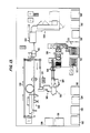
- Fig. 1 shows a block diagram flow chart of the operations to be performed in the manufacture of a cigarette.
- tobacco is received at the grade entry area 100.
- graded tobacco in bales is pulled according to a pull list which is displayed on a monitor according to a stored recipe.
- the tobacco has been previously marked with a bar code indicating the grade of the bale.
- tobacco is graded according to grade, belt, and crop year. The actual grading of the tobacco is not the subject of the present invention and will not be discussed in detail here.
- there are two types of tobacco processed These are Turkish tobacco and domestic tobacco. These two types may require different subsequent processing and therefore may be received at different grade entry areas 100.
- the bar code on the bale is read and automatically compared with a grade code stored in the recipe file indicating the grade of tobacco required. If the received bale is acceptable, it is sliced into smaller sections which are weighed so as to in feed the appropriate amount required by the recipe, preconditioned to provide an appropriate amount of moisture for subsequent delamination, and then passed to the strip condition area 102.
- the slices are delaminated in a delaminating feeder which passes the tobacco to a conditioning drum.
- the conditioning drum increases the temperature and the moisture level of the tobacco to be within a predetermined range.
- the tobacco flow is divided into two equal parallel lines. Each of these lines has a separator in which the lighter, loosened lamina is separated from the heavier, unloosened leaf by an ascending air stream. Moreover, dirt particles are separated from the light lamina. The heavier lamina is exposed to another conditioning process in a steam flotation chamber. This results in an additional loosening up of the tobacco.
- Grade entry area 100 together with strip condition area form the receiving and blending (R&B) zone.
- R&B receiving and blending
- the GBS zone comprises three infeed lines which feed 20 bins arranged in two groups of five bin pairs.
- the bins of the GBS zone provide intermediate storage for various tobacco blends, which are not yet final blends according to the stored recipe.
- the various R&B zones communicate by conveyors to the three infeed lines of the GBS zone in order to fill the GBS bins.
- the various bin pairs are assigned to different types of blends. For example, four of the bin pairs may contain a Burley tobacco blend, three of the bin pairs may contain a Flue Cured tobacco blend, one bin pair may contain a Maryland tobacco blend, one bin pair may contain a Turkish tobacco blend, etc.
- Each bin pair of the GBS zone is connected by conveyor to feed either one of two infeed lines to the final blended strips area 106 (FBS zone).
- the FBS zone comprises four bin pairs which are fed with tobacco from the bin pairs of the GBS zone according to a recipe. That is, the tobacco being stored in the intermediate storage of the FBS zone is moved upon demand to the FBS zone in controlled quantities so that a final blend is obtained in each of the FBS zone bin pairs.
- the final blended tobacco is passed from one of the bin pairs of the FBS zone according to the recipe to the casing area 108.
- the casing area comprises a casing drum into which steam, moisture and casing are provided.
- the tobacco is passed to the cutting area 110 where it is cut to the proper size for the tobacco product being produced, according to the recipe.
- the cut tobacco is then dried and cooled in the drying and cooling area 112 and then passed to the top dressing area 114.
- the casing area 108, cutting area 110, drying and cooling area 112 and top dressing area 114 form the cutting and casing zone (C&C) of the process. Further details of the C&C zone are set forth in co-pending application serial number 865,483, filed May 20, 1986 and assigned to the assignee of the present invention, the disclosure of which is incorporated herein by reference thereto.
- the portion of the system made up by the R&B, GBS, FBS and C&C constitutes the primary processing portion of the cigarette manufacturing process.
- the tobacco is transported to the cut filler storage area 116.
- This area comprises a plurality of bins for storing the cut filler until it is needed for the final cigarette making step.
- the cut filler is transported via conveyor to the rod making area 118 where the cigarette rods are formed.
- the rods are packed together usually 20 to a pack in the packing area 120.
- the packs of cigarettes are then packed into a carton in the carton packing area 122.
- the cartons of cigarettes are then packed into a case in the case packing area 124.
- the cases are then assembled together on pallets in the pelletizing area 126.
- One rod making machine, one packer, one carton packer, one case packer and one palletizer are assembled into a single making and packing (M&P) complex.
- a single plant may contain 72 or more such complexes.
- the M&P complexes are fed from bins which are themselves fed from the FBS bins.
- the M&P bins are connected such that three bins feed six complexes. This provides sufficient flexibility for the simultaneous manufacture of a plurality of cigarette brands even if one or more of the complexes become disabled.
- the palletized product is moved to the finished goods area 128 for storage or shipment for sale.
- a plant also may include an automatic guided vehicle (AGV) system comprising a plurality of guided vehicles which operate under computer control to bring materials to the M&P complexes when needed and to transport finished product to the finished goods area when the cases have been palletized.
- AGV automatic guided vehicle
- the plant also includes an automated materials storage and retrieval system known as a factory service system (FSS) which takes the form of a computerized warehouse for storing and retrieving the materials to be delivered to the M&P complexes by the AGV system.
- FSS factory service system
- the foregoing provides an overview of the cigarette making process controlled by the present invention. In general this comprises primary processing, making and packing and finished goods. It should be understood that the foregoing describes the activities of a single plant. However, a plurality of plants may be operating at the same time. It is also possible that some of the activities discussed above may be carried out at a first plant and some of the activities may be carried out at a second plant with the product of the first plant being shipped to the second plant for further processing. All of these possibilities are contemplated by the present invention.
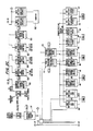
- Fig. 2 shows the general architecture of the computer system used in the present invention.
- the system includes a mainframe computer system 130 located at corporate headquarters.
- This computer system is referred to as the level IV system and is used to generate the material specifications, product specifications, and process specifications which are eventually used to produce product at the shop floor.
- the level IV system could be any mainframe but in this particular instance is shown to be an IBM computer system.
- material is used hereafter to refer to a material which is purchased for use in manufacturing a product.
- a “product” is something which is manufactured even if the “product” is only used for the manufacture of another product. Accordingly, as will be discussed in more detail below, both materials and products are used in the manufacture of other components.
- the level IV computer system 130 may be connected to a plurality of plants.
- a single plant is shown in Fig. 2 to comprise a level III computer system made up of Digital Equipment Corporation (DEC) VAX 11/750 computers 132 and 134 as well as DEC VAX 8600 computers 136, 138 and 140.
- the level IV system is shown to communicate to the level III system through one or more DECnet/SNA gateways at 56 KB. This communication link is served by one or more DEC PDP 11/24 computers.
- the computers of the level III system communicate to each other through an ETHERNET communication link.
- This is a conventional collision detection type communication link provided by DEC. It is not essential that the computers of the level III system be from the same manufacturer. However, it is imperative that they be capable of communication with each other. Accordingly, by having the computers originate from the same vendor, the communication between computers is easily achieved by using vendor supplied systems.
- the level III systems perform functions to be discussed below. These functions may be assigned to individual computers or several functions may be performed by a single computer. For example, as shown in Fig. 2, computer 132 performs all primary processing management functions, computer 134 performs maintenance functions, computer 138 performs plant management system functions, computer 136 performs back-up management systems functions and computer 140 acts as a plant management system back-up computer.
- the level II system comprises VAX 11/750 computers 142, 144, 146, 150, 152, 154, and 170-173. These computers are from a single vendor to facilitate communication between systems which is essential for a computer integrated system to operate properly. Computers 142 and 144 are assigned the task of data concentration. Each of these computers is connected to receive data signals from 36 M&P complexes. The data signals from the 36 M&P complexes are routed to a common disc storage area 166 by each computer 142, 144.
- VAX 11/750 computers are used for the Making and Packing Management System and the Factory Service Management, as shown in Fig. 2a, if one computer can handle all of the processing needs of both systems. Also, the use of VAX 11/750 computers is optional. Computers having greater computing power can be substituted for the VAX 11/750 computers. For example, VAX 8600 computers are now available and can be used in place of the VAX 11/750 computers.
- the disc storage area 166 may be accessed by the level III and level II computers as shown in Fig. 2 in order to pass data between these systems as necessary, as will become more apparent below.
- Computer 146 is the M&P management system and is programmed to pass data on to the M&P complexes on the shop floor, as will be discussed below.
- Computer 152 is the factory service management system (FSM). This computer receives requests from the M&P management system (MPMS) for specific materials such as case blanks, cigarette paper etc to be used in the M&P complexes and sends instructions to computer 162 which forms the factory service control system.
- the factory service control system (FSCS) controls the automated warehouse and automatically stores and retrieves materials in response to the instructions from the FSM system. Further, the FSM system sends requests to computer 150 which forms the automatic guided vehicle management system (AGVMS) for an automatic guided vehicle to deliver the retrieved goods to the requesting M&P complex.
- AGVMS automatic guided vehicle management system
- Computer 150 receives requests from the FSM system for guided vehicles to deliver materials to an M&P complex or receives requests directly from the M&P management system to carry palletized goods to the finished goods area.
- the AGV management system sends instructions to the AGV control system in computer 158.
- the AGV control system carries out the instructions by causing a series of guided vehicles to deliver materials to the various M&P complexes upon request, or transport products to the finished goods area upon request.
- the AGV management system keeps track of the progress of the guided vehicles and reports back to the M&P management system when a request to deliver goods to a specific M&P complex has been met, and also keeps track of finished goods being transported to the finished goods area and instructs the finished goods management system of the identity of the goods if such a request is made.
- the finished goods management system resides in computer 154 and sends instructions to the finished goods control system resident in computer 160.
- the finished goods control system operates a series of conveyors which transport the finished goods to a series of loading docks for loading onto vehicles for transportation to various locations and controls several elevators for moving the finished goods to storage locations, if necessary.
- the finished goods control system also checks the cases for proper seal and informs the finished goods management system of any defects.
- the finished goods management system determines the dock onto which the cases should be loaded and determines which cases are to be temporarily stored based on the state of the loading docks and the defects in the cases reported by the finished goods control system.
- Computers 156 and 164 act as control system back-up computers and can take over the responsibilities of the control system computers if the need should arise due to failure of one of the control system computers.
- the level I system comprises computers 156, 158, 160, 162 and 164, discussed above, and a single computer at each M&P complex, which may be a PDP 11/83 computer. Each of these M&P computers is referred to as a computer at the complex (CATC).
- CATC computer at the complex
- One such CATC 168, 169 is shown connected to each data concentrator system 142, 144. However, there are actually 36 such CATCs connected to each data concentrator, as discussed above.
- Each CATC communicates with a data concentrator through the ethernet communication link and to the MPMS through the data concentrator.
- the transmission of production data or the like is carried out by the data concentrator accessing the common storage data 166 to store or receive data. Communication of requests or the like is referred to as a transaction and is carried out by the data concentrator communicating directly with the MPMS through the MPMS.
- the CATC receives information in the form of production data and the like from the complex. This information is stored in the CATC and every 5 minutes the CATC sends data to the data concentrator for storage in the disc storage area 166.
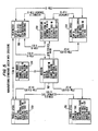
- the level II system includes primary processing host computers 170 and 172. Each host computer has a backup computer available to take over operation in the event of a failure. Host backup computer 171 backs up computer 170 and host backup computer 173 backs up host computer 172.
- Host computer 170 together with backup computer 171 control the receiving and blending portion of primary processing through a pair of redundant node computers 174, 175 and 176, 177, which are level I computers.
- Computers 174 and 176 are primary control computers and computers 175 and 177 back up the primary computers 174 and 176.
- Computers 174 and 175 control the grade entry functions through the infeed to the GBS bins.
- Computers 176 and 177 control the outfeed of the GBS bins.
- host computers 172 and 173 control the primary processing functions from the outfeed of the FBS bins to the infeed to the cut filler storage. Additionally, these computers control the flavoring kitchen in which the flavorings such as the top dressing and the casing are prepared. Host computers 172 and 173 operate through level I node computers 178-187 which are connected as primary control computers 178, 180, 182, 184, and 186, and backup computers 181, 183, 185, and 187. Computers 178 and 179 control the outfeed of the FBS bins, computers 180 and 181 control four cutting and casing lines, computers 184 and 185 control the infeed to the cut filler storage, and computers 186 and 187 control the flavoring kitchen.
- the level 0 system comprises a plurality of distributed remote modules (DRMs) which interconnect directly to motors, sensors, valves, etc on the processing equipment.
- DRMs distributed remote modules
- the DRMS may be individual computers connected with backup computers and should also be DEC equipment to facilitate communication.
- Communication between the primary processing management system computer 132 and the host computers is through an Ethernet collision system while communication between the host computers and the node computers is through a polling type communication link. Communication between the node computer and the DRMs is also carried out via a polling system.
- the sensor signal values read by the DRMs are stored in memory and periodically read by the controlling node computer. Similarly, these values are then periodically read by the controlling host computer. Conversely, data relating to materials specifications, product specifications, bill of materials lists and process specifications is periodically passed down from the management computer to the host computers, to the node computers and then to the DRMs.
- the level 0 system comprises computer control system provided by the equipment manufacturer. This equipment must be modified to be certain of compatibility with the DEC equipment used in the rest of the system. Such modification would be readily apparent to one of ordinary skill in the art.
- data relating to sensed variables is periodically polled by the CATC (corresponding to the node computer) and passed up to the host system. Also, data relating to specifications for products, processes, materials and bills of material is passed down to the level 0 computers on a periodic basis as needed.
- Fig. 3 gives a clearer picture of the relationship of the different computer levels and the functions performed at each level.
- the blocks in Fig. 3 indicate software systems.
- level IV is at corporate headquarters and is primarily concerned with corporate objectives.
- Levels 0-III are at the plant sites and are connected with carrying out the corporate objectives in the plants. The corporate headquarters is usually removed from the plant site and the information generated at level IV is passed to a plurality of plant sites. Thus, it can be seen that the levels 0-III would be duplicated for each plant site.
- level IV includes a scheduling system 200 which interfaces with a materials requirement planning system 202.
- the scheduling system 200 together with the material requirements planning system 202 are designed to manage the manufacturing capacities, machines, people and material to meet the marketing and inventory objectives as stated in the business and strategic plans of the company.
- the result of this effort at level IV is a master schedule, a portion of which is passed down to a plant scheduling system 203 at the plant level.
- the master schedule includes a long range portion which matches machine capacity to brand requirement. The long range portion covers a period of approximately 2 to 10 years.
- the master schedule also includes a mid-range portion which covers a period of from 1 to 2 years.
- the mid-range portion applies inventory objectives and calculates the machines and people required.
- the mid-range plan also sets plant goals.
- the master schedule includes a near term portion which covers 1 to 2 quarters. This portions sets near term objectives in terms of inventory level to utilize all employees and establishes machine line-up to accomplish these requirements.
- each plant Based on the master schedule, each plant produces a plant schedule covering 1 to 6 weeks. Each plant also creates a daily schedule by finished goods to support the near term master schedule, distribution, advertising promotions and international distribution requirements.
- the plant schedule system 203 provides plant execution schedules on a 1 to 6 week horizon. This system assigns machine capacity to achieve the plant demand objectives set by the master schedule.
- the manufacturing standards system (MSS) and the bill of materials system interact to produce a database containing all of the specifications and bill of material information needed to produce a finished product.
- the MSS system contains the capability to issue revisions to specifications and implement the revised specifications according to a predetermined date of implementation.
- the database generated in the MSS is passed to the factory manufacturing standards system (FMS) at level III in the plant.
- FMS factory manufacturing standards system
- the FMS duplicates the majority of the database in the level IV system and also generates an additional file which contains data organized in a manner which can readily interface with the plant scheduling system.
- This additional file known as the product definition file, contains records assessable according to schedulable products. Each record contains references or pointers to the specifications and bills of material information necessary to produce a version of one schedulable product.
- the plant scheduling system operates by accessing the records of the products to be manufactured and passing this information down to the management system(s) involved in making that item.
- the plant scheduling system and the factory manufacturing standards system are shown as being a part of an overall block labelled plant manager system. This is because the plant manager system performs functions in addition to the scheduling and FMS functions. These additional functions include those performed by a plant inventory control system and a plant production data base system. These systems gather data and analyze data according to plant and corporate needs. The gathered data may be used in the plant scheduling system and passed to the corporate level IV as the need arises.
- the primary processing manager 210 is also a part of the level III systems.
- the primary processing manager (PPM) receives a product definition file containing the pointers to the specification data from the FMS and converts it into recipes for the various machines under its control. To produce these recipes, the PPM accesses the data indicated by the pointers in the records of the product definition file and assembles this data into recipe file records.
- Different machines may be provided on the shop floor to perform the same function and, therefore, may require slightly different operating parameters to function properly.
- the data relating to machine settings is associated with a product or group of products, this information is contained in the file passed down from the FMS but the information is not readily usable to directly control the machines.
- the PPM converts this information into recipes for the various machines by accessing the data and accumulating it in the appropriate recipe record. Also, some operating instructions and machine specifications may be maintained only at the plant level and are not passed down from above since these operating instructions do not relate to any particular product or group of products. These instructions are merged into the recipe by the PPM so that the recipe contains all instructions necessary for operating each machine on the shop floor.
- the PPM contains all of the recipes which are scheduled to be run by the machines under its control for a period of about six weeks. These recipes are passed to the host computers 170 and 172 when they are needed.
- the host computers are at level II and store all of the recipes.
- the host computers pass down only the recipe for the current run and the recipe for the next subsequent run which are stored in current run and subsequent run registers at level I. As soon as the current run is completed, the recipe for the subsequent run is loaded into the current run registers at level I and the recipe for the next subsequent run is loaded into the subsequent run registers. This is true for both the R&B host 170 and the C&C host 172.
- the host computers may store algorithms which are used to convert the recipes into actual set points for the machines on the shop floor.
- the set points define actual opening degree of valves, speeds of motors, etc used by the control systems. This conversion is made and the set points are passed to the level I systems which are shown to be the receiving and blending control systems 220 connected to the host 170 and the final blending control systems 222, casing and cutting control systems 224 and the kitchen control system 226 connected to host 172.
- Level 0 Data in the form of control variables is sensed by the level 0 system and passed up the levels as discussed above. This data makes its way up to the level III system to be used in the plant scheduling function and is passed up to the level IV system on a selective basis.
- the making and packing management system 230 is also part of the level II systems. Management system 230 functions in a manner somewhat similar to the operation of the host computers in that it passes specification data to the 36 level I CATCs as needed to control the present run and the next subsequent run.
- the term "run” refers to the production of a scheduled product during a scheduled time period.
- the CATCs pass the run information on to the computer controls on the machines themselves (indicated generally by 240) which operate on the 0 level.
- the CATCs perform data gathering functions by receiving sensor signal data from the machines and then pass this information to the M&P management.
- the CATCs also receive signals from the machine operator when additional materials are required for the M&P complexes to operate. These requests are passed to the M&P management system which communicates the request to the factory service management system. Since the CATCs store all specification data relating to the current run, when a signal is received that, for example, new cigarette paper is required, the CATC knows the exact specifications of the paper and passes this information along to the M&P management system and then to the factory service management system.
- the AGV management system 150, factory service management system 152 and finished goods management system 154 will be discussed in greater detail below.
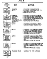
- MSS Manufacturing Standards System
- the MSS comprises a database containing files which store the various specifications needed for making product.
- the files are shown in Fig. 4 to comprise a product file 250, a process file 252, a material file 254, a change order file 256, a product structure file 258 (also known as a bill of materials file), an item master file 260, and a revision file 262. The content of each of these files is discussed below.
- the following data elements are the used in the composition of the main access keys into the files.
- the primary access keys used in the MSS system are defined below with their actual name and the component data elements that comprise the key.
- FIG. 4 shows the relationship between the keys and the files. The content of the files themselves will now be discussed.
- This file contains the detail specification records for finished and intermediate products.
- the specifications in this file include specifications for products such as cigarettes (CGT), manufactured filters (FLR), and cut filter tobacco (CFT).
- CCT cigarettes
- FLR manufactured filters
- CFT cut filter tobacco
- control record for each type of specification.
- the control record contains the maximum high and low values for specific variables (i.e., reasonableness limits).
- the Product file also contains the processes for making the product together with a code indicating the machine on which the processes can be run. From the product file, the process file can be accessed to obtain the specs for carrying out the process. For example under the item id for a particular cigarette, item ids for the processes of cigarette rod making (CRM) and tipping (TPR) would be included together with an indication of the machines on which these processes can be carried out. There may be multiple entries if there are several machines on which the processes can be carried out.
- CRM cigarette rod making
- TPR tipping
- Detail specification records contain the detail specifications for cigarettes, filters and cut filler tobacco.
- the records contain an indication of the SPEC-TYPE.
- the SPEC-TYPE for finished cigarettes is CGT
- the SPEC-TYPE for manufactured filters is FLR
- the SPEC-TYPE for cut filler tobacco is CFT.
- the purpose of the SPEC-TYPE is to group all spec records of the same type to facilitate access to all spec records of the same time.
- each record of the product file may contain a BRAND code, if applicable, a REV LEVEL code, CHANGE ORDER #, an EFFECTIVE-DATE-IN code indicating the effective date of the specification, and SPEC DATA indicating the actual specifications of the product.
- the SPEC DATA may contain the tar and nicotine levels of the cigarette, the moisture content of the cigarette, as well as the length, diameter and other descriptive specifications of the cigarette.
- CURRENT-ITEM - Identifies the one Current product specification for an ITEM-ID.
- CURRENT-BRAND - Identifies the one Current product specification for each relative SPEC-TYPE for a specific BRAND, if applicable.
- CURRENT-SPEC(a) - Identifies all Current product specifications by SPEC-TYPE.
- EFFECTIVE-DATE - Identifies the date a product specification can be implemented in production.
- Control records are also provided in the product file. These records contain the reasonableness limits for certain variables in the detail specification records. There will only be one Control record per SPEC-TYPE.
- the control records can contain, for example, the upper and lower reasonableness limits on tar and nicotine content of the cigarette and the upper and lower reasonableness limits on the diameter or length of the cigarette.
- the term "reasonableness limits" is used to indicate the upper and lower bounds which any entered spec may have. These limits may be used to test entered specs to be certain that they are not clearly in error.
- the control record can be accessed directly by using the following access key: CURRENT-ITEM - uniquely identifies the current product control record.
- the process file 252 contains two types of detail process specifications: item-specific and generic.
- Item-specific process specifications for each machine type or configuration of machines contain process parameters and instructions for machine setting, etc necessary to produce the desired product.
- the process parameters and instructions may vary depending on the product to be produced.
- the machine type or configuration of machines is indicated by a MACHINE data element.
- Generic process specifications for each machine type or configuration of machines contain process parameters and instructions that will always apply regardless of the product to be produced.
- TPR tipping
- CCM cigarette rod making
- FAM filter rod making
- CFL cut filler tobacco blending
- MACHINE data element may be validated against values for MACHINE and SPEC-TYPE in a Process Equipment Identification Table maintained for that purpose.
- the detail specification records contain the item-specific process specification data. For each ITEM-ID in the Product file there will be at least one process specification record containing the manufacturing instructions necessary to produce the product. There can be multiple detail process specification records for an ITEM-ID depending on whether there are any documented machine-related differences.
- each process file record contains an ITEM-ID code indicating a particular process, a BRAND code, if applicable, a REV LEVEL code indicating the revision level of that particular specification record, a CHANGE ORDER number code, an EFFECTIVE-DATE-IN code indicating the date the specification record is effective, and SPEC DATA indicating the specifications such as the set up instructions, etc for the recorded process. If applicable, the SPEC DATA will have a MACHINE code appended to it to indicate the machine for which the data is valid.
- PROCESS-KEY Uniquely identifies each specification revision of any process.
- CURRENT-SPEC(b) identifies all Current process specification records by SPEC-TYPE.
- CHANGE-ORDER-NO Identifies Process specifications associated with a Change Order.
- EFFECTIVE-DATE Identifies the date a process specification can be implemented in production.
- ITEM-REV-Key Identifies all Process specifications associated with a specific revision to an ITEM-ID.
- the generic specification records contain the process specification data that is applicable to a specific machine or configuration of machines regardless of the product being produced on the machine(s).
- Generic process specification records do not have any references to a specific ITEM-ID.
- a special value ('GENERIC-' & SPEC-TYPE) is stored in the ITEM-ID.
- the generic specification records can be accessed directly by using the following access keys: PROCESS-KEY - Uniquely identifies a Generic Process Specification Record. CURRENT-SPEC(b) - Identifies the Current Generic Process Specification Record.
- control records contain the reasonableness limits for certain variables in the generic and item specific process specification records. There will be only one Control Record per process SPEC-TYPE.
- the access key to Control Records has a special value ('CONTROL-' & SPEC-TYPE) in ITEM-ID.
- the access key is: CURRENT-SPEC(b) - Identifies the Current Control Record for a SPEC-TYPE.
- the material file contains two types of detail specification data for purchased materials: item-specific and generic.
- Item-specific material specifications contain physical and chemical parameters and supplier instructions that vary depending on the item purchased.
- Generic material specifications contain process parameters and supplier instructions that will apply to all variations of the same grade regardless of the item purchased.
- Material specification data is provided for items such as filter tow (FT), closures (CL), cigarette paper (CP), carton blanks (CR), case blanks (CS), crushproof boxes (CX), foil (FO), purchased filters (FR), inner frame stock (IF), labels (LA), poly wraps (OW), plug wrap (PW), tipping paper (TP), and tear tape (TT).
- FT filter tow
- CL closures
- CP cigarette paper
- CR carton blanks
- CS case blanks
- crushproof boxes CX
- foil FO
- purchased filters FR
- IF inner frame stock
- LA labels
- PA poly wraps
- PW plug wrap
- TT tear tape
- the specification data is similar to that provided in the Product file. That is, descriptive specifications are given for such characteristics as density, color, size, etc. Also, a grade designation is provided, if applicable.
- the detail specification records contain the item-specific specification data for purchased materials. For each ITEM-ID, there is one Current material specification record. The following information in the detail specification records can be accessed directly using the following access keys: ITEM-REV-KEY - Uniquely identifies each spec revision of any material.
- CURRENT-ITEM - Identifies the one Current material specification for an ITEM-ID.
- CURRENT-SPEC(a) - Identifies all Current specifications by SPEC-TYPE.
- CHANGE-ORDER-NO Identifies Material specification revisions associated with a Change Order.
- EFFECTIVE-DATE Identifies the date a material specification may be used to purchase materials.
- the generic specification records contain the generic material specification data for general types of purchased materials. The types included are: CP - Cigarette paper specifications are related by their grade. TP - Tipping paper specifications are related by their grade. OW - Poly wrap specifications are related by their grade.
- Generic material specifications have a corresponding entry in the Item Master file. They are linked to the material specifications by the SPEC-TYPE and GRADE. Generic material specifications use the value of the grade in the ITEM-ID.
- the generic material specifications can be accessed directly using the following access keys: ITEM-REV-KEY - uniquely identifies each spec rev of any material. CURRENT-ITEM - identifies the Current specification for any generic material.
- control records contain the reasonableness limits for certain variables in the item-specific and generic material specification records. There is only one Control Record per SPEC-TYPE.
- the access key to Control Records has a special value ('CONTROL-' & SPEC-TYPE) in ITEM-ID.
- the access key is: CURRENT-ITEM - identifies the Current control record.
- the change order file contains information about each Change Order Number.
- a Change Order Number is issued by the system and assigned by the user to a specification or bill change or related group of changes. It is used as a 'connector' into the Revision file to identify all revisions associated with the Change Order.
- a Change Order Number must be assigned to each change prior to the creation of a new or revised spec or bill.
- the system will prohibit updating or creation of specifications or product structures without a valid Change Order Number.
- the actual implementation of all changes is initiated and controlled through the Change Order as opposed to individual specification revisions.
- a Change Order record contains summary information about the entire change (i.e. effective date, change reason code, approvers, reason description).
- Each specification record contains its own detail change documentation for that part of the overall change.
- the information in the Change Order file can be accessed directly using the following access keys: CHANGE-ORDER-NO - Uniquely identifies a Change Order record. STATUS - Identifies the status of Change Order records and is used to group changes by status for display (e.g.. Unapproved, approved, implemented). EFFECTIVE-DATE - Used to produce chronological lists of pending Change Order records.
- the Product Structure File is a modified version of the product structure file of a commercially available software package sold by Comserv Corporation of Cincinnati, Ohio under the name AMAPS (Advanced Manufacturing and Production System).
- the Product Structure File contains all of the prior, current and future components of a product by ITEM-ID number and serves two purposes: to provide the relationship of an assembled product to its components (intermediate products and/or purchased materials) and to provide replacement instructions for any component of the assembly. MSS uses this file to operate component lists for selected products. In order to determine which revisions of a component to use, a date selection criteria is applied to each record.
- the entries of the product structure file are in terms of product/component.
- the item id for each component is given but the current rev level for each component is not set forth in the product structure file.
- This information can be obtained from the item master file or the product, process, or material file containing the specs for the component.
- the proper product/component relationship to use is determined based on the date selection criteria applied.
- An example of a product structure record is set forth below.
- the first revision AA of the product definition for the cigarette CGT1 established that the tipping paper TP1, cigarette paper CP1 and the filter FLT1 are components. This revision was made effective on 1/1/86. However, this revision was superseded by revision AB which replaced tipping paper TP1 with tipping paper TP2. Accordingly, the REV LEVEL-IN for CGT/TP1 is AA since revision AA called for TP1 as a component and the REV LEVEL-OUT for CGT/TP1 is AB since this revision replaced TP1 with TP2 as of 2/2/86. In a similar manner, revision AC replaced FLR1 with FLR2 so that the REV LEVEL-IN for FLR1 is AA and the REV LEVEL-OUT for FLR1 is AB.
- the date criteria is used by accessing the product structure records according to a particular date and using only the components which are in effect as of that date. Actually, only the rev level need be stored in the product structure records, with the effective dates being stored in the rev file.
- the system is designed to determine the components of the product structure file which are effective on the requested data by reconciling the rev levels with the effective dates stored in the rev file.
- the component item ids are used to access the item master file to determine the rev level effective on the date requested and the material or product files are accessed to determine the specs for the components as well as the processes needed to produce the component products.
- the information in a product structure record can be accessed by using the following access key: STRUCTURE-KEY - Uniquely identifies a Product Structure record.
- the Item Master file is a modified version of an item master file found in the AMAPS software package mentioned above.
- the Item Master file contains one record for each assembled product or purchased material referenced in the Product Structure.
- the record contains information about that item not found in the Product, Process or Material files.
- the record contains item-specific purchasing data, planning data, and accounting data.
- Each item has a unique identifier - its ITEM-ID.
- the next available ITEM-ID code is automatically assigned to the new item according to rules established for each spec type.
- the system includes a function which performs a reference check to ensure that the Assembly ITEM-ID and all Component ITEM-IDs exist before being included in a Product Structure file record.
- the data in the Item Master file can be accessed directly using the following keys such as the following: ITEM-ID - Used to obtain any item Master record. BRAND - accesses information by brand code.
- Item Master file An example of the type of information which may be stored in the Item Master file is as follows: Descriptive Information Accounting Information (Inventory Category, Total Budget cost, Cost Control Code, etc.) Material Control Information (Item Type, Planner/Buyer Code, Make/Buy Code, Order Policy Code, Safety Stock, etc.) Lead Time Information (Planner Time, Buyer Time, Queue Time, Vendor Time, etc.) Spec type Brand code
- the Revision file is also a modified version of a file contained in the AMAPS software package.
- This file is used to track the revisions to any information about each item in the Item Master file. Changes that cause a new revision record to be created for an item include component additions or replacements in its Product Structure or updates to its specification(s). A revision control record must exist prior to accepting any changes to a specification or product structure file.
- the Revision file stores codes indicating the revision levels to a spec or bill as well as the effective dates of the spec or bill, and points to the spec or bill data associated with each revision. In this way, the Revision file archives and keeps a record of all changes so that old specs and bills can be accessed and compared to new specs and bills.
- the following information is stored in this file: Item-id Revision level Effective-date-in Approval status Change order number
- the information in the Revision file can be accessed directly using the following access keys: ITEM-REV-KEY - Uniquely identifies a Revision record CHANGE-ORDER-NO - Identifies all revision records associated with a specific Change Order.
- FIG. 6 gives an example of the manner in which the information for a particular product can be accessed through the files.
- Figure 6 shows the total product definition for a manufactured cigarette.
- the record 300 for the particular cigarette in the Item master file can be accessed with the cigarette brand or any of the other access keys given above together with the date of interest to obtain the item id of the cigarette, if this is unknown, and the rev level of the cigarette.
- the cigarette record 302 in the product structure file can be accessed as shown in the drawing and the components of the cigarette can be determined.
- the circular blocks in Fig. 6 indicate the information required to access records in the files and the square blocks indicate the data in the records.
- the product structure record 303 for the cigarette of interest lists all of the components of that cigarette together with the item id for each component.
- the item master record for each component can be accessed to determine if the component in question is a material or a product and to obtain the effective rev level as of the date. Then the appropriate material or product record can be accessed. For example, one component of the cigarette is cut filler tobacco (CFT).
- CFT item master record may then be accessed using the CFT item id code. From the item master record, it can be determined that the CFT is a product and the CFT product spec 306 can be accessed as well as the CFL process spec record 308. From the product spec record 306, the control record 310 using the product type code with the item id and rev, and from the process spec record 308, the generic CFT spec record can be accessed using the process type and item id with rev.
- the filter (FLR) item master record can be accessed to determine that the filter is a product.
- the FLR product spec record 320 can be accessed to determine the specifications of the product and the processes used to make the product.
- the control record spec 322 for the product can be determined.
- the FLR product structure record 324 can also be accessed using the filter item id and the date to determine the components of the filter.
- the FLR process spec record 326 can be accessed to determine how to carry out the processes combine the components of the filter and the generic spec can be determined from this record.
- the filter tow (FT) item master record and the plug wrap (PW) item master record can be accessed from the FLR product structure file and then the material spec records 336 and 338 for these materials can be obtained.
- the same procedure can be used to obtain the item master 340 and product spec record 344 for the plasticizer (PLA).
- the same procedure can be used to obtain the item master 348, 350, 352 and 354 and material spec records 356, 358, 360 and 362 for the cigarette ink (INK), purchased filter (FR), tipping paper (TP) and cigarette paper (CP), as well as the generic specs for TP and CP.
- INK cigarette ink
- FR purchased filter
- TP tipping paper
- CP cigarette paper
- the cigarette product file record is accessed to obtain the product specifications and the control record 370 information.
- the process spec records for the manufacturing process can be found in the process spec file. This information shows up as tipping process specs (TPR) and cigarette rod process specs (CRM).
- TPR tipping process specs
- CRM cigarette rod process specs
- the generic process specs for the TPR 376 and for the CRM 378 can be found in these records.
- Fig. 7 shows the relationship between the revision file, the change order file and the other files.
- the revision file lists all revisions for any item id.
- the files in Fig. 7 include a portion of the files for the filter as shown in Fig. 5.
- the revision file 262 is shown and the change order file 256 is shown.
- the revision file a record is maintained for each previous and proposed revision to the specs or bills for each item id.
- the item master file record for the filter may include revision AC as the current revision implemented for the filter.
- the revision file would show revision AC is the latest implemented revision under the item id code and would also include entries for the previous revisions AA and AB as well as any other revisions which may be pending but not yet approved, approved but not yet implemented or the like. These same revisions are contained in the appropriate specification records.
- a change order is an authorization to create a new product, process, material or bill, or revise an existing spec or bill. For example, if the filter in Fig. 7 was to be changed from a length of 10mm to a length of 15 mm, a change order must be issued first. The change order number would be required to initiate new specs. These new specs would include changes to all specifications affected by the change in length of the filter. This may include revisions in the product specs and the process specs for making the filter. All these changes would be grouped under the same change order number, for example, change order number 1. In addition, there would be created an entry in the revision file under the item id code corresponding to each item being changed and new rev designation would be assigned to each change. The changes would also be entered in the appropriate product spec file, process spec file and product structure file by producing a new record under the item id number with the new rev designation.
- the effective date of the change order is the date on which the change order should be implemented in the plants. As soon as the change order is approved, the change order and the corresponding new specs and bills are passed down from level IV to the lower lever systems so that the plant level is notified of the implementation date of the change order. In this manner, the scheduling systems in the plants can take the change order into account.
- the actual time of the change order implementation that is, the shift at which the change order should be implemented, may be left to the plant management system to correspond to the best use of available inventory, machines, etc. All previous revisions of these specs will be used in FMS until such time as the plant level management systems determine when the revisions associated with the change order should be effected.
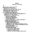
- Fig. 8 shows the steps to be followed to create the implement a change order.
- approval must be obtained to create a change order and a valid change order number must be obtained from the system.
- the steps are shown as being undertaken by the R&D department. Of course, other departments may also be authorized to obtain valid change order numbers. Once a valid change order number is obtained, the user is authorized to input spec or bill data into the system.
- step 402 data is permitted to be input into the appropriate files.
- the system automatically checks for authorization to use the spec create function, validates the change order as pending approval, and validates the change order as having the proper spec type.
- MSS In the event that a new item is being added to the system, MSS automatically creates a new item master file record to obtain a new item id number. The new item id number is then automatically entered into the revision file and the first revision designation AA is assigned to the specs or bills being entered for that item.
- the system If the specs for an already existing item are being revised, the system generates the next rev level entry in the revision file. If the last revision designation for the item id involved was AC, the new designation would be AD, for example. Data is then entered into the files involved. For example, a new entry may be made in the product specification file under the item id for cigarettes and the new revision level to indicate a new length for the cigarette. All corresponding entries in other files affected must be made at this time. These entries would all come under the same change order number but may have different rev designations depending on the last rev designation assigned to the particular item id number. All entries made at this time are accompanied by an unapproved status code indicating that final approval of the new specs has not yet been obtained.
- the system validates codes, dates (expiration date, etc), machine types, brands, etc.
- the system also may perform a reasonableness test on the spec values being entered to be sure that they are not outside of some unacceptable range. Further, particularly if the specs being entered include changes or additions to specs in the bill of materials file, the system may perform a check to see that all fields affected by the entered change receive corresponding changes. Such validations and tests may be performed as deemed necessary to ensure the integrity of the database after the data entry is completed.
- step 404 a manual review of each data entry is undertaken by subject matter experts and, if the inspected data entries appear to be correct, the unapproved status of each entry is removed individually. However, the unapproved status of the entire change order remains in effect.
- step 406 the division of the corporation which initiated the change order reviews the specs and bills associated with the change order to ensure that all necessary data entries have been made and that all data entries are correct. The initiating division then approves the change order and may modify the original effective date associated with the change order to implement the change order. If the effective date is modified, the change order and the specifications in the various files are updated en-masse with the new date.
- step 408 and in step 410 other divisions or groups in the organization affected by the change order review the new specs and approve or disapprove of the change order as a whole. Once all involved groups have approved of the change order, the status of the change order is changed to approved. At this point, the change order is automatically transmitted to the plant level in step 412.
- the FMS stores a duplicate of the database in the MSS except for the unapproved change orders and spec types not applicable to the plant.
- the FMS automatically creates two new files to organize the spec references in a form which can more readily be married to the scheduling information to be received from the scheduling system.
- the Product Definition file contains a record for each product which is the subject of the scheduling system. That is, for each schedulable product a record is created.
- Schedulable products are products which are stored for use in a subsequent process step. For example, referring to Fig. 1, the output of the receiving and blending section as stored in the group blended strips area 104 is a schedulable product, as is the output of the product stored in the final blended strips area 106. Also, the output of the cutting and casing line as stored in the cut filler storage area is a schedulable product. In the making and packing area, the output on the palletizer to the finished goods area 128 is a schedulable product.
- Fig. 9 shows one record 418 of the Product Definition file. Each record of the Product Definition file is accessed by reference to the item id of the schedulable product and a version number of the product.
- the record 418 relates to finished cases of cigarettes and sets forth a full list of all material item ids, process item ids and product item ids needed to produce a finished case structure. Codes are included to distinguish products from materials and processes from products and materials so that the system can discern which components are associated with process specs, which components are associated with product specs and which components are associated with material specs. In Fig. 9, this coding is indicated by boxes surrounding the products and labelling on the processes. That is, from Fig. 9, it can be readily determined that the finished case structure 420, the finished carton 422, the finished pack 424, the manufactured cigarette 426, the cut filler 428 and the filter 430 are products to be manufactured.
- this information is used to point directly to the appropriate spec files which enable the system to quickly determine all specs of the manufactured product to be used to make that version.
- the process and material item ids are set forth below each product item id so that the product definition points directly to the materials and processes needed to produce a product.
- the process spec 423 key is included for the finished carton so that the process specs can be obtained directly.
- codes are included to indicate any other schedulable products in the Product Definition record. In record 418 this is indicated by giving a version number on the cut filler. Accordingly, the system knows that the cut filler is a schedulable product and can directly access the Product Definition record for the cut filler.
- the Product Definition records are assembled by the system using the connectivity relationships as explained with reference to Fig. 6.
- the system could be run without the Product Definition file by directly determining the relationships of the records as discussed with reference to Fig. 6 each time that this information was needed.
- the formation of the Product Definition file enables the system to operate more efficiently and provides a readily available mechanism for displaying the product definition on a display screen to a user monitoring the status of changes specs within the plant.
- the version number of the item id in the Product Definition file relates to the change orders discussed above. Each time a change order is passed down from level IV, a new version of each Product Definition record affected by the change order is produced. In order to keep track of the versions and the dates of implementation of each version, a Configuration Matrix is assembled by the system and stored in the FMS.
- Fig. 10 shows the structure of the Configuration Matrix.
- the column indicates the item id code of the schedulable assembly and the upper row indicates the date and shift of implementation.
- the entries in the matrix indicate the version of the item id to be run on a particular date and a particular shift. Therefore, when a particular item id is scheduled by the plant scheduling system to be run, the Configuration Matrix is accessed to determine the product definition version of the item id which should be used. That version of the product definition is then entered into the schedule and passed to the Primary Processing Management system and/or the Making and Packing Management system.
- the date that a change order is to be implemented is passed to the plant level but the actual time of the implementation may be left to the plant level management system.
- the formation of the Configuration Matrix is a function of the change control administrator which has access to the schedule and to the inventory of the plant.
- the change control administrator has the flexibility of implementing the change order at the most convenient time for the plant and may make this decision based on factors such as inventory on hand. For example, if a new version of a finished case calls for a cigarette manufactured with a cigarette paper with different graphics, and there is large quantity of the prior cigarette paper on hand, the new version of the item id may not be implemented until late in the day that the change order became effective.
- change order would include an actual shift for implementation and the Configuration Matrix would be simply a function of the change order with no input from the change control administrator.
- the implementation date of the change order can be accompanied by a code indicating implement immediately, implement as soon as possible, or implement when feasible to direct the actual implementation time. If the change order is accompanied by an implement immediately code, the change order would be implemented on the next shift after it becomes effective regardless of the unused supply on hand.
- the change order administrator may be a manual function or software may be derived applying set rules to be followed in the event of the receipt of the codes associated with the implementation date of a change order.
- the Configuration Matrix and the Product Definition file provide sufficient information or provide pointers to information in other files maintained in the FMS so that the specs for products to be produced can be accessed by the various management systems in a form which can readily be converted into instructions for the shop level machines. Further, the Product Definition file provides a convenient way in which the information from the scheduling system can access or marry the information from the spec system.
- the production planning functions on level IV are divided into two general areas, scheduling 200 and material requirements planning 202.
- the scheduling system determines the quantities of product to be made to meet corporate needs and the materials requirement planning system 202 ensures that there are sufficient people, machines and materials available to meet the production schedule.
- Fig. 11 shows an overview of the production planning function which forms the scheduling system 200.
- the Production Planning function starts with long range planning done by Resource Capacity Planning 500 which establishes the capacity requirements of the corporation by quarter.
- Operations Planning 502 is used to refine the quarterly capacity requirements by applying additional constraints in the form of inventory policies. New monthly goals and budgets can be created from the Op Plan whenever desired.
- a more refined capacity plan and special scheduling techniques necessary to meet the inventory policies is passed to the Master Production Scheduling function 504 which is responsible for maintaining inventory levels and supporting the Marketing effort on a near term planning horizon.
- the Master Schedule will apply the people on-roll and modify an existing machine line-up to utilize the people available.
- the projected inventory levels will reflect the results of utilizing current capacity. All planning up to this point is done by brand/style. That is, the plans are made out in terms of brands required (e.g. Camel, Winston, Winston Light, etc) and style (e.g. cartons, cases, etc).
- Plant Scheduling 506 and Machine Scheduling 508 are performed at level III and take the Master Schedule's weekly brand/style requirements and create a detail daily (Plant schedule) or hourly (Machine Schedule) schedule by specific finished good id for each M&P complex. These two functions define the detail necessary to operate the processing control systems used to operate the plants.
- the resource planning 500, operation planning 502, and master scheduling 504 are performed on level IV while the plant scheduling and machine scheduling are carried out at level III.
- Material is planned on a weekly basis with daily "call outs" to have material delivered to a plant on the day that the material is required to maintain a predetermined number of days safety lead time.
- the production is reported at the end of each shift to provide the necessary information to compare the actual production made and the resources used to the plan production and the resources which were planned.
- Fig. 12 shows the relationship of the scheduling system with the computer levels and the management systems of the plant.
- the operational plan 502 can be a spread sheet type program which can be manipulated to determined the cost, time etc ramifications of different long range plans and different master schedules. In this sense, the operational plan acts as a simulator of the scheduling function.
- the operational plan results are passed to the master scheduling function 504 which actually creates the master schedule for the company.
- the master schedule is passed back to the operational plan block which can then model the master plan and determine probable outcomes of alterations to the master plan. All of the information from the operational plan function 502 is passed to the long range plan function 500 to assist in the long range planning of the company.
- the master scheduling function receives an indication of the domestic demand from the domestic forecast function 501 which uses well known techniques to predict domestic demand.
- the master scheduling function 502 receives demand data from the inventory policies function 503 which determines the desired inventory levels above the domestic forecast in order to compensate for, for example, plant closings for vacation and the like and in order to provide a buffer if demand is above that predicted.
- the master scheduling function receives input from the international forecast function which determines the probable international demand for product. This results in a total forecast which must be scheduled by the master scheduling function.
- the master schedule is passed down to the production requirements functional block 507 on level III.
- the production requirements block 507 also receives orders form the export order processing system. This determines the total demand to be produced by the plant.
- the system of Fig. 12 operates on an inventory demand or make to stock system for domestic product and operates on an order demand or make to order system for export product. Accordingly, while the domestic product is inventoried and the domestic forecast can be altered to account for greater demand periods or lower demand period than expected, the export orders are shipped as they are produced and must be given higher priority. Thus, the production requirements block 507 gives priority to the export production requirements and passes on the production requirements for both international and domestic to the plant scheduling block 506.
- the plant scheduling block allocates the number of making and packing complexes to international requirements necessary to meet the international orders and allocates the rest of the production capacity to the production domestic product.
- the actual plant schedule is passed back to the master schedule block 504 as shown by line 515.
- the master scheduling block 504 uses this information to adjust the master schedule. For example, if the demand for export was low, more domestic product would have been made by the plant then was called for by the master schedule and the master schedule is then adjusted to take this fact into account.
- the machine scheduling block 508 receives the plant schedule and makes out a detailed run by run making and packing schedule to accomplish the plant schedule. From making and packing, the plant operations are back and the cutting and casing lines are scheduled to ensure that the proper product reaches the making and packing complexes at the proper time to meet the plant schedule. The final blended strips lines are then back scheduled from the cutting and casing lines and the receiving and blending lines are back scheduled from the final blended strips lines.
- the detailed schedules are down loaded to the PPM and the MPMS and are used to access the product definition files in the plant management system which down loads the specs necessary to carry out the schedules.
- the machine schedules are produced about three weeks in advance and are used to provide call outs in the call out function block 520. These call outs are supplied to vendors to order the materials needed to meet the schedule. The materials are then delivered by the vendor just in time to meet the schedule.
- the call outs are also provided to the material requirements planning block which also receives the master schedule.
- the MRP reconciles this information to provide a long term (on the order of 26 weeks) forecast to the vendors for materials demand in the plants.
- the actual production figures from the management computers are sent to the machine scheduling block so that the detailed machine schedules can be adjusted to compensate for short term anomalies in the actual plant production. For example, if one making and packing complex is down for repairs, the production expected from that complex will have to be rescheduled. Any adjustments in the machine schedule are reported back to the plant schedule and to the master schedule so that the plant and master schedules can be appropriately adjusted.
- Long range capacity planning is well known in general and is used to match the machine capacity to a Strategic Plan on a one to ten year planning horizon.
- the main focus of this function is to allocate the machine capacity of a given configuration (85mm length, 120mm length, slim, etc.) to the Brand/Styles which make up the various production configurations. Brand/Style allocation to different plants is done to utilize the existing capacity of the plants. Any machine conversion to increase or decrease existing or future capacity is planned by this function. Simulations and 'What if ...' questions are answered using the information available to this function.
- RCP Resource Capacity Planning
- the Primary capacity and tobacco requirements can be derived from the same machine line-up. Wrapping Material volume can also be calculated by extending the Bills-of-Material with the production volume generated by the machine line-up.
- the brand/style placement, machines available, efficiency and the machine utilization created by this function is used to establish the capacity information used by the Operations Planning function.
- Operations Planning is an extension of the Resource Capacity Planning function.
- Operations Planning expands the planning of capacity to the weekly horizon and applies additional planning constraints in the form of Inventory Policies.
- the capacity allocated by RCP may be good for the quarter planned; however, there may be capacity problems on a week to week basis which did not appear.
- the Op Plan is essentially a simulator of the plants and provides the ability to analyze the capacity problems on a weekly basis.
- the Op Plan is used to trial fit various scheduling solutions to meet the Inventory Policy objectives.
- the Op Plan can also be used for simulations and 'What if ... ' questions.
- the manpower requirements by labor grade can be generated by applying the Labor Standards to the line-up. This will calculate the labor requirements to support what is actually needed to meet the inventory objectives based on machine capacity.
- the machine line-up can be modified up or down to utilize the people on-roll. This modified machine line-up is based on an average men-per machine.
- the manpower requirements by labor grade can be matched to the Human Resources available for people planning.
- Manufacturing Goals and Budgets can be created to support the Op Plan upon request. Monthly Manufacturing Goals and Budgets are kept for two years - current and next years. New Manufacturing Goals and Budgets can be established throughout the year (Latest Estimate).
- the weekly capacity information and the scheduling techniques used to satisfy the inventory objectives are used by the Master Production Schedule to schedule the near - mid term planning horizon.
- the Master Production Schedule projects the inventory on hand amount by brand/style for the next 78 weeks.
- the MPS balances the demand to the capacity (machine and/or people) available to establish the production rate by brand/style which the factories must meet in order for the MPS to be met.
- the MPS breaks the planning horizon into smaller planning periods called "smooth periods". Each "smooth period" has an inventory objective or target to meet as established by the domestic forecast, the international forecast and the inventory policies for the period.
- the MPS will calculate a smooth machine line-up to accomplish the inventory objective by brand /style based only on machine capacity.
- the scheduler has the option of applying the people on-roll to the machine line-up in order to modify the smooth line-up to reflect people available. This will cause the smooth line-up to be increase or decreased to utilize the people.
- the machine line-up required to meet the MPS indicates how much production each plant must produce by brand/style. Inventory objectives are reconciled by the scheduler using the MPS information.
- the MPS generates the weekly machine line-up by brand/style which the plant follows. The first three weeks are in the control of the Plant Schedule. Weeks four through six are reconciled between the Plant Schedulers and the Master Scheduler. The MPS will create a new smooth line-up for weeks 7 through the end of the first "smooth" planning period.
- the MPS calculates and maintains inventory by brand/style. Each brand/style has a standard finished goods id which is produced unless overridden by the Plant Scheduler. This standard finished goods id is used for all material planning functions generated from the MPS.
- a new production plan is created each time the Master Production Schedule (MPS) is executed.
- the new production plan is based on the current inventory balances, the Plant Schedule for the first six weeks and the inventory policy (target levels) which the Master Scheduler is aiming to achieve.
- a new machine line-up is generated for weeks seven to the end of the planning period to utilize the people on-roll to accomplish the inventory policy.
- the machine line-up for the first six weeks may need modification to bring the Plant Schedule in line with the Master Schedule requirements or because the plant capacity may have changed.
- a Line-Up report is used by the Master Scheduler and the Plant Schedulers to reconcile the line-up.
- the machine line-up in the Master Schedule is modified to reflect the latest plant capacity as defined by the Plant Schedulers.
- a new Plant Schedule for weeks four, five and six is created from the new machine line-up established in the Master Schedule.
- the Plant Schedulers have complete control of the Plant Schedule for weeks one, two and three. These weeks are NOT modified by the Master Schedule.
- the weekly machine line-up generated by the Master Schedule specifies the number of machines to run in each plant-department by brand/style. The assignment of brand/style production to the desired plant-department was made by the capacity priority established for each brand/style by the Master Scheduler.
- the weekly machine line-up assumes that same number of machines will be ran each day at the same efficiency rate.
- a machine line-up which is less than a whole machine represents a split daily production: ie a weekly machine line-up of 2.2 means a daily machine line-up of 2 machines for four days and 3 machines for one day.
- the Plant Schedule takes the weekly MPS requirements and creates a daily machine line-up for the standard finished good id as defined by the MPS.
- the Plant Schedule allows for special finished good items to be scheduled. When a special finished good item is scheduled the Plant Schedule subtracts the amount from the standard finished good item.
- An example of this is the scheduling of export items. If 100 million cigarettes is scheduled for the standard domestic finished good item and 10 million cigarettes were scheduled for an export order the standard domestic finished good item would be reduced to 90 million cigarettes. The original target of 100 million cigarettes for the brand/style is maintained; however, the specific finished goods which make up the brand/style will change according to the demand for specific items.
- the Plant Schedule provides the daily machine line-up and production volume which runs the plant. All supporting plant functions, such as material requirements, primary production, machine overhaul schedules, are scheduled from the Plant Schedule.
- the Plant Schedule provides a daily run sheet which lists the items to be produced (by finished good id), the number of machines required to produce the volume required, the efficiency rate used to calculate the machine line-up and the labor staffing required to operate the machine line-up by labor grade.
- a "pick" list showing each wrapping material component required to produce each finished good item is also provided.
- the Master Scheduling functions support the corporate inventory policies established to reach a corporate Business Plan.
- the first six weeks of the Master Schedule are refined and reconciled using current plant capacity information (people and machines) as defined in the Plant Schedule.
- the Plant Schedule for weeks four, five and six is regenerated to reflect this reconciliation.
- the Plant Schedule for weeks one, two and three are under control of the Plant Scheduler and can only be changed in the Plant Schedule which is than reflected in the first three weeks of the Master Schedule.
- This interaction between the Master Schedule and the Plant Schedule establishes a detail Making & Packing schedule.
- the Primary facilities are backed scheduled from the Making & Packing schedule. These functions are performed on the level IV system.
- Each plant maintains their Plant Schedule on the plant level III computer.
- the Plant Schedule information is transferred between the corporate level IV computer and the plant level III computer. Bill-of-material and manufacturing specifications will vary between plants.
- the Plant Schedule maintained in each plant provides the ability for each plant to schedule where and when a Product will be produced.
- the Factory Manufacturing System maintained in each plant defines how a product is made and the material necessary to produce the product on the date which it is scheduled to be produced.
- the Machine Schedule generated from the Plant Schedule produces a detail sequence of runs by work center (complex or primary line) for each item-id and the date/shift it is to produced.
- the detail Machine Schedule is married to the product definition via the configuration matrix to determine the version of the product to produce based on the item-id and the date/shift it is scheduled to be produced.
- the marriage of the Machine Schedule and product definition determines where, when and how a product will be made.
- the level II computer is a staging area for the detail runs waiting for processing. A one day to one week holding tank is maintained at this level. Minor alterations to the scheduled runs can be made at this level by authorized schedulers.
- the actual processing of the runs is done by the level one computers.
- the level one computers provide information on the current run and the next run to be produced.
- the product to be made, the facilities to be scheduled and the Manufacturing Standards to use are loaded into the processing computers and displayed to the machine operators.
- Authorized machine operators can alter the schedule and/or components materials and process set points in order to maintain production requirements.
- the Plant Schedule defines which complex(s) (Maker-Packer) produces which brand/styles. Daily capacity available is maintained for each complex-brand/style.
- the Plant Scheduler assigns a Priority to each complex which can produce a given brand/style.
- the machine line-up established by the Master Schedule is allocated to specific complex assigned by the Plant Scheduler. The following example shows how this is accomplished:
- Machine line-up established by the Master Schedule is 11 machines for the week or 2.2 machines a day. Export requirements will need 3 machines during the week.
- the standard domestic finished goods item id to schedule is 5124010 and the generic export finished goods item is in 7924000 (this reserves capacity to produce specific export orders at a latter date).
- the first complex to be scheduled is complex 5. There are five machines available during the week for this complex so all are used. Export requirements take three of the five days and are scheduled for Monday, Tuesday and Wednesday. The second priority is complex 6. This complex is being overhauled until Friday. The complex is scheduled on Friday when it becomes available. Only six machines have been scheduled on the first two priorities. The remaining five machines to schedule are done on complex 1 because the complex is available all week. Complex 2 is not needed by this brand/style and is available for another brand/style if required.
- a detail Plant Schedule by day for the specific finished goods id 5124010 and the generic export finished goods id 7924000 has been created.
- the machine capacity reserved for export items is identified by the finished goods id 7924000. This reserved capacity will be consumed by actual export orders. Any capacity left over will be converted to the standard domestic finished goods item 5124010. Additional export capacity will be taken from the same standard domestic finished goods item.
- the complex to schedule can produce two million cigarettes based on the machine speed and the current efficiency rate.
- the first three export orders will be scheduled on Monday to meet the due dates.
- the remaining capacity of fifty-thousand cigarettes (2 million - 1.950 million) will be scheduled as the standard domestic finished goods item.
- the last export order will be scheduled on Wednesday with the remaining capacity that day being converted to the standard domestic item.
- the export capacity reserved for Tuesday was not used; therefore, the capacity is scheduled for the standard domestic item. Note that this will cause the Plant Schedule to over schedule the domestic item and under schedule the export capacity requested by the International forecast.
- the total amount of the brand/style which was scheduled by the Master Schedule was maintained; however, the mix was not.
- the next Master Schedule run will take this over production into account when a new production schedule is generated.
- a detail Plant Schedule has been created from the Master Schedule and outstanding export orders (the same logic of scheduling export orders is applied with specific domestic orders requested by Distribution such as test markets and cold storage items).
- the Plant Scheduler has the ability to manually override or add to the generated schedule. This is done by using the add request or the change schedule request. These functions are covered in the Plant Scheduling User Manual.
- the final step in scheduling the Production facilities in the Machine Scheduling function takes the daily machine line-up from the Plant Schedule and provides a hourly run schedule to operate a specific complex (maker-packer combination) and make a specific finished good item.
- the Primary facilities are scheduled using the hourly run schedules. This information is passed to the processing systems which operate the facilities.
- a detail run schedule is created for each work center based on the Plant Schedule established in the above manner.
- the first Machine Schedule which is created is for the Making & Packing operations.
- the daily Plant Schedule is divided into the various runs required to produce the finished goods scheduled.
- the start time and end time for each run is calculated using the machine speed and the current efficiency rate.
- the Cut Filler Storage (CFS) bulkers and the Feeder to support the complex are scheduled using the default assignment established by the Plant Scheduler.
- the Plant Scheduler can modify the CFS bulker and/or feeder assignment upon request.
- the following information is provided in the Machine Schedule for Making & Packing:
- WC is the Work Center (sub-unit and complex);
- RUN is the run sequence number;
- FG ID is the finished goods item to be produced;
- ORDER # is the specific order number;
- S is the shift: DATE is the day the run is to start on: START is the planned start time; DATE is the day the run is to end; END is the planned end time;
- FD is the feeder to use;
- CASES is the amount of cases to produce.
- the Machine Schedule is matched with the configuration matrix to ascertain the version to be used for the finished goods item.
- the version to be used is the one in effect for the date of the run. Run 010 above for finished goods 5124010 needs to have the version in effect during the 7 shift on December 15th.
- the correct version is added to the detail runs created by the Machine Schedule.
- the Primary facilities are now ready to be back scheduled. There are three areas in Primary to be scheduled. They are the Casing & Cutting lines, the Final Blended Strip lines and the Receiving & Blending lines.
- the Casing & Cutting lines support the Cut Filler Storage bulker replenishment schedule.
- the first phase of the Casing & Cutting schedule is to determine the CFS bulker replenishment schedule.
- the Making & Packing run schedule specifies the CFS bulkers assigned to support each complex. The status of which CFS bulkers are currently in use, which blends are in the CFS bulkers and the amount of tobacco in each bulker is provided when a new schedule is to be calculated. The CFS bulker depletion projection is calculated using this information.
- the CFS bulker replenishment schedule is derived by knowing when a bulker will be depleted and when it is required to be used again. A replenishment window exists when the Casing & Cutting line can be used to produce the run to replenish the bulker. Based on the replenishment window and the amount of time required to produce the amount of the blend needed, the four Casing & Cutting lines are scheduled to meet the CFS replenishment schedule.
- the projected CFS bulker depletion is shown as
- the blend code is shown within the brackets.
- the replenishment window is the time between when the bulker is depleted and the next time it is scheduled for use.
- the first replenishment window for CFS 10 is between the 7th shift on Tuesday and the 7th shift on Wednesday.
- the blend, H133 can be produced anytime within this window to support the Making & Packing schedule which generated the need.
- the corresponding Casing & Cutting schedule is developed by meeting the replenishment windows.
- the Casing & Cutting runs are bracketed by the CFS replenishment run number.
- WC is the Work Center (Casing & Cutting line); RUN is the run sequence number; BLEND is the item to be produced; S is the shift; DATE is the day the run is to start on: START is the planned start time; DATE is the day the run is to end; END is the planned end time; DT is the CFS bulker to receive the production: SO is the FBS bulker which will supply the tobacco for this run: and POUNDS is the amount of cut filler to produce.
- the version of the blend to produce is derived from the Factory Manufacturing Standards in the same manner as the Making & Packing version number.
- the product definition for the blend is looked up in the configuration matrix and the version in effect for the date and shift is ascertained.
- the FBS lines are scheduled in the same fashion as the Casing & Cutting lines were.
- the FBS bulker depletion schedule is calculated using the FBS bulker status and the Casing & Cutting schedule generated above. Requests for additional FBS (Part 2) tobacco to support other facilities or international tobacco orders will be added to the Casing & Cutting schedule.
- the FBS replenishment schedule is then calculated to fit in the replenishment window.
- the two FBS lines are then scheduled to support the FBS bulker replenishment schedule.
- the same illustration shown for the Casing & Cutting schedule is appropriate for the FBS area.
- the FBS line schedule is used to calculate the GBS bulker depletion schedule. Using the same logic as defined for the Casing & Cutting and FBS areas applies for the GBS area. When the depletion schedule is known the replenishment window and schedule can be calculated. The three Receiving & Blending lines are than scheduled to support the GBS replenishment schedule.
- Material Requirements Planning is divided into two planning horizons. Long range material planning is done for a 26 week period. The material required to support the Master Schedule is calculated by taking the current balance on-hand and projecting when the material will be consumed. Material requirements are calculated for each of the 26 weeks in the planning horizon. The material requirements are based on the standard finished good item which is scheduled by the Master Schedule.
- the "call outs” are created to support the detail Plant Schedule.
- the “call outs” are calculated by subtracting the daily material requirements from the inventory on-handial is ordered to maintain a predetermined number of days safety lead time.
- the specific wrapping material is ordered to support the specific finished good ids which are scheduled by Plant Scheduling.
- Primary Processing is broken into three major areas which consist of Receiving and Blending/Group Blended Strips including areas 100, 102 and 104 of Fig. 1, the Final Blended Strip area 106, and the Casing and Cutting/Cut Filler Storage comprising areas 108, 110, 112, 114 and 116. These areas are controlled by the Level III Primary Processing Manager 210 (Fig. 3), two redundant Level II host computer systems 170, 171(Fig. 2B) and 172, 173 (Fig. 2C) and a plurality of Level I node computers and Level 0 Distributed remote processors as also shown in Fig. 2B/C.
- the basic configuration of the Level II, Level I and Level 0 computers is based on a hardware system sold under the name Anatec and a software system sold under the name CRISP provided by Anaconda Advanced Technology, Inc.
- CRISP 32 is used on the Level II system
- CRISP 16 is used on the Level I system.
- CRISP is a conventional layered software package which permits application programs to written for the ANATEC system.
- the Anatec system uses DEC computers.
- the CRISP package includes databases which will be referred to below as CRISP databases. These databases are stored in the memories of the computers on the individual levels of the system. Communication is provided between the levels using CRISP routines, as will be referred to below.
- a DECnet router 133 In addition to the CRISP routines, a DECnet router 133 (Figs.
- the Network/Receiver is an applications program which uses the DECnet router to communicate between different levels of the system.
- the Primary Processing Management functions are divided between the level III system 210 of Fig. 3 and the level II host systems 170 and 171. That is, there is no clear distinction between functions performed on the Level II system which should be considered management functions and which should not. Therefore, the term Primary Processing Management System (PPMS) will be used hereafter to refer to the functions performed both by the system 210 and the hosts systems 170 and 172. A distinction will be made, however, by referring to either the PPMS level II system or the PPMS, level III system where appropriate to indicate the functions performed on each level.
- PPMS Primary Processing Management System
- DPCS Distributed Processor Control System
- the DPCS is a software function which resides on Level 1.
- the PPMS is an area management system which assists many departments in the plant as well as outside the plant in providing two types of control: material and production.
- the PPMS is accountable for maintaining real-time inventories in an Inventory function.
- the system provides the following:
- the Inventory function provides several sub-functions.
- a Material-On-Hand sub-function provides plant management with status of displays of in-process and floor inventories of all materials used or produced in the Primary process. These displays are updated every sixty seconds to give real-time data to the viewer.
- PPMS also contains an In-Plant Inventory Update sub-function which is responsible for keeping the in-plant inventory records up-to-date based on:
- PRS Primary Receiving System
- the PRS keeps track of inventories of tobacco and other materials being brought into the plant and inventories of product being shipped. This information is input to the system and used as discussed below.
- PPMS's Batch/Run History sub-function is actually a combination of an Inventory function and a Production Reporting function. This function is responsible for:
- the Transaction Logger collects all of the inventory transactions that occur in a given period (receipts, shipments, adjustments, usage, and production) and provides the data daily to the Level IV systems for a variety of uses.
- the PPMS Production Reporting function uses data supplied by a Material-On-Hand function and the Transaction Logger to provide shift and daily reports on items such as material usage and inventory status.
- a Receiving and Blending (R&B) Grade Entry Interface at the Grade Entry area 100 provides R&B personnel with the proper bale material identification as bales are prepared to be consumed in the R&B operation. This data is based on scanning of bar codes on the tobacco bales as the bales are prepared to be processed. The bar code data is input to the system relative to each bale received and supplies in real-time the data necessary to determine if the bale should be used at a particular point in time.
- the PPMS ensures the ability of the Level I systems to meet the required standards for making product in Primary.
- the PPMS includes a Recipe and Operating Instruction function which, along with the Manufacturing Standards System and the Factory Manufacturing Standards System, marries corporate controlled specifications with plant controlled specifications to supply the Level I computers with the necessary recipe components and operating instructions for the production runs.
- the Recipe and Operating Instruction function produces a Recipe File and an Operating Instruction File using information from the MSS database and information relating to plant owned data. The records in these files are then passed down to the lower levels for use in controlling the processes of Primary Processing.
- the PPMS also includes a Scheduling function which aids in keeping an orderly and coordinated sequence to the production runs.
- PPMS supplies the tools to adjust the schedule to accommodate problems which develop in the system.
- the Level III software provides all of the direct user interface with the PPMS. Additional user interface in Primary Processing (but not with the PPMS) may be had at the Distributed Processor Control System (DPCS) which resides on Level I and actually controls the operation of the distributed remote processors (DRMs of Fig. 2b). All PPMS displays, edits, and requests for hard copy reports are made through Level III software.
- DPCS Distributed Processor Control System
- Level III software provides interface between the PPMS and:
- the PPMS organizes and provides the plant personnel with the necessary display and edit capabilities of the recipe and operating instructions required to make the various blending runs in Primary Processing.
- the recipe and operating instructions must be available at Level I before a production run can be made.
- Recipe data is generally characterized as data contained in a particular blend's Bill of Material. Operating instructions are the various set points, limits and ranges for items like temperatures and moisture levels that are used to control and monitor the making of blends.
- Recipes and operating instructions are the standards by which the various processes are controlled.
- the data is provided by the Level IV system through the MSS and this data is considered to be corporate data and is stored in the common disc storage area 166 (Fig. 2a) as part of the FMS database.
- the corporate data associated with any particular blend can be accessed by reference to the appropriate record of the Product Definition File which points to the pertinent records and files of the FMS database.
- the data is controlled at the plant level and is considered to be plant-owned.
- the PPMS forms two files.
- One file referred to hereafter as the Operating Instruction File, contains a record for each blend/version indicating the operating instructions for that blend/version.
- the operating instructions comprise actual operating parameters such as set points, pressures, flow rates, etc.
- the other file referred to hereafter as the Recipe File, contains a record for each blend/version indicating the recipe for that blend/version.
- the Recipe File contains quantities of the components to be used in a particular blend/version such as the amounts of the different types of tobacco to be used to make a blend/version.
- the data is maintained at PPMS Level III in the common disc storage area 166.
- the plant owned data in these files actually augments the corporate data by adding to information which is specific to the equipment in that plant and is necessary to produce product on machines of that plant. Examples of plant owned data may include set point ranges of particular equipment, ranges of valves settings to provide a certain flow rate, etc.
- the entries in the Operating Instruction File and the Recipe File which contain corporate data cannot be changed by the plant personnel.
- the PPMS provides display-only capability for the user of this information. This means that if the data needs to be altered, it must be done through a change order in the MSS at Level IV and then resupplied to the PPMS.
- the interface of the PPMS to the MSS is described below.
- the entries of the Operating Instruction File and the Recipe File which comprise plant data can be altered by the plant personnel. Plant owned data can be edited through the PPMS. Editing of plant-owned data will also be described in more detail below.
- the second case involves providing a set of plant-owned data for a new version of a blend that already existed on Level III as a previous version.
- Level III PPMS Upon receiving notification of a new version of a blend, Level III PPMS surveys the Recipe and Operating Instruction Files to determine if this blend already exists in some form as a previous version. If a previous version is found, PPMS will use its plant owned data as the default set for the new version of the blend. Management procedures must be in place to assure that the data that is being used in the revised blend specifications are the required values.
- the computers of the Level I system store in memory buffers as a part of their CRISP database only the blend/version records for the current run and the next subsequent run. If the blend/version requiring a change in the plant-owned data is already in the current run buffer or the next run buffer in the Level I system, the data will not change unless the buf the buffers are cleared and the blend/version is re-requested.
- the corporate and plant-owned data for each section of the plant can be displayed for review and editing purposes. Of course, only the plant-owned data can be edited, as discussed above.
- the data for the Receiving and Blending area is displayed in two screens.
- One screen is used to display the recipe or bill of material type information.
- the second screen is used to edit and display the various operating instructions required to control the process.
- Two screens are used to display and edit the information relating to the Final Blended Strip area.
- One screen is used to display the recipe or bill of material type information.
- the second screen is used to edit and display the various operating instructions required for the Final Blended Strip part of the operation.
- Three screens are used to display the information relating to Casing and Cutting and Cut Filler areas.
- One screen is used to display the recipe or bill of material type information. This screen also allows for the edit and display of the high/low, minimum/maximum values for each of the material data items supplied by corporate. These ranges are plant-owned and are stored in the same record as the data item to which they relate.
- the second screen is used to edit and display parameters in the process which have set points, high/low limits and minimum/maximums associated with them. These parameters may also be plant owned and are stored in the Operating Instruction File.
- the third screen allows the edit and display of the operating points for moisture meters used in some processes and data for the top dressing tank number used in the casing process and the display of the top dressing menthol indicator used to indicate the production of menthol product.
- the number of screens used and the information displayed on each screen depends on the total amount of information to be displayed and the need to review the information. Also, the format of the displayed information is discretionary, although a standard column display has proven very effective. In every case, the information to be displayed on accessed based on the blend/version code of the product to which it relates.
- PPMS Level III provides plant personnel with the capability to display, edit, and print the schedules for each line in the Primary Processing area. Schedules are generated at Level IV and passed down to Level III. As part of the Level III Plant Scheduling and Machine Scheduling functions, any necessary modifications are made to the schedules and the schedules are finalized or committed. The main purpose of the editing of the schedule at Level III is to make last minute changes to the schedule or to add runs that were rejected by the down loading procedure. Before a schedule is passed down to Level II or to Level I, the schedule must be committed through a Level III Commit function. This is a manual function which authorizes the schedule to be used. This is done each time that a schedule is changed at a higher level, even if no changes are made at the PPMS Level III.
- the schedule will be used as provided by the higher level systems.
- manual intervention through the PPMS commit function is possible.
- the manual intervention is in the form of alterations in the schedule made by displaying the current schedule, altering the schedule as needed and then storing the altered schedule. This type of manual intervention provides flexibility to the system to accommodate unpredictable events which cause unexpected alterations in the schedule.
- An accurate indication of inventory on hand is necessary to ensure that the schedule can be carried out in a timely manner and to ensure that orders for replacement materials can be made in a timely manner.
- the inventory data collection function of the present invention is divided into two sections.
- the first section pertains to the Material On-Hand function.
- the second section is the inventory adjustments programs.
- the PPMS provides numerous displays to allow the user to view various inventory items in the Primary Processing areas.
- the inventory items include floor items which consist of types and amounts of unprocessed tobacco on hand as well as partially processed tobacco received into the plant from another location but not yet used in any processes within the plant, and material held in bulkers such as the amounts types of flavorings on hand and the amounts and types of partially processed tobacco on hand in bulkers.
- Inventory data at Level III is stored in one major Inventory File which is stored in the common disc storage area 166. This file is a collection of data from the Level II R&B host computers 170,171 (Fig. 2B) and the Level II Casing and Cutting host computers 172,173 (Fig. 2C). The data is gathered approximately every 60 seconds from the Level II computers and provides an accurate snapshot of the amount of each item contained in the Primary inventory.
- Individual displays can be provided for each type of item in the inventory. For example individual displays can be provided for processed tobacco inventory, various types of floor inventories and the status of various bins. This provides an immediate visual indication of the on-hand amount of the various materials in the plant.
- PPMS provides programs to permit the updating of the plant's inventory maintained at the plant and the updating of the plant's inventory maintained at Level IV. These programs allow for modifying inventories of various types of materials. For example, different types of tobacco may be handled by different programs. On program may be provided for modifying Redried Leaf tobacco inventory. A second program may be provided for modifying Oriental Leaf tobacco inventory. A third program may be provided to permit the changing of miscellaneous floor inventory other than Redried Leaf or Oriental Leaf. Three adjustment displays are used to update the in-plant inventory maintained by PPMS and the Level IV plant inventory for the three types of inventories being kept. The operation of each display is functionally the same. The user requests one of the screens. The user then enters the pertinent data that will identify the material to be adjusted.
- the program based on the key data, will search the proper inventory file for data relating to the material. The information is then displayed to the user. After the user makes the appropriate changes, the new information is used to update the PPMS in-plant inventory. The changes made are also logged to update the Level IV plant inventory at the end of the day.
- Level III of PPMS interfaces with the Factory Manufacturing Standards system, with the Level II of PPMS and Level I. These interfaces are for the purpose of passing information upward from lower level systems to higher level systems and for passing information downward from higher systems to lower level systems.
- the interface with the Factory Manufacturing Standards is to collect specification data supplied by corporate systems for the various new and revised blends. PPMS marries this data with information supplied by plant personnel for items considered to be plant owned specifications.
- the interface with Level II of PPMS is to supply the combined data mentioned above to the various areas of Primary Processing. This is done to insure that each area has its data when the schedule requires the particular blend to be run. A similar interface occurs with Level I to assure that a copy is available at the lowest level for backup purposes.
- PPMS maintains a list of the various blend/revision combinations of specifications that it has supplied from Level III to Levels II and I.
- PPMS access the Factory Manufacturing Standards database to get the proper corporate data to prepare for down loading to the lower levels.
- the data that is collected from the Factory Manufacturing Standards is merged with data input at the plant level that is also part of the specifications for making a particular blend/revision combination.
- a message is sent to Levels II and I that the data is available to be copied to the respective levels. The manner in which the data is copied to the lower levels is discussed in greater detail below.
- the data that is copied is a combination of the new data and the old data. This data replaces whatever was previously stored at Levels II and I. After the corporate data has been combined with the plant data, the file containing the Receiving and Blending data is transmitted to the Level II PPMS and to the level I DPCS.
- Level II system is notified via the Network Sender/Receiver that the data is ready to be moved to Level II.
- PPMS at Level II then copies all of the specification data for the area from Level III to disk storage associated with the host computers at Level II. This action is performed by a direct disk to disk transfer to the disks of the active and idle Level II systems. At this point, the data replaces the previous specification information for the area.
- Level I In passing the data to Level I, the data is pushed from Level III directly to Level I.
- Level I computers also have disk storage available to them. A copy of the all the specifications pertinent to the Level I computers is maintained in the disk storage of these computers as backup data.
- each Level I computer has a current run memory buffer and a next run memory buffer which are part of their CRISP database and are loaded from the Level II system with the specification data for the current and next runs, respectively. This is the information which is actually used to carry out the processes in Primary.
- the information to be stored on the disks of the Level I system is sent via a direct disk to disk transfer.
- the data replaces old specification data on both the active and idle computers of the redundant computer systems at Level I.
- the data stored on the disk storage for the Level I computers acts as backup for the data loaded into the current and next run memory buffers by the Level II system in the event that there is a failure in the system.
- Level III of PPMS also interfaces with the Plant Schedule System 203 (Fig. 3) which generates the Plant Schedule and the Machine Schedule.
- the interface between the PPMS and the Plant Schedule System occurs after the Plant Schedule System receives a new schedule from Level IV.
- the new schedule is married with the specs in the FMS and the schedule information is passed on to the PPMS.
- the new schedule is then validated by the PPMS Level III.
- the user signifies to the system that the schedule for a line needs to be committed to Level II.
- PPMS Level III then signifies through the Network Sender/Receiver that there is a new schedule for a line. Level II then brings the new schedule down and replaces the old schedule.
- the new schedule is then ready for use by the Level II system to supply next run and shift schedules to the CRISP database on Level I. These schedules are also maintained on Level I as a backup measure in the event that there is a failure in the loading procedure wherein the Level II system Loads only the current run specifications and the next run specifications in the memory buffers of the Level I computers.
- Level III of PPMS There are three interfaces between Level III of PPMS and the other systems in relation to inventory reporting. These interfaces involve the accumulation of information from lower levels and reporting the information to higher levels for use in the Level IV Material Requirements Planning system 202 and Scheduling System 204.
- the first interface is for Material On Hand displays. This interface involves getting data from Level II and making it available via CRT to the user. Additionally, the data collected is made available to the scheduling systems at Levels III and IV and to Production Reporting functions.
- the second interface involves making adjustments to in-plant inventories in Primary. This interface is between the Level III and Level II systems. Displays are provided by Level III to the user. The changes made are indicated to Level II for updating the inventories maintained by the plant as well as notifying the Transaction Log function of the changes.
- the third interface, the Transaction Log involves collecting data regarding inventory transactions and making the data available to Level IV. Also, the Level III production reporting uses the data collected for shift and daily reports.
- the Material On Hand function comprises collecting data on the R&B Level II computers and the Cutting and Casing Level II computers and copying the data up to Level III at regular intervals.
- the data includes information on tobacco inventories in bulkers, tanks and bales. No notification is required from Level II that the Material On Hand data is available.
- Level III acts independently from Level II in bringing the data to Level III. The data that is brought up to Level III replaces the old data each time. The data is then available for viewing by the users. If there is a problem with acquiring new data, PPMS notifies the user that the data being viewed is not up-to-date.
- the inventory adjustment interface accesses three different inventory data storages maintained at Level II. These three storages relate to the three types of items being used - Redried Leaf, Oriental Leaf, and Miscellaneous Materials.
- the program remotely accesses the Level II active system to find the information requested. After the data is displayed or modified, Level III Inventory Adjustment notifies Level II of the changes to be made. Changes are made on an individual bale or item id. Data is not accumulated for many changes and then sent all at once for updating the plant inventory files. Upon receiving the notification from Level III, Level II makes the appropriate changes to inventory. These changes are also reflected in the Transaction Log for notification to Level IV.
- the Transaction Log is a chronological inventory event recorder that is used in the reporting function to produce shift and daily reports at Level III. It is the source for all data regarding Primary inventory movements for use by Level IV systems.
- Level III collects the data on a regular basis from the Primary Receiving System, Level II Receiving and Blending, the Level II Cutting and Casing. Each of these systems updates a Transaction Log file with data from material receipts, shipments, adjustments, and production histories. From the Transaction Log files created at the lower systems, Level III PPMS creates a single data storage. At the end of the production day, Level III schedules a batch job to send all of the day's transactions to Level IV. The data is also stored at Level III for a length of time before being deleted.
- Batch/Run history data is collected at Level III of PPMS.
- the Run/Batch history is data accumulated for each processing run of Group Blended Strips, Final Blended Strips and Cut Filler. These reports contain indications of the amount of the product produced, the amount of each component consumed to produce the product, and the characteristics of the product including moisture levels, etc.
- Level II After PPMS Level II has collected the required data for a production run, Level II notifies Level III of the availability of the Batch/Run History. Upon receiving the message of what file is to be brought from Level II to Level III, Level III will copy the file up. The data in the individual file is merged into an area Batch/Run History file.
- the data coming from Level II is in a file for run 1, on line 2 in the Final Blended Strips area on the 8 shift of 1/28/87. No other runs' data is in this file.
- the data is moved into the area file known as FBSBATCH.DAT.
- the data is maintained in this file for a predetermined time, such as three months.
- PPMS provides displays and hard copies of the Batch/Run History reports for the various areas of Primary Processing.
- Inventory position reports are also provided.
- the inventory position reports are a set of shift and daily reports that indicate the various transactions that can occur to products produced in the Primary Processing area.
- the products covered in the reports are Group Blended Strip, Final Blended Strip, Cut Filler, and Casing.
- the transactions involved are beginning inventories in cans and bulkers and total weight, receipt of material, production, usage, material shipped, adjustments to inventory, and final inventory.
- the beginning and final inventories are based on snapshots of the material on hand data at the beginning of each shift.
- the remaining transactions are based on entries made into the Transaction Log from receiving, shipping, inventory adjustment and batch/run history routines.
- a variance is calculated by taking the beginning inventory, adding receipts and production, subtracting shipments and usage, and either adding or subtracting adjustments. The value gathered by this calculation is then compared to the final inventory. The difference between the calculated value and the snapshot value is then displayed as the variance for each material id.
- a set of reports similar to the Inventory Position reports is provided for materials that are considered to be raw materials for a particular blending process.
- Raw materials are purchased materials for use in a process rather than materials produced by the plant, which are referred to as products.
- the raw materials In the Receiving and Blending and Group Blended Strips areas, the raw materials would be redried and oriental tobaccos, for example. In Cutting and Casing, the raw materials would include, for example, flavorings.
- the transactions involved are beginning inventory, receipt of material, usage, material shipped, adjustments to inventory, and final inventory.
- the reports are provided on a shift and a daily basis. The beginning and final reports are based on snapshots of the material on hand data at the beginning of each shift.
- the remaining transactions are based on entries made into the Transaction Log from receiving, shipping, inventory adjustment and batch/run history routines.
- a variance is calculated by taking the beginning inventory, adding receipts, subtracting shipments and usage, and either adding or subtracting adjustments. The value gathered by this calculation is then compared to the final inventory. The difference between the calculated value and the snapshot value is then displayed as the variance for each material id.
- PPMS Level II has several functions which it is responsible for in the areas of Receiving and Blending and Group Blended Strip. The functions involve interfacing with the distributed processor control system (DPCS) on the node computers on Level I, with the Level II computers, with the PRS which carries out the receiving functions and with other functions within PPMS.
- DPCS distributed processor control system
- All of the PPMS software in this area runs on the dual 11/750 VAX computer configuration for the Receiving and Blending area comprising computers 170 and 171 shown in Fig. 2B.
- PPMS software runs at all times on both computers. The only difference in the activities from the computer to the other is that software running on the "active" machine will actually write data, when required, to the DPCS and Level III computers. The PPMS software running on the "idle” computer will receive the same inputs from these external systems but will not write to them unless the computer becomes the "active" machine.
- Level II and Level I are based on a commercially available hardware system sold under the name Anatec and layered software system sold under the name CRISP by Anaconda Advanced Technology, Inc.
- the software used on these levels based on the CRISP software CRISP databases are stored in the memories of the Level II and Level I computers.
- the software run on the Level II computers uses CRISP 32 and the software on Level I uses CRISP 16.
- Level I When PPMS is providing data to Level I, it can occur in two ways. Each Level I computer maintains its own files in a CRISP database and also has disk storage specific to that computer. The first method involves PPMS writing data directly into the memories of the Level I computers using CRISP routines. In this case, PPMS is only able to place data on the "active" Level I computer. It is the responsibility of the level I software to assure that the data is transferred to the "idle" Level I computer.
- the second method involves the use of the DECnet system 133 shown in Fig. 2a.
- DECnet is a Digital Equipment Corp. communication product which is used to allow PPMS to perform a disk to disk transfer to place data directly onto the disks of both Level I computers (active and idle) for a particular work center or group of work centers.
- the new data is written over any old data on the disk thereby eliminating the old data and updating the information available to the Level I systems.
- the data on the disk storage acts as a backup for the data stored in memory. That is, during normal processing procedures, CRISP database memory buffers in the Level I computers are updated only with the current run data and the next run data for the sections for which the computers are responsible. This information is used to run the processes. However, if some failure should occur with the updating, the information to carry out the runs is available in the disk memory for each computer and can be used to avoid the need to shut down the production line.
- the first part involves the updating of Redried Leaf, Oriental Leaf, and Group Blended Strip floor inventories by way of receipts, shipments, inventory adjustments, and production runs. These updates are all handled via external system interfaces.
- the second part involves the periodic collection of the floor inventories of Redried Leaf and the Oriental Leaf for use by Level III.
- This part is not considered to be part of an external system interface because it reads data from inventory files maintained by PPMS on the R & B Host computer.
- Data is collected approximately every sixty second from the Redried Leaf inventory files and from the Oriental Leaf inventory file.
- the data is reconstructed into another file (RBMATONHAND.DAT).
- the RBMATONHAND.DAT file is copied to the Level III system every sixty seconds.
- Data for the R & B batch/run history is collected from three sources.
- the first source is a data file provided by the Level I computers at the end of a run.
- the software collects the data on the Level I computers and brings the file up to the R & B Host computer at Level II.
- the Level I software notifies PPMS software that a batch/run history is available for use by PPMS.
- the PPMS Batch/run software notifies the Scheduling software that a particular run had ended.
- the Batch/run software notifies the PPMS Inventory Update software about the batch/run.
- the software then waits for the Scheduling and Inventory Update functions to indicate that they are done with the Batch/run history.
- Level III system is notified that a batch/run is available for transmission from Level II.
- PPMS is responsible for providing the R & B Level I systems with the required recipe and operating instructions for making Group Blended Strip runs.
- PPMS provides recipe and operating instructions to the DPCS in two ways. The first way is based on a next run data request from the control system. The second method is based on notification from Level III that there is a new set of recipe and operating instruction data for the work center.
- the PPMS will check its Recipe File and Operating Instructions File to make sure that the recipe called for by the schedule exists on the Level II computer.
- the key to the files is a combination of blend code and spec version.
- PPMS will write through CRISP calls the recipe/operating instructions into the next run area of the memory buffer. PPMS will then set a flag associated with this memory buffer to indicate to the control system that PPMS has completed its down load of data to satisfy the next run request.
- Level II PPMS receives notification from Level III that there is now recipe and/or operating instruction data for the work area (i.e. R&B/GBS).
- Level II will bring a copy of the recipe and operating instructions maintained at Level III down to Level II.
- Level II PPMS then will copy the newest data down to Level I as a set with the unchanged data for other sets of recipes and operating instructions.
- DECnet file transfers are used to move the data in a disk to disk transfer. The new files are written directly over the old files so that the information on the Level I disks is updated.
- the Level II software will receive notification from Level III of availability of a revised set of recipes and operating instructions in the form of new or revised records for the Recipe and/or the Operating Instruction File.
- the notification will be in the form of a message through the Network Sender/Receiver software.
- Level II Upon receiving the message, Level II will issue a copy command to copy the files down to Level II.
- the files have already been created on Level III from data in the FMS database and from the plant owned operating instruction database. The data is then ready to be supplied to Level I.
- the Level II PPMS Scheduling function provides run data to the Level I system in the form of next run data and shift schedules.
- the next run data is used to prepare the particular line for the next run.
- the shift schedule is a list of the next eight to ten runs that are scheduled for a particular line.
- the Level II PPMS software monitors certain flags in the Level I computer memory which will indicate when a particular line has moved data in its next run buffer to its current run buffer, therefore leaving space for PPMS to provide the next run's data.
- Level II PPMS Upon receiving the notification, Level II PPMS checks to make sure that the runs it expects to be in the particular memory buffers match what are in the buffers. If there are any discrepancies between expected and actual run numbers, blend code or blend revision, PPMS will not down load any data to Level I until the schedule has been corrected or Level I is corrected. This situation is what is referred to as a "line lock" condition. It does not mean that the line is physically stopped from running. It only means that PPMS has recognized a discrepancy and does not want to down load data that is possibly erroneous until the scheduler has corrected the situation. The scheduler in this case may be in the form of manual intervention.
- PPMS will proceed to down load to Level I the next run data. This process includes validating that the required recipe and operating instructions are available and calling a recipe function routine to place the blend/version of the recipe specified in the schedule into the next run buffer.
- Level II PPMS will utilize the scheduled weight of the run and the recipe for the run to create a list of the required poundage for each item on the recipe. These poundages are then checked against inventory to make sure that enough material is available for use in the run. If enough material is found, PPMS will commit the inventory required so that it is considered unusable for future runs. If there is not enough available, PPMS will print out a message to warn production personnel of the lack of material. In each case, however, the required data for next run and recipe will still be down loaded to Level I.
- Level I When the next run data for the schedule and the recipe/operating instructions have been down loaded to Level I, PPMS then notifies Level I that the next run data is in the database and available for use. PPMS will then proceed with updating the shift schedule information at Level I for the work center with the next eight to ten runs. As discussed above, Level I maintains a shift schedule for backup purposes. In the event that this information is needed, it can be displayed on screen for the user to review.
- Level I Another possibility for Level I to receive shift schedule data involves the committing of a new schedule for a particular work center.
- Level II proceeds to down load the next eight to ten runs for the work center into the work center's Level I database.
- the down loading of this new/revised schedule is not dependent on a run having been completed in the work center.
- the only requirement is notification from Level III of a newly committed schedule. The handling of this commit function is discussed in the next section.
- Level III PPMS is the source of the schedule for each R&B work center.
- Level II PPMS is notified that a new/revised schedule is to be incorporated via the Network Sender/Receiver communications software.
- a message is placed into the network indicating which work center is to receive the schedule.
- the new schedule data is then copied down from Level III to Level II.
- Each Level II computer active and idle is notified separately of the schedule availability. Each makes its own copy from the Level III data.
- the new work center schedule data is constructed on Level II such that it replaces, in whole, the old schedule at Level II. This committing of a new schedule happens independently of what is happening at Level I.
- Level I data is actually an indirect interface.
- Data collected by the Batch/Run History function from the Level I software is used by the Inventory Update function to modify the in-plant inventories of Redried Leaf and Oriental Leaf as well as any Group Blended Strip floor tobacco that may be used in a production run.
- Mailboxes are nothing more than a method of having a program place messages in a large storage area and having a program read these messages in the order they are received and performing some action based on the message received.
- the data supplied in the batch/run with regard to Redried Leaf involves consumption data on individual bales. Information dealing with actual pounds consumed and remnant weight is married with a bale bar code number to determine if a bale should be removed from inventory or if its data should be revised. The information is used to update, for example, the batch/run data with information pertaining to weight errors between actual consumed and remaining weight and the weight the bale was received or last weighed at.
- the individual bale is used to update inventory data representing the amount of particular tobacco type available. This procedure also handles modifying the amount of tobacco which has been reserved or committed to runs in R&B.
- Grade Entry Level I - Level II interface Another interface that utilizes inventory data is the Grade Entry Level I - Level II interface. Each Redried bale is wanded with a bar code reader at each line's grade entry station. At this time, a PPMS Level II program detects that a bar code is in the database. This signals that a request is outstanding for PPMS to identify the bale for Level I.
- PPMS Level II will take the barcode and look for the bale's inventory information in the inventory file. If the bale is found in inventory, a comparison of its grade/belt/crop year/cell code will be made against each recipe item that is being used on the line in question. If a match is found, PPMS will notify Level I as to which item the bale matches. If no match is found, PPMS will signal Level I that the bale is on file but does not match any of the recipe items.
- PPMS will provide the proper signal to Level I that the bale's data could not be found.
- the data is passed to both the idle and active R&B host computers via the Network communications software.
- the data is passed in the form of a message buffer.
- the data also includes information about the bale's receipt or shipment.
- a flag is included in the message which indicates what is to be done with the data. It may indicate that the bale is to be added, changed, or deleted.
- the data is passed to each system as each bale is recognized at the docks and the in-plant inventory is immediately updated. This happens in a real-time mode as opposed to waiting for the shipment to be completely received or shipped because of the need to inform the grade entry stations about a bales' identifiers when the bale is being prepared for consumption. It is possible for a bale to go directly from the docks to grade entry without being stored.
- the data about the individual bale is also used to update the inventory that is based on material id.
- Level I systems will collect all of the run data that is present on the node computers at Level I.
- Level I is responsible for transferring the data from the node computers to the Level II host computers. This is accomplished by file transfers via DECnet communications.
- Level I must get a copy of the batch/run data up to each of the R & B host computers.
- Level I software will notify PPMS Level II of the file availability with a message deposited in a message storage area known as a mailbox.
- Level II PPMS Upon reading the message, Level II PPMS will proceed to process the file.
- Level II PPMS After processing of the batch/run file is completed by all Level II programs, Level II PPMS will notify Level III PPMS of the data availability. This is done using the Network Sender/Receiver software. The message passed includes the name and location of the file to be copied.
- PPMS has several functions which it is responsible for in the area of Final Blended Strip (FBS).
- the functions involve interfacing with the DPCS computers, with the Level III computers, with the Primary Receiving computer and with other functions within PPMS.
- PPMS software in this area runs on the dual 11/750 VAX computer configuration for the Casing and Cutting area comprising the C&C host computers 172 and 173 in Fig. 2C.
- PPMS software runs at all times on both computers. The only difference in the activities from one computer to the other is that software running on the "active" machine will actually write data, when required, to the DPCS and Level III computers.
- the PPMS software running on the "idle" computer will receive the same inputs from these external systems but will not write to them unless the computer becomes the "active" machine.
- the first method involves PPMS writing data directly into the computer memory which stores Level I databases based on the CRISP system provided by Anatek. In this case, PPMS is only able to place data on the "active" Level I computer. It is the responsibility of the Level I software to assure that the data is transferred to the "idle" Level I computer.
- the second method involves the use of DECnet, to place data onto the disks of both Level I computers (active and idle) for a particular work center or group of work centers.
- the first part involves the updating of miscellaneous tobacco and Final Blended Strip floor inventories by way of receipts, shipments, inventory adjustments, and production runs. These updates are all handled via external system interfaces.
- the second part involves the periodic collection of the floor inventories of miscellaneous tobacco and various bulker inventories for use by Level III.
- This part is not considered to be part of an external system interface because it reads data from inventory files maintained by PPMS on the C&C host computers or the data is collected from data storage maintained on the C&C host computers without the need to communicate with the Level I computer that the data is being collected.
- CMATINV.DAT Miscellaneous Material Inventory file
- CCMATONHAND.DAT The CCMATONHAND.DAT file is copied to the Level III system every sixty seconds.
- the operation of collecting material inventory data for Final Blended Strip form the MISCMATINV.DAT file is handled by the same program that handles the data gathering for the Casing and Cutting area. The data from these areas is placed into the same CCMATONHAND.DAT file.
- PPMS reads the CRISP databases maintained on the C&C host computer on a periodic basis to collect current information about the Group Blended Strip bulkers and the Final Blended Strip bulkers used to store the group blended strips and the final blended strips, respectively. This data is also placed in the CCMATONHAND.DAT file.
- CCMATONHAND.DAT Only one copy of the CCMATONHAND.DAT file is maintained at any point in time. When a new set of dat is ready to replace the old data, a temporary file is created. This file is renamed to CCMATONHAND.DAT when it is known that there are no programs accessing the old file. Once the rename is done, the old file is deleted and the new file is renamed once again to being the first version of CCMATONHAND.DAT.
- Data for the FBS batch/run history is collected from two sources.
- the first source is a data file provided by the DPCS at the end of a run.
- the DPCS has collected the data on the Level I node 11/44 computers 178, 179 and has brought the file up to the C&C host.
- DPCS software notifies PPMS software that a batch/run history is available for use by PPMS.
- the PPMS Batch/run software notifies the Scheduling software that a particular run has ended.
- the Batch/run software notifies the PPMS Inventory Update software about the batch run. The software then waits for the Scheduling and Inventory Update functions to indicate that they are done with the batch/run history.
- the Level III system is notified that a batch/run history is available for transmission to the Level III.
- PPMS is responsible for providing the FBS Level I systems with the required recipe and operating instructions for making Final Blended Strip runs.
- PPMS provides recipe and operating instructions to the control system in two ways. The first way is based on a next run data request from the control system. The second method is based on notification from Level III that there is a new set of recipe and operating instruction data for the work center.
- the PPMS when PPMS is notified by the DPCS that there is need for next run data and after the PPMS has determined that the next run should be for the particular work center, the PPMS will check its recipe files (FBSRECIPE.DAT) and operating instructions file (FBSOI.DAT) to make sure that the recipe called for by the schedule exists on the Level II computer.
- the Key to the files is a combination of blend code and spec version.
- PPMS will write through CRISP calls the recipe/operating instructions into the next run area of the CRISP database which is also referred to as the next run buffer of the Level I computer. PPMS will then set a flag in the CRISP database in the Level I computer memory to indicate to the control system that PPMS has completed its down load of data to satisfy the next run request.
- Level II PPMS receives notification from Level III that there is new recipe and/or operating instruction data for the work area (i.e. R & B/GBS). Level II will bring a copy of the recipe and operating instructions maintained at Level III down to Level II. Level II PPMS then will copy the newest data down to Level I as a set with the unchanged data for other sets of recipes and operating instructions.
- DECnet transfers are used to move the data.
- Level II software will receive notification from Level III of availability of a revised set of recipes and operating instructions.
- the notification will come in the form of a message through the Network Sender/Receiver software.
- Level II Upon receiving the message, Level II will issue a copy command to bring the files down to Level II.
- the files have already been created on Level III from data in the FMS database and from the plant-owned operating instruction database. The data is then ready to be supplied to Level I.
- the Level II PPMS Scheduling function provides run data to the Level I system in the form of next run data and shift schedules.
- the next run data is used to prepare the particular line for the next run.
- the shift schedule is a list of the next eight to ten runs that are scheduled for a particular line.
- the Level II PPMS software monitors flags in the CRISP database which are associated with individual FBS lines (there may be a plurality of such lines in any one plant) and indicate when the associated line has moved its data from its next run buffer to its current run buffer, therefore leaving space for PPMS to provide the next run's data.
- Level II PPMS Upon receiving the notification, Level II PPMS will check to make sure that the runs it expects to be in the particular CRISP buffers match what are in the buffers. If there are any discrepancies between expected and actual run numbers blend/revision codes, PPMS will not down load any data to Level I until the schedule has been corrected or Level I is corrected. This situation is what is referred to as a "line lock" condition. It does not mean that the line is physically stopped from running. It only means that PPMS has recognized a discrepancy and does not want to down load data that is possibly erroneous until the scheduler has corrected the situation.
- PPMS will proceed to down load to the Level I CRISP database the next run data. This process includes validating that the required recipe and operating instructions are available and calling a Recipe function routine to place the blend/version of the recipe specified in the schedule into the next run buffer.
- PPMS When the next run data for the schedule and the recipe/operating instructions have been down loaded to Level I, PPMS then notifies Level I that the next run data is in the CRISP database and available for use. PPMS will then proceed with updating the CRISP shift schedule database for the work center with the next eight to ten runs.
- Level I Another possibility for Level I to receive shift schedule data involves the committing of a new schedule for a particular work center.
- a new or revised schedule is committed form Level III to level II
- Level II proceeds to down load, via CRISP routines, the next eight to ten runs for the work center into the work center's Level I CRISP database.
- the down loading of this new/revised schedule is not dependent on a run having completed in the work center.
- the only requirement is notification from Level III of a newly committed schedule. The handling of this commit function is discussed in the next section.
- Level III PPMS is the source of the schedule for each FBS work center.
- Level II PPMS is notified that a new/revised schedule is to be incorporated via the Network sender/Receiver communications software.
- a message is placed into the network indicating which work center is to receive the schedule.
- the new schedule data is then copied down from Level III to Level II.
- Each Level II computer active and idle is notified separately of the schedule availability. Each makes its own copy from the Level III data.
- the new work center schedule data is constructed on Level II such that it replaces, in whole, the old schedule at Level II. This committing of a new schedule happens independently of what is happening at Level I.
- Level I data is actually an indirect interface.
- Data collected by the Batch/Run History function from the Level I software is used by the Inventory Update function to modify the in-plant miscellaneous tobacco inventory as well as any FBS floor tobacco that may be used in a production run.
- Notification of an available batch/run history is sent in a message through mailbox communication.
- Level II PPMS is responsible for collecting miscellaneous tobacco floor inventory status approximately every sixty seconds. There is no message transmission involved with Level III in this function. Level III copies the data up independent of the gathering of the data at Level II.
- Final blended strips produced in a plant may be used in the cutting and casing line of that plant or may be shipped to another plant for use. Likewise, final blended strips may be received from another plant.
- Level I systems will collect all of the run data that is present on the Level I computers.
- Level I is responsible for transferring the data from the Level I computers to the Level II host computers. This is accomplished by file transfers via DECnet communications.
- Level I must get a copy of the batch/run data up to each of the C&C hosts.
- Level I software will notify PPMS Level II of the file availability with a message deposited in a mailbox.
- Level II PPMS After processing of the batch/run file is completed by all Level II programs, Level II PPMS will notify Level III PPMS of the data availability. This is done using the Network Sender/Receiver software. The message passed includes the name and location of the file to be copied.
- PPMS has several functions which it is responsible for in the area of Casing and Cutting/Cut Filler Storage.
- the functions involve interfacing with the DPCS computers, with the Level III computers, with the Primary Receiving computer and with other functions within PPMS.
- All of the PPMS software in this area runs on the host computers 172, 173 which are in the form of a dual 11/750 VAX computer configuration for the Casing and Cutting area.
- PPMS software runs at all times on both computers. The only difference in the activities from one computer to the other is that software running on the "active" machine will actually write data, when required, to the DPCS and Level III computers. The PPMS software running on the "idle” computer will receive the same inputs from these external systems but will not write to them unless the computer becomes the "active" machine.
- the first method involves PPMS writing data directly into the CRISP Level I databases. In this case, PPMS is only able to place data on the "active" Level I computer. It is the responsibility of the Level I software to assure that the data is transferred to the "idle" Level I computer.
- the second method involves the use of DECnet to place data onto the disks of both Level I computers (active and idle) for a particular work center or group of work centers.
- the first part involves the updating of miscellaneous tobacco and Cut Filler floor inventories by way of receipts, shipments, inventory adjustments, and production runs. These updates are all handled via external system interfaces.
- the second part involves the periodic collection of the floor inventories of miscellaneous tobacco and various bulker and tank inventories for use by Level III. This part is not considered to be part of an external system interface because it reads data from inventory files maintained by PPMS on the C&C host or the data is collected from data storage maintained on the C&C host computers without the need to communicate with the Level I computer that the data is being collected.
- MISCMATINV.DAT Miscellaneous Material inventory file
- CCMATONHAND.DAT CCMATONHAND.DAT file is copied to the Level III system every sixty seconds.
- PPMS reads the CRISP databases maintained on the C&C host computer on a periodic basis to collect current information about the Cut Filler bulkers and the casing tanks used to distribute casing during the Casing and Cutting operation. This data is also placed in the CCMATONHAND.DAT file.
- CCMATONHAND.DAT Only one copy of the CCMATONHAND.DAT file is maintained at any point in time. When a new set of data is ready to replace the old data, a temporary file is created. This file is renamed to CCMATONHAND.DAT when it is known that there is no programs accessing the old file. Once the rename is done, the old file is deleted and the new file is renamed once again to being the first version of CCMATONHAND.DAT.
- Data for the C&C batch/run history is collected from two sources.
- the first source is a data file provided by the DPCS at the end of a run.
- the DPCS has collected the data on the Level I computers and has brought the file up to the C&C host computer on Level II.
- DPCS software notifies PPMS software that a batch/run history is available for use by PPMS.
- the PPMS Batch/run software notifies the Scheduling software that a particular run has ended.
- the Batch run/software notifies the PPMS Inventory Update software about the batch/run. The software then waits for the Scheduling and Inventory Update functions to indicate that they are done with the batch/run history.
- the Level III system is notified that a batch/run is available for transmission to the Level III.
- PPMS is responsible for providing the C&C Level I systems with the required recipe and operating instructions for making Casing and Cutting runs.
- PPMS provides recipe and operating instructions to the control system in two ways. The first way is based on a next run data request from the control system. The second method is based on notification from Level III that there is a new set of recipe and operating instruction data for the work center.
- the PPMS when PPMS is notified by the DPCS that there is a need for next run data and after the PPMS has determined what the next run should be for the periodic work center, the PPMS will check its recipe files (CNCRECIPE.DAT) and operating instruction file (CNOCOI.DAT) to make sure that the recipe called for by the schedule exists on the Level II computer.
- the key to the files is a combination of blend code and spec version.
- PPMS will write through CRISP calls the recipe/operating instructions into the next run area of the CRISP database. PPMS will then set a flag in the CRISP database to indicate to the control system that PPMS has completed its down load of data to satisfy the next run request.
- Level II PPMS receives notification from Level III that there is new recipe and/or operating instruction data for the work area (i.e. C&C). Level II will bring a copy of the recipe and operating instructions maintained at Level III down to Level II. Level II PPMS then will copy the newest data down to Level I as a set with the unchanged data for other sets of recipes and operating instructions.
- DECnet file transfers are used to move the data.
- the Level II software will receive notification from Level III of availability of a revised set of recipes and operating instructions.
- the notification will come in the form of a message through the Network Sender/Receiver software.
- Level II Upon receiving the message, Level II will issue a copy command to bring the files down to Level II.
- the files have already been created on Level III from data in the FMS database and from the plant-owned operating instruction database. The data is then ready to be supplied to Level I.
- the Level II PPMS Scheduling function provides run data to the Level I system in the form of next run data and shift schedules.
- the next run data is used to prepare the particular line for the next run.
- the shift schedule is a list of the next eight to ten runs that are scheduled.
- the Level II PPMS software monitors flags in the CRISP database which are associated with individual C&C lines and indicate when a particular line has moved data from its next run buffer to its current run buffer, therefore leaving space for PPMS to provide the next run's data.
- Level II PPMS Upon receiving the notification, Level II PPMS will perform a number of checks to make sure that the runs it expects to be in the particular CRISP buffers match what are in the buffers. If there are any discrepancies between expected and actual run numbers, blend code or blend revision, PPMS will not down load any data to Level I until the schedule has been corrected or Level I is corrected. This situation is what is referred to as a "line lock" condition. It does not mean that the line is physically stopped from running. It only means that PPMS has recognized a discrepancy and does not want to down load data that is possibly erroneous until the scheduler has corrected the situation.
- PPMS will proceed to down load to the Level I CRISP database the next run data. This process includes validating that the required recipe and operating instructions are available and calling a Recipe function routine to place the blend/version of the recipe specified in the schedule into the next run buffer.
- PPMS When the next run data for the schedule and the recipe/operating instructions have been down loaded to Level I, PPMS then notifies Level I that the next run data is in the CRISP database and available for use. PPMS will then proceed with updating the CRISP shift schedule display database for the work center with the next eight to ten runs.
- Level I Another possibility for Level I to receive shift schedule data involves the committing of a new schedule for a particular work center.
- a new or revised schedule is committed form Level III to Level II
- Level II proceeds to down load, via CRISP routines, the next eight to ten runs for the work center into the work center's Level I CRISP database.
- the down loading of this new/revised schedule is not dependent on a run having completed in the work center.
- the only requirement is notification from Level III of a newly committed schedule. The handling of this commit function is discussed in the next section.
- Level III PPMS is the source of the schedule for each C&C work center.
- Level II PPMS is notified that a new/revised schedule is to be incorporated via the Network Sender/Receiver communications software.
- a message is placed into the network indicating which work center is to receive the schedule.
- the new schedule data is then copied down from Level III to Level II.
- Each Level II computer active and idle is notified separately of the schedule availability. Each makes its own copy from the Level III data.
- the new work center schedule data is constructed on Level II such that it replaces, in whole, the old schedule at Level II. This committing of a new schedule happens independent of what is happening at Level I.
- the interface to Level I data is actually an indirect interface.
- Data collected by the Batch/Run History function form the Level I software is used by the Inventory Update function to modify the in-plant miscellaneous tobacco inventory as well as any CFS floor tobacco that may be used in a production run.
- Notification of an available batch/run history is sent in a message through mailbox communications.
- Level II PPMS is responsible for collecting miscellaneous tobacco floor inventory status approximately every sixty seconds. There is no message transmission involved with Level III in this function. Level III copies the data up independent of the gathering of the data at Level II.
- the message is passed via the Network Sender/Receiver software.
- the data in the message indicates either a file needs to be copied from PRS and be processed or data is included about a particular tote tank of Top Dressing. In both cases, the data involves updating the amount of a particular item id in inventory. Additionally, the Top Dressing tanks are tracked like Redried Leaf bales (by barcode). Data received on tote tanks of Top Dressing is kept at the container level, as well as at the item id level.
- Level I At the completion of a batch/run, the Level I system will collect all of the run data that is present on the Level I computers. Level I is responsible for transferring the data from the Level I computers to the Level II host computers. This is accomplished by file transfers via DECnet communications. Level I must get a copy of the batch/run data up to each of the C&C host.
- Level I software will notify PPMS Level II of the file availability with a message deposited in a mailbox.
- Level II PPMS Upon reading the message, Level II PPMS will proceed to process the file.
- Level II PPMS After processing of the batch/run file is completed by all Level II programs, Level II PPMS will notify Level III PPMS of the data availability. This is done using the Network Sender/Receiver software. The message passed includes the name and location of the file to be copied.
- the scheduling and specification information which is married on the Level III Plant Manager System is also passed to the Making and Packing Management system (MPMS) 230 discussed above with reference to Fig. 2.
- MPMS Making and Packing Management system
- the MPMS communicates with the Plant management system through the Ethernet communication link shown in Fig. 2 and stores a list of approximately one week of scheduled runs for the M&P complexes.
- the specs for the current and next scheduled run for each complex are sent to the individual complexes.
- the CATC notifies the MPMS and a new set of specs for the next run is sent to that complex.
- each M&P complex includes a rod making area 118, a packing area 120, a carton packing area 122, a case packing area 124 and a pelletizing area 126.
- Fig. 13 shows in top plan view the layout and details of one making and packing complex. As discussed above, there can 72 or more making and packing complexes in one plant. Each making and packing complex operates autonomously as a miniplant.
- the making and packing complex as shown in Fig. 13 has a rod making area with a rod making machine 550 and a filter tip attaching machine 554.
- the rod making machine is a conventional device manufactured by Hauni-Werke Koerber & Co. KB of W.
- the filter tip attachment machine 554 is also a conventional piece of equipment know under the trade name "Max 80" and sold by Hauni-Werke.
- the filter tipper 554 sends the completed cigarette rod through an inspection station 552. From the inspection station 552, the cigarettes are sent to a vertical spiral accumulator 556 which is manufactured and sold by the G.D. company under the designation S-90.
- the accumulator 556 provides short term storage of the cigarette rods so as to provide a buffer between the rod making area and the packing area.
- the storage facility 556 feeds a package making machine 558 which is a conventional G.D. packer sold under the designation X1 roll packer.
- the packages of cigarettes go to a package wrapper 560 and then to a cartoner 562.
- the package wrapper and cartoner are sold as a unit by G.D. under the designation 4350/Pack-s complex.
- An overwrapper 564 is provided for this purpose.
- the overwrapper is also a conventional. G.D. product.
- a vertical carton accumulator 566 receives the cartons for temporary storage as a buffer between the cartoner and the casepacker 568.
- the accumulator and the casepacker 568 are conventional pieces of equipment sold by Focke & Co.
- the cartons are taken from the accumulator 566 and cased in case packing machine 568.
- the finished cases are palletized by the palletizer 570, which is also conventional and sold by Focke & Co.
- the palletizer stacks the finished cases on pallets to be removed by the automatic guided vehicle system.
- Each piece of equipment discussed above relative to Fig. 13 is conventional and includes an individual computer control system. Although the equipment is conventional, the layout and interconnection of the pieces as shown in Fig. 13 is not conventional. The layout was selected to facilitate operator control and observation of the equipment as it is running. Also, the layout shown reduces noise transmission throughout the factory since the noise emitting portions of the machines are oriented to muffle sound.
- the control systems on the conventional equipment are also conventional. These control systems are modified to make them compatible with the MPMS computer and are connected to a CATC 574 to receive data for controlling the runs.
- the CATC 574 includes a display screen to be viewed by an operator of the complex.
- Each complex has one CATC and there is one filter making machine for each complex.
- the filter makers are grouped together in an area separate from the complexes. There is one CATC for every 18 filter makers.
- Each complex also has a plurality of AGV accessible locations for storing non-tobacco materials to be used at the complex as well as for storing rejects and debris to be removed by the AGV.
- the tobacco materials are delivered through a pneumatic delivery system directly to the rod making machine 550.
- the finished cigarette rods are delivered through a conveyor to the package making machine 558 and from the package making machine 558, the packages are delivered through a conveyor to the package wrapping machine 560.
- the conveyors for carrying the product are configured to enable the machines to be laid out in the configuration shown in Fig. 13 with the rod making machine and the package making machine forming substantially an L-shape and the package wrapping machine 560 perpendicular to the package making machine 558.
- the filters are delivered pneumatically to the tipping area 554.
- the pallet location 571 is nearer the palletizer, has one vertically movable pallet platform which holds one pallet to be filled by the palletizer. This pallet is filled with the pallet platform in the lower position.
- the other pallet location 572 has two vertically spaced pallet platforms. The upper platform holds a filled pallet to be taken away by the AGV and the lower pallet platform holds an empty pallet brought by the AGV.
- the pallet on the platform in position 571 is filled, it is lifted by an elevator mechanism and moved sideways onto the platform in the upper position of location 572 by a conveyor.
- the platform in location 571 is then lowered and the empty pallet is moved by conveyor onto the platform in location 571 to be filled by the palletizer.
- a sensor determines the presence of the full pallet and notifies the AGV management system directly that a full pallet is ready to be delivered to the finished goods area.
- the sensor signal is coded to indicate to the AGV management system the location of the full pallet and the AGV management system also causes the AGV control system to bring an empty pallet to the complex. It takes about 40 minutes to fill a pallet so that there is ample time for the AGV to bring an empty pallet and remove the full pallet before the next pallet is full.
- the storage positions 580-588 hold items such as labels, foil, film, cartons, scrap, cases, paper, etc. which may be used by the various machines in the complex.
- the storage locations are at the periphery of the complex so that they are easily reached by the AGVs.
- the storage locations may be in communication with the various machines in order to provide the non-tobacco materials directly to the machines, or an operator can hand feed the machines as the need arises.
- a signal is sent through the CATC to the factory service management system to send the appropriate material to the complex.
- the signal may be manually input to the CATC. Otherwise, the signal may be automatically sent based on a quantity sensor at the non-tobacco storage location.
- the quantity sensor may be a weight sensor, a height sensor or the like, depending on the type of material being sensed.
- the CATCs are in communication with the Making and Packing management system.
- Each CATC collects data from the maker, packer, cartoner, case packer, palletizer, and cigarette inspection station at the complex and forwards this information to the Making and Packing Management system.
- This data is also stored at the CATC and available for display to operators, technicians and repair people.
- the data collected also includes data input directly by the operators such as operator id and requests for additional materials, as discussed above, or requests to remove rejects or accumulated debris. Also, it may happen that non-tobacco materials are moved directly from one complex to another. In this case, the operator can notify the CATC of the move of the materials so that the CATC can adjust its inventory.
- the type of data accumulated by the CATC from the machines themselves for transmission up to the MPMS includes production data from each machine including production counts in the form of attempts to make cigarettes, attempts at tipping, movement of cigarettes from the maker into the accumulator, attempts at packaging, attempts at package wrapping, finished cases produced, etc.
- the CATC also reports the down time of the complex, in terms of both the reason for the down time and the duration of the down time, and the rejects produced by the complex.
- the schedule can be modified at the MPMS to a limited extent. Runs can be inserted, deleted or modified. Any such modification must be authorized and is reported to the plant management system in order to modify the plant schedule.
- the CATCs actually communicate accumulated data to the MPMS by transmitting all of the gathered data relating to machine operation to the data concentrators 144 and 146 via the Ethernet system as shown in Fig. 2 for storage in the common storage area 166 which can also be accessed by the MPMS. This data is transmitted at five minute intervals.
- the CATCs receive data from the microcomputers on the individual machines. This information is updated about every 15 seconds.
- specification data is sent by the MPMS to the CATCs through the common storage area.
- the spec data sent to the CATCs includes data which is necessary for the CATCs to order new non-tobacco materials to be delivered, data relating to the type of finished product being produced and the destination of the finished product, product and process parameters to be down loaded to the computer control systems on the various operating machines in the complex, targets and control limits for cigarette testing, menthol and regulator indicators for the product being produced in order to assist in ordering the AGVs to dump empty non-tobacco containers in menthol or regular bins in order to segregate these two types of products, and machine specification parameters, such as gear teeth numbers, to assist mechanics and the like in repairing, setting up or testing machines in the complex.
- the MPMS is able to access the data stored in the common storage area by the CATCs and receives messages from the CATCs through the Ethernet network.
- a CATC may transmit a request to the MPMS for more non-tobacco material to be delivered.
- the CATC stores the item id and version of the product being produced on each complex so that the CATC knows the exact specs of the material required.
- the CATC sends the request to the MPMS which sends the request on to the factory service management system which oversees delivery of the material to the requesting complex and reports back to the MPMS when the delivery is completed.
- the MPMS serves to generate reports to users. Such reports include production and efficiency reports to supervisors and managers as well as reports on the status of the equipment control systems and the CATCs which are provided to the process control engineers and the maintenance people.
- the reports can be in both table format and graphic and are generated on CRT screens as well as in hard copy through printers. The reports may also be stored in the common disc storage area for future reference.
- microcomputers are provided at the various pieces of equipment in each complex. These microcomputers provide the lowest level of data collection. They monitor the making and packing equipment through numerous sensors.
- the CATC a DEC PDP11/83, polls the microcomputers at each complex to obtain production data, data regarding the number of reject products produced, and data regarding the downtime of each individual piece of equipment. The data is stored by day, shift, and run. The data gathered by the CATC is available for access by the Making & Packing Data Concentrator System (DCS).
- DCS Making & Packing Data Concentrator System
- the DCS consists of two VAX 11/750 computers 142 and 144 (Fig. 2a) for data collection, each reading data from half of the CATCs in the plant to distribute the load.
- the DCS places the data in the common disk storage area 166. This data is referred to as the Making & Packing Generic Process data (GPD).
- the MPMS accesses the GPD and summarizes and displays the data using various reports.
- the Making & Packing Management System computer 146 also a VAX 11/750
- the Making and Packing System Due to size constraints, the Making & Packing System only keeps data for one week.
- the Plant Manager System 138 on Level III archives the data for historical use.
- All data is collected on a complex basis. The data is broken down by run, shift, and day. Each day a new file is created to which all data for that day is posted. For each day, data is collected in three ways: by shift (historical), by run (historical) and dynamically (current).
- Shift data is collected at the CATC during every shift.
- the CATC saves the data in a shift record.
- the shift record contains information about the production, rejects, and downtimes that accumulated during the shift.
- a shift record can be uniquely identified by the complex id, the shift and the date.
- the DCS collects the data to store in the GPD file.
- the shift record has no run specific information.
- a shift is defined locally on the Making and Packing System. Each shift has a start time, end time, and a break start time and a break end time defined on the Making & Packing System. These times can be defined differently for each subunit of the making & packing floor. If the shift definition ever changes, the new shift information can be down loaded to the CATCs of each subunit. The CATCs will then perform shift changeovers based on the new shift schedule. A time synchronization process runs once an hour on the DCS to insure that CATCs remain on the same schedule as the Making & Packing System.
- Run data are collected based upon the complex's production schedule.
- the run record contains information about the product being produced, and the production, rejects, and downtimes that occurred during that run.
- a run record can be uniquely identified by the complex schedule.
- the DCS then collects the data to store in the GPD file.
- Short runs may provide several run records per shift, with a maximum of six runs per complex per shift. A run that is longer than a shift will be broken into run records that are based on shift boundaries. This allows information to be reported either on a shift basis or on a full run basis.
- the manner in which run records are kept is illustrated below for a day which is broken into three parts, the 7 shift which runs from midnight to 8 am, the 8 shift which runs from 8 am to 6 pm and the 9 shift which runs from 6 pm to midnight:
- the CATC can record selected data on a periodic basis and keep a selected number of data points in a trend record.
- the trend period can be from 15 seconds to 15 minutes.
- the number of trend points can be up to 32 points.
- Trends can be maintained of up to 50 data items and can be enabled or disabled for each individual CATC. This trend information is accessible on MPMS and is stored in the GPD.
- a snapshot record is created whenever a run starts. This provides a record of the accumulated production and rejects when the run began.
- the DCS collects the snapshot record and stores it in the GPD file.
- accumulated shift data is collected from the CATC by the DCS and used to update the shift record for each complex.
- Current run data is determined by taking the difference between the snapshot values and the current accumulated shift values.
- the snapshot record is deleted from the GPD file and replaced with historical run record (as collected from the CATC).
- Messages are communicated between the CATC and the DCS, between the DCS and the MPMS, and between the MPMS and other Level II systems, and between the MPMS and the Level III Plant Manager System. All of the messages successfully received from or sent to other systems are logged either by the DCS or by the MPMS.
- An example is a material order message sent by a CATC requesting additional inventory of an item needed by the complex served by the CATC.
- the message received by the DCS from the CATC passed to the MPMS, which passes the message to the Factory Service Management System (FSMS).
- the message contains information about the order, such as complex needing an item such as foil, paper or the like, the item identifier, the type of material, and the finished product item identifier.
- FSMS Factory Service Management System
- the AGV brings the item on a pallet and removes the old pallet in the storage location in which new pallet is to be placed.
- the message originally sent to the FSMS also indicates whether the old pallet still contains material.
- the transaction is logged on the DCS when the DCS successfully gives the message to MPMS, and again the MPMS when MPMS successfully sends the message to FSMS. If the transaction does not complete successfully, it will be logged to an error log.
- the Message Log is generally only used by Systems personnel for testing and debugging purposes.
- the CATC When an operator, technician, repairer, or supervisor signs on to a CATC, the CATC notifies the Making & Packing System of the user class and an account number of the person signing on. When the operator, repairer, or technician signs off, the CATC notifies the Making & Packing System.
- the Making & Packing System uses this information to track all users currently signed on to the CATCs.
- the Making & Packing system keeps a log file of all sign on and sign offs for a minimum of one week. A report is provided for viewing current CATC sign on. The log file is generally used for testing and tracking purposes.
- Some Making & Packing reports provide the user with the ability to change system information (schedules, configuration data, etc.). When one of these reports is used, an entry will be made in an Edit Log file indicating the users name, the time of the edit, and the terminal id if applicable.
- the log file is generally used for testing and tracking purposes.
- Action and informational messages can be logged at the CATC.
- Action messages originate at the microcomputer level on the machines of a complex and indicate some event which should be transmitted immediately to the operator. For example, an action message could indicate the failure of a machine such as a tipper.
- Action messages appear on the crt of the CATC dynamically in real time when they are generated and are listed in chronological order in the message log.
- Informational messages contain information about less vital occurences in the complex, such as the completing of a pallet, material being ordered, etc.
- Informational messages are not displayed dynamically on the CATC crt, but are stored in the message log and can be accessed through the message log. Up to 500 messages can be maintained in the log.
- a Making & Packing Reporting System provides a comprehensive set of on-line reports for users of the Making & Packing Management System.
- a menu system based on target user and type of report provides easy access to the reports.
- the top level of "Root" menu for each user group provides both submenu selections and general utility selections.
- User group submenus are provided for Line Supervisors, Department Managers, Production Managers, the Operations Manager, Maintenance Personnel, and Plant Schedulers.
- Each user group submenu is further divided into submenus by report type. Report types include production, scheduling, reject overview, and downtime.
- Production reports summarize data pertaining to runs or shifts.
- the data may be displayed in various ways depending on the report, but is generally either run (brand) oriented or shift oriented. Reports targeted for higher level management summarize the production data by shift, department, or brand. Goal information is provided from a Plant Performance Reporting System on Level III and is used by the MPMS to produce a comparison against actual production.
- Reject reports display summarized and actual reject counts as collected by the CATC. Reject data may be displayed as a summary by type of reject, or as actual reject counts for certain sensors. Actual reject data is collected by the CATC. Some of the reject data displayed is calculated based upon information provided by the CATC.
- a personnel report is provided to display all current sign on at the CATC.
- the CATC notifies the Making & Packing System of the according number and user class for the sign on.
- the CATC notifies the Making & Packing System.
- the Making & Packing System uses this information to monitor all users currently signed on to the CATCs.
- the personnel report uses the account number for the current sign on to determine the name and labor grade of the person signed on. This information is then displayed on the report with an indicator showing where the sign on occurred.
- Overview reports provide a summary of Status, Production, and Downtime information.
- Overview status reports provide information on the current status of the equipment on the floor. This includes micros, maker, packer, cello and case packer, and palletizer.
- Downtime reports display summarized and actual downtime information as collected by the CATC. Downtime data may be displayed either as "generic" downtimes or actual sensor reasons. A generic downtime is a general downtime reason that may have been captured by any of a number of actual sensors. This provides a generalized summary of the types of downtimes that have occurred. Actual sensor downtimes are specific to each sensor provided on the making and packing equipment. The CATC provides the Making & Packing System with both types of downtime information.
- Schedule reports provide information about the current Making & Packing Schedule. Reports display information on a complex basis, either displaying all runs for a complex, or displaying current and next runs for all complexes of a subunit.
- the report Current and Next Schedules for a subunit provides information on the current run, and what information is available for the next run.
- the current information provided is the run number, the scheduled start time, the actual start time, the scheduled stop time, the quantity to be produced, the current quantity produced, and the termination criteria for the run.
- Information provided for the next run includes the run number, the scheduled start time, the scheduled stop time, the quantity to be produced, and the termination criteria.
- the report will flag any runs that have an actual production close to the scheduled production. This will help indicate to the Line Supervisor when a run change may be necessary in the near future.
- the Making & Packing System has interfaces with four other Level II systems; Factory Service, Finished Goods, Automatic Guided Vehicles, and Primary Processing Management System.
- An interface with the Automatic Guided Vehicles Management System provides AGVMS with information on finished product available for pickup, and notifies the AGVMS when pallets need to be removed from a complex.
- the CATC When the palletizer moves a pallet of finished production onto the pickup location 571 (Fig. 13) the CATC is notified that a pallet is complete.
- the CATC uses the run information to determine what is on the pallet, the product code, and the destination the finished product.
- the CATC also gets the number of cases on the pallet from the palletizer. This information about the pallet is then provided to the Making & Packing System.
- the pickup location on each complex is provided with a sensor to detect when a pallet of finished product is ready for pick up. This sensor is wired directly to the AGV system, so that an AGV can be dispatched to pick up the pallet.
- the AGVMS will then make a request to the Making & Packing Management System for the information associated with that pallet.
- the AGV interface provides a means of removing empty or partial pallets from the complex storage positions 580-588 without ordering new materials. This is called a purge and is provided as a CATC menu option.
- the CATC notifies the Making & Packing System when the operator requests a purge.
- the Making & Packing System then notifies AGVMS about the items that need to be removed. Materials and pallets would be removed this way when the complex is being taken out of production and materials need to be returned to Factory Service.
- AGVMS will return a status indicating if the removal was completed successfully or if an error occurred during the move.
- An interface with the Factory Service Management System provides the means for the making, packing, and filter operators to order materials.
- the operator orders materials through a CATC material ordering screen.
- the CATC notifies the Making & Packing System when the operator has made a selection.
- the request for that material is given to the Factory Service Management System.
- the Factory Service Management System will check the material inventory and determine if the material is available. If the material is available, the Factory Service Management System will notify the Making & Packing System, which will notify the CATC that the material order was completed successfully. If the material cannot be ordered successfully, the Factory Service Management System will provide a reason that the material is not available.
- the Making & Packing System will provide this information to the CATC for display to the operator.
- An interface is provided with the Finished Goods Management System (FGMS) to notify Finished Goods when a manual (non-AGV) product transfer has been made at a complex.
- the ability to log the manual transfer is provided by the CATC.
- the CATC notifies the Making & Packing System when a manual transfer has been logged. This information is then provided to FGMS.
- the Making & Packing accesses a shared file provided by the Primary Processing Management System (PPMS) Level II to obtain cut filler storage information. PPMS updates the file on a dynamic basis. The Making & Packing System will ignore the provided data if it is out of date.
- PPMS Primary Processing Management System
- the file provides the Making & Packing System with information about the bin, feeder, and blend code for each complex.
- the making & Packing System compares the CFS blend code against the schedule blend code for each complex. If a discrepancy exists, the Making & Packing System notifies the CATC about the possible error. The CATC will display a message about the discrepancy to the operator.
- the Making & Packing System will track the discrepancy and notify the CATC if the problem is corrected.
- Interfaces with the Level III system are used to get information from other systems and provide information to other systems. These interfaces provide the Making & Packing system with M&P schedules and Manufacturing Standards. The interfaces also provide other systems with information on finished goods production, local schedule changes, on floor inventory, and plant performance data.
- the Scheduling System provides a means of specifying what product is to be made at each work center (complex).
- the scheduling system provides:
- the schedule is a collection of runs for each work center.
- a run defines what finished product is to be made at one work center.
- a run specifies the finished good and version, the work center identification, the start and end times the planned production, termination criteria, and special instructions.
- the schedule is a sequential list of runs that will be executed in the given order. Only one set of specifications apply to a run; therefore only one set of materials, product and process specifications, and cut filler storage lineup apply to the run. If any materials change, a feeder changes, or a specification changes a new run must be scheduled, or the existing run modified.
- the run is identified by a run number that is used to easily identify the run.
- the run number is used for documentation purposes only.
- the master copy of the schedule resides on the Making & Packing System.
- the Level III system can request a copy of the schedule from MPMS, insert a fence between runs to divide the runs into those that can be executed and those that are on hold, commit a new schedule, or abort a Level III edit and remove fences.
- MPMS provides the means of modifying a workcenter's schedule through the use of a schedule edit report. Runs can be added, deleted, or modified. This local edit takes priority over a Level III edit and will cause the automatic abort of a Level III edit in progress.
- a Level III edit places a fence between runs and the fence may be placed between any two runs or at the end of the schedule. No editing can be done at the CATC.
- the CATC contains a current and a next run. When the next run is edited, the next run at the CATC is zeroed out along with the associated specifications. When a new next run is committed, the run and its specifications are down loaded to the CATC. A local edit on MPMS always allows edit of the next run.
- a run change The completion of a current run and transition of the next to the current is called a run change, and can only be done at the CATC.
- a run change is started at the CATC, the end of run event is sent to Making & Packing System, which adjusts the schedule to complete the current run and make the next run current. This also closes out the Generic Process Data record for the current run and causes a new current run record to be created. There can be a maximum of six runs per shift per complex.
- the Specification System provides product, process, and material specifications for products that are scheduled for Making & Packing runs.
- the specifications that are provided through MPMS are a subset of the specifications available through the Manufacturing Standards System (MSS) that are needed by Making & Packing to support material ordering, finished goods delivery, making, packing, and palletizer processing, and quality testing.
- MSS Manufacturing Standards System
- MPMS contains the specifications for all product that is currently scheduled for Making & Packing, and that which is scheduled as the next product. Specifications are obtained from MSS via the plant Level III system. The specifications are maintained on MPMS and distributed to the CATCs. A set of specifications is identified by a finished goods identifier (FGID) and a version number. Only one copy of each set of specifications is maintained. Multiple work centers may share the same specifications.
- FGID finished goods identifier
- a set of specifications apply to the entire work center. All of the materials, products, and processes for making, packing, and palletizing are specified by the product id and version. Sets of specifications are maintained for all products scheduled for current and next runs.
- the Making & Packing System Specifications are checked to determine if the specifications are already being maintained on the Making & Packing System. If they are not available locally, a request is made to Level III for them. If they are locally available or when they become available through Level III, they are down loaded to the CATC. If specifications are not available either locally or from Level III, the CATC will not get the next schedule and the associated specifications.
- a run record is created in the GPD file, certain specifications are copied into the run record for use by reporting functions.
- a data base maintenance function deletes specifications that are no longer needed for current or next runs.
- the CATC collects data for use by the Plant Performance Reporting System (PPRS). This data provides detailed information about production and reject information on an operator level, and about downtimes that have occurred on the making & packing equipment.
- PPRS Plant Performance Reporting System
- Operator data includes operator sign on time, operator sign off time, total production (either tipper accepts for maker operator or cases palletized for packer operator), and the number of downtimes that have occurred during the sign on.
- Downtime data includes the time that the equipment went down, the time that it resumed operation, the sensor reason for the downtime, and the account number of the operator signed on when the downtime occurred. If a repairer or technician is called to assist bringing the equipment back up, the CATC will include the time that the repairer or technician signed on and the account number for the repairer or technician. No information is recorded about repairer/technician response if the repairer or technician does not sign on to the CATC.
- the CATC also provides a means of allowing operator entries for each downtime. These entries can be made by operator, repairer, or technician through the use of a menu process. By moving through the menu, a code is built that describes the nature of the problem, the part of the equipment that problem was associated with, and the action that was taken by the user to correct the problem.
- the information provided by the menus for the selection process is provided by the PPRS system through the interface.
- the information provided by the PPRS system for the menus is manually transmitted to the Making & Packing system from PPRS to be down loaded to the CATCs by Systems' personnel.
- a process on the DCS will collect all of the PPRS data that has been logged by the CATC for that shift.
- the DCS places all of this data in a shared file accessible by the MPMS.
- MPMS notifies PPRS when the data is available for transmission.
- On floor inventory of Factory Service materials stored in the storage location 588 is tracked on a shift basis by the CATC.
- the CATC calculates that amount of material used for producing the finished product, and subtracts this usage from the pallet inventory.
- the DCS collects this information on a dynamic and on a shift basis and stores the information in the Process Data file.
- the Level III system On floor inventory of finished product is provided by the CATC on a "snapshot" basis.
- the Level III system notifies the Making & Packing System of the time that a product inventory snapshot should take place.
- the Making & Packing System then notifies all CATCs of the snapshot time.
- each CATC will determine the current product inventory at it's complex and notify the Making & Packing System of the amount. All of these inventory snapshot messages received from the CATCs will be routed to the Level III system.
- the factory service system comprises an automated warehouse type storage and retrieval system which is of conventional design and controlled by a factory service control system which stores non-tobacco materials and retains information for locating the stored materials.
- the control system operates under the direction of a Factory Service Management System (FSMS) which communicates with the MPMS and the AGVMS to ensure that requested materials are delivered to the various complexes which require them.
- FSMS Factory Service Management System
- the FSM as shown in Fig. 1 is one computer within a distributed network of computing machines. It is required that the FSMS be able to send to and receive messages from the MPMS as well as the AGVMS.
- the FSMS must also have access to the common storage area 166.
- Receiving Operator - Wrapping material will arrive by truck at the Factory Service Dock.
- the truck driver will deliver a transfer document (inter-company material) or a Bill of Lading (purchased material) to the Receiving Operator.
- the Receiving Operator will decide if the materia] will be stored.
- the Receiving Operator will validate the shipment by accessing the Plant Management System.
- the pertinent data for entry is either the transfer location number (from the transfer manifest) or the purchase order number (from the bill of lading).
- the FSM will access the Expected Receipts file on the Plant Management System. If the purchase order is found, the expected receipts will be displayed to the Receiving Operator. Should the purchase order number be invalid (non-existent or closed), or should any material not be listed as expected, the Receiving Operator will be required to communicate directly with the plant management for authorization to accept the shipment.
- All accepted shipments will be assigned a unique Shipment Receipt Number by FSM comprised of twelve digits (YYMMDDHHMMSS). This number will be written on all shipping documents. All shipment information is sent to the corporate computer (nightly), and all pallets for that shipment have passed the data entry station.
- the fork truck operator upon receiving permission to unload a truck, will place the material on a slave pallet.
- floor sensors When the fork truck operator backs his vehicle away, floor sensors will detect the completion of the input process. The pallet will then be released into the system.
- the pallet ID of the slave pallet should already be known to FSCS at the time the operator is ready to place material upon it. If a pallet No-Read condition should be encountered, an alarm will be activated which will instruct the fork truck operator to remove the pallet in question. Every pallet received into the system will, of necessity, be delivered to the data entry station. Each pallet will be scanned for its pallet ID and weighed by FSCS when it arrives. This information will be displayed to the Data Entry Operator, when available, along with the shipment receipt number when known. The operator should have the ability to input any missing data before proceeding.
- Any pallet ID detected by the scanner or input by the operator will be validated against a list of pallets enroute to the data entry station. In the case where the pallet ID is unexpected, the operator will be so notified and will be requested to confirm the pallet id.
- FSM will send to FSCS an available for store bin map.
- P&D pick up and delivery station
- FSCS will select a storage location within the aisle using the available for store bin map.
- FSCS will then issue a command to the SRM to pickup the pallet. If the SRM successfully reads the pallet ID when picking up the load, the pallet will be stored and a store completion transmitted to FSM. If the SRM was unable to read the pal)et ID, the pallet will be deposited on the staging area output P&D stand.
- FSM will be notified of the "flush" of the "unknown" pallet. If a full bin error occurs, FSCS will notify FSM of the error and will then select another bin location to store the load. Full bin errors will be logged for manual investigation and recovery.
- Material Retrieval - Material may be ordered in two ways: automatically by request from the M&P Manager and manually by video display terminal (VTD) request to FSM. (Material may also be removed by VDT input to FSCS whenever FSM is down.) M&P REQUEST - These requests must include the following data: complex number, manufacturing-ID, item-ID, item type, pallet empty/return, quantity (optional), and export order invoice number (optional). VDT REQUEST - Manual requests can be made to FSM by any of the following: Item-ID Pallet Number Bin Location
- Material retrieval will index forward to the end of the output P&D lane.
- the AGV system senses the presence of the pallet at the end of the lane and commands the AGV to move the pallet to a staging area stand.
- the staging area operator will inform FSM that the load has arrived on a staging area.
- a pallet Before shipping any material to the production floor, a pallet must be delivered to the staging area where all outerwraps (bands, stretch wrap, etc.) can be removed.
- the disbursements operator will "receive" a pallet into staging by either scanning the pallet bar-code or by typing the pallet ID on the VDT keyboard.
- FSM will then supply the operator with relevant instructions (e.g. prepare pallet for shipment to M&P complex).
- the disbursements operator will then release the load and FSM will notify the AGV Manager of the pallet transport request. Should the AGV manager system be "down", the operator must enter the move command on the AGV Control System.
- the Item Master File will distinguish between Full Pallet and Pick Pallet material.
- Material that is not delivered to the production floor in full pallet quantities must be picked at the staging area and delivered to the floor in one of two ways: as part of some other shipment to the specified complex or by three sided cart. After picking, the pallet is returned to storage unless the entire contents are removed, in which case the slave pallet will be directed (by operator entry) to a slave pallet collector.
- M&P sends orders for material to FSM. These orders indicate whether an empty pallet should be removed or a partial pallet should be returned to storage.
- FSM accepts an order, it instructs the AGV Manager to remove the s]ave pallet presently residing at the deposit point (the FSM will always assume that this pallet is present, even though it might not be). The FSM may then issue an order for the pallet to be retrieved from a bin in AS/RS.
- AGV Interface - FSM has only a single transactional interface with the AGVS Manager: a MOVE command.
- Each MOVE command is comprised of at least four (4) items of information: the source - (pickup) location, the destination (deposit) location, the ID of the pallet involved, and the type of material associated with the pallet.
- a position within a complex and a move priority will be included in the command.
- the AGVS Manager is required to notify FSM at the time the MOVE command is completed or if the move had failed. The following is a listing of examples of these locations: All staging area positions Every M&P complex Each position at every filter complex Every slave pallet collector station
- Possible error conditions include: No pallet at specified source location Pallet already present at specified destination Pallet placed at wrong position Pallet delivered to wrong location AGV cannot complete delivery
- Making and Packing Interface - FSM will recognize a single transaction sent by the M&P Manager: a delivery request.
- the M&P Manager supplies the complex-ID, manufacturing-ID, item-ID, item type, pallet empty/return, quantity, position within the filter complex, and export order invoice number.
- FSM will then schedule the appropriate pallet movements to deliver the required material. Once delivered, FSM will so inform the M&P Manager. If the request cannot be satisfied, the full request will be rejected with an appropriate alarm code.
- FSM will transmit an order completion message to the M&P Manager indicating complex-ID, manufacturing-ID, item-ID, item category, quantity delivered, pallet-ID, and export order invoice number.
- Possible error conditions include: Not in inventory In transit - temporarily unavailable Equipment out-of-service Item status is obsolete Item category does not match item-ID Item is in export room AGV failure Invalid message
- Plant Management Interface - FSM is responsible for providing four (4) specific services to level IV systems (via the Plant Management System):
- the information to be transmitted includes: Loc-number Item-id Credit-number Vendor-number Quantity Shift - Delete a request for credit for rejected Factory Service materials to be returned to the vendor.
- the following information is transmitted: Loc-number Credit-number - Disposal for credit of purchased materials returned to the vendor for credit.
- the following information is transmitted: Loc-number Credit-number Adjustment Code Sign
- the FSM must be capable of accessing the Plant Management System for the following: - VENDOR FILE Vendor-number Vendor-name - PURCHASE ORDER FILE Order-number Po-item-id Po-vend number Po-status Po-order-quantity Po-balance-due - ITEM FILE Item-id Description Quantity-per-pallet Unit-of-measure Status Category Type - LOCATION FILE Loc-number Loc-description
- FSM must be capable of updating the Plant Management System with the following: FSCS System Performance Statistics FSCS Equipment Performance Statistics
Landscapes
- Engineering & Computer Science (AREA)
- Life Sciences & Earth Sciences (AREA)
- Physics & Mathematics (AREA)
- General Physics & Mathematics (AREA)
- Health & Medical Sciences (AREA)
- Chemical & Material Sciences (AREA)
- Pathology (AREA)
- Immunology (AREA)
- Analytical Chemistry (AREA)
- Biochemistry (AREA)
- General Health & Medical Sciences (AREA)
- General Engineering & Computer Science (AREA)
- Medicinal Chemistry (AREA)
- Food Science & Technology (AREA)
- Wood Science & Technology (AREA)
- Manufacturing & Machinery (AREA)
- Quality & Reliability (AREA)
- Automation & Control Theory (AREA)
- Theoretical Computer Science (AREA)
- Mathematical Physics (AREA)
- Databases & Information Systems (AREA)
- Software Systems (AREA)
- Data Mining & Analysis (AREA)
- General Factory Administration (AREA)
- Management, Administration, Business Operations System, And Electronic Commerce (AREA)
- Control By Computers (AREA)
- Multi-Process Working Machines And Systems (AREA)
- Multi Processors (AREA)
- Feedback Control In General (AREA)
Applications Claiming Priority (4)
| Application Number | Priority Date | Filing Date | Title |
|---|---|---|---|
| US517287A | 1987-01-20 | 1987-01-20 | |
| US5172 | 1987-01-20 | ||
| US53909 | 1987-05-26 | ||
| US07/053,909 US4827423A (en) | 1987-01-20 | 1987-05-26 | Computer integrated manufacturing system |
Publications (2)
| Publication Number | Publication Date |
|---|---|
| EP0282697A2 true EP0282697A2 (fr) | 1988-09-21 |
| EP0282697A3 EP0282697A3 (fr) | 1991-04-24 |
Family
ID=26674018
Family Applications (1)
| Application Number | Title | Priority Date | Filing Date |
|---|---|---|---|
| EP19880100768 Withdrawn EP0282697A3 (fr) | 1987-01-20 | 1988-01-20 | Système de fabrication intégrée avec calculateur |
Country Status (7)
| Country | Link |
|---|---|
| US (1) | US4827423A (fr) |
| EP (1) | EP0282697A3 (fr) |
| JP (1) | JPS6414607A (fr) |
| KR (1) | KR880009310A (fr) |
| CN (1) | CN88100316A (fr) |
| AU (1) | AU591442B2 (fr) |
| BR (1) | BR8800179A (fr) |
Cited By (15)
| Publication number | Priority date | Publication date | Assignee | Title |
|---|---|---|---|---|
| WO1991005308A1 (fr) * | 1989-10-05 | 1991-04-18 | Combustion Engineering, Inc. | Systeme de production integree |
| AU635651B2 (en) * | 1990-07-10 | 1993-03-25 | Fujitsu Limited | System for controlling production and supply at dispersed producing points |
| GB2293664A (en) * | 1994-09-21 | 1996-04-03 | Dawnlawn Limited | A process controller for concrete mixing |
| EP0740241A2 (fr) * | 1995-04-28 | 1996-10-30 | Advanced Micro Devices, Inc. | Système de commande pour outils de traitement par pulvérisation de semi-conducteur |
| EP0877308A2 (fr) * | 1997-05-06 | 1998-11-11 | Tokyo Electron Limited | Méthode et appareil de commande |
| EP0926578A1 (fr) * | 1997-12-23 | 1999-06-30 | Dawnlawn Limited | Commande de procédé |
| EP0977055A2 (fr) * | 1998-07-31 | 2000-02-02 | The Boeing Company | Méthode et dispositif pour fournir un retour d'information d'une inspection non-destructive d'une piéce composite |
| EP1468390A1 (fr) * | 2001-12-27 | 2004-10-20 | Manugistics, Inc. | Systeme et procede de planification de groupes de commandes |
| WO2006027065A1 (fr) * | 2004-09-08 | 2006-03-16 | Hauni Primary Gmbh | Batiment de fabrique de l'industrie de transformation du tabac |
| EP1663790A2 (fr) | 2003-09-25 | 2006-06-07 | Focke & Co. (GmbH & Co. KG) | Procede et dispositif pour produire des paquets (de cigarettes) |
| US7379905B2 (en) * | 2001-05-01 | 2008-05-27 | Dell Products L.P. | Automated data warehouse for demand fulfillment system |
| US7539630B2 (en) | 2001-12-27 | 2009-05-26 | Jda Software Group | System, method, and computer program for replenishment by manufacture with attribute based planning |
| WO2011141394A1 (fr) * | 2010-05-10 | 2011-11-17 | Tetra Laval Holdings & Finance S.A. | Unité de machine comportant une gestion améliorée de recettes |
| CN106428852A (zh) * | 2016-10-14 | 2017-02-22 | 福建金闽再造烟叶发展有限公司 | 烟草薄片打包数量确定方法和系统 |
| CN109814548A (zh) * | 2018-12-29 | 2019-05-28 | 广州蓝海机器人系统有限公司 | 一种基于室内微波基站的导航方法和agv |
Families Citing this family (254)
| Publication number | Priority date | Publication date | Assignee | Title |
|---|---|---|---|---|
| US5530857A (en) * | 1987-07-02 | 1996-06-25 | Bull, S.A. | Automated shop floor control system and method of operation thereof |
| US4864507A (en) * | 1987-09-01 | 1989-09-05 | Marcam Corporation | Method and apparatus for process manufacture control |
| US5214779A (en) * | 1988-06-30 | 1993-05-25 | International Business Machines Corporation | Variable construct representation embedded in data stream which references definition for dynamically generating data used in processing the data stream |
| US5345587A (en) * | 1988-09-14 | 1994-09-06 | Digital Equipment Corporation | Extensible entity management system including a dispatching kernel and modules which independently interpret and execute commands |
| US5068778A (en) * | 1988-11-28 | 1991-11-26 | Reliance Electric Industrial Company | Industrial control system device |
| US5014208A (en) * | 1989-01-23 | 1991-05-07 | Siemens Corporate Research, Inc. | Workcell controller employing entity-server model for physical objects and logical abstractions |
| US4961148A (en) * | 1989-02-06 | 1990-10-02 | Chrysler Corporation | Method for preparing automotive assembly operations documents |
| US5050088A (en) * | 1989-03-29 | 1991-09-17 | Eastman Kodak Company | Production control system and method |
| JP2559847B2 (ja) * | 1989-04-27 | 1996-12-04 | 日産自動車株式会社 | 生産ラインの管理方法 |
| JP2782777B2 (ja) * | 1989-05-02 | 1998-08-06 | トヨタ自動車株式会社 | Fmsラインの制御装置 |
| DE68924977T2 (de) * | 1989-05-17 | 1996-06-13 | Philips Electronics Nv | Steuermodul für eine Arbeitsstation. |
| JP2780814B2 (ja) * | 1989-06-22 | 1998-07-30 | 株式会社日立製作所 | 生産管理システム |
| US5101352A (en) * | 1989-06-29 | 1992-03-31 | Carolina Cipher | Material requirements planning system |
| US5189624A (en) * | 1989-09-29 | 1993-02-23 | General Electric Company | Intelligent machining workstation operating logic |
| JPH03127161A (ja) * | 1989-10-13 | 1991-05-30 | Hitachi Ltd | 複数操作卓の協調方式 |
| US5063506A (en) * | 1989-10-23 | 1991-11-05 | International Business Machines Corp. | Cost optimization system for supplying parts |
| US5121330A (en) * | 1990-02-05 | 1992-06-09 | General Electric Company | Method and system for product restructuring |
| US5126945A (en) * | 1990-02-14 | 1992-06-30 | Granco Clark, Inc. | Nonferrous extrusion process control system |
| US5161110A (en) * | 1990-02-27 | 1992-11-03 | Atlantic Richfield Company | Hierarchical process control system and method |
| GB9006661D0 (en) * | 1990-03-24 | 1990-05-23 | Reflex Manufacturing Systems L | Network-field interface for manufacturing systems |
| JP2865146B2 (ja) * | 1990-04-20 | 1999-03-08 | 株式会社日立製作所 | 情報表示方法及び装置 |
| US5854746A (en) * | 1990-04-28 | 1998-12-29 | Kanebo, Ltd. | Flexible production and material resource planning system using sales information directly acquired from POS terminals |
| US5197001A (en) * | 1990-05-14 | 1993-03-23 | International Business Machines Corp. | Bill of material and project network processing |
| US5255181A (en) * | 1990-06-01 | 1993-10-19 | Motorola, Inc. | Method of planning organizational activities |
| US5321605A (en) * | 1990-06-01 | 1994-06-14 | Motorola, Inc. | Process flow information management system |
| US5255197A (en) * | 1990-07-06 | 1993-10-19 | Honda Giken Kogyo Kabushiki Kaisha | Line production management system |
| JPH0469139A (ja) * | 1990-07-10 | 1992-03-04 | Fujitsu Ltd | 分散生産拠点利用生産供給方式 |
| US5216612A (en) * | 1990-07-16 | 1993-06-01 | R. J. Reynolds Tobacco Company | Intelligent computer integrated maintenance system and method |
| US5319777A (en) * | 1990-10-16 | 1994-06-07 | Sinper Corporation | System and method for storing and retrieving information from a multidimensional array |
| US5193065A (en) * | 1990-12-03 | 1993-03-09 | Caterpillar Inc. | System for requistioning and distributing material in a manufacturing environment |
| US5216593A (en) * | 1991-01-24 | 1993-06-01 | International Business Machines Corporation | Method and apparatus for discrete activity resourse allocation through cardinality constraint generation |
| EP0576574B1 (fr) | 1991-03-18 | 2001-10-31 | Echelon Corporation | Structures de langage de programmation destinees a etre utilisees dans un reseau pour communiquer, detecter et gerer des informations |
| EP0576549A1 (fr) * | 1991-03-18 | 1994-01-05 | Echelon Corporation | Structure d'interface de liaison |
| AU1587592A (en) * | 1991-03-18 | 1992-10-21 | Echelon Corporation | Networked variables |
| US6493739B1 (en) | 1993-08-24 | 2002-12-10 | Echelon Corporation | Task scheduling in an event driven environment |
| JPH05181688A (ja) * | 1991-05-24 | 1993-07-23 | Internatl Business Mach Corp <Ibm> | タスクの進行を予測する方法、プログラム製品及びワークステーシヨン |
| DE4125374C2 (de) * | 1991-07-31 | 1995-03-09 | Siemens Ag | Automatisiert arbeitende, mehrere Anlagenteile aufweisende Kokerei |
| US5469361A (en) * | 1991-08-08 | 1995-11-21 | The Board Of Regents Acting For And On Behalf Of The University Of Michigan | Generic cell controlling method and apparatus for computer integrated manufacturing system |
| JPH0561878A (ja) * | 1991-08-30 | 1993-03-12 | Nippon Seiko Kk | 生産管理情報処理方式 |
| US5644493A (en) * | 1991-08-30 | 1997-07-01 | Nsk Ltd. | Production information processing system |
| US5475833A (en) * | 1991-09-04 | 1995-12-12 | International Business Machines Corporation | Database system for facilitating comparison of related information stored in a distributed resource |
| US5627967A (en) * | 1991-09-24 | 1997-05-06 | International Business Machines Corporation | Automated generation on file access control system commands in a data processing system with front end processing of a master list |
| US5309354A (en) * | 1991-10-30 | 1994-05-03 | International Business Machines Corporation | Electron beam exposure method |
| US5285392A (en) * | 1991-11-27 | 1994-02-08 | Mckinsey & Company, Inc. | Parallel manufacturing system |
| US5291397A (en) * | 1991-12-20 | 1994-03-01 | Powell Roger A | Method for resource allocation and project control for the production of a product |
| US5311438A (en) * | 1992-01-31 | 1994-05-10 | Andersen Consulting | Integrated manufacturing system |
| US5189306A (en) * | 1992-03-24 | 1993-02-23 | International Business Machines Corporation | Grey-splice algorithm for electron beam lithography post-processor |
| US7299240B1 (en) | 1992-04-10 | 2007-11-20 | Intellisync Corporation | Method for translating computer data from one record structure to another |
| US6024835A (en) * | 1992-08-28 | 2000-02-15 | Fiore; Leonard F. | Quality control apparatus and method for paper mill |
| US5620079A (en) * | 1992-09-04 | 1997-04-15 | Coinstar, Inc. | Coin counter/sorter and coupon/voucher dispensing machine and method |
| DE69321735T2 (de) * | 1992-12-14 | 1999-06-10 | Honeywell Inc | Ein flexibles verfahren zum bilden eines rezepts in einem processsteuer system |
| US6148245A (en) * | 1993-02-12 | 2000-11-14 | Motorola | Method and apparatus for sharing processing information in a manufacturing facility |
| WO1994020918A1 (fr) * | 1993-03-11 | 1994-09-15 | Fibercraft/Descon Engineering, Inc. | Systeme de gestion de projet d'etude et d'ingenierie |
| JP3775608B2 (ja) * | 1993-09-06 | 2006-05-17 | 富士通株式会社 | ソフトウェアの定義パラメタ設定方法 |
| US6345259B1 (en) | 1993-09-28 | 2002-02-05 | The Dow Chemical Company | System and method for integrating business and manufacturing environments |
| US6141647A (en) * | 1995-10-20 | 2000-10-31 | The Dow Chemical Company | System and method for integrating a business environment, a process control environment, and a laboratory environment |
| US5455721A (en) * | 1994-03-03 | 1995-10-03 | Cirrus Logic, Inc. | Method and apparatus for automatic sector pulse generation and split field calculation in disk drives |
| US5848438A (en) * | 1994-03-03 | 1998-12-08 | Cirrus Logic, Inc. | Memory mapping defect management technique for automatic track processing without ID field |
| JPH10500519A (ja) * | 1994-03-03 | 1998-01-13 | シーラス ロジック, インコーポレイテッド | 自動分割フィールド処理のためのテーブル駆動方法および装置 |
| US6025966A (en) * | 1994-03-03 | 2000-02-15 | Cirrus Logic, Inc. | Defect management for automatic track processing without ID field |
| US7647241B1 (en) * | 1994-05-27 | 2010-01-12 | Infor Global Solutions (Veenendaal) B.V | Computer program product for determining and reducing customer service impact |
| US6801820B1 (en) * | 1994-05-27 | 2004-10-05 | Lilly Software Associates, Inc. | Method and apparatus for scheduling work orders in a manufacturing process |
| US5548518A (en) * | 1994-05-31 | 1996-08-20 | International Business Machines Corporation | Allocation method for generating a production schedule |
| US5500852A (en) * | 1994-08-31 | 1996-03-19 | Echelon Corporation | Method and apparatus for network variable aliasing |
| US5696775A (en) * | 1994-09-23 | 1997-12-09 | Cirrus Logic, Inc. | Method and apparatus for detecting the transfer of a wrong sector |
| TW283220B (fr) * | 1994-09-28 | 1996-08-11 | I2 Technologies Inc | |
| US5630123A (en) * | 1994-09-28 | 1997-05-13 | I2 Technologies, Inc. | Software system utilizing a filtered priority queue and method of operation |
| US5764519A (en) * | 1995-03-08 | 1998-06-09 | Hitachi, Inc. | Method and device for computing material requirements |
| US5845258A (en) * | 1995-06-16 | 1998-12-01 | I2 Technologies, Inc. | Strategy driven planning system and method of operation |
| US5832532A (en) * | 1995-06-16 | 1998-11-03 | I2 Technologies, Inc. | Model-independent and interactive report generation system and method of operation |
| US6188989B1 (en) * | 1995-06-16 | 2001-02-13 | I2 Technologies, Inc. | System and method for managing available to promised product (ATP) |
| US5764543A (en) * | 1995-06-16 | 1998-06-09 | I2 Technologies, Inc. | Extensible model network representation system for process planning |
| US7085729B1 (en) | 1995-06-16 | 2006-08-01 | I2 Technologies Us, Inc. | System and method for allocating manufactured products to sellers |
| US6185472B1 (en) * | 1995-12-28 | 2001-02-06 | Kabushiki Kaisha Toshiba | Semiconductor device manufacturing method, manufacturing apparatus, simulation method and simulator |
| JPH09198240A (ja) * | 1996-01-23 | 1997-07-31 | Fujitsu Ltd | モックアップ方法及びその制御装置 |
| GB2309800B (en) * | 1996-02-03 | 1999-07-28 | Kodak Ltd | A method of controlling the effect of raw materials on manufacturability |
| US6220743B1 (en) * | 1996-04-05 | 2001-04-24 | The Dow Chemical Co. | Processes and materials selection knowledge-based system |
| JP2780702B2 (ja) * | 1996-05-30 | 1998-07-30 | 日本電気株式会社 | 生産制御システムおよび生産制御方法 |
| US5726912A (en) * | 1996-09-06 | 1998-03-10 | Honeywell Iac | Control system monitor |
| US5856931A (en) * | 1996-09-23 | 1999-01-05 | Mccasland; Martin | Method and system for identifying, organizing, scheduling, executing, analyzing and documenting detailed inspection activities for specific items in either a time-based or on-demand fashion |
| US6385494B1 (en) * | 1996-09-30 | 2002-05-07 | Caterpillar Inc. | System and method for producing production control software |
| JP2920879B2 (ja) * | 1996-10-09 | 1999-07-19 | 川崎重工業株式会社 | 物流/搬送システム |
| AU5254698A (en) * | 1996-11-13 | 1998-06-03 | Puma Technology, Inc. | Synchronization of databases |
| US6330568B1 (en) | 1996-11-13 | 2001-12-11 | Pumatech, Inc. | Synchronization of databases |
| US6141664A (en) | 1996-11-13 | 2000-10-31 | Puma Technology, Inc. | Synchronization of databases with date range |
| US6212529B1 (en) | 1996-11-13 | 2001-04-03 | Puma Technology, Inc. | Synchronization of databases using filters |
| US7013315B1 (en) | 1996-11-13 | 2006-03-14 | Intellisync Corporation | Synchronization of databases with record sanitizing and intelligent comparison |
| US6044381A (en) | 1997-09-11 | 2000-03-28 | Puma Technology, Inc. | Using distributed history files in synchronizing databases |
| US7302446B1 (en) | 1996-11-13 | 2007-11-27 | Intellisync Corporation | Synchronizing databases |
| US5943676A (en) * | 1996-11-13 | 1999-08-24 | Puma Technology, Inc. | Synchronization of recurring records in incompatible databases |
| US6405218B1 (en) | 1996-11-13 | 2002-06-11 | Pumatech, Inc. | Synchronizing databases |
| JPH10240813A (ja) * | 1997-02-26 | 1998-09-11 | Honda Motor Co Ltd | 業務管理システム |
| US5953728A (en) * | 1997-07-25 | 1999-09-14 | Claritech Corporation | System for modifying a database using a transaction log |
| US5901153A (en) * | 1997-09-10 | 1999-05-04 | Behavior Tech Computer Corp. | Dynamic random access memory classification method |
| WO1999014698A1 (fr) | 1997-09-15 | 1999-03-25 | Maintenet Corporation | Reseau electronique d'information destine a la gestion et au transfert d'inventaires |
| US6195590B1 (en) * | 1998-02-11 | 2001-02-27 | Roger A. Powell | System for control and resource allocation for the manufacture of a product |
| US6925477B1 (en) | 1998-03-31 | 2005-08-02 | Intellisync Corporation | Transferring records between two databases |
| JPH11327607A (ja) * | 1998-05-12 | 1999-11-26 | Yokogawa Electric Corp | スケジューリングシステム |
| US6405157B1 (en) * | 1998-05-13 | 2002-06-11 | Nec Corporation | Evaluation value computing system in production line simulator |
| US6256549B1 (en) * | 1998-05-13 | 2001-07-03 | Cirrus Logic, Inc. | Integrated manufacturing solutions |
| US6408501B1 (en) | 1998-07-30 | 2002-06-25 | Central Corporation | Automatic system of manufacturing ball studs for vehicles |
| US7260550B1 (en) * | 1998-09-18 | 2007-08-21 | I2 Technologies Us, Inc. | System and method for multi-enterprise supply chain optimization |
| US6963847B1 (en) | 1998-09-18 | 2005-11-08 | I2 Technologies Us, Inc. | System and method for managing ATP data in a distributed supply chain planning environment |
| US8214250B2 (en) | 1998-09-18 | 2012-07-03 | Jda Software Group, Inc. | System and method for multi-enterprise supply chain optimization |
| US6876948B1 (en) | 1998-11-12 | 2005-04-05 | Jan Bryan Smith | Method for assessing plant capacity |
| US6334095B1 (en) * | 1998-11-12 | 2001-12-25 | Jan Bryan Smith | Method for assessing plant capacity |
| US7007003B1 (en) | 1998-12-04 | 2006-02-28 | Intellisync Corporation | Notification protocol for establishing synchronization mode for use in synchronizing databases |
| JP2000176799A (ja) * | 1998-12-08 | 2000-06-27 | Toshiba Corp | 生産製造計画システム |
| US6278901B1 (en) * | 1998-12-18 | 2001-08-21 | Impresse Corporation | Methods for creating aggregate plans useful in manufacturing environments |
| NL1010930C1 (nl) * | 1998-12-31 | 2000-07-03 | Stork Pmt | Werkwijze en inrichting voor het verwerken van slachtproducten. |
| US6594535B1 (en) | 1999-01-11 | 2003-07-15 | Demand Flow Institute, Llc | Material and inventory control system for a demand flow process |
| JP3211798B2 (ja) * | 1999-01-21 | 2001-09-25 | 村田機械株式会社 | 生産機械 |
| US6167320A (en) * | 1999-03-03 | 2000-12-26 | Powell; Roger A. | System for control and resource allocation for the manufacturing of a product |
| US6415195B1 (en) | 1999-04-02 | 2002-07-02 | American Standard Inc. | Method and system for providing sufficient availability of manufacturing resources to meet unanticipated demand |
| US6415194B1 (en) | 1999-04-02 | 2002-07-02 | American Standard Inc. | Method and system for providing sufficient availability of manufacturing resources to meet unanticipated demand |
| US6397118B1 (en) | 1999-04-02 | 2002-05-28 | American Standard Inc. | Method and system for providing sufficient availability of manufacturing resources to meet unanticipated demand |
| US6393332B1 (en) | 1999-04-02 | 2002-05-21 | American Standard Inc. | Method and system for providing sufficient availability of manufacturing resources to meet unanticipated demand |
| US7039602B1 (en) | 1999-06-14 | 2006-05-02 | I2 Technologies Us, Inc. | Configuring products with default sections determined according to optimization functions |
| US6308107B1 (en) * | 1999-08-31 | 2001-10-23 | Advanced Micro Devices, Inc. | Realtime decision making system for reduction of time delays in an automated material handling system |
| JP2001101303A (ja) * | 1999-10-04 | 2001-04-13 | Ishida Co Ltd | 商品処理装置及び管理システム |
| WO2001025970A1 (fr) * | 1999-10-06 | 2001-04-12 | Accenture Llp | Procede et estimateur pour l'evaluation de modeles de maturite d'operations |
| WO2001033483A1 (fr) * | 1999-11-01 | 2001-05-10 | K & T Of Lorain, Ltd. | Systeme de comptage de pieces normalisees |
| US6889197B2 (en) | 2000-01-12 | 2005-05-03 | Isuppli Inc. | Supply chain architecture |
| US6816751B1 (en) | 2000-02-07 | 2004-11-09 | Seagate Technology Llc | Material inline quality management system |
| US20020082893A1 (en) * | 2000-02-29 | 2002-06-27 | Dennis Barts | Delivery system and method for vehicles and the like |
| EP1299832A2 (fr) * | 2000-03-31 | 2003-04-09 | Sap Ag | Methodes de calcul matriciel et systemes correspondants aux fins de la gestion de chaine d'approvisionnement |
| US7373323B1 (en) * | 2000-04-13 | 2008-05-13 | I2 Technologies Us, Inc. | Method and system for multi-enterprise optimization using flexible trade contracts |
| US20040148601A1 (en) * | 2000-08-02 | 2004-07-29 | Kroening James L. | Method and system for calculation and use of a disk image identifer |
| US7870107B2 (en) * | 2000-08-04 | 2011-01-11 | Agile Software Corporation | Data management system and method for propagating product manufacturing information to disparate information systems |
| US20020032618A1 (en) * | 2000-08-31 | 2002-03-14 | Seiko Epson Corporation | Information disclosing control method and its system, and computer program |
| IT1320637B1 (it) * | 2000-09-12 | 2003-12-10 | Bottero Spa | Supervisore per una linea per la fabbricazione di articoli di vetrocavo. |
| US20030004825A1 (en) * | 2000-09-18 | 2003-01-02 | Alatron Corporation | Sample administration process and system |
| US8671460B1 (en) * | 2000-09-25 | 2014-03-11 | Fisher-Rosemount Systems, Inc. | Operator lock-out in batch process control systems |
| US20040015268A1 (en) * | 2000-09-29 | 2004-01-22 | Hiroyuki Kato | Display and control unit, variety management apparatus, relay communication apparatus, communication device, and broadcast system |
| ITBO20000577A1 (it) * | 2000-10-03 | 2002-04-03 | Gd Spa | Macchina automatica |
| US7249044B2 (en) * | 2000-10-05 | 2007-07-24 | I2 Technologies Us, Inc. | Fulfillment management system for managing ATP data in a distributed supply chain environment |
| AU2001296636A1 (en) * | 2000-10-06 | 2002-04-15 | Optiant, Inc. | System and method for determining the optimum configuration strategy for systemswith multiple decision options |
| JP2002149208A (ja) * | 2000-11-09 | 2002-05-24 | Fuji Photo Film Co Ltd | プロセス情報指示システム |
| JP2002163016A (ja) * | 2000-11-27 | 2002-06-07 | Canon Inc | 産業用機器の管理システム及び管理方法 |
| KR20020055413A (ko) * | 2000-12-28 | 2002-07-08 | 니시가키 코지 | 제조 상태 지시 램프 제어 신호를 사용하여 제조 데이터가 취합되는 생산 시스템 |
| US20020087419A1 (en) * | 2000-12-29 | 2002-07-04 | Johan Andersson | Equipment procurement method and system |
| US6539270B2 (en) | 2001-01-04 | 2003-03-25 | Xerox Corporation | Machine models assembly including bin access control |
| US7324966B2 (en) | 2001-01-22 | 2008-01-29 | W.W. Grainger | Method for fulfilling an order in an integrated supply chain management system |
| US7313534B2 (en) * | 2001-01-22 | 2007-12-25 | W.W. Grainger, Inc. | System and method for predictive maintenance and service parts fulfillment in a supply chain |
| US7212976B2 (en) * | 2001-01-22 | 2007-05-01 | W.W. Grainger, Inc. | Method for selecting a fulfillment plan for moving an item within an integrated supply chain |
| DE10102926A1 (de) * | 2001-01-23 | 2002-07-25 | Focke & Co | Verfahren zum Herstellen von Zigarettenpackungen |
| US6892205B1 (en) * | 2001-02-28 | 2005-05-10 | Oracle International Corporation | System and method for pre-compiling a source cursor into a target library cache |
| US7065499B1 (en) | 2001-03-19 | 2006-06-20 | I2 Technologies Us, Inc. | Intelligent order promising |
| US7043444B2 (en) * | 2001-04-13 | 2006-05-09 | I2 Technologies Us, Inc. | Synchronization of planning information in a high availability planning and scheduling architecture |
| US7024371B2 (en) * | 2001-04-13 | 2006-04-04 | I2 Technologies Us, Inc. | High availability planning and scheduling architecture |
| US7359920B1 (en) | 2001-04-18 | 2008-04-15 | Intellisync Corporation | Communication protocol for synchronization of personal information management databases |
| US6602125B2 (en) | 2001-05-04 | 2003-08-05 | Coinstar, Inc. | Automatic coin input tray for a self-service coin-counting machine |
| FR2829257B1 (fr) * | 2001-08-28 | 2006-09-22 | Calvasoft Bv | Procede pour la gestion de production en flux tires assistee par ordinateur |
| US20030061128A1 (en) * | 2001-09-26 | 2003-03-27 | Inventec Corporation | Inventory management system for estimating supply by incorporating reparable products into future production |
| US20030078820A1 (en) * | 2001-10-19 | 2003-04-24 | Ouchi Norman Ken | Object based workflow route |
| US6859677B2 (en) * | 2001-10-25 | 2005-02-22 | International Truck Intellectual Property Company, Llc | Assembly verification method and inspection system |
| EP1450325A4 (fr) * | 2001-11-01 | 2009-10-21 | Visual Japan Kk | Systeme et serveur pos, terminal de magasin, procede de gestion des ventes et support d'enregistrement |
| US20030100971A1 (en) * | 2001-11-27 | 2003-05-29 | Mao-Shing Sun | Method of managing manufacturing machine |
| US6978187B1 (en) * | 2001-12-12 | 2005-12-20 | Advanced Micro Devices, Inc. | Method and apparatus for scheduling production lots based on lot and tool health metrics |
| JP2003228410A (ja) * | 2002-02-05 | 2003-08-15 | Hitachi Ltd | 着工管理システム |
| US20030163364A1 (en) * | 2002-02-28 | 2003-08-28 | Piercy Lee W. | Net delta change in inventory management |
| US6701205B2 (en) * | 2002-03-06 | 2004-03-02 | Massachusetts Institute Of Technology | System integration based on time-dependent periodic complexity |
| JP2003264216A (ja) * | 2002-03-08 | 2003-09-19 | Murata Mach Ltd | 搬送システム |
| US6832139B2 (en) * | 2002-03-21 | 2004-12-14 | Rapistan Systems Advertising Corp. | Graphical system configuration program for material handling |
| US20030233216A1 (en) * | 2002-06-15 | 2003-12-18 | Ouchi Norman Ken | Tester information web service |
| US7076474B2 (en) * | 2002-06-18 | 2006-07-11 | Hewlett-Packard Development Company, L.P. | Method and system for simulating a business process using historical execution data |
| US6819967B2 (en) * | 2002-07-24 | 2004-11-16 | International Business Machines Corporation | Relational database for producing bill-of-materials from planning information |
| US7076312B2 (en) * | 2002-08-02 | 2006-07-11 | Fisher-Rosemount Systems, Inc. | Integrated electronic signatures for approval of process control and safety system software objects |
| US6928328B2 (en) * | 2002-08-02 | 2005-08-09 | Fisher-Rosemount Systems, Inc. | Integrated electronic signatures for approval of process control system software objects |
| US7426419B2 (en) * | 2002-08-13 | 2008-09-16 | Texas Instruments Incorporated | Scheduling system and method |
| US20040041839A1 (en) * | 2002-09-03 | 2004-03-04 | Claude Scher | Method and apparatus for electronically managing, manufacturing, and testing of a medical device in accordance with a set of regulatory provisions |
| US6819965B2 (en) * | 2002-09-09 | 2004-11-16 | Kimball International, Inc. | Electronic work instruction object oriented system and method |
| US20040107141A1 (en) * | 2002-11-29 | 2004-06-03 | Conkel Jeffrey L. | Method of food production and services cost control |
| TW200410109A (en) * | 2002-12-13 | 2004-06-16 | Hon Hai Prec Ind Co Ltd | Production capability simulating system and method |
| ITBO20030013A1 (it) * | 2003-01-14 | 2004-07-15 | Gd Spa | Metodo per la gestione di un impianto per il confezionamento |
| US7865251B2 (en) * | 2003-01-28 | 2011-01-04 | Fisher-Rosemount Systems, Inc. | Method for intercontroller communications in a safety instrumented system or a process control system |
| US20040162768A1 (en) * | 2003-01-31 | 2004-08-19 | Snyder Aaron Francis | System architecture for a vendor management inventory solution |
| US7099726B2 (en) * | 2003-02-04 | 2006-08-29 | Renesas Technology Corp. | Production planning system |
| US20040167811A1 (en) * | 2003-02-10 | 2004-08-26 | Chih-Hung Chien | Instant routing planning method |
| US20040186763A1 (en) * | 2003-03-18 | 2004-09-23 | Charles Smith | System for real-time monitoring and cost management of construction projects |
| DE10313393A1 (de) * | 2003-03-25 | 2004-10-07 | Focke & Co.(Gmbh & Co. Kg) | Produktions- und/oder Verpackungsanlage sowie Verfahren zu deren Betrieb |
| US20040255113A1 (en) * | 2003-03-31 | 2004-12-16 | Masaaki Ogura | Digital certificate management system, apparatus and software program |
| US6856845B2 (en) * | 2003-04-28 | 2005-02-15 | Palo Alto Research Center Inc. | Monitoring and reporting incremental job status system and method |
| US7703100B2 (en) * | 2003-07-11 | 2010-04-20 | Computer Associates Think, Inc. | Modified auto remote agent for job scheduling and management applications |
| KR100506926B1 (ko) * | 2003-07-16 | 2005-08-09 | 삼성전자주식회사 | 단일경로용 작업시스템 및 그 제어방법 |
| US20050114235A1 (en) * | 2003-11-25 | 2005-05-26 | Snyder Aaron F. | Demand and order-based process flow for vendor managed inventory |
| US7515977B2 (en) * | 2004-03-30 | 2009-04-07 | Fisher-Rosemount Systems, Inc. | Integrated configuration system for use in a process plant |
| US7444197B2 (en) | 2004-05-06 | 2008-10-28 | Smp Logic Systems Llc | Methods, systems, and software program for validation and monitoring of pharmaceutical manufacturing processes |
| US8075735B2 (en) * | 2004-09-22 | 2011-12-13 | Timtek, Llc | System and method for the separation of bast fibers |
| EP1796884A4 (fr) * | 2004-09-22 | 2013-09-25 | Timtek Llc | Systemes et procedes de production de produits reconsolides du bois a fibres longues etuves sous pression |
| US20060129265A1 (en) * | 2004-12-11 | 2006-06-15 | Ouchi Norman K | Directed defective item repair system and methods |
| CN1801015B (zh) * | 2004-12-31 | 2011-01-05 | 东方惠科防伪技术有限责任公司 | 生产线数据自动采集及对应系统和方法 |
| US20060173726A1 (en) * | 2005-01-31 | 2006-08-03 | Hall William M | Online business case software and decision support system |
| JP2006273527A (ja) * | 2005-03-30 | 2006-10-12 | Hitachi Ltd | 物品入出庫管理システムおよび物品入出庫管理方法 |
| US7599755B2 (en) * | 2005-09-12 | 2009-10-06 | Adra Hosni I | System and method for dynamically simulating value stream and network maps |
| US7489976B2 (en) * | 2005-09-12 | 2009-02-10 | Hosni I Adra | System and method for dynamically simulating process and value stream maps |
| DE102006017106A1 (de) * | 2006-04-10 | 2007-10-11 | Focke & Co.(Gmbh & Co. Kg) | Verfahren zur Herstellung und/oder Verpackung von Zigaretten in einer Fertigungs- und/oder Verpackungsanlage |
| AT503086A2 (de) * | 2006-06-27 | 2007-07-15 | Avl List Gmbh | Verfahren und vorrichtung zum betreiben einer prüffabrik |
| US8631389B2 (en) * | 2007-02-28 | 2014-01-14 | International Business Machines Corporation | Methods and apparatus for authentication of configuration items via configuration item change analysis |
| US20080301012A1 (en) * | 2007-05-31 | 2008-12-04 | Cogswell Thomas A | Methods and systems for distributing computer modeled product design and manufacture data to peripheral systems |
| WO2009006937A1 (fr) * | 2007-07-09 | 2009-01-15 | Abb Research Ltd | Dispositif d'enregistrement de données |
| US8126840B2 (en) * | 2007-10-22 | 2012-02-28 | Noria Corporation | Lubrication program management system and methods |
| EP2075659A1 (fr) * | 2007-12-31 | 2009-07-01 | Tetra Laval Holdings & Finance SA | Architecture de système d'emballage intégré |
| US8751929B2 (en) * | 2008-03-19 | 2014-06-10 | Universal Scientific Industrial (Shanghai) Co., Ltd. | Machine-implemented data conversion method for a bill of materials |
| US8010217B2 (en) * | 2008-07-28 | 2011-08-30 | International Business Machines Corporation | Reconfiguration of assets for reuse during manufacturing |
| US7920935B2 (en) * | 2008-08-19 | 2011-04-05 | International Business Machines Corporation | Activity based real-time production instruction adaptation |
| US8989879B2 (en) * | 2008-09-27 | 2015-03-24 | Jda Software Group, Inc. | System and method for a demand driven lean production control system |
| US8965539B2 (en) * | 2008-09-27 | 2015-02-24 | Jda Software Group, Inc. | System and method for a demand driven lean production control system |
| DE102008053274A1 (de) * | 2008-10-27 | 2010-04-29 | Cae Factory Gmbh | Verfahren zur Steuerung einer Mehrzahl von Produktionsprozessen |
| EP2256679A1 (fr) * | 2009-05-29 | 2010-12-01 | Siemens Aktiengesellschaft | Outil de programmation personnalisable, système d'exécution de fabrication comprenant ledit outil et procédé d'utilisation dudit outil |
| BRPI1011124B1 (pt) * | 2009-06-12 | 2022-04-05 | Technological Resources Pty Limited | Sistema e método de monitoramento de operação de mina |
| US8086337B1 (en) * | 2009-08-21 | 2011-12-27 | Honda Motor Co., Ltd. | Computerized system and method for generating a delivery bill of materials |
| EP2309432A1 (fr) * | 2009-09-07 | 2011-04-13 | Siemens Aktiengesellschaft | Procédé et système de propagation d'un mode de mise à l'échelle dans un procédé de production |
| US8447423B2 (en) * | 2009-11-30 | 2013-05-21 | Exxonmobil Research And Engineering Company | Method and apparatus for optimizing a performance index of a bulk product blending and packaging plant |
| US8380588B2 (en) * | 2010-01-14 | 2013-02-19 | Oracle International Corporation | Side-by-side comparison of associations for multi-level bills of material |
| US8797342B2 (en) | 2010-09-10 | 2014-08-05 | Siemens Aktiengesellschaft | Method for visual project modeling |
| JP5146520B2 (ja) * | 2010-11-16 | 2013-02-20 | コニカミノルタビジネステクノロジーズ株式会社 | 画像処理システム及び画像処理方法 |
| US8862264B2 (en) | 2011-10-07 | 2014-10-14 | R.J. Reynolds Tobacco Company | Verification systems for filter elements of smoking articles, and associated methods |
| US8600536B2 (en) * | 2012-04-20 | 2013-12-03 | Pipeline Software, Inc. | Method and system for virtualized composite project work schedules |
| US9036890B2 (en) | 2012-06-05 | 2015-05-19 | Outerwall Inc. | Optical coin discrimination systems and methods for use with consumer-operated kiosks and the like |
| US10185583B1 (en) * | 2012-06-27 | 2019-01-22 | EMC IP Holding Company LLC | Leveraging snapshots |
| US9501801B2 (en) * | 2012-09-27 | 2016-11-22 | Oracle International Corporation | One click to update buyer in mass on purchaser orders and prepare changes to communicate to supplier |
| US20140172649A1 (en) * | 2012-12-14 | 2014-06-19 | Wal-Mart Stores, Inc. | Stock Aware Shelves |
| US9187800B2 (en) * | 2013-02-15 | 2015-11-17 | Ford Motor Company | Process control for post-form heat treating parts for an assembly operation |
| US8967361B2 (en) | 2013-02-27 | 2015-03-03 | Outerwall Inc. | Coin counting and sorting machines |
| US9022841B2 (en) | 2013-05-08 | 2015-05-05 | Outerwall Inc. | Coin counting and/or sorting machines and associated systems and methods |
| US9567660B2 (en) | 2013-06-27 | 2017-02-14 | Ford Global Technologies, Llc | Method and system for using an irreversible thermo-chromatic indicator for quality assurance of a part subjected to heat treating |
| US9931761B2 (en) | 2013-07-25 | 2018-04-03 | Timtek, Llc | Steam pressing apparatuses, systems, and methods |
| US9235945B2 (en) | 2014-02-10 | 2016-01-12 | Outerwall Inc. | Coin input apparatuses and associated methods and systems |
| US20150355620A1 (en) * | 2014-06-04 | 2015-12-10 | Kinsus Interconnect Technology Corp. | Management system for process recipe |
| US9278840B2 (en) * | 2014-06-23 | 2016-03-08 | Amazon Technologies, Inc. | Palletizing mobile drive units |
| JP6577199B2 (ja) | 2015-02-09 | 2019-09-18 | 株式会社イシダ | 包装システム |
| WO2016139874A1 (fr) * | 2015-03-05 | 2016-09-09 | 株式会社ミスミ | Procédé d'aide à la conception |
| JP6257768B2 (ja) * | 2015-04-02 | 2018-01-10 | 三菱電機株式会社 | ネットワークシステム及び制御装置 |
| US10191477B2 (en) * | 2015-10-30 | 2019-01-29 | Yokogawa Electric Corporation | System and method for modification management of a configuration system |
| US11126166B2 (en) | 2015-11-06 | 2021-09-21 | Siemens Aktiengesellschaft | Intelligent workpieces |
| CN105701593A (zh) * | 2015-11-09 | 2016-06-22 | 杭州优稳自动化系统有限公司 | 集产品批次运行、监控、维护于一体的配方功能模块 |
| US10325063B2 (en) | 2016-01-19 | 2019-06-18 | Ford Motor Company | Multi-valued decision diagram feature state determination |
| US10929808B2 (en) * | 2017-01-17 | 2021-02-23 | International Business Machines Corporation | Estimation of node processing capacity for order fulfillment |
| CN106709531B (zh) * | 2017-01-20 | 2020-10-13 | 中国烟草总公司郑州烟草研究院 | 一种多过程匹配烟用材料使用物质识别方法及装置 |
| DE102017102989A1 (de) * | 2017-02-15 | 2018-08-16 | Sig Technology Ag | Erhalten von Verpackungsanlagenzustandsdaten |
| DE102017103018A1 (de) * | 2017-02-15 | 2018-08-16 | Sig Technology Ag | Verpackungsanlagendatenvermittlung sowie Verfahren zum Betreiben einer Verpackungsanlagendatenvermittlung |
| US10417595B2 (en) | 2017-05-05 | 2019-09-17 | DeHart Consulting, LLC | Time-based, demand-pull production |
| CN107527115A (zh) * | 2017-08-14 | 2017-12-29 | 震坤行工业超市(上海)有限公司 | 智能仓储管理方法、装置、系统、及无人智能仓储设备 |
| US10831183B2 (en) * | 2017-10-02 | 2020-11-10 | Sap Se | Transfer of production control in proximity to production site for enabling decentralized manufacturing |
| CN107764377A (zh) * | 2017-11-16 | 2018-03-06 | 四川农业大学 | 针对小规模化鸡舍的自动称料设备 |
| JP6777672B2 (ja) * | 2018-04-03 | 2020-10-28 | Dmg森精機株式会社 | 情報処理装置、情報処理方法および情報処理プログラム |
| CN112180846B (zh) * | 2019-07-05 | 2022-02-25 | 杭州海康机器人技术有限公司 | 自动导引运输车任务调度方法、装置及系统 |
| CN110502522B (zh) * | 2019-08-30 | 2022-11-29 | 携程计算机技术(上海)有限公司 | 报表处理系统及方法 |
| CN110751452B (zh) * | 2019-09-18 | 2023-11-10 | 九江明阳电路科技有限公司 | 一种工作流程管理系统、方法及存储介质 |
| US11537982B1 (en) * | 2019-10-11 | 2022-12-27 | Amazon Technologies, Inc. | Inventory sorting and transport |
| US11424865B2 (en) | 2020-12-10 | 2022-08-23 | Fisher-Rosemount Systems, Inc. | Variable-level integrity checks for communications in process control environments |
| CN116882691A (zh) * | 2023-07-19 | 2023-10-13 | 特维沃(上海)智能科技有限责任公司 | 实验计划的自动排程处理方法、装置、设备及可读介质 |
| CN117021120B (zh) * | 2023-10-08 | 2024-02-06 | 宁德时代新能源科技股份有限公司 | 用于焊接的人机交互控制方法及系统 |
Citations (1)
| Publication number | Priority date | Publication date | Assignee | Title |
|---|---|---|---|---|
| EP0069329A1 (fr) * | 1981-07-08 | 1983-01-12 | Ball Corporation | Système de commande de gestion |
Family Cites Families (4)
| Publication number | Priority date | Publication date | Assignee | Title |
|---|---|---|---|---|
| US4369563A (en) * | 1965-09-13 | 1983-01-25 | Molins Limited | Automated machine tool installation with storage means |
| US4383298A (en) * | 1980-04-10 | 1983-05-10 | Ciba-Geigy Corporation | Plant maintenance control system |
| DE3581000D1 (de) * | 1984-05-19 | 1991-02-07 | British Aerospace | Industrielle verarbeitungs- und herstellungsverfahren. |
| US4714995A (en) * | 1985-09-13 | 1987-12-22 | Trw Inc. | Computer integration system |
-
1987
- 1987-05-26 US US07/053,909 patent/US4827423A/en not_active Expired - Lifetime
-
1988
- 1988-01-09 CN CN198888100316A patent/CN88100316A/zh active Pending
- 1988-01-19 AU AU10391/88A patent/AU591442B2/en not_active Ceased
- 1988-01-20 BR BR8800179A patent/BR8800179A/pt unknown
- 1988-01-20 EP EP19880100768 patent/EP0282697A3/fr not_active Withdrawn
- 1988-01-20 KR KR1019880000396A patent/KR880009310A/ko not_active Application Discontinuation
- 1988-01-20 JP JP63008579A patent/JPS6414607A/ja active Pending
Patent Citations (1)
| Publication number | Priority date | Publication date | Assignee | Title |
|---|---|---|---|---|
| EP0069329A1 (fr) * | 1981-07-08 | 1983-01-12 | Ball Corporation | Système de commande de gestion |
Non-Patent Citations (4)
| Title |
|---|
| ELEKTROTECHNIK & MASCHINENBAU, vol. 104, no. 3, March 1987, pages 103-116, Vienna, AU; W. AMMON et al.: "Entwicklungsrichtungen f}r Produkte der Automatisierungstechnik" * |
| MACHINE DESIGN, vol. 58, no. 14, June 1986, pages 128,135, Cleveland, Ohio, US; "Factory management" * |
| TECHNISCHE RUNDSCHAU, vol. 78, no. 25, June 1986, pages 20-27, Bern, CH; H.-J. WARNECKE: "Synchronisation: Notwendige Voraussetzungen f}r CIM-Realisierungen" * |
| V.D.I. ZEITSCHRIFT, vol. 128, no. 18, September 1986, pages 691-708, D}sseldorf, DE; H.-E. HELLWIG et al.: "CIM-Konzepte und CIM-Bausteine" * |
Cited By (25)
| Publication number | Priority date | Publication date | Assignee | Title |
|---|---|---|---|---|
| WO1991005308A1 (fr) * | 1989-10-05 | 1991-04-18 | Combustion Engineering, Inc. | Systeme de production integree |
| AU635651B2 (en) * | 1990-07-10 | 1993-03-25 | Fujitsu Limited | System for controlling production and supply at dispersed producing points |
| GB2293664B (en) * | 1994-09-21 | 1999-06-30 | Dawnlawn Limited | A manufacturing process controller |
| GB2293664A (en) * | 1994-09-21 | 1996-04-03 | Dawnlawn Limited | A process controller for concrete mixing |
| EP0740241A2 (fr) * | 1995-04-28 | 1996-10-30 | Advanced Micro Devices, Inc. | Système de commande pour outils de traitement par pulvérisation de semi-conducteur |
| EP0740241A3 (fr) * | 1995-04-28 | 1998-08-12 | Advanced Micro Devices, Inc. | Système de commande pour outils de traitement par pulvérisation de semi-conducteur |
| CN100361032C (zh) * | 1997-05-06 | 2008-01-09 | 东京电子株式会社 | 用于半导体制造装置的控制装置和控制方法 |
| EP0877308A2 (fr) * | 1997-05-06 | 1998-11-11 | Tokyo Electron Limited | Méthode et appareil de commande |
| EP0877308A3 (fr) * | 1997-05-06 | 2000-08-23 | Tokyo Electron Limited | Méthode et appareil de commande |
| US6258169B1 (en) | 1997-05-06 | 2001-07-10 | Tokyo Electron Limited | Control apparatus and control method |
| EP0926578A1 (fr) * | 1997-12-23 | 1999-06-30 | Dawnlawn Limited | Commande de procédé |
| EP0977055A2 (fr) * | 1998-07-31 | 2000-02-02 | The Boeing Company | Méthode et dispositif pour fournir un retour d'information d'une inspection non-destructive d'une piéce composite |
| EP0977055A3 (fr) * | 1998-07-31 | 2004-03-03 | The Boeing Company | Méthode et dispositif pour fournir un retour d'information d'une inspection non-destructive d'une piéce composite |
| US7379905B2 (en) * | 2001-05-01 | 2008-05-27 | Dell Products L.P. | Automated data warehouse for demand fulfillment system |
| EP1468390A4 (fr) * | 2001-12-27 | 2005-10-26 | Manugistics Inc | Systeme et procede de planification de groupes de commandes |
| EP1468391A4 (fr) * | 2001-12-27 | 2005-10-26 | Manugistics Inc | Systeme et procede d'ordonnancement |
| EP1468391A1 (fr) * | 2001-12-27 | 2004-10-20 | Manugistics, Inc. | Systeme et procede d'ordonnancement |
| EP1468390A1 (fr) * | 2001-12-27 | 2004-10-20 | Manugistics, Inc. | Systeme et procede de planification de groupes de commandes |
| US7539630B2 (en) | 2001-12-27 | 2009-05-26 | Jda Software Group | System, method, and computer program for replenishment by manufacture with attribute based planning |
| EP1663790A2 (fr) | 2003-09-25 | 2006-06-07 | Focke & Co. (GmbH & Co. KG) | Procede et dispositif pour produire des paquets (de cigarettes) |
| WO2006027065A1 (fr) * | 2004-09-08 | 2006-03-16 | Hauni Primary Gmbh | Batiment de fabrique de l'industrie de transformation du tabac |
| WO2011141394A1 (fr) * | 2010-05-10 | 2011-11-17 | Tetra Laval Holdings & Finance S.A. | Unité de machine comportant une gestion améliorée de recettes |
| CN106428852A (zh) * | 2016-10-14 | 2017-02-22 | 福建金闽再造烟叶发展有限公司 | 烟草薄片打包数量确定方法和系统 |
| CN109814548A (zh) * | 2018-12-29 | 2019-05-28 | 广州蓝海机器人系统有限公司 | 一种基于室内微波基站的导航方法和agv |
| CN109814548B (zh) * | 2018-12-29 | 2022-02-15 | 广州蓝海机器人系统有限公司 | 一种基于室内微波基站的导航方法和agv |
Also Published As
| Publication number | Publication date |
|---|---|
| CN88100316A (zh) | 1988-08-10 |
| US4827423A (en) | 1989-05-02 |
| EP0282697A3 (fr) | 1991-04-24 |
| AU591442B2 (en) | 1989-11-30 |
| KR880009310A (ko) | 1988-09-14 |
| BR8800179A (pt) | 1988-08-30 |
| AU1039188A (en) | 1988-07-21 |
| JPS6414607A (en) | 1989-01-18 |
Similar Documents
| Publication | Publication Date | Title |
|---|---|---|
| US4827423A (en) | Computer integrated manufacturing system | |
| US7499997B2 (en) | Method and system for interfacing with a shipping service | |
| US7536321B2 (en) | Estimated time of arrival (ETA) systems and methods | |
| US7209859B2 (en) | Method and apparatus for sequentially collecting and analyzing real time data with interactive monitoring | |
| US5396432A (en) | Versatile production system and method of operating same | |
| US20020111877A1 (en) | System and method for managing retail and wholesale operations | |
| CN111091352A (zh) | 一种高端装备制造业工艺数据管理系统 | |
| CN113673835A (zh) | 第三代半导体供应链管理系统 | |
| CN106743012A (zh) | 一种错误烟包自动回库方法 | |
| US20030216975A1 (en) | Method and system for managing inventory in a supply chain | |
| JP3640900B2 (ja) | 部品管理システム、部品管理方法、部品管理プログラム、および部品管理プログラムを記録した記録媒体 | |
| CN117371910A (zh) | 一种基于erp的物料出库方法及装置 | |
| WO2000043931A2 (fr) | Systeme de gestion de centre de distribution | |
| JP2004013699A (ja) | 企業間受発注処理システムおよび企業間受発注処理方法 | |
| US20050119776A1 (en) | Process control system | |
| JPWO2006106729A1 (ja) | 処理管理システム | |
| JP2004070930A (ja) | 装填計画作成システムおよび装填計画作成方法 | |
| JPH0896045A (ja) | 販売計画支援システム | |
| JP2881799B2 (ja) | 製造履歴情報を自動的に収集する生産システム | |
| CN114118925B (zh) | 一种不良品物料管理控制系统及方法 | |
| Beekman-Love et al. | What is materials management? | |
| Buxmann et al. | Case Studies from the Automotive Industry | |
| JP2003108691A (ja) | プラント部品交換サポート方法およびシステム | |
| Zhang | Operational improvement at a mass customization semiconductor equipment manufacturing facility through inventory consolidation | |
| CN111260224A (zh) | 油途后台管理系统 |
Legal Events
| Date | Code | Title | Description |
|---|---|---|---|
| PUAI | Public reference made under article 153(3) epc to a published international application that has entered the european phase |
Free format text: ORIGINAL CODE: 0009012 |
|
| AK | Designated contracting states |
Kind code of ref document: A2 Designated state(s): AT BE CH DE ES FR GB GR IT LI LU NL SE |
|
| PUAL | Search report despatched |
Free format text: ORIGINAL CODE: 0009013 |
|
| AK | Designated contracting states |
Kind code of ref document: A3 Designated state(s): AT BE CH DE ES FR GB GR IT LI LU NL SE |
|
| STAA | Information on the status of an ep patent application or granted ep patent |
Free format text: STATUS: THE APPLICATION IS DEEMED TO BE WITHDRAWN |
|
| 18D | Application deemed to be withdrawn |
Effective date: 19911025 |