EP0199084A1 - Rouleau et gaine de rouleau d'impression et leur procédé de fabrication - Google Patents
Rouleau et gaine de rouleau d'impression et leur procédé de fabrication Download PDFInfo
- Publication number
- EP0199084A1 EP0199084A1 EP86103681A EP86103681A EP0199084A1 EP 0199084 A1 EP0199084 A1 EP 0199084A1 EP 86103681 A EP86103681 A EP 86103681A EP 86103681 A EP86103681 A EP 86103681A EP 0199084 A1 EP0199084 A1 EP 0199084A1
- Authority
- EP
- European Patent Office
- Prior art keywords
- corrosion
- resistant
- layer
- resistant layer
- abrasion
- Prior art date
- Legal status (The legal status is an assumption and is not a legal conclusion. Google has not performed a legal analysis and makes no representation as to the accuracy of the status listed.)
- Withdrawn
Links
Images
Classifications
-
- B—PERFORMING OPERATIONS; TRANSPORTING
- B41—PRINTING; LINING MACHINES; TYPEWRITERS; STAMPS
- B41N—PRINTING PLATES OR FOILS; MATERIALS FOR SURFACES USED IN PRINTING MACHINES FOR PRINTING, INKING, DAMPING, OR THE LIKE; PREPARING SUCH SURFACES FOR USE AND CONSERVING THEM
- B41N7/00—Shells for rollers of printing machines
-
- C—CHEMISTRY; METALLURGY
- C23—COATING METALLIC MATERIAL; COATING MATERIAL WITH METALLIC MATERIAL; CHEMICAL SURFACE TREATMENT; DIFFUSION TREATMENT OF METALLIC MATERIAL; COATING BY VACUUM EVAPORATION, BY SPUTTERING, BY ION IMPLANTATION OR BY CHEMICAL VAPOUR DEPOSITION, IN GENERAL; INHIBITING CORROSION OF METALLIC MATERIAL OR INCRUSTATION IN GENERAL
- C23C—COATING METALLIC MATERIAL; COATING MATERIAL WITH METALLIC MATERIAL; SURFACE TREATMENT OF METALLIC MATERIAL BY DIFFUSION INTO THE SURFACE, BY CHEMICAL CONVERSION OR SUBSTITUTION; COATING BY VACUUM EVAPORATION, BY SPUTTERING, BY ION IMPLANTATION OR BY CHEMICAL VAPOUR DEPOSITION, IN GENERAL
- C23C28/00—Coating for obtaining at least two superposed coatings either by methods not provided for in a single one of groups C23C2/00 - C23C26/00 or by combinations of methods provided for in subclasses C23C and C25C or C25D
-
- C—CHEMISTRY; METALLURGY
- C23—COATING METALLIC MATERIAL; COATING MATERIAL WITH METALLIC MATERIAL; CHEMICAL SURFACE TREATMENT; DIFFUSION TREATMENT OF METALLIC MATERIAL; COATING BY VACUUM EVAPORATION, BY SPUTTERING, BY ION IMPLANTATION OR BY CHEMICAL VAPOUR DEPOSITION, IN GENERAL; INHIBITING CORROSION OF METALLIC MATERIAL OR INCRUSTATION IN GENERAL
- C23C—COATING METALLIC MATERIAL; COATING MATERIAL WITH METALLIC MATERIAL; SURFACE TREATMENT OF METALLIC MATERIAL BY DIFFUSION INTO THE SURFACE, BY CHEMICAL CONVERSION OR SUBSTITUTION; COATING BY VACUUM EVAPORATION, BY SPUTTERING, BY ION IMPLANTATION OR BY CHEMICAL VAPOUR DEPOSITION, IN GENERAL
- C23C4/00—Coating by spraying the coating material in the molten state, e.g. by flame, plasma or electric discharge
- C23C4/02—Pretreatment of the material to be coated, e.g. for coating on selected surface areas
-
- C—CHEMISTRY; METALLURGY
- C23—COATING METALLIC MATERIAL; COATING MATERIAL WITH METALLIC MATERIAL; CHEMICAL SURFACE TREATMENT; DIFFUSION TREATMENT OF METALLIC MATERIAL; COATING BY VACUUM EVAPORATION, BY SPUTTERING, BY ION IMPLANTATION OR BY CHEMICAL VAPOUR DEPOSITION, IN GENERAL; INHIBITING CORROSION OF METALLIC MATERIAL OR INCRUSTATION IN GENERAL
- C23C—COATING METALLIC MATERIAL; COATING MATERIAL WITH METALLIC MATERIAL; SURFACE TREATMENT OF METALLIC MATERIAL BY DIFFUSION INTO THE SURFACE, BY CHEMICAL CONVERSION OR SUBSTITUTION; COATING BY VACUUM EVAPORATION, BY SPUTTERING, BY ION IMPLANTATION OR BY CHEMICAL VAPOUR DEPOSITION, IN GENERAL
- C23C4/00—Coating by spraying the coating material in the molten state, e.g. by flame, plasma or electric discharge
- C23C4/04—Coating by spraying the coating material in the molten state, e.g. by flame, plasma or electric discharge characterised by the coating material
- C23C4/10—Oxides, borides, carbides, nitrides or silicides; Mixtures thereof
-
- C—CHEMISTRY; METALLURGY
- C23—COATING METALLIC MATERIAL; COATING MATERIAL WITH METALLIC MATERIAL; CHEMICAL SURFACE TREATMENT; DIFFUSION TREATMENT OF METALLIC MATERIAL; COATING BY VACUUM EVAPORATION, BY SPUTTERING, BY ION IMPLANTATION OR BY CHEMICAL VAPOUR DEPOSITION, IN GENERAL; INHIBITING CORROSION OF METALLIC MATERIAL OR INCRUSTATION IN GENERAL
- C23C—COATING METALLIC MATERIAL; COATING MATERIAL WITH METALLIC MATERIAL; SURFACE TREATMENT OF METALLIC MATERIAL BY DIFFUSION INTO THE SURFACE, BY CHEMICAL CONVERSION OR SUBSTITUTION; COATING BY VACUUM EVAPORATION, BY SPUTTERING, BY ION IMPLANTATION OR BY CHEMICAL VAPOUR DEPOSITION, IN GENERAL
- C23C4/00—Coating by spraying the coating material in the molten state, e.g. by flame, plasma or electric discharge
- C23C4/18—After-treatment
-
- B—PERFORMING OPERATIONS; TRANSPORTING
- B41—PRINTING; LINING MACHINES; TYPEWRITERS; STAMPS
- B41N—PRINTING PLATES OR FOILS; MATERIALS FOR SURFACES USED IN PRINTING MACHINES FOR PRINTING, INKING, DAMPING, OR THE LIKE; PREPARING SUCH SURFACES FOR USE AND CONSERVING THEM
- B41N2207/00—Location or type of the layers in shells for rollers of printing machines
- B41N2207/02—Top layers
-
- B—PERFORMING OPERATIONS; TRANSPORTING
- B41—PRINTING; LINING MACHINES; TYPEWRITERS; STAMPS
- B41N—PRINTING PLATES OR FOILS; MATERIALS FOR SURFACES USED IN PRINTING MACHINES FOR PRINTING, INKING, DAMPING, OR THE LIKE; PREPARING SUCH SURFACES FOR USE AND CONSERVING THEM
- B41N2207/00—Location or type of the layers in shells for rollers of printing machines
- B41N2207/10—Location or type of the layers in shells for rollers of printing machines characterised by inorganic compounds, e.g. pigments
Definitions
- the invention relates to a method for the surface treatment of a printing press cylinder in which one or preferably more adhesion - promoting, corrosion-resistant or abrasion-resistant layers are applied to the running surface of the cylinder in a plasma spraying process.
- the invention further relates to a printing press cylinder on the Surface of the roller base material is provided with one or more adhesion-promoting, corrosion-resistant or abrasion-resistant layers.
- the invention relates to the use of a method or a printing press cylinder of the aforementioned type.
- each printing unit of an offset printing machine has a so-called inking unit for printing on sheets or webs, i.e. a plurality of rollers rolling on each other, which serve to distribute a color supplied from a container evenly over the running surface of the rollers.
- the color is then applied to a so-called plate cylinder, i.e. transfer the cylinder carrying the printing form, for example a foil or a metal plate.
- the writing to be printed or the image to be printed are formed in that the non-image areas are water-absorbing and ink-repellent, while the image areas are water-repellent and ink-absorbing.
- a so-called dampening system is used to moisten these areas.
- the plate cylinder in turn rolls on the so-called blanket cylinder, i.e. a cylinder covered with a rubber blanket, which prints the image transferred from the plate cylinder onto the paper by means of indirect printing.
- the paper is pressed against the blanket cylinder by the so-called impression cylinder.
- DD-PS 154 081 for the production of surface layers for dampening rollers, in which a wear-resistant, abrasion-resistant and water-friendly surface layer is applied to a base body in the plasma spray process, which is then treated with a nonwoven so that the Support points are broken or rounded and finally the entire surface is polished and cleaned.
- GB-OS 2 100 621 which provides for a ceramic layer to be applied to a substrate using the plasma spray method and for this ceramic layer to be partially melted subsequently by means of a laser.
- the invention is therefore based on the object of developing a method, a printing press cylinder or a use of the type mentioned in such a way that the layers applied in the plasma spraying process to printing press cylinders while retaining the advantage of a non-porous surface adhere much better than is the case with known methods of This is the case and that the paper is guided without problems when entering and exiting the printing zone, in particular without fluttering and without excessive peeling forces in the paper web or in the printing sheet.
- the corrosion-resistant layer is not only applied in a manner known per se in the plasma spray process, but rather the entire surface is melted onto the base material of the roller, which increases both the adhesion to the base material and a smooth surface.
- the object on which the invention is based is further achieved in that finely divided depressions are melted into the outermost layer.
- the object is first achieved in that the layers are melted over the entire surface.
- the object is further achieved in that the top layer is provided with grid-like depressions of about 0.05 to 0.5 mm depth and about 0.1 to 0.5 mm upper diameter.
- the object is achieved with the use mentioned at the outset in that the said method or the press cylinder is used in a blanket, plate or impression cylinder of a web or sheet-fed offset machine.
- the task is completely solved in this way, because the melted-in finely distributed depressions automatically form an effective air cushion between the paper and the cylinder in question, which causes the paper to flutter as it enters the printing zone and excessive release forces when it exits the printing zone certainly diminished.
- the particular advantage of the invention lies in the fact that, while maintaining the print, even the finest grid or grid forms, an air space is created between the cylinder jacket and the printed sheet, which ensures easy detachment of the printed sheet after printing and a flutter-free entry of the printed sheet into the printing zone, in particular for printing cylinders in sheetfed offset, in face or reverse printing.
- a first, adhesion-promoting and corrosion-resistant layer preferably consists of Cr, Ni, Al, CrNi, AlNi, CrAl or the like. It preferably has a thickness of 15 to 100 ⁇ m.
- a further, abrasion-resistant layer is preferably designed according to the invention either as a ceramic layer which consists of aluminum oxide, titanium oxide, chromium oxide, aluminum oxide + chromium oxide, aluminum oxide + titanium oxide, chromium oxide + titanium oxide, chromium carbide, chromium carbide + cobalt, tungsten carbide, tungsten carbide cobalt, calcium zirconate or the like it is a metal layer made of molybdenum, cobalt or the like.
- the abrasion-resistant layer is preferably applied in a thickness of 60 to 300 ⁇ , preferably 200 p.
- the layers are melted over the entire surface by means of a laser or the depressions are melted into the outermost layer.
- the known use of a laser for melting the layer or layers in the application of interest here in printing press cylinders has the essential advantage that, despite a point-by-point impact point of the laser beam, printing press cylinders with relatively large dimensions are also completely melted can be covered by a slow rotation of the printing press cylinder and by an equally slow axial advance of the laser, a spiral with a very small pitch on the outer circumference of the printing press cylinder is swept, which is so narrow that the laser beam gradually sweeps the entire surface.
- the use of a laser also has the advantage that the penetration depth during melting can be suitably set by using suitable lasers. A particularly good effect is achieved in this context by simultaneously melting the outermost layer by means of the laser and melting the depressions in one operation.
- this is achieved by rotating the printing press cylinder around its longitudinal axis at a constant, slow speed to melt the depressions, and at the same time moving the laser parallel to the longitudinal axis by means of a slow feed, while a laser beam is directed to the surface of the printing press cylinder and the intensity of the laser beam is modulated.
- An almost arbitrary grid of depressions can then be applied by the pulse duty factor of the modulation in connection with the speed of the printing press cylinder and the feed speed of the laser.
- the shape of the depressions can be determined by suitably adjusting the modulation, in particular by either switching the laser beam back and forth abruptly between minimum and maximum intensity or modulating it with smooth transitions.
- the dynamics too The intensity of the laser beam between maximum and minimum power can be used to form certain shapes of depressions.
- the laser beam is modulated approximately three times per millimeter in length of the line which it describes on the surface of the printing press cylinder.
- the depressions are melted in such a way that they have a sinusoidal or a triangular cross-sectional image in a direction perpendicular to the surface of the layer.
- the depressions are melted in such a way that their upper openings lie against one another at least approximately in a square-dense grid.
- An even denser packing of the depressions on the surface can, however, also be achieved in that they lie against one another in a hexagonally dense grid.
- the openings of the depressions are in at least one another Coordinate direction overlap. In this way it is ensured that the entire surface of the printing press cylinder is subjected to a laser treatment because the zones of subsequent melting of recesses merge into one another.
- the depressions are melted to a depth of approximately 0.05 to 0.5 mm and to a diameter of approximately 0.1 to 0.5 mm.
- 1a to 3b show in a simplified representation different steps of the method according to the invention, the same elements being provided with the same reference numerals.
- 1 a to 3 a show a schematic representation of a device for carrying out the method according to the invention, while FIGS. 1 b, 2 b and 3 b show the layer structure achieved in each case in a greatly enlarged representation.
- Fig. 1 is 10 a printing press cylinder which is clamped in a device, not shown, such that it can be rotated about its longitudinal axis 11 in the direction of arrow 12 at a very slow speed.
- a plasma spray gun 13 in a radial orientation, which can be slowly adjusted in the direction of an arrow 14 parallel to the longitudinal axis 11 of the printing press cylinder 10 by means of a feed, also not shown.
- FIG. 1a a spiral line on the surface of the printing press cylinder 10 is indicated in FIG. 1a.
- a first material 16, which emerges from the plasma spray gun 13, is distributed along this line 15 when the printing press cylinder 10 and the plasma spray gun 13 move in the manner described. It is easy to see that the slope of the spiral line 15 can be adjusted as desired by adjusting the speed of the press cylinder 10 and the feed speed of the plasma spray gun 13, as well as the speed at which the plasma spray gun 13 along the line 15 moves.
- FIG. 1b shows that a first layer 21 can be applied to a base material 20 of the printing press cylinder 10 in the manner described above.
- the first layer 21 is preferably an adhesion-promoting and corrosion-resistant layer.
- the first material 16, from which the first layer 21 is made can be a material which is suitable for this purpose and can be applied in a plasma spray process, for example Cr, Ni, Al, CrNi; AINi, CrAl or the like
- a second layer 24 is next applied to the adhesion-promoting and corrosion-resistant first layer 21, as shown in FIG. 2b.
- a further process step is carried out, which corresponds to the process step according to FIG. 1a, but with the difference that instead of the first material 16, a second material 23 is sprayed by the plasma spray gun 13.
- a second material 23 is sprayed by the plasma spray gun 13.
- the process parameters in the second process step according to FIG. 2a can differ from those of the first step according to FIG. 1a if this appears advisable due to the specially used second material 23.
- abrasion-resistant material is preferably used as the second material 23 from which the second layer 24 is made.
- this can be a ceramic layer which consists of aluminum oxide or titanium oxide or chromium oxide or aluminum oxide + chromium oxide, aluminum oxide + titanium oxide, chromium oxide + titanium oxide, chromium carbide, chromium carbide + cobalt, tungsten carbide, tungsten carbide cobalt, calcium zirconate or the like.
- a metal layer made of molybdenum, cobalt or the like can also be used as an abrasion-resistant layer.
- adhesion-promoting and corrosion-resistant layers on the one hand and abrasion-resistant layers on the other hand can also be provided several times in succession.
- Points 26 indicate that the first two process steps can be followed by further process steps of a similar type, so that overall a structure with more than two layers 21, 24 is formed on the roller base material 20.
- 3a shows a further method step in a schematic representation, in which, instead of the plasma spray gun 13, a laser 30 is guided parallel to the longitudinal axis 11 of the printing press cylinder 10 by means of a suitable feed.
- the parameters 12b, 14b and 15b corresponding to the previous method steps can be set appropriately again. This is particularly recommended in view of the fact that the slope of the spiral line 15b is set much smaller than was the case for lines 15 and 15a, because the point of incidence of the laser beam 31 of the laser 30 is significantly smaller than the spray zone, which is associated with the plasma spray gun 13 is swept over the surface of the printing press cylinder 10.
- the laser beam 31 can either be switched on and off, i.e. can be clocked, but it can also be adjusted in intensity with smooth transitions between a maximum and a minimum intensity value.
- the depressions 32 according to FIG. 4a have a sinusoidal shape in the vertical cross section, while the depressions 32a according to FIG. 4b have a more triangular shape.
- the depth T of the depressions 32 is approximately 0.05 to 0.5 mm, preferably 0.35 mm and the diameter D is approximately 0.1 to 0.5 mm, preferably 0.11 mm.
- the diameters D and the depths T of the depressions 32 can be varied within wide limits.
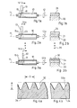
- 5 to 8 show various areal distributions of the depressions 32 on the surface of the printing press cylinder 10.
- FIG. 5 shows an example of a two-dimensional distribution with the densest square packing, in which the grid dimensions x and y are the same size in the two coordinate directions and correspond to the upper diameter D of the depressions 32.
- FIG. 6 shows, likewise as an example, a hexagonally closest surface packing of the depressions 32.
- the depressions 32 can also partially overlap at least in the direction of the one coordinate, the grid dimension of two partially overlapping depressions 32 being designated by z. From this, the grid dimensions of the two surface coordinates are calculated as az or bz, where a and b are selectable factors and a can have a value of 1.414, for example, while b can have a value of 0.767, in which case the depressions 32 relative to one another are less than 45 ° are aligned. The resulting overlaps of the depressions 32 are designated 35.
- FIG. 8 shows yet another variant in which the depressions 32 overlap in both coordinate directions, so that overlaps 35 and 36 arise in both coordinate directions.
- the areal arrangements according to FIGS. 5 to 8 can, as already mentioned, be achieved by suitably setting the process parameters. If, for example, the modulation of the laser beam 31 is set to three pulsations per millimeter along the line 15b of FIG. 3a, approximately 800 to 900 depressions 32 per square centimeter are obtained.
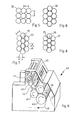
- FIG. 9 shows a known offset printing machine as can be used for printing on sheets or webs.
- the printing press 40 has a printing cylinder 41, a blanket cylinder 42 and a plate cylinder 43.
- An inking unit is denoted by 44 and a dampening unit is denoted by 45.
- the inking unit 44 evenly distributes a certain printing ink onto the surface of the plate cylinder 43 which carries the printing ink.
- the dampening unit 45 with a similar distribution ensures adequate moistening of the surface areas of the plate cylinder 43 provided for this purpose.
- the plate cylinder 43 runs on the blanket cylinder 42 and transfers the image to be printed or the writing to be printed on its elastic surface.
- the blanket cylinder 42 in turn rolls on the sheet or web that is passed between the blanket cylinder 42 and the impression cylinder 41.
- a sheet of paper first reaches the area of the transport cylinder 46 in the direction 47 and is guided from there between the blanket cylinder 42 and the printing cylinder 41. After rotation around the printing cylinder 41, the paper sheet is then conveyed out of the area of the printing unit again in the direction of arrow 48 by means of a further transport cylinder 46 '.
- the surface of the impression cylinder 41 is now provided with the depressions 32, this has the effect that the paper sheet runs in flutter-free along the arrow 47 between the blanket cylinder 42 and the impression cylinder 41 and can also be removed from the impression cylinder 41 without problems releases to be delivered to the second transport cylinder 46 '.
Applications Claiming Priority (2)
| Application Number | Priority Date | Filing Date | Title |
|---|---|---|---|
| DE19853512176 DE3512176A1 (de) | 1985-04-03 | 1985-04-03 | Verfahren zur oberflaechenbehandlung eines druckmaschinenzylinders |
| DE3512176 | 1985-04-03 |
Publications (1)
| Publication Number | Publication Date |
|---|---|
| EP0199084A1 true EP0199084A1 (fr) | 1986-10-29 |
Family
ID=6267203
Family Applications (2)
| Application Number | Title | Priority Date | Filing Date |
|---|---|---|---|
| EP86103681A Withdrawn EP0199084A1 (fr) | 1985-04-03 | 1986-03-18 | Rouleau et gaine de rouleau d'impression et leur procédé de fabrication |
| EP86103682A Expired - Lifetime EP0197374B1 (fr) | 1985-04-03 | 1986-03-18 | Rouleau et gaine de rouleau d'impression et leur procédé de fabrication |
Family Applications After (1)
| Application Number | Title | Priority Date | Filing Date |
|---|---|---|---|
| EP86103682A Expired - Lifetime EP0197374B1 (fr) | 1985-04-03 | 1986-03-18 | Rouleau et gaine de rouleau d'impression et leur procédé de fabrication |
Country Status (5)
| Country | Link |
|---|---|
| EP (2) | EP0199084A1 (fr) |
| JP (1) | JPS621590A (fr) |
| AT (1) | ATE58559T1 (fr) |
| DD (1) | DD279448A5 (fr) |
| DE (2) | DE3512176A1 (fr) |
Cited By (6)
| Publication number | Priority date | Publication date | Assignee | Title |
|---|---|---|---|---|
| EP0246003A2 (fr) * | 1986-04-30 | 1987-11-19 | Den Norske Stats Oljeselskap A.S. | Revêtement contenant du bioxyde de chrome et son procédé de fabrication |
| DE3808285A1 (de) * | 1988-03-12 | 1989-09-21 | Messer Griesheim Gmbh | Verfahren zur herstellung harter und verschleissfester oberflaechenschichten |
| US4963404A (en) * | 1986-05-01 | 1990-10-16 | Stork Screens B.V. | Process for the production of a coated product, thin-walled coated cylinder obtained by using said process, and an ink transfer roller comprising such a cylinder |
| EP0499656A1 (fr) * | 1989-08-17 | 1992-08-26 | Tocalo Co. Ltd. | Rouleau destiné à être utilisé dans un four de traitement thermique et méthode pour sa fabrication |
| FR2692596A1 (fr) * | 1992-06-22 | 1993-12-24 | Lorraine Laminage | Tôle revêtue et procédé de fabrication de cette tôle. |
| AT404905B (de) * | 1990-08-03 | 1999-03-25 | Andritz Ag Maschf | Anlage zum aufbringen einer spritzschicht auf eine ebene oder gekrümmte fläche eines werkstückes |
Families Citing this family (14)
| Publication number | Priority date | Publication date | Assignee | Title |
|---|---|---|---|---|
| CA1287245C (fr) * | 1985-12-20 | 1991-08-06 | Union Carbide Corporation | Surfaces metalliques au carbure resistant a l'usure, gravees au laser, pour cylindres de friction servant a l'ouvraison de pieces longues, production des surfaces, et ouvraison des pieces |
| DE3715327A1 (de) * | 1987-05-08 | 1988-11-17 | Castolin Sa | Verfahren zum herstellen einer verschleissfesten beschichtung |
| EP0305142A1 (fr) * | 1987-08-28 | 1989-03-01 | Corning Glass Works | Procédé pour façonner une pièce à la géométrie désirée |
| DE3821658A1 (de) * | 1988-06-27 | 1989-12-28 | Thyssen Guss Ag | Verfahren zur herstellung von korrosionsbestaendigen und verschleissfesten schichten auf walzen von druckmaschinen |
| DD282248A5 (de) * | 1989-03-03 | 1990-09-05 | Textima Veb K | Streckwerkwalze einer spinnereimaschine |
| US4912824A (en) * | 1989-03-14 | 1990-04-03 | Inta-Roto Gravure, Inc. | Engraved micro-ceramic-coated cylinder and coating process therefor |
| DE4004620C1 (en) * | 1990-02-15 | 1991-09-05 | Du Pont De Nemours (Deutschland) Gmbh, 6380 Bad Homburg, De | Photo-structured layer of three=dimensional object prodn. - by using fusible plastisol or organosol contg. unsatd. monomer, photoinitiator and thermally reactive cpd. |
| JPH0440934U (fr) * | 1990-08-03 | 1992-04-07 | ||
| FR2669846B1 (fr) * | 1990-11-30 | 1994-12-30 | Renault | Procede pour traiter la surface d'un organe mecanique travaillant par frottement. |
| JP3402368B2 (ja) * | 1993-12-27 | 2003-05-06 | アクファーガヴェルト・アクチェンゲゼルシャフト | 親水性の層を疎水性の支持体に適用するための熱処理法およびかくして塗被された支持体のオフセット印刷版の支持体としての使用 |
| DE19914136B4 (de) * | 1999-03-27 | 2009-02-26 | Koenig & Bauer Aktiengesellschaft | Oberfläche für Maschinenteile in Druckmaschinen |
| JP5752473B2 (ja) * | 2011-04-15 | 2015-07-22 | 日鉄住金ハード株式会社 | 輪転機用のローラー及び輪転機用のローラーの製造方法 |
| EP2535437A1 (fr) * | 2011-06-16 | 2012-12-19 | RH Optronic ApS | Procédé de revêtement au plasma de rouleaux et rouleau revêtu au plasma |
| DE102012102087A1 (de) * | 2012-03-13 | 2013-09-19 | Thermico Gmbh & Co. Kg | Bauteil mit einer metallurgisch angebundenen Beschichtung |
Citations (9)
| Publication number | Priority date | Publication date | Assignee | Title |
|---|---|---|---|---|
| DE410158C (de) * | 1924-02-29 | 1925-02-25 | Robert Hopfelt | Verfahren zur Verhinderung des Verschlackens von Roststaeben, Rostflaechen usw |
| GB992657A (en) * | 1962-10-05 | 1965-05-19 | Wellworthy Ltd | Improvements in or relating to cylinder liners for internal combustion engines |
| FR2209854A1 (fr) * | 1972-12-12 | 1974-07-05 | Skf Ind Trading & Dev | |
| DE2343283A1 (de) * | 1973-08-28 | 1975-04-10 | Metallurg Gmbh | Verfahren zum beschichten von druckwalzen und druckplatten |
| DE2611120A1 (de) * | 1975-03-27 | 1976-10-14 | Plast Elastverarbeitungsmasch | Verfahren zur voll- oder teilpanzerung von foerder- oder plastizierschnecken, vorzugsweise fuer plast- und elastverarbeitungsmaschinen |
| GB2049102A (en) * | 1979-05-03 | 1980-12-17 | Csi Corp | Transfer roll |
| JPS5713166A (en) * | 1980-03-03 | 1982-01-23 | Hitachi Zosen Corp | Manufacture of sprayed base material with high strength |
| EP0095608A2 (fr) * | 1982-06-01 | 1983-12-07 | Belserdruck Chr. Belser GmbH & Co. KG | Rouleau presseur et procédé pour sa fabrication |
| JPS6050156A (ja) * | 1983-08-30 | 1985-03-19 | Toshiba Eng Co Ltd | メツキ式溶射方法 |
Family Cites Families (6)
| Publication number | Priority date | Publication date | Assignee | Title |
|---|---|---|---|---|
| DE7132746U (de) * | 1971-08-27 | 1971-12-02 | Maschinenfabrik Augsburg Nuernberg Ag | Druckwerkszylinder oder -walze fuer eine rotationsdruckmaschine |
| GB1583835A (en) * | 1977-03-28 | 1981-02-04 | Avco Everett Res Lab Inc | Metal surface modification |
| DD136480A1 (de) | 1978-05-26 | 1979-07-11 | Herbert Patzelt | Ein-oder mehrschichtiger mantel fuer bogenfuehrende zylinder |
| DE3023246A1 (de) * | 1979-07-02 | 1981-01-08 | Polygraph Leipzig | Ein- oder mehrschichtiger mantel fuer bogenfuehrende zylinder |
| DD154081A1 (de) * | 1980-12-15 | 1982-02-24 | Heiner Fink | Verfahren zum herstellen von oberflaechenschichten fuer feuchtwalzen |
| FR2508493B1 (fr) * | 1981-06-30 | 1989-04-21 | United Technologies Corp | Procede pour appliquer un revetement de barriere thermique en matiere ceramique tolerant aux contraintes sur un substrat metallique |
-
1985
- 1985-04-03 DE DE19853512176 patent/DE3512176A1/de active Granted
-
1986
- 1986-03-18 DE DE8686103682T patent/DE3675676D1/de not_active Expired - Lifetime
- 1986-03-18 AT AT86103682T patent/ATE58559T1/de not_active IP Right Cessation
- 1986-03-18 EP EP86103681A patent/EP0199084A1/fr not_active Withdrawn
- 1986-03-18 EP EP86103682A patent/EP0197374B1/fr not_active Expired - Lifetime
- 1986-04-02 DD DD86288692A patent/DD279448A5/de not_active IP Right Cessation
- 1986-04-03 JP JP61075681A patent/JPS621590A/ja active Pending
Patent Citations (9)
| Publication number | Priority date | Publication date | Assignee | Title |
|---|---|---|---|---|
| DE410158C (de) * | 1924-02-29 | 1925-02-25 | Robert Hopfelt | Verfahren zur Verhinderung des Verschlackens von Roststaeben, Rostflaechen usw |
| GB992657A (en) * | 1962-10-05 | 1965-05-19 | Wellworthy Ltd | Improvements in or relating to cylinder liners for internal combustion engines |
| FR2209854A1 (fr) * | 1972-12-12 | 1974-07-05 | Skf Ind Trading & Dev | |
| DE2343283A1 (de) * | 1973-08-28 | 1975-04-10 | Metallurg Gmbh | Verfahren zum beschichten von druckwalzen und druckplatten |
| DE2611120A1 (de) * | 1975-03-27 | 1976-10-14 | Plast Elastverarbeitungsmasch | Verfahren zur voll- oder teilpanzerung von foerder- oder plastizierschnecken, vorzugsweise fuer plast- und elastverarbeitungsmaschinen |
| GB2049102A (en) * | 1979-05-03 | 1980-12-17 | Csi Corp | Transfer roll |
| JPS5713166A (en) * | 1980-03-03 | 1982-01-23 | Hitachi Zosen Corp | Manufacture of sprayed base material with high strength |
| EP0095608A2 (fr) * | 1982-06-01 | 1983-12-07 | Belserdruck Chr. Belser GmbH & Co. KG | Rouleau presseur et procédé pour sa fabrication |
| JPS6050156A (ja) * | 1983-08-30 | 1985-03-19 | Toshiba Eng Co Ltd | メツキ式溶射方法 |
Non-Patent Citations (4)
| Title |
|---|
| CHEMICAL ABSTRACTS, Band 92, Nr. 24, Juni 1980, Seite 203, Nr. 201655r, Columbus, Ohio, US; J.D. AYERS et al.: "Consolidation of plasma-sprayed coatings by laser remelting", & PROC. SOC. PHOTO-OPT. INSTRUM. ENG. 1980, 198(Laser Appl. Mater. Process.), 57-64 * |
| CHEMICAL ABSTRACTS, Band 94, Nr. 12, M{rz 1981, Seite 255, Nr. 88021g, Columbus, Ohio, US; J.D. AYERS et al.: "Corrosion behavior of laser consolidated titanium coated steel in sea water", & CORROSION (HOUSTON) 1981, 37(1), 55-7 * |
| PATENTS ABSTRACTS OF JAPAN, Band 6, Nr. 78 (C-102) [956], 15. Mai 1982; & JP - A - 57 13 166 (HITACHI ZOSEN K.K.) 23-01-1982 * |
| PATENTS ABSTRACTS OF JAPAN, Band 9, Nr. 180 (C-293) [1903], 25. Juli 1985; & JP - A - 60 50 156 (TOUSHIBA ENGINEERING K.K.) 19-03-1985 * |
Cited By (9)
| Publication number | Priority date | Publication date | Assignee | Title |
|---|---|---|---|---|
| EP0246003A2 (fr) * | 1986-04-30 | 1987-11-19 | Den Norske Stats Oljeselskap A.S. | Revêtement contenant du bioxyde de chrome et son procédé de fabrication |
| EP0246003A3 (fr) * | 1986-04-30 | 1989-08-09 | Den Norske Stats Oljeselskap A.S. | Revêtement contenant du bioxyde de chrome et son procédé de fabrication |
| US5112698A (en) * | 1986-04-30 | 1992-05-12 | Den Norske Stats Oljeselskap A.S | Ceramic coating |
| US4963404A (en) * | 1986-05-01 | 1990-10-16 | Stork Screens B.V. | Process for the production of a coated product, thin-walled coated cylinder obtained by using said process, and an ink transfer roller comprising such a cylinder |
| DE3808285A1 (de) * | 1988-03-12 | 1989-09-21 | Messer Griesheim Gmbh | Verfahren zur herstellung harter und verschleissfester oberflaechenschichten |
| EP0499656A1 (fr) * | 1989-08-17 | 1992-08-26 | Tocalo Co. Ltd. | Rouleau destiné à être utilisé dans un four de traitement thermique et méthode pour sa fabrication |
| AT404905B (de) * | 1990-08-03 | 1999-03-25 | Andritz Ag Maschf | Anlage zum aufbringen einer spritzschicht auf eine ebene oder gekrümmte fläche eines werkstückes |
| FR2692596A1 (fr) * | 1992-06-22 | 1993-12-24 | Lorraine Laminage | Tôle revêtue et procédé de fabrication de cette tôle. |
| EP0576348A1 (fr) * | 1992-06-22 | 1993-12-29 | Sollac | Tôle revêtue et procédé de fabrication de cette tôle |
Also Published As
| Publication number | Publication date |
|---|---|
| ATE58559T1 (de) | 1990-12-15 |
| DE3675676D1 (de) | 1991-01-03 |
| DD279448A5 (de) | 1990-06-06 |
| DE3512176A1 (de) | 1986-10-09 |
| EP0197374B1 (fr) | 1990-11-22 |
| EP0197374A1 (fr) | 1986-10-15 |
| DE3512176C2 (fr) | 1988-05-19 |
| JPS621590A (ja) | 1987-01-07 |
Similar Documents
| Publication | Publication Date | Title |
|---|---|---|
| EP0199084A1 (fr) | Rouleau et gaine de rouleau d'impression et leur procédé de fabrication | |
| DE3608286C2 (fr) | ||
| DE2446188C3 (de) | Bogenführende Mantelfläche von Gegendruckzylindern oder Bogenüberführungszylindern in Rotationsoffsetdruckmaschinen | |
| DE3336705A1 (de) | Abstreifmesser oder schaber | |
| EP0262475A2 (fr) | Machine pour l'impression | |
| EP0889782B1 (fr) | Procede pour imprimer un materiau support | |
| EP0486855B1 (fr) | Rouleau tramé | |
| DE3336704A1 (de) | Rakel zum gesteuerten auftragen und glaetten einer streichmasse auf einer sich kontinuierlich bewegenden papierbahn | |
| EP1013418B1 (fr) | Dispositif d'encrage | |
| EP0615861B1 (fr) | Procédé pour régler la quantité d'encre transférée par un rouleau anilox ainsi que pour rénover des rouleaux anilox usés et construction d'un rouleau anilox qui peut être rénové | |
| EP0182195A2 (fr) | Procédé et appareil pour la fabrication d'écrans par sérigraphie | |
| DE102012006558B4 (de) | Verfahren zur Herstellung einer Flexodruckform | |
| EP0588091A1 (fr) | Blanchet de revêtement pour un cylindre de contre-pression d'une rotative offset recto-verso à feuilles | |
| DE2348717B1 (de) | Verfahren zur Erhoehung der Benetzbarkeit von feuchtmittelfuehrenden Flaechen in Druckmaschinen | |
| CH652347A5 (de) | Vorrichtung zum aufbringen eines fluessigen bzw. halbfluessigen mediums auf die druckplatte einer druckmaschine, insbesondere offsetdruckmaschine. | |
| EP1466729B1 (fr) | Cylindre pour une machine à imprimer et procédé pour la production d'un cylindre | |
| AT500267A1 (de) | Verfahren zum strukturieren von endlosen bändern für pressen | |
| DE3127880A1 (de) | "farbwerk" | |
| DE2363678A1 (de) | Leitwalze fuer druckmaschinen, sowie verfahren zur herstellung einer leitwalze und vorrichtung zur durchfuehrung des verfahrens | |
| DE3211454C2 (de) | Rollenrotationsdruckmaschine für Endlosdruck | |
| DE102015202048B3 (de) | Verfahren zum Bearbeiten einer Offsetdruckplatte und Offsetdruckmaschine | |
| DE2048000C (de) | Druckform für das Hochdruckverfahren | |
| DE2048000A1 (de) | Druckform für das Hochdruckverfahren | |
| DE102010007648A1 (de) | Farbwerk einer Druckmaschine | |
| DE102006021314A1 (de) | Bedruckstoff führende Oberfläche mit Mikro-Erhebungen |
Legal Events
| Date | Code | Title | Description |
|---|---|---|---|
| PUAI | Public reference made under article 153(3) epc to a published international application that has entered the european phase |
Free format text: ORIGINAL CODE: 0009012 |
|
| AK | Designated contracting states |
Kind code of ref document: A1 Designated state(s): AT BE CH DE FR GB IT LI LU NL SE |
|
| STAA | Information on the status of an ep patent application or granted ep patent |
Free format text: STATUS: THE APPLICATION IS DEEMED TO BE WITHDRAWN |
|
| 18D | Application deemed to be withdrawn |
Effective date: 19870630 |