EP0199084A1 - Printing roller and a method of manufacturing the surface of a printing roller - Google Patents
Printing roller and a method of manufacturing the surface of a printing roller Download PDFInfo
- Publication number
- EP0199084A1 EP0199084A1 EP86103681A EP86103681A EP0199084A1 EP 0199084 A1 EP0199084 A1 EP 0199084A1 EP 86103681 A EP86103681 A EP 86103681A EP 86103681 A EP86103681 A EP 86103681A EP 0199084 A1 EP0199084 A1 EP 0199084A1
- Authority
- EP
- European Patent Office
- Prior art keywords
- corrosion
- resistant
- layer
- resistant layer
- abrasion
- Prior art date
- Legal status (The legal status is an assumption and is not a legal conclusion. Google has not performed a legal analysis and makes no representation as to the accuracy of the status listed.)
- Withdrawn
Links
- 238000007639 printing Methods 0.000 title claims abstract description 69
- 238000004519 manufacturing process Methods 0.000 title description 2
- 238000000034 method Methods 0.000 claims abstract description 80
- 238000005260 corrosion Methods 0.000 claims abstract description 37
- 230000007797 corrosion Effects 0.000 claims abstract description 37
- 239000000463 material Substances 0.000 claims abstract description 24
- 239000007921 spray Substances 0.000 claims description 33
- 238000005299 abrasion Methods 0.000 claims description 29
- 230000008018 melting Effects 0.000 claims description 17
- 238000002844 melting Methods 0.000 claims description 17
- OGIDPMRJRNCKJF-UHFFFAOYSA-N titanium oxide Inorganic materials [Ti]=O OGIDPMRJRNCKJF-UHFFFAOYSA-N 0.000 claims description 11
- GWEVSGVZZGPLCZ-UHFFFAOYSA-N Titan oxide Chemical compound O=[Ti]=O GWEVSGVZZGPLCZ-UHFFFAOYSA-N 0.000 claims description 10
- TWNQGVIAIRXVLR-UHFFFAOYSA-N oxo(oxoalumanyloxy)alumane Chemical compound O=[Al]O[Al]=O TWNQGVIAIRXVLR-UHFFFAOYSA-N 0.000 claims description 10
- WGLPBDUCMAPZCE-UHFFFAOYSA-N Trioxochromium Chemical compound O=[Cr](=O)=O WGLPBDUCMAPZCE-UHFFFAOYSA-N 0.000 claims description 9
- 229910000423 chromium oxide Inorganic materials 0.000 claims description 9
- 229910017052 cobalt Inorganic materials 0.000 claims description 9
- 239000010941 cobalt Substances 0.000 claims description 9
- GUTLYIVDDKVIGB-UHFFFAOYSA-N cobalt atom Chemical compound [Co] GUTLYIVDDKVIGB-UHFFFAOYSA-N 0.000 claims description 9
- 239000000919 ceramic Substances 0.000 claims description 7
- UFGZSIPAQKLCGR-UHFFFAOYSA-N chromium carbide Chemical compound [Cr]#C[Cr]C#[Cr] UFGZSIPAQKLCGR-UHFFFAOYSA-N 0.000 claims description 6
- 229910003470 tongbaite Inorganic materials 0.000 claims description 6
- UONOETXJSWQNOL-UHFFFAOYSA-N tungsten carbide Chemical compound [W+]#[C-] UONOETXJSWQNOL-UHFFFAOYSA-N 0.000 claims description 6
- 229910052751 metal Inorganic materials 0.000 claims description 5
- 239000002184 metal Substances 0.000 claims description 5
- 229910052750 molybdenum Inorganic materials 0.000 claims description 4
- 229910052759 nickel Inorganic materials 0.000 claims description 4
- 238000004381 surface treatment Methods 0.000 claims description 4
- DJOYTAUERRJRAT-UHFFFAOYSA-N 2-(n-methyl-4-nitroanilino)acetonitrile Chemical compound N#CCN(C)C1=CC=C([N+]([O-])=O)C=C1 DJOYTAUERRJRAT-UHFFFAOYSA-N 0.000 claims description 3
- ZOKXTWBITQBERF-UHFFFAOYSA-N Molybdenum Chemical compound [Mo] ZOKXTWBITQBERF-UHFFFAOYSA-N 0.000 claims description 3
- 229910052782 aluminium Inorganic materials 0.000 claims description 3
- 229910052804 chromium Inorganic materials 0.000 claims description 3
- 239000011651 chromium Substances 0.000 claims description 3
- 239000011733 molybdenum Substances 0.000 claims description 3
- 229910001151 AlNi Inorganic materials 0.000 claims description 2
- -1 CrNi Inorganic materials 0.000 claims description 2
- 238000007750 plasma spraying Methods 0.000 abstract description 3
- 239000010410 layer Substances 0.000 description 71
- 238000009826 distribution Methods 0.000 description 4
- 230000000694 effects Effects 0.000 description 4
- 238000007645 offset printing Methods 0.000 description 4
- 239000000976 ink Substances 0.000 description 3
- PXHVJJICTQNCMI-UHFFFAOYSA-N nickel Substances [Ni] PXHVJJICTQNCMI-UHFFFAOYSA-N 0.000 description 3
- 238000012856 packing Methods 0.000 description 3
- 238000010586 diagram Methods 0.000 description 2
- 239000004922 lacquer Substances 0.000 description 2
- 239000004033 plastic Substances 0.000 description 2
- 239000005871 repellent Substances 0.000 description 2
- 239000000126 substance Substances 0.000 description 2
- 239000002344 surface layer Substances 0.000 description 2
- 238000012546 transfer Methods 0.000 description 2
- 230000007704 transition Effects 0.000 description 2
- 241001133287 Artocarpus hirsutus Species 0.000 description 1
- 229910000990 Ni alloy Inorganic materials 0.000 description 1
- 229910003310 Ni-Al Inorganic materials 0.000 description 1
- NPXOKRUENSOPAO-UHFFFAOYSA-N Raney nickel Chemical compound [Al].[Ni] NPXOKRUENSOPAO-UHFFFAOYSA-N 0.000 description 1
- 239000000853 adhesive Substances 0.000 description 1
- 230000001070 adhesive effect Effects 0.000 description 1
- 239000012790 adhesive layer Substances 0.000 description 1
- 229910045601 alloy Inorganic materials 0.000 description 1
- 239000000956 alloy Substances 0.000 description 1
- 239000003795 chemical substances by application Substances 0.000 description 1
- 239000011248 coating agent Substances 0.000 description 1
- 238000000576 coating method Methods 0.000 description 1
- 230000003292 diminished effect Effects 0.000 description 1
- 238000005530 etching Methods 0.000 description 1
- 230000005496 eutectics Effects 0.000 description 1
- 238000002474 experimental method Methods 0.000 description 1
- 239000011888 foil Substances 0.000 description 1
- 238000013532 laser treatment Methods 0.000 description 1
- 239000007788 liquid Substances 0.000 description 1
- 229910000907 nickel aluminide Inorganic materials 0.000 description 1
- 230000035515 penetration Effects 0.000 description 1
- 239000011148 porous material Substances 0.000 description 1
- 238000012545 processing Methods 0.000 description 1
- 230000001737 promoting effect Effects 0.000 description 1
- 230000010349 pulsation Effects 0.000 description 1
- 238000005096 rolling process Methods 0.000 description 1
- 238000007789 sealing Methods 0.000 description 1
- 239000000758 substrate Substances 0.000 description 1
- 230000009897 systematic effect Effects 0.000 description 1
- 230000002123 temporal effect Effects 0.000 description 1
Images
Classifications
-
- B—PERFORMING OPERATIONS; TRANSPORTING
- B41—PRINTING; LINING MACHINES; TYPEWRITERS; STAMPS
- B41N—PRINTING PLATES OR FOILS; MATERIALS FOR SURFACES USED IN PRINTING MACHINES FOR PRINTING, INKING, DAMPING, OR THE LIKE; PREPARING SUCH SURFACES FOR USE AND CONSERVING THEM
- B41N7/00—Shells for rollers of printing machines
-
- C—CHEMISTRY; METALLURGY
- C23—COATING METALLIC MATERIAL; COATING MATERIAL WITH METALLIC MATERIAL; CHEMICAL SURFACE TREATMENT; DIFFUSION TREATMENT OF METALLIC MATERIAL; COATING BY VACUUM EVAPORATION, BY SPUTTERING, BY ION IMPLANTATION OR BY CHEMICAL VAPOUR DEPOSITION, IN GENERAL; INHIBITING CORROSION OF METALLIC MATERIAL OR INCRUSTATION IN GENERAL
- C23C—COATING METALLIC MATERIAL; COATING MATERIAL WITH METALLIC MATERIAL; SURFACE TREATMENT OF METALLIC MATERIAL BY DIFFUSION INTO THE SURFACE, BY CHEMICAL CONVERSION OR SUBSTITUTION; COATING BY VACUUM EVAPORATION, BY SPUTTERING, BY ION IMPLANTATION OR BY CHEMICAL VAPOUR DEPOSITION, IN GENERAL
- C23C28/00—Coating for obtaining at least two superposed coatings either by methods not provided for in a single one of groups C23C2/00 - C23C26/00 or by combinations of methods provided for in subclasses C23C and C25C or C25D
-
- C—CHEMISTRY; METALLURGY
- C23—COATING METALLIC MATERIAL; COATING MATERIAL WITH METALLIC MATERIAL; CHEMICAL SURFACE TREATMENT; DIFFUSION TREATMENT OF METALLIC MATERIAL; COATING BY VACUUM EVAPORATION, BY SPUTTERING, BY ION IMPLANTATION OR BY CHEMICAL VAPOUR DEPOSITION, IN GENERAL; INHIBITING CORROSION OF METALLIC MATERIAL OR INCRUSTATION IN GENERAL
- C23C—COATING METALLIC MATERIAL; COATING MATERIAL WITH METALLIC MATERIAL; SURFACE TREATMENT OF METALLIC MATERIAL BY DIFFUSION INTO THE SURFACE, BY CHEMICAL CONVERSION OR SUBSTITUTION; COATING BY VACUUM EVAPORATION, BY SPUTTERING, BY ION IMPLANTATION OR BY CHEMICAL VAPOUR DEPOSITION, IN GENERAL
- C23C4/00—Coating by spraying the coating material in the molten state, e.g. by flame, plasma or electric discharge
- C23C4/02—Pretreatment of the material to be coated, e.g. for coating on selected surface areas
-
- C—CHEMISTRY; METALLURGY
- C23—COATING METALLIC MATERIAL; COATING MATERIAL WITH METALLIC MATERIAL; CHEMICAL SURFACE TREATMENT; DIFFUSION TREATMENT OF METALLIC MATERIAL; COATING BY VACUUM EVAPORATION, BY SPUTTERING, BY ION IMPLANTATION OR BY CHEMICAL VAPOUR DEPOSITION, IN GENERAL; INHIBITING CORROSION OF METALLIC MATERIAL OR INCRUSTATION IN GENERAL
- C23C—COATING METALLIC MATERIAL; COATING MATERIAL WITH METALLIC MATERIAL; SURFACE TREATMENT OF METALLIC MATERIAL BY DIFFUSION INTO THE SURFACE, BY CHEMICAL CONVERSION OR SUBSTITUTION; COATING BY VACUUM EVAPORATION, BY SPUTTERING, BY ION IMPLANTATION OR BY CHEMICAL VAPOUR DEPOSITION, IN GENERAL
- C23C4/00—Coating by spraying the coating material in the molten state, e.g. by flame, plasma or electric discharge
- C23C4/04—Coating by spraying the coating material in the molten state, e.g. by flame, plasma or electric discharge characterised by the coating material
- C23C4/10—Oxides, borides, carbides, nitrides or silicides; Mixtures thereof
-
- C—CHEMISTRY; METALLURGY
- C23—COATING METALLIC MATERIAL; COATING MATERIAL WITH METALLIC MATERIAL; CHEMICAL SURFACE TREATMENT; DIFFUSION TREATMENT OF METALLIC MATERIAL; COATING BY VACUUM EVAPORATION, BY SPUTTERING, BY ION IMPLANTATION OR BY CHEMICAL VAPOUR DEPOSITION, IN GENERAL; INHIBITING CORROSION OF METALLIC MATERIAL OR INCRUSTATION IN GENERAL
- C23C—COATING METALLIC MATERIAL; COATING MATERIAL WITH METALLIC MATERIAL; SURFACE TREATMENT OF METALLIC MATERIAL BY DIFFUSION INTO THE SURFACE, BY CHEMICAL CONVERSION OR SUBSTITUTION; COATING BY VACUUM EVAPORATION, BY SPUTTERING, BY ION IMPLANTATION OR BY CHEMICAL VAPOUR DEPOSITION, IN GENERAL
- C23C4/00—Coating by spraying the coating material in the molten state, e.g. by flame, plasma or electric discharge
- C23C4/18—After-treatment
-
- B—PERFORMING OPERATIONS; TRANSPORTING
- B41—PRINTING; LINING MACHINES; TYPEWRITERS; STAMPS
- B41N—PRINTING PLATES OR FOILS; MATERIALS FOR SURFACES USED IN PRINTING MACHINES FOR PRINTING, INKING, DAMPING, OR THE LIKE; PREPARING SUCH SURFACES FOR USE AND CONSERVING THEM
- B41N2207/00—Location or type of the layers in shells for rollers of printing machines
- B41N2207/02—Top layers
-
- B—PERFORMING OPERATIONS; TRANSPORTING
- B41—PRINTING; LINING MACHINES; TYPEWRITERS; STAMPS
- B41N—PRINTING PLATES OR FOILS; MATERIALS FOR SURFACES USED IN PRINTING MACHINES FOR PRINTING, INKING, DAMPING, OR THE LIKE; PREPARING SUCH SURFACES FOR USE AND CONSERVING THEM
- B41N2207/00—Location or type of the layers in shells for rollers of printing machines
- B41N2207/10—Location or type of the layers in shells for rollers of printing machines characterised by inorganic compounds, e.g. pigments
Definitions
- the invention relates to a method for the surface treatment of a printing press cylinder in which one or preferably more adhesion - promoting, corrosion-resistant or abrasion-resistant layers are applied to the running surface of the cylinder in a plasma spraying process.
- the invention further relates to a printing press cylinder on the Surface of the roller base material is provided with one or more adhesion-promoting, corrosion-resistant or abrasion-resistant layers.
- the invention relates to the use of a method or a printing press cylinder of the aforementioned type.
- each printing unit of an offset printing machine has a so-called inking unit for printing on sheets or webs, i.e. a plurality of rollers rolling on each other, which serve to distribute a color supplied from a container evenly over the running surface of the rollers.
- the color is then applied to a so-called plate cylinder, i.e. transfer the cylinder carrying the printing form, for example a foil or a metal plate.
- the writing to be printed or the image to be printed are formed in that the non-image areas are water-absorbing and ink-repellent, while the image areas are water-repellent and ink-absorbing.
- a so-called dampening system is used to moisten these areas.
- the plate cylinder in turn rolls on the so-called blanket cylinder, i.e. a cylinder covered with a rubber blanket, which prints the image transferred from the plate cylinder onto the paper by means of indirect printing.
- the paper is pressed against the blanket cylinder by the so-called impression cylinder.
- DD-PS 154 081 for the production of surface layers for dampening rollers, in which a wear-resistant, abrasion-resistant and water-friendly surface layer is applied to a base body in the plasma spray process, which is then treated with a nonwoven so that the Support points are broken or rounded and finally the entire surface is polished and cleaned.
- GB-OS 2 100 621 which provides for a ceramic layer to be applied to a substrate using the plasma spray method and for this ceramic layer to be partially melted subsequently by means of a laser.
- the invention is therefore based on the object of developing a method, a printing press cylinder or a use of the type mentioned in such a way that the layers applied in the plasma spraying process to printing press cylinders while retaining the advantage of a non-porous surface adhere much better than is the case with known methods of This is the case and that the paper is guided without problems when entering and exiting the printing zone, in particular without fluttering and without excessive peeling forces in the paper web or in the printing sheet.
- the corrosion-resistant layer is not only applied in a manner known per se in the plasma spray process, but rather the entire surface is melted onto the base material of the roller, which increases both the adhesion to the base material and a smooth surface.
- the object on which the invention is based is further achieved in that finely divided depressions are melted into the outermost layer.
- the object is first achieved in that the layers are melted over the entire surface.
- the object is further achieved in that the top layer is provided with grid-like depressions of about 0.05 to 0.5 mm depth and about 0.1 to 0.5 mm upper diameter.
- the object is achieved with the use mentioned at the outset in that the said method or the press cylinder is used in a blanket, plate or impression cylinder of a web or sheet-fed offset machine.
- the task is completely solved in this way, because the melted-in finely distributed depressions automatically form an effective air cushion between the paper and the cylinder in question, which causes the paper to flutter as it enters the printing zone and excessive release forces when it exits the printing zone certainly diminished.
- the particular advantage of the invention lies in the fact that, while maintaining the print, even the finest grid or grid forms, an air space is created between the cylinder jacket and the printed sheet, which ensures easy detachment of the printed sheet after printing and a flutter-free entry of the printed sheet into the printing zone, in particular for printing cylinders in sheetfed offset, in face or reverse printing.
- a first, adhesion-promoting and corrosion-resistant layer preferably consists of Cr, Ni, Al, CrNi, AlNi, CrAl or the like. It preferably has a thickness of 15 to 100 ⁇ m.
- a further, abrasion-resistant layer is preferably designed according to the invention either as a ceramic layer which consists of aluminum oxide, titanium oxide, chromium oxide, aluminum oxide + chromium oxide, aluminum oxide + titanium oxide, chromium oxide + titanium oxide, chromium carbide, chromium carbide + cobalt, tungsten carbide, tungsten carbide cobalt, calcium zirconate or the like it is a metal layer made of molybdenum, cobalt or the like.
- the abrasion-resistant layer is preferably applied in a thickness of 60 to 300 ⁇ , preferably 200 p.
- the layers are melted over the entire surface by means of a laser or the depressions are melted into the outermost layer.
- the known use of a laser for melting the layer or layers in the application of interest here in printing press cylinders has the essential advantage that, despite a point-by-point impact point of the laser beam, printing press cylinders with relatively large dimensions are also completely melted can be covered by a slow rotation of the printing press cylinder and by an equally slow axial advance of the laser, a spiral with a very small pitch on the outer circumference of the printing press cylinder is swept, which is so narrow that the laser beam gradually sweeps the entire surface.
- the use of a laser also has the advantage that the penetration depth during melting can be suitably set by using suitable lasers. A particularly good effect is achieved in this context by simultaneously melting the outermost layer by means of the laser and melting the depressions in one operation.
- this is achieved by rotating the printing press cylinder around its longitudinal axis at a constant, slow speed to melt the depressions, and at the same time moving the laser parallel to the longitudinal axis by means of a slow feed, while a laser beam is directed to the surface of the printing press cylinder and the intensity of the laser beam is modulated.
- An almost arbitrary grid of depressions can then be applied by the pulse duty factor of the modulation in connection with the speed of the printing press cylinder and the feed speed of the laser.
- the shape of the depressions can be determined by suitably adjusting the modulation, in particular by either switching the laser beam back and forth abruptly between minimum and maximum intensity or modulating it with smooth transitions.
- the dynamics too The intensity of the laser beam between maximum and minimum power can be used to form certain shapes of depressions.
- the laser beam is modulated approximately three times per millimeter in length of the line which it describes on the surface of the printing press cylinder.
- the depressions are melted in such a way that they have a sinusoidal or a triangular cross-sectional image in a direction perpendicular to the surface of the layer.
- the depressions are melted in such a way that their upper openings lie against one another at least approximately in a square-dense grid.
- An even denser packing of the depressions on the surface can, however, also be achieved in that they lie against one another in a hexagonally dense grid.
- the openings of the depressions are in at least one another Coordinate direction overlap. In this way it is ensured that the entire surface of the printing press cylinder is subjected to a laser treatment because the zones of subsequent melting of recesses merge into one another.
- the depressions are melted to a depth of approximately 0.05 to 0.5 mm and to a diameter of approximately 0.1 to 0.5 mm.
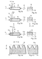
- 1a to 3b show in a simplified representation different steps of the method according to the invention, the same elements being provided with the same reference numerals.
- 1 a to 3 a show a schematic representation of a device for carrying out the method according to the invention, while FIGS. 1 b, 2 b and 3 b show the layer structure achieved in each case in a greatly enlarged representation.
- Fig. 1 is 10 a printing press cylinder which is clamped in a device, not shown, such that it can be rotated about its longitudinal axis 11 in the direction of arrow 12 at a very slow speed.
- a plasma spray gun 13 in a radial orientation, which can be slowly adjusted in the direction of an arrow 14 parallel to the longitudinal axis 11 of the printing press cylinder 10 by means of a feed, also not shown.
- FIG. 1a a spiral line on the surface of the printing press cylinder 10 is indicated in FIG. 1a.
- a first material 16, which emerges from the plasma spray gun 13, is distributed along this line 15 when the printing press cylinder 10 and the plasma spray gun 13 move in the manner described. It is easy to see that the slope of the spiral line 15 can be adjusted as desired by adjusting the speed of the press cylinder 10 and the feed speed of the plasma spray gun 13, as well as the speed at which the plasma spray gun 13 along the line 15 moves.
- FIG. 1b shows that a first layer 21 can be applied to a base material 20 of the printing press cylinder 10 in the manner described above.
- the first layer 21 is preferably an adhesion-promoting and corrosion-resistant layer.
- the first material 16, from which the first layer 21 is made can be a material which is suitable for this purpose and can be applied in a plasma spray process, for example Cr, Ni, Al, CrNi; AINi, CrAl or the like
- a second layer 24 is next applied to the adhesion-promoting and corrosion-resistant first layer 21, as shown in FIG. 2b.
- a further process step is carried out, which corresponds to the process step according to FIG. 1a, but with the difference that instead of the first material 16, a second material 23 is sprayed by the plasma spray gun 13.
- a second material 23 is sprayed by the plasma spray gun 13.
- the process parameters in the second process step according to FIG. 2a can differ from those of the first step according to FIG. 1a if this appears advisable due to the specially used second material 23.
- abrasion-resistant material is preferably used as the second material 23 from which the second layer 24 is made.
- this can be a ceramic layer which consists of aluminum oxide or titanium oxide or chromium oxide or aluminum oxide + chromium oxide, aluminum oxide + titanium oxide, chromium oxide + titanium oxide, chromium carbide, chromium carbide + cobalt, tungsten carbide, tungsten carbide cobalt, calcium zirconate or the like.
- a metal layer made of molybdenum, cobalt or the like can also be used as an abrasion-resistant layer.
- adhesion-promoting and corrosion-resistant layers on the one hand and abrasion-resistant layers on the other hand can also be provided several times in succession.
- Points 26 indicate that the first two process steps can be followed by further process steps of a similar type, so that overall a structure with more than two layers 21, 24 is formed on the roller base material 20.
- 3a shows a further method step in a schematic representation, in which, instead of the plasma spray gun 13, a laser 30 is guided parallel to the longitudinal axis 11 of the printing press cylinder 10 by means of a suitable feed.
- the parameters 12b, 14b and 15b corresponding to the previous method steps can be set appropriately again. This is particularly recommended in view of the fact that the slope of the spiral line 15b is set much smaller than was the case for lines 15 and 15a, because the point of incidence of the laser beam 31 of the laser 30 is significantly smaller than the spray zone, which is associated with the plasma spray gun 13 is swept over the surface of the printing press cylinder 10.
- the laser beam 31 can either be switched on and off, i.e. can be clocked, but it can also be adjusted in intensity with smooth transitions between a maximum and a minimum intensity value.
- the depressions 32 according to FIG. 4a have a sinusoidal shape in the vertical cross section, while the depressions 32a according to FIG. 4b have a more triangular shape.
- the depth T of the depressions 32 is approximately 0.05 to 0.5 mm, preferably 0.35 mm and the diameter D is approximately 0.1 to 0.5 mm, preferably 0.11 mm.
- the diameters D and the depths T of the depressions 32 can be varied within wide limits.
- 5 to 8 show various areal distributions of the depressions 32 on the surface of the printing press cylinder 10.
- FIG. 5 shows an example of a two-dimensional distribution with the densest square packing, in which the grid dimensions x and y are the same size in the two coordinate directions and correspond to the upper diameter D of the depressions 32.
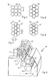
- FIG. 6 shows, likewise as an example, a hexagonally closest surface packing of the depressions 32.
- the depressions 32 can also partially overlap at least in the direction of the one coordinate, the grid dimension of two partially overlapping depressions 32 being designated by z. From this, the grid dimensions of the two surface coordinates are calculated as az or bz, where a and b are selectable factors and a can have a value of 1.414, for example, while b can have a value of 0.767, in which case the depressions 32 relative to one another are less than 45 ° are aligned. The resulting overlaps of the depressions 32 are designated 35.
- FIG. 8 shows yet another variant in which the depressions 32 overlap in both coordinate directions, so that overlaps 35 and 36 arise in both coordinate directions.
- the areal arrangements according to FIGS. 5 to 8 can, as already mentioned, be achieved by suitably setting the process parameters. If, for example, the modulation of the laser beam 31 is set to three pulsations per millimeter along the line 15b of FIG. 3a, approximately 800 to 900 depressions 32 per square centimeter are obtained.
- FIG. 9 shows a known offset printing machine as can be used for printing on sheets or webs.
- the printing press 40 has a printing cylinder 41, a blanket cylinder 42 and a plate cylinder 43.
- An inking unit is denoted by 44 and a dampening unit is denoted by 45.
- the inking unit 44 evenly distributes a certain printing ink onto the surface of the plate cylinder 43 which carries the printing ink.
- the dampening unit 45 with a similar distribution ensures adequate moistening of the surface areas of the plate cylinder 43 provided for this purpose.
- the plate cylinder 43 runs on the blanket cylinder 42 and transfers the image to be printed or the writing to be printed on its elastic surface.
- the blanket cylinder 42 in turn rolls on the sheet or web that is passed between the blanket cylinder 42 and the impression cylinder 41.
- a sheet of paper first reaches the area of the transport cylinder 46 in the direction 47 and is guided from there between the blanket cylinder 42 and the printing cylinder 41. After rotation around the printing cylinder 41, the paper sheet is then conveyed out of the area of the printing unit again in the direction of arrow 48 by means of a further transport cylinder 46 '.
- the surface of the impression cylinder 41 is now provided with the depressions 32, this has the effect that the paper sheet runs in flutter-free along the arrow 47 between the blanket cylinder 42 and the impression cylinder 41 and can also be removed from the impression cylinder 41 without problems releases to be delivered to the second transport cylinder 46 '.
Landscapes
- Chemical & Material Sciences (AREA)
- Engineering & Computer Science (AREA)
- Organic Chemistry (AREA)
- Chemical Kinetics & Catalysis (AREA)
- Materials Engineering (AREA)
- Mechanical Engineering (AREA)
- Metallurgy (AREA)
- Plasma & Fusion (AREA)
- Physics & Mathematics (AREA)
- Printing Plates And Materials Therefor (AREA)
- Coating By Spraying Or Casting (AREA)
- Application Of Or Painting With Fluid Materials (AREA)
- Manufacture Or Reproduction Of Printing Formes (AREA)
- Paper (AREA)
- Registering, Tensioning, Guiding Webs, And Rollers Therefor (AREA)
- Laser Beam Processing (AREA)
Abstract
Description
Die Erfindung betrifft ein Verfahren zur Oberflächenbehandlung eines Druckmaschinenzylinders bei dem auf die Lauffläche des Zylinders eine oder vorzugsweise mehrere haftvermit- telnde, korrosionsbeständige oder abriebfeste Schichten im Plasmasprüh-Verfahren aufgebracht werden. Die Erfindung betrifft ferner einen Druckmaschinenzylinder, der an der Oberfläche des Walzengrundmaterials mit einer oder mehreren haftvermittelnden, korrosionsbeständigen oder abriebfesten Schichten versehen ist. Die Erfindung betrifft schließlich die Verwendung eines Verfahrens oder eines Druckmaschinenzylinders der vorstehend genannten Art.The invention relates to a method for the surface treatment of a printing press cylinder in which one or preferably more adhesion - promoting, corrosion-resistant or abrasion-resistant layers are applied to the running surface of the cylinder in a plasma spraying process. The invention further relates to a printing press cylinder on the Surface of the roller base material is provided with one or more adhesion-promoting, corrosion-resistant or abrasion-resistant layers. Finally, the invention relates to the use of a method or a printing press cylinder of the aforementioned type.
Bekanntlich weist jedes Druckwerk einer Offset-Druckmaschine zum Bedrucken von Bögen oder Bahnen ein sogenanntes Farbwerk auf, d.h. eine Mehrzahl von aufeinander abrollenden Rollen, die dazu dienen, eine aus einem Behälter zugeführte Farbe gleichmäßig über die Lauffläche der Rollen zu verteilen. Die Farbe wird alsdann auf einen sogenannten Plattenzylinder, d.h. den die Druckform, beispielsweise eine Folie oder eine Metallplatte, tragenden Zylinder übertragen.As is known, each printing unit of an offset printing machine has a so-called inking unit for printing on sheets or webs, i.e. a plurality of rollers rolling on each other, which serve to distribute a color supplied from a container evenly over the running surface of the rollers. The color is then applied to a so-called plate cylinder, i.e. transfer the cylinder carrying the printing form, for example a foil or a metal plate.
Die zu druckende Schrift bzw. das zu druckende Bild werden hierbei dadurch gebildet, daß die bildfreien Stellen wasseraufnehmend und farbabstoßend, die Bildstellen dagegen wasserabstoßend und farbaufnehmend sind. Zum Befeuchten dieser Stellen dient ein sogenanntes Feuchtwerk.The writing to be printed or the image to be printed are formed in that the non-image areas are water-absorbing and ink-repellent, while the image areas are water-repellent and ink-absorbing. A so-called dampening system is used to moisten these areas.
Der Plattenzylinder rollt seinerseits auf dem sogenannten Gummituchzylinder, d.h. einem mit einem Gummituch bespannten Zylinder, ab, der im Wege des Indirektdruckes das vom Plattenzylinder übertragene Bild auf das Papier aufdruckt. Das Papier wird dabei vom sogenannten Druckzylinder gegen den Gummituchzylinder gepreßt.The plate cylinder in turn rolls on the so-called blanket cylinder, i.e. a cylinder covered with a rubber blanket, which prints the image transferred from the plate cylinder onto the paper by means of indirect printing. The paper is pressed against the blanket cylinder by the so-called impression cylinder.
Aus dem eingangs genannten DE-GM 71 32 746 ist es nun bekannt, den beim Offsetdrucken einwirkenden chemischen und mechanischen Belastungen dadurch zu begegnen, daß auf die Zylinder eine verschleiß- und korrosionsbeständige Oberfläche aufgebracht wird. Hierzu sieht das bekannte Verfahren vor, auf das Walzengrundmaterial eine Zwischenschicht aus Nickelaluminid und darauf eine Panzerschicht aus Aluminiumoxid mit Titanoxid im Plasmasprüh-Verfahren aufzubringen.From the above-mentioned DE-GM 71 32 746 it is now known to counteract the chemical and mechanical loads acting in offset printing in that the Cylinder a wear and corrosion resistant surface is applied. For this purpose, the known method provides for an intermediate layer of nickel aluminide to be applied to the base material of the roller, and a layer of armor made of aluminum oxide with titanium oxide in a plasma spray process.
Obwohl hierdurch eine gute Korrosionsbeständigkeit im Hinblick auf die beim Ätzen der Druckplatte verwendeten Mittel oder aggressive Feuchtmittel oder Farben erreicht wird, ebenso wie eine Verschleißfestigkeit an den Laufflächen der Walzen, so hat doch das Aufbringen dieser Schichten im Plasmasprüh-Verfahren zwei systematische Nachteile:
- Zum einen haftet eine im Plasmasprüh-Verfahren aufgebrachte Schicht von beispielsweise 50 µ Dicke auf dem Grundmaterial nur durch reine Adhäsion, so daß prinzipiell stets die Gefahr des Abblätterns der aufgesprühten Schicht besteht.
- On the one hand, a layer applied in the plasma spray process, for example 50 .mu.m thick, adheres to the base material only by pure adhesion, so that in principle there is always the risk of the sprayed-on layer peeling off.
Ein weiterer Nachteil ist, daß eine im Plasmasprüh-Verfahren aufgebrachte Keramik- oder Legierungsschicht stets porös ist, so daß Chemikalien in die Poren eindringen können. Es ist zwar aus der DE-PS 31 43 874 bekannt, die poröse Beschichtung mit einem flüssigen vernetzbaren Kunststoff oder Lack zu tränken und den Kunststoff bzw. Lack anschließend durch Elektronen zu vernetzen bzw. in einem Vakuum zu härten (DE-PS 33 16 348), aber selbst dieses Versiegelungsverfahren hat für bestimmte Anwendungsfälle seine Grenzen und löst das zuvor genannte Problem der Adhäsionshaftung nicht.Another disadvantage is that a ceramic or alloy layer applied in the plasma spray process is always porous, so that chemicals can penetrate into the pores. It is known from DE-PS 31 43 874 to soak the porous coating with a liquid cross-linkable plastic or lacquer and then to cross-link the plastic or lacquer with electrons or to harden it in a vacuum (DE-PS 33 16 348 ), but even this sealing process has its limits for certain applications and does not solve the aforementioned problem of adhesion liability.
Aus der DE-PS 23 43 283 ist es weiterhin bekannt, das Plas- maspritzen von oxidkeramischen Schichten aus A1 203 und 1 bis 50% Ti02 sowie von hitzebeständigen Haftschichten aus Ni, Mo, Ni-Al- oder Cr-Ni-Legierungen zur Verhinderung der elektrolytischen Spannungskorrosion von Druckwalzen und Druckplatten zu verwenden. Auch diese bekannte Verwendung löst jedoch das vorstehend geschilderte Problem nicht, weil der Haftmechanismus dieser bekannten Schichten unverändert ist.From DE-PS 23 43 283 it is also known that plasma mas p r n it ze of ceramic oxide layers of A1 2 0 3 and 1 to 50% Ti0 2 and heat-resistant adhesive layers of Use Ni, Mo, Ni-Al or Cr-Ni alloys to prevent electrolytic stress corrosion of printing rollers and printing plates. However, this known use does not solve the problem described above, because the adhesive mechanism of these known layers is unchanged.
Entsprechendes gilt für ein aus der DD-PS 154 081 bekanntes Verfahren zum Herstellen von Oberflächenschichten für Feuchtwalzen, bei dem auf einen Grundkörper im Plasmasprüh-Verfahren eine verschleißfeste, abriebfeste und wasserfreundliche Oberflächenschicht aufgebracht wird, die danach mit einem Vlies nachbehandelt wird, so daß die Tragpunkte gebrochen oder gerundet werden und schließlich die gesamte Oberfläche poliert und gesäubert wird.The same applies to a method known from DD-PS 154 081 for the production of surface layers for dampening rollers, in which a wear-resistant, abrasion-resistant and water-friendly surface layer is applied to a base body in the plasma spray process, which is then treated with a nonwoven so that the Support points are broken or rounded and finally the entire surface is polished and cleaned.
Aus der DE-OS 28 13 707 ist es ferner allgemein bekannt, Metalloberflächen mittels eines Lasers aufzuheizen und zu schmelzen, um ein eutektisches Gefüge des Oberflächenmaterials zu erreichen.From DE-OS 28 13 707 it is also generally known to heat and melt metal surfaces by means of a laser in order to achieve a eutectic structure of the surface material.
Entsprechendes gilt für ein Verfahren, wie es allgemein in der GB-OS 2 100 621 beschrieben ist, das vorsieht, eine Keramikschicht im Plasmasprüh-Verfahren auf ein Substrat aufzubringen und diese Keramikschicht anschließend mittels eines Lasers teilweise zu schmelzen.The same applies to a method, as is generally described in GB-OS 2 100 621, which provides for a ceramic layer to be applied to a substrate using the plasma spray method and for this ceramic layer to be partially melted subsequently by means of a laser.
Es hat sich ferner gezeigt, daß bekannte Druckmaschinen gelegentlich Probleme bereiten, weil Druckbögen flatternd in die Druckzone einlaufen und sich auch nach dem Druck vom Druckzylinder nicht leicht lösen. Um diesem Problem zu begegnen, ist es bekannt, im Bereich des Druckzylinders netzartige Matten vorzusehen, mit denen eine Art Luftpolster zwischen den Druckbögen und dem Druckzylinder gebildet wird.It has also been found that known printing machines occasionally cause problems because printed sheets flutter into the printing zone and are not easily detached from the printing cylinder even after printing. To counter this problem, it is known in the area of the impression cylinder to provide mesh-like mats with which a kind of air cushion is formed between the printing sheets and the printing cylinder.
Diese netzartigen Matten sind jedoch einem hohen Verschleiß ausgesetzt und sehr umständlich in der Handhabung.However, these mesh-like mats are subject to high wear and very cumbersome to use.
Ähnliche Probleme treten bei anderen Konfigurationen von Druckmaschinen auf.Similar problems occur with other press configurations.
Der Erfindung liegt daher die Aufgabe zugrunde, ein Verfahren, einen Druckmaschinenzylinder bzw. eine Verwendung der eingangs genannten Art dahingehend weiterzubilden, daß die im Plasmasprüh-Verfahren auf Druckmaschinenzylinder aufgebrachten Schichten unter Beibehaltung des Vorteils einer unporösen Oberfläche wesentlich besser haften als dies bei bekannten Verfahren der Fall ist und daß die Papierführung beim Einlaufen in die Druckzone und beim Auslaufen aus der Druckzone problemlos, insbesondere ohne Flattern und ohne zu große Ablösekräfte in der Papierbahn bzw. im Druckbogen erfolgt.The invention is therefore based on the object of developing a method, a printing press cylinder or a use of the type mentioned in such a way that the layers applied in the plasma spraying process to printing press cylinders while retaining the advantage of a non-porous surface adhere much better than is the case with known methods of This is the case and that the paper is guided without problems when entering and exiting the printing zone, in particular without fluttering and without excessive peeling forces in the paper web or in the printing sheet.
Gemäß dem eingangs genannten Verfahren wird diese Aufgabe zum einen durch die Verfahrensschritte:
- a) Aufbringen einer korrosionsbeständigen Schicht im Plasmasprüh-Verfahren;
- b) vollflächiges Aufschmelzen der korrosionsbeständigen Schicht,
- a) applying a corrosion-resistant layer in the plasma spray process;
- b) full-surface melting of the corrosion-resistant layer,
Im Gegensatz zu den bekannten Verfahren wird nämlich nicht nur in an sich bekannter Weise die korrosionsbeständige Schicht im Plasmasprüh-Verfahren aufgebracht, sondern die Schicht wird vielmehr vollflächig auf das Walzengrundmaterial aufgeschmolzen, wodurch sowohl die Haftung am Grundmaterial erhöht wie auch eine glatte Oberfläche erzeugt wird.In contrast to the known methods, the corrosion-resistant layer is not only applied in a manner known per se in the plasma spray process, but rather the entire surface is melted onto the base material of the roller, which increases both the adhesion to the base material and a smooth surface.
Diese Wirkung wird noch wesentlich durch die weiteren Verfahrensschritte
- c) Aufbringen einer abriebfesten Schicht im Plasmasprüh-Verfahren auf die aufgeschmolzene korrosionsbeständige Schicht;
- d) vollflächiges Aufschmelzen der abriebfesten Schicht,
gesteigert, weil nun eine zweilagige Schicht mit hoher Haftung und glatter Oberfläche auf das Walzengrundmaterial aufgeschmolzen ist, deren untere, auf dem Walzengrundmaterial aufliegende Lage das Grundmaterial vor Korrosion schützt, während die obere, abriebfeste Lage den Druckmaschinenzylinder vor Verschleiß schützt.This effect becomes even more important through the further process steps
- c) applying an abrasion-resistant layer in a plasma spray process to the melted, corrosion-resistant layer;
- d) full-surface melting of the abrasion-resistant layer,
increased because a two-layer layer with high adhesion and a smooth surface has now melted onto the roller base material, the lower layer on which the roller base material protects the base material from corrosion, while the upper, abrasion-resistant layer protects the printing press cylinder from wear.
Erfindungsgemäß kann die angestrebte Wirkung noch weiter durch die folgenden Verfahrensschritte
- e) Aufbringen einer zweiten korrosionsbeständigen Schicht im Plasmasprüh-Verfahren auf die aufgeschmolzene abriebfeste Schicht;
- f) Aufbringen einer zweiten abriebfesten Schicht im Plasmasprüh-Verfahren auf die zweite korrosionsbeständige Schicht;
- g) vollflächiges Aufschmelzen der zweiten korrosionsbeständigen und der zweiten abriebfesten Schicht,
gesteigert werden, weil nun ein insgesamt vierlagiger Schichtaufbau besteht, bei dem ein Verfahrensschritt durch gemeinsames Aufschmelzen der beiden obersten Schichten gespart wird.According to the invention, the desired effect can be further increased by the following process steps
- e) applying a second corrosion-resistant layer in a plasma spray process onto the melted abrasion-resistant layer;
- f) applying a second abrasion-resistant layer to the second corrosion-resistant layer using the plasma spray method;
- g) full-surface melting of the second corrosion-resistant and the second abrasion-resistant layer,
be increased because there is now a total of four layers, in which one process step is saved by melting the two uppermost layers together.
Bei manchen Anwendungsfällen genügen erfindungsgemäß die folgenden Verfahrensschritte:
- a) Aufbringen einer korrosionsbeständigen Schicht im Plasmasprüh-Verfahren;
- b) Aufbringen einer abriebfesten Schicht im Plasmasprüh-Verfahren auf die korrosionsbeständige Schicht;
- c) vollflächiges Aufschmelzen der korrosionsbeständigen und der abriebfesten Schicht.
- a) applying a corrosion-resistant layer in the plasma spray process;
- b) applying an abrasion-resistant layer in a plasma spray process to the corrosion-resistant layer;
- c) full-surface melting of the corrosion-resistant and the abrasion-resistant layer.
Gemäß dem eingangs genannten Verfahren wird die der Erfindung zugrundeliegende Aufgabe ferner dadurch gelöst, daß fein verteilte Vertiefungen in die jeweils äußerste Schicht eingeschmolzen werden.According to the method mentioned at the outset, the object on which the invention is based is further achieved in that finely divided depressions are melted into the outermost layer.
Gemäß dem eingangs genannten Druckmaschinenzylinder wird die Aufgabe zunächst dadurch gelöst, daß die Schichten vollflächig aufgeschmolzen sind.According to the printing press cylinder mentioned in the introduction, the object is first achieved in that the layers are melted over the entire surface.
Gemäß dem eingangs genannten Druckmaschinenzylinder wird die Aufgabe ferner dadurch gelöst, daß die oberste Schicht mit rasterartig verteilten Vertiefungen von etwa 0,05 bis 0,5 mm Tiefe und etwa 0,1 bis 0,5 mm oberem Durchmesser versehen ist.According to the printing press cylinder mentioned in the introduction, the object is further achieved in that the top layer is provided with grid-like depressions of about 0.05 to 0.5 mm depth and about 0.1 to 0.5 mm upper diameter.
Schließlich wird die Aufgabe bei der eingangs genannten Verwendung dadurch gelöst, daß das genannte Verfahren bzw. der genannte Druckmaschinenzylinder bei einem Gummituch-, Platten- oder Druckzylinder einer Rollen- oder Bogenoffsetmaschine verwendet wird.Finally, the object is achieved with the use mentioned at the outset in that the said method or the press cylinder is used in a blanket, plate or impression cylinder of a web or sheet-fed offset machine.
Die Aufgabe wird auf diese Weise vollkommen gelöst, weil sich durch die eingeschmolzenen fein verteilten Vertiefungen von selbst ein wirksames Luftpolster zwischen dem Papier und dem betreffenden Zylinder bildet, das ein Flattern des Papiers beim Einlaufen in die Druckzone und zu hohe Ablösekräfte beim Auslaufen aus der Druckzone sicher vermindert. Der besondere Vorteil der Erfindung liegt dabei somit darin, daß bei Wahrung des Aufdruckes auch feinster Raster oder Rasterformen ein Luftraum zwischen Zylindermantel und Druckbogen geschaffen wird, der ein leichtes Ablösen des Druckbogens nach dem Druck und ein flatterfreies Einlaufen des Druckbogens in die Druckzone sichert, insbesondere bei Druckzylindern im Bogenoffsetverfahren, im Schön- oder Widerdruck.The task is completely solved in this way, because the melted-in finely distributed depressions automatically form an effective air cushion between the paper and the cylinder in question, which causes the paper to flutter as it enters the printing zone and excessive release forces when it exits the printing zone certainly diminished. The particular advantage of the invention lies in the fact that, while maintaining the print, even the finest grid or grid forms, an air space is created between the cylinder jacket and the printed sheet, which ensures easy detachment of the printed sheet after printing and a flutter-free entry of the printed sheet into the printing zone, in particular for printing cylinders in sheetfed offset, in face or reverse printing.
Im Rahmen der vorliegenden Erfindung besteht eine erste, haftvermittelnde und korrosionsbeständige Schicht vorzugsweise aus Cr, Ni, Al, CrNi, AlNi, CrAl o. dgl. Sie weist vorzugsweise eine Dicke von 15 bis 100 µ auf.In the context of the present invention, a first, adhesion-promoting and corrosion-resistant layer preferably consists of Cr, Ni, Al, CrNi, AlNi, CrAl or the like. It preferably has a thickness of 15 to 100 μm.
Eine weitere, abriebfeste Schicht ist erfindungsgemäß bevorzugt entweder als Keramikschicht ausgebildet, die aus Aluminiumoxid, Titanoxid, Chromoxid, Aluminiumoxid + Chromoxid, Aluminiumoxid + Titanoxid, Chromoxid + Titanoxid, Chromkarbid, Chromkarbid + Kobalt, Wolframkarbid, Wolframkarbidkobalt, Kalziumzirkonat o. dgl. besteht oder sie ist eine Metallschicht aus Molybdän, Kobalt o. dgl.A further, abrasion-resistant layer is preferably designed according to the invention either as a ceramic layer which consists of aluminum oxide, titanium oxide, chromium oxide, aluminum oxide + chromium oxide, aluminum oxide + titanium oxide, chromium oxide + titanium oxide, chromium carbide, chromium carbide + cobalt, tungsten carbide, tungsten carbide cobalt, calcium zirconate or the like it is a metal layer made of molybdenum, cobalt or the like.
Die abriebfeste Schicht wird bevorzugt in einer Dicke von 60 bis 300 µ, vorzugsweise von 200 p aufgebracht.The abrasion-resistant layer is preferably applied in a thickness of 60 to 300 μ, preferably 200 p.
Diese Materialien bzw. Dimensionierungen haben sich in praktischen Erprobungen als besonders zweckmäßig erwiesen.These materials and dimensions have proven particularly useful in practical trials.
Bei einer besonders bevorzugten Ausgestaltung des erfindungsgemäßen Verfahrens werden die Schichten mittels eines Lasers vollflächig aufgeschmolzen bzw. die Vertiefungen in die äußerste Schicht eingeschmolzen.In a particularly preferred embodiment of the method according to the invention, the layers are melted over the entire surface by means of a laser or the depressions are melted into the outermost layer.
Die an sich bekannte Verwendung eines Lasers zum Aufschmelzen der Schicht oder Schichten hat im hier interessierenden Anwendungsfall bei Druckmaschinenzylindern den wesentlichen Vorteil, daß trotz eines an sich punktförmigen Auftreffpunktes des Laserstrahls auch Druckmaschinenzylinder mit verhältnismäßig großen Abmessungen vollflächig aufgeschmolzen werden können, indem durch langsames Drehen des Druckmaschinenzylinders und durch einen ebenso langsamen axialen Vorschub des Lasers eine Spirale mit sehr kleiner Steigung am Außenumfang des Druckmaschinenzylinders überstrichen wird, die so eng bemessen ist, daß der Laserstrahl die gesamte Oberfläche nach und nach bestreicht. Die Verwendung eines Lasers hat darüber hinaus den Vorteil, daß durch Verwendung geeigneter Laser die Eindringtiefe beim Aufschmelzen geeignet eingestellt werden kann. Eine besonders gute Wirkung wird in diesem Zusammenhang dadurch erzielt, daß die jeweils äußerste Schicht gleichzeitig mittels des Lasers aufgeschmolzen und in einem Arbeitsgang die Vertiefungen eingeschmolzen werden.The known use of a laser for melting the layer or layers in the application of interest here in printing press cylinders has the essential advantage that, despite a point-by-point impact point of the laser beam, printing press cylinders with relatively large dimensions are also completely melted can be covered by a slow rotation of the printing press cylinder and by an equally slow axial advance of the laser, a spiral with a very small pitch on the outer circumference of the printing press cylinder is swept, which is so narrow that the laser beam gradually sweeps the entire surface. The use of a laser also has the advantage that the penetration depth during melting can be suitably set by using suitable lasers. A particularly good effect is achieved in this context by simultaneously melting the outermost layer by means of the laser and melting the depressions in one operation.
Dies wird bei einer praktischen Auführungsform des erfindungsgemäßen Verfahrens dadurch erreicht, daß zum Einschmelzen der Vertiefungen der Druckmaschinenzylinder, wie bereits erwähnt, mit konstanter, langsamer Drehzahl um seine Längsachse gedreht und gleichzeitig der Laser durch einen langsamen Vorschub parallel zur Längsachse bewegt wird, während ein Laserstrahl auf die Oberfläche des Druckmaschinenzylinders gerichtet ist und der Laserstrahl in seiner Intensität moduliert wird. Es kann dann durch das Tastverhältnis der Modulation in Verbindung mit der Drehzahl des Druckmaschinenzylinders und der Vorschubgeschwindigkeit des Lasers ein nahezu beliebiges Raster von Vertiefungen aufgebracht werden. Die Form der Vertiefungen kann durch geeignetes Einstellen der Modulation bestimmt werden, insbesondere dadurch, daß der Laserstrahl zwischen minimaler und maximaler Intensität entweder schlagartig hin und her geschaltet oder mit weichen Übergängen moduliert wird. Auch die Dynamik der Intensität des Laserstrahls zwischen maximaler und minimaler Leistung kann zur Ausbildung bestimmter Formen von Vertiefungen herangezogen werden.In a practical embodiment of the method according to the invention, this is achieved by rotating the printing press cylinder around its longitudinal axis at a constant, slow speed to melt the depressions, and at the same time moving the laser parallel to the longitudinal axis by means of a slow feed, while a laser beam is directed to the surface of the printing press cylinder and the intensity of the laser beam is modulated. An almost arbitrary grid of depressions can then be applied by the pulse duty factor of the modulation in connection with the speed of the printing press cylinder and the feed speed of the laser. The shape of the depressions can be determined by suitably adjusting the modulation, in particular by either switching the laser beam back and forth abruptly between minimum and maximum intensity or modulating it with smooth transitions. The dynamics too The intensity of the laser beam between maximum and minimum power can be used to form certain shapes of depressions.
Bei einem besonders bevorzugten Ausführungsbeispiel dieses Verfahrens wird der Laserstrahl etwa dreimal pro Millimeter Länge der Linie, die er auf der Oberfläche des Druckmaschinenzylinders beschreibt, moduliert.In a particularly preferred exemplary embodiment of this method, the laser beam is modulated approximately three times per millimeter in length of the line which it describes on the surface of the printing press cylinder.
Es wurde bereits erwähnt, daß unterschiedliche Formen der Vertiefungen erzielt werden können. Bei Varianten der Erfindung werden die Vertiefungen derart eingeschmolzen, daß sie in einer Richtung senkrecht zur Oberfläche der Schicht ein sinusförmiges oder ein dreieckförmiges Querschnittsbild aufweisen.It has already been mentioned that different shapes of the depressions can be achieved. In variants of the invention, the depressions are melted in such a way that they have a sinusoidal or a triangular cross-sectional image in a direction perpendicular to the surface of the layer.
Es wurde ferner bereits erwähnt, daß unterschiedliche Rasterarten, d.h. eine unterschiedliche flächenhafte Verteilung der Vertiefungen durch entsprechendes Einstellen der Verfahrensparameter erzielt werden kann.It has also been mentioned that different types of screens, i.e. a different area distribution of the depressions can be achieved by appropriately setting the process parameters.
Bei einer Variante der Erfindung werden die Vertiefungen derart eingeschmolzen, daß ihre oberen Öffnungen mindestens näherungsweise in einem quadratisch dichten Raster aneinanderliegen. Eine noch dichtere Packung der Vertiefungen an der Oberfläche kann jedoch auch dadurch erreicht werden, daß sie in einem hexagonal dichten Raster aneinanderliegen.In a variant of the invention, the depressions are melted in such a way that their upper openings lie against one another at least approximately in a square-dense grid. An even denser packing of the depressions on the surface can, however, also be achieved in that they lie against one another in a hexagonally dense grid.
Besonders bevorzugt ist bei diesen Ausführungsformen, wenn die Öffnungen der Vertiefungen einander in mindestens einer Koordinatenrichtung überlappen. Auf diese Weise wird sichergestellt, daß die gesamte Oberfläche des Druckmaschinenzylinders einer Laserbehandlung unterzogen wird, weil die Zonen nachfolgenden Einschmelzens von Vertiefungen ineinander übergehen.It is particularly preferred in these embodiments if the openings of the depressions are in at least one another Coordinate direction overlap. In this way it is ensured that the entire surface of the printing press cylinder is subjected to a laser treatment because the zones of subsequent melting of recesses merge into one another.
Bei einem bevorzugten Ausführungsbeispiel der Erfindung werden die Vertiefungen mit einer Tiefe von etwa 0,05 bis 0,5 mm und mit einem Durchmesser von etwa 0,1 bis 0,5 mm eingeschmolzen.In a preferred embodiment of the invention, the depressions are melted to a depth of approximately 0.05 to 0.5 mm and to a diameter of approximately 0.1 to 0.5 mm.
Es versteht sich, daß die vorstehend geschilderten und die nachfolgend noch erläuterten Merkmale nicht nur in der jeweils angegebenen Kombination, sondern auch in anderen Kombinationen oder in Alleinstellung verwendbar sind, ohne damit den Rahmen der vorliegenden Erfindung zu verlassen.It goes without saying that the features described above and those still explained below can be used not only in the respectively specified combination, but also in other combinations or on their own, without thereby departing from the scope of the present invention.
Ausführungsbeispiele der Erfindung sind in der Zeichnung dargestellt und werden in der nachfolgenden Beschreibung näher erläutert. Es zeigen:
- Fig. 1a bis 3b ein Ausführungsbeispiel eines erfindungsgemäßen Verfahrens, mit einer Prinzipdarstellung aufeinanderfolgender Verfahrensschritte sowie eine Prinzipdarstellung des jeweils erzielten Schichtaufbaus;
- Fig. 4a und 4b Darstellungen ähnlich Fig. 3b, jedoch in weiter vergrößertem Maßstab;
- Fig. 5 bis 8 Prinzipdarstellungen zur Erläuterung erfindungsgemäß erzielbarer Vertiefungsraster;
- Fig. 9 eine Prinzipdarstellung'einer üblichen Bogenoffsetmaschine zur Erläuterung einer bevorzugten Verwendung der Erfindung.
- 1a to 3b show an exemplary embodiment of a method according to the invention, with a basic illustration of successive method steps and a basic illustration of the layer structure achieved in each case;
- 4a and 4b representations similar to FIG. 3b, but on a further enlarged scale;
- 5 to 8 schematic diagrams for explaining deepening grids achievable according to the invention;
- Fig. 9 is a schematic diagram of a conventional sheetfed offset machine for explaining a preferred use of the invention.
Die Fig. 1a bis 3b zeigen in vereinfachter Darstellung verschiedene Schritte des erfindungsgemäßen Verfahrens, wobei gleiche Elemente jeweils mit gleichen Bezugszeichen versehen sind. Die Fig. 1a bis 3a zeigen in Prinzipdarstellung eine Vorrichtung zur Durchführung des erfindungsgemäßen Verfahrens, während die Fig. 1b, 2b und 3b in stark vergrößerter Darstellung den jeweils erzielten Schichtaufbau darstellen.1a to 3b show in a simplified representation different steps of the method according to the invention, the same elements being provided with the same reference numerals. 1 a to 3 a show a schematic representation of a device for carrying out the method according to the invention, while FIGS. 1 b, 2 b and 3 b show the layer structure achieved in each case in a greatly enlarged representation.
In Fig. 1 ist 10 ein Druckmaschinenzylinder, der in einer nicht dargestellten Vorrichtung derart eingespannt ist, daß er um seine Längsachse 11 in Richtung des Pfeiles 12 mit sehr langsamer Drehzahl gedreht werden kann.In Fig. 1 is 10 a printing press cylinder which is clamped in a device, not shown, such that it can be rotated about its
Neben dem Druckmaschinenzylinder 10 befindet sich, in radialer Ausrichtung hierzu, eine Plasma-Sprühkanone 13, die mittels eines ebenfalls nicht dargestellten Vorschubs in Richtung eines Pfeils 14 parallel zur Längsachse 11 des Druckmaschinenzylinders 10 langsam verstellt werden kann.In addition to the
Es versteht sich dabei, daß der hierdurch erläuterte Bewegungsvorgang zwischen Druckmaschinenzylinder 10 und Plasma-Sprühkanone 13 auch in verschiedenen kinematischen Umkehrungen auf andere Weise realisiert werden kann, ohne den Rahmen der vorliegenden Erfindung zu verlassen.It goes without saying that the movement process thus explained between
Mit 15 ist in Fig. 1a eine spiralförmige Linie auf der Oberfläche des Druckmaschinenzylinders 10 angedeutet. Entlang dieser Linie 15 wird ein erstes Material 16, das aus der Plasma-Sprühkanone 13 austritt, verteilt, wenn sich der Druckmaschinenzylinder 10 und die Plasma-Sprühkanone 13 in der beschriebenen Weise bewegen. Es ist leicht einzusehen, daß die Steigung der spiralförmigen Linie 15 durch Abstimmung der Drehzahl des Druckmaschinenzylinders 10 und der Vorschubgeschwindigkeit der Plasma-Sprühkanone 13 in gewünschter Weise eingestellt werden kann, ebenso wie die Geschwindigkeit, mit der die Plasma-Sprühkanone 13 entlang der Linie 15 fährt.1a, a spiral line on the surface of the
Fig. 1b zeigt, daß auf die vorstehend beschriebene Weise auf einem Walzengrundmaterial 20 des Druckmaschinenzylinders 10 eine erste Schicht 21 aufgebracht werden kann.1b shows that a
Die erste Schicht 21 ist bevorzugt eine haftvermittelnde und korrosionsbeständige Schicht. Das erste Material 16, aus dem die erste Schicht 21 besteht, kann ein hierzu geeignetes und im Plasmasprüh-Verfahren aufbringbares Material sein, beispielsweise Cr, Ni, Al, CrNi; AINi, CrAl o. dgl.The
Es versteht sich jedoch, daß das Vorsehen einer haftvermittelnden und korrosionsbeständigen Schicht nicht unbedingt erforderlich ist, sondern daß auch unmittelbar eine abriebfeste Schicht auf das Walzengrundmaterial 20 aufgebracht werden kann, ohne daß dies den Rahmen der Erfindung verläßt.However, it goes without saying that the provision of an adhesion-promoting and corrosion-resistant layer is not absolutely necessary, but also that an abrasion-resistant layer is applied directly to the
Bei einer bevorzugten Ausgestaltung der Erfindung wird als nächstes auf die haftvermittelnde und korrosionsbeständige erste Schicht 21 eine zweite Schicht 24 aufgebracht, wie es die Fig. 2b zeigt.In a preferred embodiment of the invention, a
Hierzu wird, wie in Fig. 2a angedeutet, ein weiterer Verfahrensschritt vollzogen, der mit dem Verfahrensschritt entsprechend Fig. 1a übereinstimmt, jedoch mit der Abweichung, daß statt des ersten Materials 16 ein zweites Material 23 von der Plasma-Sprühkanone 13 versprüht wird. Mit 12a, 14a und 15a ist dabei angedeutet, daß sich die Verfahrensparameter beim zweiten Verfahrensschritt gemäß Fig. 2a von denjenigen des ersten Schritts gemäß Fig. 1a unterscheiden können, wenn dies aufgrund des speziell verwendeten zweiten Materials 23 ratsam erscheint.For this purpose, as indicated in FIG. 2a, a further process step is carried out, which corresponds to the process step according to FIG. 1a, but with the difference that instead of the
Der hierdurch entstehende Schichtenaufbau ist in Fig. 2b dargestellt, wo man sieht, daß sich auf der ersten Schicht 21 jetzt eine zweite Schicht 24 befindet. Als zweites Material 23, aus dem die zweite Schicht 24 besteht, wird bevorzugt ein abriebfestes Material verwendet. Dies kann zum einen eine Keramikschicht sein, die aus Aluminiumoxid oder Titanoxid oder Chromoxid oder Aluminiumoxid + Chromoxid, Aluminiumoxid + Titanoxid, Chromoxid + Titanoxid, Chromkarbid, Chromkarbid + Kobalt, Wolframkarbid, Wolframkarbidkobalt, Kalziumzirkonat o. dgl. besteht. Man kann jedoch auch eine Metallschicht aus Molybdän, Kobalt o. dgl. als abriebfeste Schicht einsetzen.The resulting layer structure is shown in Fig. 2b, where you can see that there is now a
Es versteht sich ferner, daß haftvermittelnde und korrosionsbeständige Schichten einerseits und abriebfeste Schichten andererseits auch mehrfach aufeinanderfolgend vorgesehen werden können.It is further understood that adhesion-promoting and corrosion-resistant layers on the one hand and abrasion-resistant layers on the other hand can also be provided several times in succession.
Mit Punkten 26 ist angedeutet, daß sich an die ersten beiden Verfahrensschritte noch weitere Verfahrensschritte ähnlicher Art anschließen können, so daß insgesamt ein Aufbau mit mehr als zwei Schichten 21, 24 auf dem Walzengrundmaterial 20 entsteht.
Fig. 3a zeigt einen weiteren Verfahrensschritt in schematischer Darstellung, bei dem statt der Plasma-Sprühkanone 13 ein Laser 30 mittels eines geeigneten Vorschubs parallel zur Längsachse 11 des Druckmaschinenzylinders 10 geführt wird. Die den vorhergehenden Verfahrensschritten entsprechenden Parameter 12b, 14b und 15b können wieder geeignet eingestellt werden. Dies empfiehlt sich besonders in der Einsicht, daß die Steigung der spiralförmigen Linie 15b noch wesentlich kleiner eingestellt wird als dies bei den Linien 15 und 15a der Fall war, weil der Auftreffpunkt des Laserstrahls 31 des Lasers 30 wesentlich kleiner ist als die Aufsprühzone, die mit der Plasma-Sprühkanone 13 an der Oberfläche des Druckmaschinenzylinders 10 überstrichen wird.3a shows a further method step in a schematic representation, in which, instead of the
Mittels des Laserstrahls 31 des Lasers 30 kann nun zweierlei bewirkt werden:
- Zum einen kann
man den Laser 30 im Dauerstrichbetrieb entlang der Linie 15b derart führen, daß die gesamte aufgebrachte Schicht 21 oder 24 oder 21zusammen mit 24 vollflächig auf die Oberfläche des Druckmaschinenzylinders 10 aufgeschmolzen wird. Die Verfahrensschritte gemäß den Fig. 1 bzw. 2 bzw. 3 können dabei in nahezu beliebiger Reihenfolge vorgenommen werden, indem dieSchichten
- On the one hand, the
laser 30 can be guided in continuous wave mode along the line 15b in such a way that the entire appliedlayer printing press cylinder 10. The process steps according to FIGS. 1, 2 and 3 can be carried out in almost any order by melting thelayers
Eine weitere, im vorliegenden Zusammenhang bedeutsame Möglichkeit ergibt sich dadurch, daß man den Laserstrahl 31 moduliert, worunter eine zeitliche Variation der Intensität verstanden wird. Der Laserstrahl 31 kann entweder ein- und ausgeschaltet, d.h. getaktet werden, man kann ihn jedoch auch in der Intensität mit weichen Übergängen zwischen einem maximalen und einem minimalen Intensitätswert hin- und herregeln.Another possibility, which is significant in the present context, results from modulating the
In jedem Falle ergibt sich hierdurch eine Struktur, wie sie in Fig. 3b dargestellt ist. In die zumindest teilweise aufgeschmolzenen Schichten 21 und insbesondere 24 werden nämlich durch das Modulieren des Laserstrahls 31 fein verteilte Vertiefungen 32 eingebracht, deren Lage und Form von den eingestellten Verfahrensparametern abhängt.In any case, this results in a structure as shown in Fig. 3b. In the at least partially melted layers 21, and in particular 24, finely distributed
Hierzu zeigen die Fig. 4a und 4b zwei Beispiele. Die Vertiefungen 32 gemäß Fig. 4a haben eine im senkrechten Querschnitt sinusförmige Form, während die Vertiefungen 32a gemäß Fig. 4b eine eher dreieckförmige Form aufweisen.4a and 4b show two examples. The
Bei einem bevorzugten Ausführungsbeispiel der Erfindung beträgt die Tiefe T der Vertiefungen 32 etwa 0,05 bis 0,5 mm, vorzugsweise 0,35 mm und der Durchmesser D etwa 0,1 bis 0,5 mm, vorzugsweise 0,11 mm. Dies sind jedoch keine einschränkenden Angaben, sondern es können die Durchmesser D und die Tiefen T der Vertiefungen 32 vielmehr in weiten Grenzen variiert werden.In a preferred embodiment of the invention, the depth T of the
Die Fig. 5 bis 8 zeigen verschiedene flächenhafte Verteilungen der Vertiefungen 32 auf der Oberfläche des Druckmaschinenzylinders 10.5 to 8 show various areal distributions of the
Fig. 5 zeigt als Beispiel eine flächenhafte Verteilung mit quadratisch dichtester Packung, bei der die Rastermaße x und y in den beiden Koordinatenrichtungen gleich groß sind und dem obere Durchmesser D der Vertiefungen 32 entsprechen.5 shows an example of a two-dimensional distribution with the densest square packing, in which the grid dimensions x and y are the same size in the two coordinate directions and correspond to the upper diameter D of the
Fig. 6 zeigt, ebenfalls als Beispiel, eine hexagonal dichteste Flächenpackung der Vertiefungen 32.6 shows, likewise as an example, a hexagonally closest surface packing of the
In Fig. 7 ist angedeutet, daß sich die Vertiefungen 32 zumindest in Richtung der einen Koordinate auch teilweise überlappen können, wobei das Rastermaß zweier sich teilweise überlappender Vertiefungen 32 mit z bezeichnet ist. Hieraus errechnen sich die Rastermaße der beiden Flächenkoordinaten zu az bzw. bz, wobei a und b wählbare Faktoren sind und a beispielsweise einen Wert von 1,414 aufweisen kann, während b einen Wert von 0,767 einnehmen kann, in welchem Falle dann die Vertiefungen 32 zueinander unter 45° ausgerichtet sind. Die hierdurch entstehenden Überlappungen der Vertiefungen 32 sind mit 35 bezeichnet.In FIG. 7 it is indicated that the
Schließlich zeigt Fig. 8 noch eine weitere Variante, bei der sich die Vertiefungen 32 in beiden Koordinatenrichtungen überlappen, so daß Überlappungen 35 und 36 in beiden Koordinatenrichtungen entstehen.Finally, FIG. 8 shows yet another variant in which the
Man kann die flächenhaften Anordnungen gemäß den Fig. 5 bis 8, wie bereits erwähnt wurde, durch geeignete Einstellung der Verfahrensparameter erzielen. Stellt man beispielsweise die Modulation des Laserstrahls 31 auf drei Pulsationen pro Millimeter entlang der Linie 15b von Fig. 3a ein, so erhält man ca. 800 bis 900 Vertiefungen 32 pro Quadratzentimeter.The areal arrangements according to FIGS. 5 to 8 can, as already mentioned, be achieved by suitably setting the process parameters. If, for example, the modulation of the
Fig. 9 zeigt schließlich noch eine an sich bekannte Offset-Druckmaschine, wie sie zum Bedrucken von Bögen oder Bahnen verwendet werden kann.Finally, FIG. 9 shows a known offset printing machine as can be used for printing on sheets or webs.
Die Druckmaschine 40 weist einen Druckzylinder 41, einen Gummituchzylinder 42 sowie einen Plattenzylinder 43 auf. Ein Farbwerk ist mit 44 und ein Feuchtwerk ist mit 45 bezeichnet. Weiterhin sind Transportzylinder 46 und 46' vorgesehen.The
Das Farbwerk 44 verteilt gleichmäßig eine bestimmte Druckfarbe auf die Oberfläche des Plattenzylinders 43, der die Druckfarbe trägt. Gleichzeitig sorgt das Feuchtwerk 45 mit ähnlicher Verteilung für eine ausreichende Befeuchtung der hierzu vorgesehenen Oberflächenbereiche des Plattenzylinders 43.The inking
Der Plattenzylinder 43 läuft auf dem Gummituchzylinder 42 und überträgt das zu druckende Bild bzw. die zu druckende Schrift auf dessen elastische Oberfläche. Der Gummituchzylinder 42 rollt seinerseits auf dem Bogen bzw. der Bahn ab, die zwischen dem Gummituchzylinder 42 und dem Druckzylinder 41 hindurchgeführt wird. Hierzu gelangt beispielsweise ein Papierbogen entlang der Richtung 47 zunächst in den Bereich des Transportzylinders 46 und wird von dort zwischen Gummituchzylinder 42 und Druckzylinder 41 geführt. Nach Umlauf um den Druckzylinder 41 wird nun der Papierbogen mittels eines weiteren Transportzylinders 46' in Richtung des Pfeiles 48 wieder aus dem Bereich des Druckwerks hinausbefördert.The
Wird bei einem Beispiel der Erfindung nun die Oberfläche des Druckzylinders 41 mit den Vertiefungen 32 versehen, so hat dies zur Wirkung, daß der Papierbogen entlang des Pfeiles 47 flatterfrei zwischen den Gummituchzylinder 42 und den Druckzylinder 41 einläuft und sich auch ohne Probleme wieder vom Druckzylinder 41 löst, um an den zweiten Transportzylinder 46' abgegeben zu werden.If, in one example of the invention, the surface of the
Bei einem praktischen Versuch der Erfindung war es beispielsweise möglich, auf einer üblichen Bogenoffset-Druckmaschine bis zu 10 000 Bogen eines Samtoffset-Papiers pro Stunde zu verarbeiten, was etwa einer Verdoppelung der Verarbeitungsgeschwindigkeit, verglichen mit dem Stand der Technik, entspricht.In a practical experiment of the invention, it was possible, for example, to process up to 10,000 sheets of velvet offset paper per hour on a conventional sheet-fed offset printing machine, which corresponds approximately to a doubling of the processing speed compared to the prior art.
Claims (14)
Applications Claiming Priority (2)
| Application Number | Priority Date | Filing Date | Title |
|---|---|---|---|
| DE19853512176 DE3512176A1 (en) | 1985-04-03 | 1985-04-03 | METHOD FOR TREATING THE SURFACE OF A PRINTING MACHINE CYLINDER |
| DE3512176 | 1985-04-03 |
Publications (1)
| Publication Number | Publication Date |
|---|---|
| EP0199084A1 true EP0199084A1 (en) | 1986-10-29 |
Family
ID=6267203
Family Applications (2)
| Application Number | Title | Priority Date | Filing Date |
|---|---|---|---|
| EP86103681A Withdrawn EP0199084A1 (en) | 1985-04-03 | 1986-03-18 | Printing roller and a method of manufacturing the surface of a printing roller |
| EP86103682A Expired - Lifetime EP0197374B1 (en) | 1985-04-03 | 1986-03-18 | Printing roller and a method of manufacturing the surface of a printing roller |
Family Applications After (1)
| Application Number | Title | Priority Date | Filing Date |
|---|---|---|---|
| EP86103682A Expired - Lifetime EP0197374B1 (en) | 1985-04-03 | 1986-03-18 | Printing roller and a method of manufacturing the surface of a printing roller |
Country Status (5)
| Country | Link |
|---|---|
| EP (2) | EP0199084A1 (en) |
| JP (1) | JPS621590A (en) |
| AT (1) | ATE58559T1 (en) |
| DD (1) | DD279448A5 (en) |
| DE (2) | DE3512176A1 (en) |
Cited By (6)
| Publication number | Priority date | Publication date | Assignee | Title |
|---|---|---|---|---|
| EP0246003A2 (en) * | 1986-04-30 | 1987-11-19 | Den Norske Stats Oljeselskap A.S. | Ceramic coating containing chromium dioxide, and method for its production |
| DE3808285A1 (en) * | 1988-03-12 | 1989-09-21 | Messer Griesheim Gmbh | Process for producing hard and wear-resistant surface layers |
| US4963404A (en) * | 1986-05-01 | 1990-10-16 | Stork Screens B.V. | Process for the production of a coated product, thin-walled coated cylinder obtained by using said process, and an ink transfer roller comprising such a cylinder |
| EP0499656A1 (en) * | 1989-08-17 | 1992-08-26 | Tocalo Co. Ltd. | A roll for use in heat treating furnace and method of producing the same |
| FR2692596A1 (en) * | 1992-06-22 | 1993-12-24 | Lorraine Laminage | Coated sheet and method of manufacturing the sheet |
| AT404905B (en) * | 1990-08-03 | 1999-03-25 | Andritz Ag Maschf | SYSTEM FOR APPLYING A SPRAY LAYER TO A LEVEL OR CURVED SURFACE OF A WORKPIECE |
Families Citing this family (14)
| Publication number | Priority date | Publication date | Assignee | Title |
|---|---|---|---|---|
| CA1287245C (en) * | 1985-12-20 | 1991-08-06 | Union Carbide Corporation | Wear-resistant laser-engraved metallic carbide surfaces for friction rolls for working elongate members, methods for producing same andmethods for working elongate members |
| DE3715327A1 (en) * | 1987-05-08 | 1988-11-17 | Castolin Sa | Process for producing a wear-resistant coating |
| EP0305142A1 (en) * | 1987-08-28 | 1989-03-01 | Corning Glass Works | Method of forming an article of desired geometry |
| DE3821658A1 (en) * | 1988-06-27 | 1989-12-28 | Thyssen Guss Ag | Process for producing corrosion-resistant and wear-resistant layers on printing press cylinders |
| DD282248A5 (en) * | 1989-03-03 | 1990-09-05 | Textima Veb K | TRANSPORT PANEL OF A SPINNING MACHINE |
| US4912824A (en) * | 1989-03-14 | 1990-04-03 | Inta-Roto Gravure, Inc. | Engraved micro-ceramic-coated cylinder and coating process therefor |
| DE4004620C1 (en) * | 1990-02-15 | 1991-09-05 | Du Pont De Nemours (Deutschland) Gmbh, 6380 Bad Homburg, De | Photo-structured layer of three=dimensional object prodn. - by using fusible plastisol or organosol contg. unsatd. monomer, photoinitiator and thermally reactive cpd. |
| JPH0440934U (en) * | 1990-08-03 | 1992-04-07 | ||
| FR2669846B1 (en) * | 1990-11-30 | 1994-12-30 | Renault | METHOD FOR TREATING THE SURFACE OF A MECHANICAL MEMBER WORKING BY FRICTION. |
| DE59406576D1 (en) * | 1993-12-27 | 1998-09-03 | Hoechst Ag | THERMAL APPLICATION PROCESS FOR HYDROPHILE LAYERS ON HYDROPHOBIC SUBSTRATES AND USE OF SUBSTRATES SO COATED AS A CARRIER FOR OFFSET PRINTING PLATES |
| DE19914136B4 (en) * | 1999-03-27 | 2009-02-26 | Koenig & Bauer Aktiengesellschaft | Surface for machine parts in printing machines |
| JP5752473B2 (en) * | 2011-04-15 | 2015-07-22 | 日鉄住金ハード株式会社 | Roller for rotary press and method for producing roller for rotary press |
| EP2535437A1 (en) * | 2011-06-16 | 2012-12-19 | RH Optronic ApS | A method for plasma-coating of rolls and a plasma-coated roll |
| DE102012102087A1 (en) * | 2012-03-13 | 2013-09-19 | Thermico Gmbh & Co. Kg | Component with a metallurgically bonded coating |
Citations (9)
| Publication number | Priority date | Publication date | Assignee | Title |
|---|---|---|---|---|
| DE410158C (en) * | 1924-02-29 | 1925-02-25 | Robert Hopfelt | Process to prevent slagging of rust bars, rust surfaces, etc. |
| GB992657A (en) * | 1962-10-05 | 1965-05-19 | Wellworthy Ltd | Improvements in or relating to cylinder liners for internal combustion engines |
| FR2209854A1 (en) * | 1972-12-12 | 1974-07-05 | Skf Ind Trading & Dev | |
| DE2343283A1 (en) * | 1973-08-28 | 1975-04-10 | Metallurg Gmbh | Stress corrosion resistant coating - for printing rolls and plates, composed of a cermet over a non-ferrous metal layer |
| DE2611120A1 (en) * | 1975-03-27 | 1976-10-14 | Plast Elastverarbeitungsmasch | Conveyor worm hard-facing - by applying first, adhesive layer, second, porous layer, and third layer partially diffusing into second layer |
| GB2049102A (en) * | 1979-05-03 | 1980-12-17 | Csi Corp | Transfer roll |
| JPS5713166A (en) * | 1980-03-03 | 1982-01-23 | Hitachi Zosen Corp | Manufacture of sprayed base material with high strength |
| EP0095608A2 (en) * | 1982-06-01 | 1983-12-07 | Belserdruck Chr. Belser GmbH & Co. KG | Back-up impression cylinder and process for its manufacture |
| JPS6050156A (en) * | 1983-08-30 | 1985-03-19 | Toshiba Eng Co Ltd | Plating type thermal spraying method |
Family Cites Families (6)
| Publication number | Priority date | Publication date | Assignee | Title |
|---|---|---|---|---|
| DE7132746U (en) * | 1971-08-27 | 1971-12-02 | Maschinenfabrik Augsburg Nuernberg Ag | PRINTING CYLINDER OR ROLLER FOR A ROTARY PRINTING MACHINE |
| GB1583835A (en) * | 1977-03-28 | 1981-02-04 | Avco Everett Res Lab Inc | Metal surface modification |
| DD136480A1 (en) | 1978-05-26 | 1979-07-11 | Herbert Patzelt | ONE OR MULTILAYER COAT FOR BOW-LEADING CYLINDERS |
| DE3023246A1 (en) * | 1979-07-02 | 1981-01-08 | Polygraph Leipzig | Printing press guide cylinder sleeve - has homogeneous layers of different materials bonded together to form outer layer |
| DD154081A1 (en) * | 1980-12-15 | 1982-02-24 | Heiner Fink | METHOD FOR PRODUCING SURFACE COATINGS FOR WET ROLLERS |
| FR2508493B1 (en) * | 1981-06-30 | 1989-04-21 | United Technologies Corp | PROCESS FOR APPLYING A THERMAL BARRIER COATING IN CONSTRAIN TOLERANT MATERIAL ON A METAL SUBSTRATE |
-
1985
- 1985-04-03 DE DE19853512176 patent/DE3512176A1/en active Granted
-
1986
- 1986-03-18 DE DE8686103682T patent/DE3675676D1/en not_active Expired - Lifetime
- 1986-03-18 EP EP86103681A patent/EP0199084A1/en not_active Withdrawn
- 1986-03-18 EP EP86103682A patent/EP0197374B1/en not_active Expired - Lifetime
- 1986-03-18 AT AT86103682T patent/ATE58559T1/en not_active IP Right Cessation
- 1986-04-02 DD DD86288692A patent/DD279448A5/en not_active IP Right Cessation
- 1986-04-03 JP JP61075681A patent/JPS621590A/en active Pending
Patent Citations (9)
| Publication number | Priority date | Publication date | Assignee | Title |
|---|---|---|---|---|
| DE410158C (en) * | 1924-02-29 | 1925-02-25 | Robert Hopfelt | Process to prevent slagging of rust bars, rust surfaces, etc. |
| GB992657A (en) * | 1962-10-05 | 1965-05-19 | Wellworthy Ltd | Improvements in or relating to cylinder liners for internal combustion engines |
| FR2209854A1 (en) * | 1972-12-12 | 1974-07-05 | Skf Ind Trading & Dev | |
| DE2343283A1 (en) * | 1973-08-28 | 1975-04-10 | Metallurg Gmbh | Stress corrosion resistant coating - for printing rolls and plates, composed of a cermet over a non-ferrous metal layer |
| DE2611120A1 (en) * | 1975-03-27 | 1976-10-14 | Plast Elastverarbeitungsmasch | Conveyor worm hard-facing - by applying first, adhesive layer, second, porous layer, and third layer partially diffusing into second layer |
| GB2049102A (en) * | 1979-05-03 | 1980-12-17 | Csi Corp | Transfer roll |
| JPS5713166A (en) * | 1980-03-03 | 1982-01-23 | Hitachi Zosen Corp | Manufacture of sprayed base material with high strength |
| EP0095608A2 (en) * | 1982-06-01 | 1983-12-07 | Belserdruck Chr. Belser GmbH & Co. KG | Back-up impression cylinder and process for its manufacture |
| JPS6050156A (en) * | 1983-08-30 | 1985-03-19 | Toshiba Eng Co Ltd | Plating type thermal spraying method |
Non-Patent Citations (4)
| Title |
|---|
| CHEMICAL ABSTRACTS, Band 92, Nr. 24, Juni 1980, Seite 203, Nr. 201655r, Columbus, Ohio, US; J.D. AYERS et al.: "Consolidation of plasma-sprayed coatings by laser remelting", & PROC. SOC. PHOTO-OPT. INSTRUM. ENG. 1980, 198(Laser Appl. Mater. Process.), 57-64 * |
| CHEMICAL ABSTRACTS, Band 94, Nr. 12, M{rz 1981, Seite 255, Nr. 88021g, Columbus, Ohio, US; J.D. AYERS et al.: "Corrosion behavior of laser consolidated titanium coated steel in sea water", & CORROSION (HOUSTON) 1981, 37(1), 55-7 * |
| PATENTS ABSTRACTS OF JAPAN, Band 6, Nr. 78 (C-102) [956], 15. Mai 1982; & JP - A - 57 13 166 (HITACHI ZOSEN K.K.) 23-01-1982 * |
| PATENTS ABSTRACTS OF JAPAN, Band 9, Nr. 180 (C-293) [1903], 25. Juli 1985; & JP - A - 60 50 156 (TOUSHIBA ENGINEERING K.K.) 19-03-1985 * |
Cited By (9)
| Publication number | Priority date | Publication date | Assignee | Title |
|---|---|---|---|---|
| EP0246003A2 (en) * | 1986-04-30 | 1987-11-19 | Den Norske Stats Oljeselskap A.S. | Ceramic coating containing chromium dioxide, and method for its production |
| EP0246003A3 (en) * | 1986-04-30 | 1989-08-09 | Den Norske Stats Oljeselskap A.S. | Ceramic coating containing chromium dioxide, and method for its production |
| US5112698A (en) * | 1986-04-30 | 1992-05-12 | Den Norske Stats Oljeselskap A.S | Ceramic coating |
| US4963404A (en) * | 1986-05-01 | 1990-10-16 | Stork Screens B.V. | Process for the production of a coated product, thin-walled coated cylinder obtained by using said process, and an ink transfer roller comprising such a cylinder |
| DE3808285A1 (en) * | 1988-03-12 | 1989-09-21 | Messer Griesheim Gmbh | Process for producing hard and wear-resistant surface layers |
| EP0499656A1 (en) * | 1989-08-17 | 1992-08-26 | Tocalo Co. Ltd. | A roll for use in heat treating furnace and method of producing the same |
| AT404905B (en) * | 1990-08-03 | 1999-03-25 | Andritz Ag Maschf | SYSTEM FOR APPLYING A SPRAY LAYER TO A LEVEL OR CURVED SURFACE OF A WORKPIECE |
| FR2692596A1 (en) * | 1992-06-22 | 1993-12-24 | Lorraine Laminage | Coated sheet and method of manufacturing the sheet |
| EP0576348A1 (en) * | 1992-06-22 | 1993-12-29 | Sollac | Coated sheet and process for its production |
Also Published As
| Publication number | Publication date |
|---|---|
| ATE58559T1 (en) | 1990-12-15 |
| EP0197374B1 (en) | 1990-11-22 |
| DE3675676D1 (en) | 1991-01-03 |
| DE3512176A1 (en) | 1986-10-09 |
| EP0197374A1 (en) | 1986-10-15 |
| JPS621590A (en) | 1987-01-07 |
| DD279448A5 (en) | 1990-06-06 |
| DE3512176C2 (en) | 1988-05-19 |
Similar Documents
| Publication | Publication Date | Title |
|---|---|---|
| EP0199084A1 (en) | Printing roller and a method of manufacturing the surface of a printing roller | |
| DE3608286C2 (en) | ||
| DE2446188C3 (en) | Sheet-guiding outer surface of impression cylinders or sheet transfer cylinders in rotary offset printing machines | |
| DE8329109U1 (en) | Scraper or scraper | |
| EP0262475A2 (en) | Printing machine | |
| EP0889782B1 (en) | Process for printing a carrier material | |
| DE3336704A1 (en) | SCRATCH FOR CONTROLLED APPLICATION AND SMOOTHING A COATING LAST ON A CONTINUOUSLY MOVING PAPER COATING | |
| EP0486855B2 (en) | Engraved roller | |
| EP1013418B1 (en) | Inking unit | |
| EP0615861B1 (en) | nethod of controlling the quantity of ink transferred from an anilox roller and for reconditioning worn-out anilox rollers and construction of a renewable anilox roller | |
| EP0182195A2 (en) | Process and apparatus for the production of printing screens | |
| DE102012006558B4 (en) | Process for producing a flexographic printing plate | |
| EP0588091A1 (en) | Foil as covering for an impression cylinder of a sheet-fed offset rotary perfecting press | |
| DE2348717B1 (en) | Process for increasing the wettability of dampening agent-carrying surfaces in printing machines | |
| CH652347A5 (en) | DEVICE FOR APPLYING A LIQUID OR SEMI-FLUID MEDIUM ON THE PRINT PLATE OF A PRINTING MACHINE, IN PARTICULAR OFFSET PRINTING MACHINE. | |
| EP1466729B1 (en) | Cylinder for a printing machine and process for producing of cylinder | |
| EP0454280B1 (en) | Raster roll for a coating apparatus comprising a depression gravure | |
| DE3127880A1 (en) | "COLORING" | |
| DE2363678A1 (en) | GUIDE ROLLER FOR PRINTING MACHINES, AS WELL AS METHOD FOR PRODUCING A GUIDE ROLLER AND DEVICE FOR CARRYING OUT THE METHOD | |
| DE3211454C2 (en) | Web-fed rotary printing press for continuous printing | |
| DE102015202048B3 (en) | Method for processing an offset printing plate and offset printing machine | |
| DE2048000C (en) | Printing form for the letterpress process | |
| DE2048000A1 (en) | Printing form for the letterpress process | |
| DE102010007648A1 (en) | Inking system for use in offset printing machine to ink printing plate, has outer surface transferred with structured ink, where surface includes surface profile in circumferential direction and in direction of rotation axis in sub areas | |
| DE102006021314A1 (en) | Printing-material-carrying surface for use in sheet-fed offset printing press, has fluid additive provided as part of micro-elevations, where micro-elevations making contact with printing material penetrate into material |
Legal Events
| Date | Code | Title | Description |
|---|---|---|---|
| PUAI | Public reference made under article 153(3) epc to a published international application that has entered the european phase |
Free format text: ORIGINAL CODE: 0009012 |
|
| AK | Designated contracting states |
Kind code of ref document: A1 Designated state(s): AT BE CH DE FR GB IT LI LU NL SE |
|
| STAA | Information on the status of an ep patent application or granted ep patent |
Free format text: STATUS: THE APPLICATION IS DEEMED TO BE WITHDRAWN |
|
| 18D | Application deemed to be withdrawn |
Effective date: 19870630 |