CN101872097B - Liquid crystal display device - Google Patents
Liquid crystal display device Download PDFInfo
- Publication number
- CN101872097B CN101872097B CN2010102067811A CN201010206781A CN101872097B CN 101872097 B CN101872097 B CN 101872097B CN 2010102067811 A CN2010102067811 A CN 2010102067811A CN 201010206781 A CN201010206781 A CN 201010206781A CN 101872097 B CN101872097 B CN 101872097B
- Authority
- CN
- China
- Prior art keywords
- electrode
- film
- tft
- liquid crystal
- substrate
- Prior art date
- Legal status (The legal status is an assumption and is not a legal conclusion. Google has not performed a legal analysis and makes no representation as to the accuracy of the status listed.)
- Expired - Fee Related
Links
- 239000004973 liquid crystal related substance Substances 0.000 title claims abstract description 171
- 239000010408 film Substances 0.000 claims abstract description 600
- 239000004065 semiconductor Substances 0.000 claims abstract description 267
- 239000010409 thin film Substances 0.000 claims abstract description 201
- 239000000758 substrate Substances 0.000 claims description 138
- IJGRMHOSHXDMSA-UHFFFAOYSA-N Atomic nitrogen Chemical compound N#N IJGRMHOSHXDMSA-UHFFFAOYSA-N 0.000 claims description 44
- 230000000052 comparative effect Effects 0.000 claims description 44
- 229910052739 hydrogen Inorganic materials 0.000 claims description 41
- 239000001257 hydrogen Substances 0.000 claims description 41
- UFHFLCQGNIYNRP-UHFFFAOYSA-N Hydrogen Chemical compound [H][H] UFHFLCQGNIYNRP-UHFFFAOYSA-N 0.000 claims description 35
- 229910052757 nitrogen Inorganic materials 0.000 claims description 22
- 238000004040 coloring Methods 0.000 claims description 21
- 125000006850 spacer group Chemical group 0.000 claims description 17
- 239000000460 chlorine Substances 0.000 claims description 10
- 239000011737 fluorine Substances 0.000 claims description 10
- 229910052731 fluorine Inorganic materials 0.000 claims description 10
- 150000002367 halogens Chemical class 0.000 claims description 9
- 229910052736 halogen Inorganic materials 0.000 claims description 8
- ZCYVEMRRCGMTRW-UHFFFAOYSA-N 7553-56-2 Chemical compound [I] ZCYVEMRRCGMTRW-UHFFFAOYSA-N 0.000 claims description 6
- WKBOTKDWSSQWDR-UHFFFAOYSA-N Bromine atom Chemical compound [Br] WKBOTKDWSSQWDR-UHFFFAOYSA-N 0.000 claims description 6
- ZAMOUSCENKQFHK-UHFFFAOYSA-N Chlorine atom Chemical compound [Cl] ZAMOUSCENKQFHK-UHFFFAOYSA-N 0.000 claims description 6
- GDTBXPJZTBHREO-UHFFFAOYSA-N bromine Substances BrBr GDTBXPJZTBHREO-UHFFFAOYSA-N 0.000 claims description 6
- 229910052794 bromium Inorganic materials 0.000 claims description 6
- 229910052801 chlorine Inorganic materials 0.000 claims description 6
- 239000011630 iodine Substances 0.000 claims description 6
- 229910052740 iodine Inorganic materials 0.000 claims description 6
- PXGOKWXKJXAPGV-UHFFFAOYSA-N Fluorine Chemical compound FF PXGOKWXKJXAPGV-UHFFFAOYSA-N 0.000 claims 2
- 230000015572 biosynthetic process Effects 0.000 abstract description 67
- 238000004519 manufacturing process Methods 0.000 abstract description 28
- 238000005755 formation reaction Methods 0.000 description 66
- 239000007789 gas Substances 0.000 description 60
- 238000005530 etching Methods 0.000 description 55
- 238000006243 chemical reaction Methods 0.000 description 49
- 239000012535 impurity Substances 0.000 description 49
- 238000000034 method Methods 0.000 description 45
- 229910021417 amorphous silicon Inorganic materials 0.000 description 35
- BLRPTPMANUNPDV-UHFFFAOYSA-N Silane Chemical compound [SiH4] BLRPTPMANUNPDV-UHFFFAOYSA-N 0.000 description 32
- 229910000077 silane Inorganic materials 0.000 description 31
- 229910052581 Si3N4 Inorganic materials 0.000 description 27
- 238000005268 plasma chemical vapour deposition Methods 0.000 description 25
- XUIMIQQOPSSXEZ-UHFFFAOYSA-N Silicon Chemical compound [Si] XUIMIQQOPSSXEZ-UHFFFAOYSA-N 0.000 description 23
- 210000002858 crystal cell Anatomy 0.000 description 23
- 229910052710 silicon Inorganic materials 0.000 description 23
- 239000010703 silicon Substances 0.000 description 23
- XKRFYHLGVUSROY-UHFFFAOYSA-N Argon Chemical compound [Ar] XKRFYHLGVUSROY-UHFFFAOYSA-N 0.000 description 22
- 239000012528 membrane Substances 0.000 description 20
- 125000004429 atom Chemical group 0.000 description 19
- 230000005684 electric field Effects 0.000 description 19
- OBNDGIHQAIXEAO-UHFFFAOYSA-N [O].[Si] Chemical compound [O].[Si] OBNDGIHQAIXEAO-UHFFFAOYSA-N 0.000 description 18
- 229910021419 crystalline silicon Inorganic materials 0.000 description 15
- QVGXLLKOCUKJST-UHFFFAOYSA-N atomic oxygen Chemical compound [O] QVGXLLKOCUKJST-UHFFFAOYSA-N 0.000 description 14
- 238000002425 crystallisation Methods 0.000 description 14
- 230000008025 crystallization Effects 0.000 description 14
- 239000001307 helium Substances 0.000 description 14
- 229910052734 helium Inorganic materials 0.000 description 14
- SWQJXJOGLNCZEY-UHFFFAOYSA-N helium atom Chemical compound [He] SWQJXJOGLNCZEY-UHFFFAOYSA-N 0.000 description 14
- 229910052760 oxygen Inorganic materials 0.000 description 14
- 239000001301 oxygen Substances 0.000 description 14
- 230000005540 biological transmission Effects 0.000 description 13
- 238000003475 lamination Methods 0.000 description 13
- 239000013078 crystal Substances 0.000 description 12
- 229910052786 argon Inorganic materials 0.000 description 11
- 229910052743 krypton Inorganic materials 0.000 description 11
- DNNSSWSSYDEUBZ-UHFFFAOYSA-N krypton atom Chemical compound [Kr] DNNSSWSSYDEUBZ-UHFFFAOYSA-N 0.000 description 11
- 230000008569 process Effects 0.000 description 10
- 238000012545 processing Methods 0.000 description 10
- 239000000463 material Substances 0.000 description 9
- 230000003647 oxidation Effects 0.000 description 9
- 238000007254 oxidation reaction Methods 0.000 description 9
- HQVNEWCFYHHQES-UHFFFAOYSA-N silicon nitride Chemical compound N12[Si]34N5[Si]62N3[Si]51N64 HQVNEWCFYHHQES-UHFFFAOYSA-N 0.000 description 9
- QGZKDVFQNNGYKY-UHFFFAOYSA-N Ammonia Chemical compound N QGZKDVFQNNGYKY-UHFFFAOYSA-N 0.000 description 8
- YCKRFDGAMUMZLT-UHFFFAOYSA-N Fluorine atom Chemical compound [F] YCKRFDGAMUMZLT-UHFFFAOYSA-N 0.000 description 8
- ZOKXTWBITQBERF-UHFFFAOYSA-N Molybdenum Chemical compound [Mo] ZOKXTWBITQBERF-UHFFFAOYSA-N 0.000 description 8
- GQPLMRYTRLFLPF-UHFFFAOYSA-N Nitrous Oxide Chemical compound [O-][N+]#N GQPLMRYTRLFLPF-UHFFFAOYSA-N 0.000 description 8
- 230000001276 controlling effect Effects 0.000 description 8
- 230000005669 field effect Effects 0.000 description 8
- 229910052750 molybdenum Inorganic materials 0.000 description 8
- 239000011733 molybdenum Substances 0.000 description 8
- 229910052782 aluminium Inorganic materials 0.000 description 7
- XAGFODPZIPBFFR-UHFFFAOYSA-N aluminium Chemical compound [Al] XAGFODPZIPBFFR-UHFFFAOYSA-N 0.000 description 7
- 229910052796 boron Inorganic materials 0.000 description 7
- 229910052754 neon Inorganic materials 0.000 description 7
- GKAOGPIIYCISHV-UHFFFAOYSA-N neon atom Chemical compound [Ne] GKAOGPIIYCISHV-UHFFFAOYSA-N 0.000 description 7
- 238000004088 simulation Methods 0.000 description 7
- 230000000007 visual effect Effects 0.000 description 7
- ZOXJGFHDIHLPTG-UHFFFAOYSA-N Boron Chemical compound [B] ZOXJGFHDIHLPTG-UHFFFAOYSA-N 0.000 description 6
- VYPSYNLAJGMNEJ-UHFFFAOYSA-N Silicium dioxide Chemical compound O=[Si]=O VYPSYNLAJGMNEJ-UHFFFAOYSA-N 0.000 description 6
- 238000010586 diagram Methods 0.000 description 6
- 239000011521 glass Substances 0.000 description 6
- 150000002431 hydrogen Chemical class 0.000 description 6
- 239000000203 mixture Substances 0.000 description 6
- 229910052814 silicon oxide Inorganic materials 0.000 description 6
- RTAQQCXQSZGOHL-UHFFFAOYSA-N Titanium Chemical compound [Ti] RTAQQCXQSZGOHL-UHFFFAOYSA-N 0.000 description 5
- 239000004411 aluminium Substances 0.000 description 5
- 239000002800 charge carrier Substances 0.000 description 5
- 229920001940 conductive polymer Polymers 0.000 description 5
- 238000013461 design Methods 0.000 description 5
- 238000009826 distribution Methods 0.000 description 5
- 238000004544 sputter deposition Methods 0.000 description 5
- 239000010936 titanium Substances 0.000 description 5
- 229910052719 titanium Inorganic materials 0.000 description 5
- OAICVXFJPJFONN-UHFFFAOYSA-N Phosphorus Chemical compound [P] OAICVXFJPJFONN-UHFFFAOYSA-N 0.000 description 4
- GWEVSGVZZGPLCZ-UHFFFAOYSA-N Titan oxide Chemical compound O=[Ti]=O GWEVSGVZZGPLCZ-UHFFFAOYSA-N 0.000 description 4
- 229910021529 ammonia Inorganic materials 0.000 description 4
- 238000004380 ashing Methods 0.000 description 4
- 239000002322 conducting polymer Substances 0.000 description 4
- 230000007850 degeneration Effects 0.000 description 4
- 238000001678 elastic recoil detection analysis Methods 0.000 description 4
- 239000008393 encapsulating agent Substances 0.000 description 4
- 238000005516 engineering process Methods 0.000 description 4
- 239000012467 final product Substances 0.000 description 4
- 229910052751 metal Inorganic materials 0.000 description 4
- 239000002184 metal Substances 0.000 description 4
- 239000001272 nitrous oxide Substances 0.000 description 4
- 229910052698 phosphorus Inorganic materials 0.000 description 4
- 239000011574 phosphorus Substances 0.000 description 4
- 238000001039 wet etching Methods 0.000 description 4
- 229910052724 xenon Inorganic materials 0.000 description 4
- FHNFHKCVQCLJFQ-UHFFFAOYSA-N xenon atom Chemical compound [Xe] FHNFHKCVQCLJFQ-UHFFFAOYSA-N 0.000 description 4
- 229910000838 Al alloy Inorganic materials 0.000 description 3
- VYZAMTAEIAYCRO-UHFFFAOYSA-N Chromium Chemical compound [Cr] VYZAMTAEIAYCRO-UHFFFAOYSA-N 0.000 description 3
- 238000001069 Raman spectroscopy Methods 0.000 description 3
- 238000001237 Raman spectrum Methods 0.000 description 3
- 238000005266 casting Methods 0.000 description 3
- 210000004027 cell Anatomy 0.000 description 3
- 229910052804 chromium Inorganic materials 0.000 description 3
- 239000011651 chromium Substances 0.000 description 3
- -1 fluoro free radical Chemical class 0.000 description 3
- MRNHPUHPBOKKQT-UHFFFAOYSA-N indium;tin;hydrate Chemical compound O.[In].[Sn] MRNHPUHPBOKKQT-UHFFFAOYSA-N 0.000 description 3
- 230000001939 inductive effect Effects 0.000 description 3
- 238000012423 maintenance Methods 0.000 description 3
- 239000013081 microcrystal Substances 0.000 description 3
- 229910021421 monocrystalline silicon Inorganic materials 0.000 description 3
- 150000004767 nitrides Chemical class 0.000 description 3
- 239000002245 particle Substances 0.000 description 3
- 239000004033 plastic Substances 0.000 description 3
- 229920003023 plastic Polymers 0.000 description 3
- 229920002620 polyvinyl fluoride Polymers 0.000 description 3
- 230000009467 reduction Effects 0.000 description 3
- 230000005236 sound signal Effects 0.000 description 3
- 229910052715 tantalum Inorganic materials 0.000 description 3
- GUVRBAGPIYLISA-UHFFFAOYSA-N tantalum atom Chemical compound [Ta] GUVRBAGPIYLISA-UHFFFAOYSA-N 0.000 description 3
- WFKWXMTUELFFGS-UHFFFAOYSA-N tungsten Chemical compound [W] WFKWXMTUELFFGS-UHFFFAOYSA-N 0.000 description 3
- 229910052721 tungsten Inorganic materials 0.000 description 3
- 239000010937 tungsten Substances 0.000 description 3
- 229920002799 BoPET Polymers 0.000 description 2
- OKTJSMMVPCPJKN-UHFFFAOYSA-N Carbon Chemical compound [C] OKTJSMMVPCPJKN-UHFFFAOYSA-N 0.000 description 2
- 229920002430 Fibre-reinforced plastic Polymers 0.000 description 2
- 239000005041 Mylar™ Substances 0.000 description 2
- 229910003902 SiCl 4 Inorganic materials 0.000 description 2
- WGLPBDUCMAPZCE-UHFFFAOYSA-N Trioxochromium Chemical compound O=[Cr](=O)=O WGLPBDUCMAPZCE-UHFFFAOYSA-N 0.000 description 2
- 239000002390 adhesive tape Substances 0.000 description 2
- 239000005388 borosilicate glass Substances 0.000 description 2
- 229910052799 carbon Inorganic materials 0.000 description 2
- SLLGVCUQYRMELA-UHFFFAOYSA-N chlorosilicon Chemical compound Cl[Si] SLLGVCUQYRMELA-UHFFFAOYSA-N 0.000 description 2
- 229910000423 chromium oxide Inorganic materials 0.000 description 2
- 238000004140 cleaning Methods 0.000 description 2
- 238000004891 communication Methods 0.000 description 2
- 230000008878 coupling Effects 0.000 description 2
- 238000010168 coupling process Methods 0.000 description 2
- 238000005859 coupling reaction Methods 0.000 description 2
- 238000000151 deposition Methods 0.000 description 2
- 230000008021 deposition Effects 0.000 description 2
- 239000011151 fibre-reinforced plastic Substances 0.000 description 2
- 230000026030 halogenation Effects 0.000 description 2
- 238000005658 halogenation reaction Methods 0.000 description 2
- 238000010438 heat treatment Methods 0.000 description 2
- 238000003384 imaging method Methods 0.000 description 2
- 230000001976 improved effect Effects 0.000 description 2
- 230000001965 increasing effect Effects 0.000 description 2
- 229910003437 indium oxide Inorganic materials 0.000 description 2
- PJXISJQVUVHSOJ-UHFFFAOYSA-N indium(iii) oxide Chemical compound [O-2].[O-2].[O-2].[In+3].[In+3] PJXISJQVUVHSOJ-UHFFFAOYSA-N 0.000 description 2
- 238000003780 insertion Methods 0.000 description 2
- 230000037431 insertion Effects 0.000 description 2
- 238000010030 laminating Methods 0.000 description 2
- 230000033001 locomotion Effects 0.000 description 2
- 239000007769 metal material Substances 0.000 description 2
- QGLKJKCYBOYXKC-UHFFFAOYSA-N nonaoxidotritungsten Chemical compound O=[W]1(=O)O[W](=O)(=O)O[W](=O)(=O)O1 QGLKJKCYBOYXKC-UHFFFAOYSA-N 0.000 description 2
- 150000003254 radicals Chemical class 0.000 description 2
- 230000001105 regulatory effect Effects 0.000 description 2
- 230000000630 rising effect Effects 0.000 description 2
- 238000005001 rutherford backscattering spectroscopy Methods 0.000 description 2
- 238000012216 screening Methods 0.000 description 2
- 230000008719 thickening Effects 0.000 description 2
- 239000004408 titanium dioxide Substances 0.000 description 2
- 229910001930 tungsten oxide Inorganic materials 0.000 description 2
- YVTHLONGBIQYBO-UHFFFAOYSA-N zinc indium(3+) oxygen(2-) Chemical compound [O--].[Zn++].[In+3] YVTHLONGBIQYBO-UHFFFAOYSA-N 0.000 description 2
- 239000004925 Acrylic resin Substances 0.000 description 1
- 229920000178 Acrylic resin Polymers 0.000 description 1
- RYGMFSIKBFXOCR-UHFFFAOYSA-N Copper Chemical compound [Cu] RYGMFSIKBFXOCR-UHFFFAOYSA-N 0.000 description 1
- 229910019974 CrSi Inorganic materials 0.000 description 1
- 241001062009 Indigofera Species 0.000 description 1
- 229910016006 MoSi Inorganic materials 0.000 description 1
- 229910052779 Neodymium Inorganic materials 0.000 description 1
- 238000006124 Pilkington process Methods 0.000 description 1
- 230000009471 action Effects 0.000 description 1
- 125000002015 acyclic group Chemical group 0.000 description 1
- 239000000956 alloy Substances 0.000 description 1
- 239000005030 aluminium foil Substances 0.000 description 1
- PNEYBMLMFCGWSK-UHFFFAOYSA-N aluminium oxide Inorganic materials [O-2].[O-2].[O-2].[Al+3].[Al+3] PNEYBMLMFCGWSK-UHFFFAOYSA-N 0.000 description 1
- 230000003321 amplification Effects 0.000 description 1
- 238000006701 autoxidation reaction Methods 0.000 description 1
- 229910052788 barium Inorganic materials 0.000 description 1
- DSAJWYNOEDNPEQ-UHFFFAOYSA-N barium atom Chemical compound [Ba] DSAJWYNOEDNPEQ-UHFFFAOYSA-N 0.000 description 1
- 230000004888 barrier function Effects 0.000 description 1
- 230000008901 benefit Effects 0.000 description 1
- 230000015556 catabolic process Effects 0.000 description 1
- 239000000919 ceramic Substances 0.000 description 1
- 230000008859 change Effects 0.000 description 1
- 238000005229 chemical vapour deposition Methods 0.000 description 1
- 239000011248 coating agent Substances 0.000 description 1
- 238000000576 coating method Methods 0.000 description 1
- 239000004020 conductor Substances 0.000 description 1
- 238000010276 construction Methods 0.000 description 1
- 229910052802 copper Inorganic materials 0.000 description 1
- 239000010949 copper Substances 0.000 description 1
- 238000006731 degradation reaction Methods 0.000 description 1
- 238000001514 detection method Methods 0.000 description 1
- 238000011161 development Methods 0.000 description 1
- 230000018109 developmental process Effects 0.000 description 1
- 238000009792 diffusion process Methods 0.000 description 1
- 239000012895 dilution Substances 0.000 description 1
- 238000010790 dilution Methods 0.000 description 1
- 230000000694 effects Effects 0.000 description 1
- 238000005538 encapsulation Methods 0.000 description 1
- 238000004134 energy conservation Methods 0.000 description 1
- 238000007667 floating Methods 0.000 description 1
- 238000004845 hydriding Methods 0.000 description 1
- 238000005984 hydrogenation reaction Methods 0.000 description 1
- 239000004615 ingredient Substances 0.000 description 1
- 150000002500 ions Chemical class 0.000 description 1
- 238000005499 laser crystallization Methods 0.000 description 1
- 239000011159 matrix material Substances 0.000 description 1
- 238000002844 melting Methods 0.000 description 1
- 230000008018 melting Effects 0.000 description 1
- 210000003205 muscle Anatomy 0.000 description 1
- QEFYFXOXNSNQGX-UHFFFAOYSA-N neodymium atom Chemical compound [Nd] QEFYFXOXNSNQGX-UHFFFAOYSA-N 0.000 description 1
- GVGCUCJTUSOZKP-UHFFFAOYSA-N nitrogen trifluoride Chemical compound FN(F)F GVGCUCJTUSOZKP-UHFFFAOYSA-N 0.000 description 1
- 238000003199 nucleic acid amplification method Methods 0.000 description 1
- 230000003287 optical effect Effects 0.000 description 1
- 230000003071 parasitic effect Effects 0.000 description 1
- 230000000737 periodic effect Effects 0.000 description 1
- 230000002093 peripheral effect Effects 0.000 description 1
- 238000001259 photo etching Methods 0.000 description 1
- 229920002120 photoresistant polymer Polymers 0.000 description 1
- 229920000767 polyaniline Polymers 0.000 description 1
- 229920000128 polypyrrole Polymers 0.000 description 1
- 229920000123 polythiophene Polymers 0.000 description 1
- 238000007639 printing Methods 0.000 description 1
- 238000003672 processing method Methods 0.000 description 1
- 230000001737 promoting effect Effects 0.000 description 1
- 239000000376 reactant Substances 0.000 description 1
- 230000004044 response Effects 0.000 description 1
- 229910052706 scandium Inorganic materials 0.000 description 1
- SIXSYDAISGFNSX-UHFFFAOYSA-N scandium atom Chemical compound [Sc] SIXSYDAISGFNSX-UHFFFAOYSA-N 0.000 description 1
- 238000007789 sealing Methods 0.000 description 1
- 230000011218 segmentation Effects 0.000 description 1
- 239000005368 silicate glass Substances 0.000 description 1
- 239000000243 solution Substances 0.000 description 1
- 238000000638 solvent extraction Methods 0.000 description 1
- 238000001228 spectrum Methods 0.000 description 1
- 229910001220 stainless steel Inorganic materials 0.000 description 1
- 239000010935 stainless steel Substances 0.000 description 1
- 229910001256 stainless steel alloy Inorganic materials 0.000 description 1
- 230000003068 static effect Effects 0.000 description 1
- 239000000126 substance Substances 0.000 description 1
- 238000006557 surface reaction Methods 0.000 description 1
- 238000012360 testing method Methods 0.000 description 1
- 238000002834 transmittance Methods 0.000 description 1
- XLYOFNOQVPJJNP-UHFFFAOYSA-N water Chemical compound O XLYOFNOQVPJJNP-UHFFFAOYSA-N 0.000 description 1
- 238000013316 zoning Methods 0.000 description 1
Images


Classifications
-
- G—PHYSICS
- G02—OPTICS
- G02F—OPTICAL DEVICES OR ARRANGEMENTS FOR THE CONTROL OF LIGHT BY MODIFICATION OF THE OPTICAL PROPERTIES OF THE MEDIA OF THE ELEMENTS INVOLVED THEREIN; NON-LINEAR OPTICS; FREQUENCY-CHANGING OF LIGHT; OPTICAL LOGIC ELEMENTS; OPTICAL ANALOGUE/DIGITAL CONVERTERS
- G02F1/00—Devices or arrangements for the control of the intensity, colour, phase, polarisation or direction of light arriving from an independent light source, e.g. switching, gating or modulating; Non-linear optics
- G02F1/01—Devices or arrangements for the control of the intensity, colour, phase, polarisation or direction of light arriving from an independent light source, e.g. switching, gating or modulating; Non-linear optics for the control of the intensity, phase, polarisation or colour
- G02F1/13—Devices or arrangements for the control of the intensity, colour, phase, polarisation or direction of light arriving from an independent light source, e.g. switching, gating or modulating; Non-linear optics for the control of the intensity, phase, polarisation or colour based on liquid crystals, e.g. single liquid crystal display cells
- G02F1/133—Constructional arrangements; Operation of liquid crystal cells; Circuit arrangements
- G02F1/136—Liquid crystal cells structurally associated with a semi-conducting layer or substrate, e.g. cells forming part of an integrated circuit
- G02F1/1362—Active matrix addressed cells
- G02F1/1368—Active matrix addressed cells in which the switching element is a three-electrode device
-
- G—PHYSICS
- G02—OPTICS
- G02F—OPTICAL DEVICES OR ARRANGEMENTS FOR THE CONTROL OF LIGHT BY MODIFICATION OF THE OPTICAL PROPERTIES OF THE MEDIA OF THE ELEMENTS INVOLVED THEREIN; NON-LINEAR OPTICS; FREQUENCY-CHANGING OF LIGHT; OPTICAL LOGIC ELEMENTS; OPTICAL ANALOGUE/DIGITAL CONVERTERS
- G02F1/00—Devices or arrangements for the control of the intensity, colour, phase, polarisation or direction of light arriving from an independent light source, e.g. switching, gating or modulating; Non-linear optics
- G02F1/01—Devices or arrangements for the control of the intensity, colour, phase, polarisation or direction of light arriving from an independent light source, e.g. switching, gating or modulating; Non-linear optics for the control of the intensity, phase, polarisation or colour
- G02F1/13—Devices or arrangements for the control of the intensity, colour, phase, polarisation or direction of light arriving from an independent light source, e.g. switching, gating or modulating; Non-linear optics for the control of the intensity, phase, polarisation or colour based on liquid crystals, e.g. single liquid crystal display cells
- G02F1/133—Constructional arrangements; Operation of liquid crystal cells; Circuit arrangements
- G02F1/1333—Constructional arrangements; Manufacturing methods
- G02F1/133345—Insulating layers
-
- G—PHYSICS
- G02—OPTICS
- G02F—OPTICAL DEVICES OR ARRANGEMENTS FOR THE CONTROL OF LIGHT BY MODIFICATION OF THE OPTICAL PROPERTIES OF THE MEDIA OF THE ELEMENTS INVOLVED THEREIN; NON-LINEAR OPTICS; FREQUENCY-CHANGING OF LIGHT; OPTICAL LOGIC ELEMENTS; OPTICAL ANALOGUE/DIGITAL CONVERTERS
- G02F1/00—Devices or arrangements for the control of the intensity, colour, phase, polarisation or direction of light arriving from an independent light source, e.g. switching, gating or modulating; Non-linear optics
- G02F1/01—Devices or arrangements for the control of the intensity, colour, phase, polarisation or direction of light arriving from an independent light source, e.g. switching, gating or modulating; Non-linear optics for the control of the intensity, phase, polarisation or colour
- G02F1/13—Devices or arrangements for the control of the intensity, colour, phase, polarisation or direction of light arriving from an independent light source, e.g. switching, gating or modulating; Non-linear optics for the control of the intensity, phase, polarisation or colour based on liquid crystals, e.g. single liquid crystal display cells
- G02F1/133—Constructional arrangements; Operation of liquid crystal cells; Circuit arrangements
- G02F1/1333—Constructional arrangements; Manufacturing methods
- G02F1/1339—Gaskets; Spacers; Sealing of cells
-
- G—PHYSICS
- G02—OPTICS
- G02F—OPTICAL DEVICES OR ARRANGEMENTS FOR THE CONTROL OF LIGHT BY MODIFICATION OF THE OPTICAL PROPERTIES OF THE MEDIA OF THE ELEMENTS INVOLVED THEREIN; NON-LINEAR OPTICS; FREQUENCY-CHANGING OF LIGHT; OPTICAL LOGIC ELEMENTS; OPTICAL ANALOGUE/DIGITAL CONVERTERS
- G02F1/00—Devices or arrangements for the control of the intensity, colour, phase, polarisation or direction of light arriving from an independent light source, e.g. switching, gating or modulating; Non-linear optics
- G02F1/01—Devices or arrangements for the control of the intensity, colour, phase, polarisation or direction of light arriving from an independent light source, e.g. switching, gating or modulating; Non-linear optics for the control of the intensity, phase, polarisation or colour
- G02F1/13—Devices or arrangements for the control of the intensity, colour, phase, polarisation or direction of light arriving from an independent light source, e.g. switching, gating or modulating; Non-linear optics for the control of the intensity, phase, polarisation or colour based on liquid crystals, e.g. single liquid crystal display cells
- G02F1/133—Constructional arrangements; Operation of liquid crystal cells; Circuit arrangements
- G02F1/1333—Constructional arrangements; Manufacturing methods
- G02F1/1343—Electrodes
- G02F1/134309—Electrodes characterised by their geometrical arrangement
-
- G—PHYSICS
- G02—OPTICS
- G02F—OPTICAL DEVICES OR ARRANGEMENTS FOR THE CONTROL OF LIGHT BY MODIFICATION OF THE OPTICAL PROPERTIES OF THE MEDIA OF THE ELEMENTS INVOLVED THEREIN; NON-LINEAR OPTICS; FREQUENCY-CHANGING OF LIGHT; OPTICAL LOGIC ELEMENTS; OPTICAL ANALOGUE/DIGITAL CONVERTERS
- G02F1/00—Devices or arrangements for the control of the intensity, colour, phase, polarisation or direction of light arriving from an independent light source, e.g. switching, gating or modulating; Non-linear optics
- G02F1/01—Devices or arrangements for the control of the intensity, colour, phase, polarisation or direction of light arriving from an independent light source, e.g. switching, gating or modulating; Non-linear optics for the control of the intensity, phase, polarisation or colour
- G02F1/13—Devices or arrangements for the control of the intensity, colour, phase, polarisation or direction of light arriving from an independent light source, e.g. switching, gating or modulating; Non-linear optics for the control of the intensity, phase, polarisation or colour based on liquid crystals, e.g. single liquid crystal display cells
- G02F1/133—Constructional arrangements; Operation of liquid crystal cells; Circuit arrangements
- G02F1/136—Liquid crystal cells structurally associated with a semi-conducting layer or substrate, e.g. cells forming part of an integrated circuit
- G02F1/1362—Active matrix addressed cells
- G02F1/136209—Light shielding layers, e.g. black matrix, incorporated in the active matrix substrate, e.g. structurally associated with the switching element
-
- G—PHYSICS
- G02—OPTICS
- G02F—OPTICAL DEVICES OR ARRANGEMENTS FOR THE CONTROL OF LIGHT BY MODIFICATION OF THE OPTICAL PROPERTIES OF THE MEDIA OF THE ELEMENTS INVOLVED THEREIN; NON-LINEAR OPTICS; FREQUENCY-CHANGING OF LIGHT; OPTICAL LOGIC ELEMENTS; OPTICAL ANALOGUE/DIGITAL CONVERTERS
- G02F1/00—Devices or arrangements for the control of the intensity, colour, phase, polarisation or direction of light arriving from an independent light source, e.g. switching, gating or modulating; Non-linear optics
- G02F1/01—Devices or arrangements for the control of the intensity, colour, phase, polarisation or direction of light arriving from an independent light source, e.g. switching, gating or modulating; Non-linear optics for the control of the intensity, phase, polarisation or colour
- G02F1/13—Devices or arrangements for the control of the intensity, colour, phase, polarisation or direction of light arriving from an independent light source, e.g. switching, gating or modulating; Non-linear optics for the control of the intensity, phase, polarisation or colour based on liquid crystals, e.g. single liquid crystal display cells
- G02F1/133—Constructional arrangements; Operation of liquid crystal cells; Circuit arrangements
- G02F1/136—Liquid crystal cells structurally associated with a semi-conducting layer or substrate, e.g. cells forming part of an integrated circuit
- G02F1/1362—Active matrix addressed cells
- G02F1/136286—Wiring, e.g. gate line, drain line
-
- H—ELECTRICITY
- H01—ELECTRIC ELEMENTS
- H01L—SEMICONDUCTOR DEVICES NOT COVERED BY CLASS H10
- H01L27/00—Devices consisting of a plurality of semiconductor or other solid-state components formed in or on a common substrate
- H01L27/02—Devices consisting of a plurality of semiconductor or other solid-state components formed in or on a common substrate including semiconductor components specially adapted for rectifying, oscillating, amplifying or switching and having potential barriers; including integrated passive circuit elements having potential barriers
- H01L27/12—Devices consisting of a plurality of semiconductor or other solid-state components formed in or on a common substrate including semiconductor components specially adapted for rectifying, oscillating, amplifying or switching and having potential barriers; including integrated passive circuit elements having potential barriers the substrate being other than a semiconductor body, e.g. an insulating body
- H01L27/1214—Devices consisting of a plurality of semiconductor or other solid-state components formed in or on a common substrate including semiconductor components specially adapted for rectifying, oscillating, amplifying or switching and having potential barriers; including integrated passive circuit elements having potential barriers the substrate being other than a semiconductor body, e.g. an insulating body comprising a plurality of TFTs formed on a non-semiconducting substrate, e.g. driving circuits for AMLCDs
- H01L27/1222—Devices consisting of a plurality of semiconductor or other solid-state components formed in or on a common substrate including semiconductor components specially adapted for rectifying, oscillating, amplifying or switching and having potential barriers; including integrated passive circuit elements having potential barriers the substrate being other than a semiconductor body, e.g. an insulating body comprising a plurality of TFTs formed on a non-semiconducting substrate, e.g. driving circuits for AMLCDs with a particular composition, shape or crystalline structure of the active layer
-
- H—ELECTRICITY
- H01—ELECTRIC ELEMENTS
- H01L—SEMICONDUCTOR DEVICES NOT COVERED BY CLASS H10
- H01L27/00—Devices consisting of a plurality of semiconductor or other solid-state components formed in or on a common substrate
- H01L27/02—Devices consisting of a plurality of semiconductor or other solid-state components formed in or on a common substrate including semiconductor components specially adapted for rectifying, oscillating, amplifying or switching and having potential barriers; including integrated passive circuit elements having potential barriers
- H01L27/12—Devices consisting of a plurality of semiconductor or other solid-state components formed in or on a common substrate including semiconductor components specially adapted for rectifying, oscillating, amplifying or switching and having potential barriers; including integrated passive circuit elements having potential barriers the substrate being other than a semiconductor body, e.g. an insulating body
- H01L27/1214—Devices consisting of a plurality of semiconductor or other solid-state components formed in or on a common substrate including semiconductor components specially adapted for rectifying, oscillating, amplifying or switching and having potential barriers; including integrated passive circuit elements having potential barriers the substrate being other than a semiconductor body, e.g. an insulating body comprising a plurality of TFTs formed on a non-semiconducting substrate, e.g. driving circuits for AMLCDs
- H01L27/1259—Multistep manufacturing methods
- H01L27/1288—Multistep manufacturing methods employing particular masking sequences or specially adapted masks, e.g. half-tone mask
-
- H—ELECTRICITY
- H01—ELECTRIC ELEMENTS
- H01L—SEMICONDUCTOR DEVICES NOT COVERED BY CLASS H10
- H01L29/00—Semiconductor devices specially adapted for rectifying, amplifying, oscillating or switching and having potential barriers; Capacitors or resistors having potential barriers, e.g. a PN-junction depletion layer or carrier concentration layer; Details of semiconductor bodies or of electrodes thereof ; Multistep manufacturing processes therefor
- H01L29/02—Semiconductor bodies ; Multistep manufacturing processes therefor
- H01L29/04—Semiconductor bodies ; Multistep manufacturing processes therefor characterised by their crystalline structure, e.g. polycrystalline, cubic or particular orientation of crystalline planes
-
- H—ELECTRICITY
- H01—ELECTRIC ELEMENTS
- H01L—SEMICONDUCTOR DEVICES NOT COVERED BY CLASS H10
- H01L29/00—Semiconductor devices specially adapted for rectifying, amplifying, oscillating or switching and having potential barriers; Capacitors or resistors having potential barriers, e.g. a PN-junction depletion layer or carrier concentration layer; Details of semiconductor bodies or of electrodes thereof ; Multistep manufacturing processes therefor
- H01L29/40—Electrodes ; Multistep manufacturing processes therefor
- H01L29/41—Electrodes ; Multistep manufacturing processes therefor characterised by their shape, relative sizes or dispositions
- H01L29/417—Electrodes ; Multistep manufacturing processes therefor characterised by their shape, relative sizes or dispositions carrying the current to be rectified, amplified or switched
- H01L29/41725—Source or drain electrodes for field effect devices
- H01L29/41733—Source or drain electrodes for field effect devices for thin film transistors with insulated gate
-
- H—ELECTRICITY
- H01—ELECTRIC ELEMENTS
- H01L—SEMICONDUCTOR DEVICES NOT COVERED BY CLASS H10
- H01L29/00—Semiconductor devices specially adapted for rectifying, amplifying, oscillating or switching and having potential barriers; Capacitors or resistors having potential barriers, e.g. a PN-junction depletion layer or carrier concentration layer; Details of semiconductor bodies or of electrodes thereof ; Multistep manufacturing processes therefor
- H01L29/66—Types of semiconductor device ; Multistep manufacturing processes therefor
- H01L29/66007—Multistep manufacturing processes
- H01L29/66075—Multistep manufacturing processes of devices having semiconductor bodies comprising group 14 or group 13/15 materials
- H01L29/66227—Multistep manufacturing processes of devices having semiconductor bodies comprising group 14 or group 13/15 materials the devices being controllable only by the electric current supplied or the electric potential applied, to an electrode which does not carry the current to be rectified, amplified or switched, e.g. three-terminal devices
- H01L29/66409—Unipolar field-effect transistors
- H01L29/66477—Unipolar field-effect transistors with an insulated gate, i.e. MISFET
- H01L29/66742—Thin film unipolar transistors
- H01L29/6675—Amorphous silicon or polysilicon transistors
- H01L29/66765—Lateral single gate single channel transistors with inverted structure, i.e. the channel layer is formed after the gate
-
- H—ELECTRICITY
- H01—ELECTRIC ELEMENTS
- H01L—SEMICONDUCTOR DEVICES NOT COVERED BY CLASS H10
- H01L29/00—Semiconductor devices specially adapted for rectifying, amplifying, oscillating or switching and having potential barriers; Capacitors or resistors having potential barriers, e.g. a PN-junction depletion layer or carrier concentration layer; Details of semiconductor bodies or of electrodes thereof ; Multistep manufacturing processes therefor
- H01L29/66—Types of semiconductor device ; Multistep manufacturing processes therefor
- H01L29/68—Types of semiconductor device ; Multistep manufacturing processes therefor controllable by only the electric current supplied, or only the electric potential applied, to an electrode which does not carry the current to be rectified, amplified or switched
- H01L29/76—Unipolar devices, e.g. field effect transistors
- H01L29/772—Field effect transistors
- H01L29/78—Field effect transistors with field effect produced by an insulated gate
- H01L29/786—Thin film transistors, i.e. transistors with a channel being at least partly a thin film
- H01L29/78606—Thin film transistors, i.e. transistors with a channel being at least partly a thin film with supplementary region or layer in the thin film or in the insulated bulk substrate supporting it for controlling or increasing the safety of the device
- H01L29/78618—Thin film transistors, i.e. transistors with a channel being at least partly a thin film with supplementary region or layer in the thin film or in the insulated bulk substrate supporting it for controlling or increasing the safety of the device characterised by the drain or the source properties, e.g. the doping structure, the composition, the sectional shape or the contact structure
-
- H—ELECTRICITY
- H01—ELECTRIC ELEMENTS
- H01L—SEMICONDUCTOR DEVICES NOT COVERED BY CLASS H10
- H01L29/00—Semiconductor devices specially adapted for rectifying, amplifying, oscillating or switching and having potential barriers; Capacitors or resistors having potential barriers, e.g. a PN-junction depletion layer or carrier concentration layer; Details of semiconductor bodies or of electrodes thereof ; Multistep manufacturing processes therefor
- H01L29/66—Types of semiconductor device ; Multistep manufacturing processes therefor
- H01L29/68—Types of semiconductor device ; Multistep manufacturing processes therefor controllable by only the electric current supplied, or only the electric potential applied, to an electrode which does not carry the current to be rectified, amplified or switched
- H01L29/76—Unipolar devices, e.g. field effect transistors
- H01L29/772—Field effect transistors
- H01L29/78—Field effect transistors with field effect produced by an insulated gate
- H01L29/786—Thin film transistors, i.e. transistors with a channel being at least partly a thin film
- H01L29/78651—Silicon transistors
- H01L29/7866—Non-monocrystalline silicon transistors
- H01L29/78672—Polycrystalline or microcrystalline silicon transistor
- H01L29/78678—Polycrystalline or microcrystalline silicon transistor with inverted-type structure, e.g. with bottom gate
-
- H—ELECTRICITY
- H01—ELECTRIC ELEMENTS
- H01L—SEMICONDUCTOR DEVICES NOT COVERED BY CLASS H10
- H01L29/00—Semiconductor devices specially adapted for rectifying, amplifying, oscillating or switching and having potential barriers; Capacitors or resistors having potential barriers, e.g. a PN-junction depletion layer or carrier concentration layer; Details of semiconductor bodies or of electrodes thereof ; Multistep manufacturing processes therefor
- H01L29/66—Types of semiconductor device ; Multistep manufacturing processes therefor
- H01L29/68—Types of semiconductor device ; Multistep manufacturing processes therefor controllable by only the electric current supplied, or only the electric potential applied, to an electrode which does not carry the current to be rectified, amplified or switched
- H01L29/76—Unipolar devices, e.g. field effect transistors
- H01L29/772—Field effect transistors
- H01L29/78—Field effect transistors with field effect produced by an insulated gate
- H01L29/786—Thin film transistors, i.e. transistors with a channel being at least partly a thin film
- H01L29/78696—Thin film transistors, i.e. transistors with a channel being at least partly a thin film characterised by the structure of the channel, e.g. multichannel, transverse or longitudinal shape, length or width, doping structure, or the overlap or alignment between the channel and the gate, the source or the drain, or the contacting structure of the channel
-
- H—ELECTRICITY
- H01—ELECTRIC ELEMENTS
- H01L—SEMICONDUCTOR DEVICES NOT COVERED BY CLASS H10
- H01L29/00—Semiconductor devices specially adapted for rectifying, amplifying, oscillating or switching and having potential barriers; Capacitors or resistors having potential barriers, e.g. a PN-junction depletion layer or carrier concentration layer; Details of semiconductor bodies or of electrodes thereof ; Multistep manufacturing processes therefor
- H01L29/40—Electrodes ; Multistep manufacturing processes therefor
- H01L29/43—Electrodes ; Multistep manufacturing processes therefor characterised by the materials of which they are formed
- H01L29/45—Ohmic electrodes
- H01L29/456—Ohmic electrodes on silicon
- H01L29/458—Ohmic electrodes on silicon for thin film silicon, e.g. source or drain electrode
-
- H—ELECTRICITY
- H01—ELECTRIC ELEMENTS
- H01L—SEMICONDUCTOR DEVICES NOT COVERED BY CLASS H10
- H01L29/00—Semiconductor devices specially adapted for rectifying, amplifying, oscillating or switching and having potential barriers; Capacitors or resistors having potential barriers, e.g. a PN-junction depletion layer or carrier concentration layer; Details of semiconductor bodies or of electrodes thereof ; Multistep manufacturing processes therefor
- H01L29/40—Electrodes ; Multistep manufacturing processes therefor
- H01L29/43—Electrodes ; Multistep manufacturing processes therefor characterised by the materials of which they are formed
- H01L29/49—Metal-insulator-semiconductor electrodes, e.g. gates of MOSFET
- H01L29/4908—Metal-insulator-semiconductor electrodes, e.g. gates of MOSFET for thin film semiconductor, e.g. gate of TFT
Landscapes
- Physics & Mathematics (AREA)
- Engineering & Computer Science (AREA)
- Microelectronics & Electronic Packaging (AREA)
- Power Engineering (AREA)
- General Physics & Mathematics (AREA)
- Nonlinear Science (AREA)
- Condensed Matter Physics & Semiconductors (AREA)
- Computer Hardware Design (AREA)
- Chemical & Material Sciences (AREA)
- Crystallography & Structural Chemistry (AREA)
- Ceramic Engineering (AREA)
- Mathematical Physics (AREA)
- Optics & Photonics (AREA)
- Manufacturing & Machinery (AREA)
- Geometry (AREA)
- Thin Film Transistor (AREA)
- Liquid Crystal (AREA)
- Metal-Oxide And Bipolar Metal-Oxide Semiconductor Integrated Circuits (AREA)
- Devices For Indicating Variable Information By Combining Individual Elements (AREA)
Abstract
A method of manufacturing, with high mass productivity, liquid crystal display devices having highly reliable thin film transistors with excellent electric characteristics is provided. In a liquid crystal display device having an inverted staggered thin film transistor, the inverted staggered thin film transistor is formed as follows: a gate insulating film is formed over a gate electrode; a microcrystalline semiconductor film which functions as a channel formation region is formed over the gate insulating film; a buffer layer is formed over the microcrystalline semiconductor film; a pair of source and drain regions are formed over the buffer layer; and a pair of source and drain electrodes are formed in contact with the source and drain regions so as to expose a part of the source and drain regions.
Description
The application is to be on July 4th, 2008 applying date, and application number is 200810130468.7, and what " liquid crystal indicator " by name applied for divides an application.
Technical field
The present invention relates at least pixel section be used the liquid crystal indicator of thin film transistor (TFT).
Background technology
In recent years, the semiconductive thin film (thickness is that tens nm are to hundreds of nm left and right) that is formed on the substrate with insulating surface is noticeable for the technology that the channel formation region territory forms thin film transistor (TFT).Thin film transistor (TFT) is widely used in electron device such as IC and electro-optical device, especially, and just at the thin film transistor (TFT) of Speeding up development as the on-off element of image display device.
, as the on-off element of image display device, adopt the thin film transistor (TFT) etc. that amorphous semiconductor film is used for the thin film transistor (TFT) in channel formation region territory or polycrystal semiconductor film is used for the channel formation region territory.As the formation method of polycrystal semiconductor film, generally know that by optical system, the excimer laser bundle of impulse hunting to be processed as linearly, and for amorphous silicon film, carry out the scanning of linear beam and the technology that irradiation carrys out crystallization.
In addition,, as the on-off element of image display device, adopt the thin film transistor (TFT) (with reference to patent documentation 1 and 2) that microcrystalline semiconductor film is used for the channel formation region territory.
[patent documentation 1] Japanese Patent Application Publication Hei4-242724 communique
[patent documentation 2] Japanese Patent Application Publication 2005-49832 communique
The thin film transistor (TFT) that polycrystal semiconductor film is used for the channel formation region territory has following advantage: it is high two more than the order of magnitude that its field effect mobility ratio is used for the thin film transistor (TFT) in channel formation region territory with amorphous semiconductor film, and the pixel section of semiconductor display device and its peripheral driving circuit can be integrally formed on same substrate.Yet following problem is arranged: compare with the situation that amorphous semiconductor film is used for the channel formation region territory, because making semiconductor film crystallization operation more complicated, yield rate reduces and the cost rising thus.
The surperficial easily problem of oxidation that the crystal grain of microcrystalline semiconductor film is arranged in addition.This situation also causes following problem: when the grain oxidation in channel formation region territory, form oxide film on the surface of crystal grain, and the movement of this oxide film obstacle charge carrier, thereby the electrical characteristics of thin film transistor (TFT) reduce.
Summary of the invention
In view of the above problems, the object of the present invention is to provide the liquid crystal indicator of the thin film transistor (TFT) that comprises that electrical characteristics are good and reliability is high and the method that this liquid crystal indicator is made on the production highland.
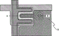
In the reciprocal cross shift thin film transistor (TFT) of the liquid crystal indicator that comprises reciprocal cross shift thin film transistor (TFT), form gate insulating film on gate electrode, form the microcrystalline semiconductor film (also referred to as half amorphous semiconductor film) as the channel formation region territory on gate insulating film, form cushion on microcrystalline semiconductor film, form pair of source zone and drain region on cushion, so that the mode that the part of source region and drain region is exposed forms pair of source electrode and the drain electrode that contacts with source region and drain region.Therefore, source region and drain region have the zone that contacts with source electrode and drain electrode and the zone that with source electrode and drain electrode, does not contact.In addition, in the outside of source electrode and drain electrode, the part of source region and drain region and the part of cushion are exposed, and source electrode and drain electrode are not overlapping with the end of the end of microcrystalline semiconductor film and source region and drain region.In addition, form source region and the end of drain region and the end of cushion in the outside of the end of source electrode and drain electrode.
End by source electrode and drain electrode and the end of source region and drain region are inconsistent, and form the end of source region and drain region in the outside of the end of source electrode and drain electrode, distance between the end of source electrode and drain electrode is elongated, thereby can prevent leakage current and short circuit between source electrode and drain electrode.In addition, electric field is not concentrated in the end of source electrode and drain electrode and source region and drain region, thereby can prevent the leakage current that produces between gate electrode and source electrode and drain electrode.
In addition, the part of cushion has recess, and the side of this recess is consistent with the end of source region and drain region.Due to the part of cushion have between recess and former zone and drain region distance from and therefore distance that charge carrier between source region and drain region moves can reduce the leakage current that produces between source region and drain region.
In addition, be formed with cushion between microcrystalline semiconductor film and source region and drain region.Microcrystalline semiconductor film is as the channel formation region territory.In addition, cushion is used as high resistance area in the oxidation that prevents microcrystalline semiconductor film.Use the amorphous semiconductor film of high resistivity to be formed with cushion between microcrystalline semiconductor film and source region and drain region.Thus, the field effect mobility of thin film transistor (TFT) of the present invention is high, and the leakage current in when cut-off (, when gate electrode is applied negative voltage) is few, and it is high to leak resistance to pressure.
Adopt amorphous semiconductor film as cushion.Moreover, the preferred any above amorphous semiconductor film that comprises nitrogen, hydrogen, halogen that adopts.Comprise any of nitrogen, hydrogen, halogen by amorphous semiconductor film, can reduce the oxidation that is included in the crystal grain in microcrystalline semiconductor film.
Can pass through plasma CVD method, sputtering method etc. and form cushion.In addition, after forming amorphous semiconductor film,, by use the processing of nitrogen plasma, hydrogen plasma or halogen plasma for amorphous semiconductor film, can make amorphous semiconductor film nitrogenize, hydrogenation or halogenation.
Can reduce the oxidation of the crystal grain in being included in microcrystalline semiconductor film by cushion is set on the surface of microcrystalline semiconductor film, therefore can reduce the degeneration of the electrical characteristics of thin film transistor (TFT).
Different from polycrystal semiconductor film, microcrystalline semiconductor film can be formed directly on substrate.Particularly, silane can be formed as unstrpped gas and with plasma CVD equipment.Be also included within amorphous semiconductor the microcrystalline semiconductor film of the crystal grain that contains 0.5nm to 20nm by the microcrystalline semiconductor film of said method manufacturing.Therefore, different from the situation of using polycrystal semiconductor film, need to not carry out the crystallization operation after forming semiconductor film.Can reduce the process number while making thin film transistor (TFT), and can improve the yield rate of liquid crystal indicator and suppress cost.In addition, frequency of utilization is that the plasma of the above microwave of 1GHz has high electron density, thereby easily from the silane of separating unstrpped gas.Therefore, be the plasma CVD method of the microwave more than 1GHz by frequency of utilization, be that tens MHz compare to the microwave plasma CVD technique of hundreds of MHz with frequency, microcrystalline semiconductor film can be easier to make, and film forming speed can be improved.Thereby, can improve the production of liquid crystal indicator.
In addition, use microcrystalline semiconductor film to make thin film transistor (TFT) (TFT), and with this thin film transistor (TFT) be used in pixel section, driving circuit is made liquid crystal indicator.Use the field effect mobility of the thin film transistor (TFT) of microcrystalline semiconductor film to be 1cm
2/ Vsec to 20cm
2/ Vsec, it is amorphous semiconductor film to be used for 2 times to 20 times of thin film transistor (TFT) in channel formation region territory.Therefore part or all of driving circuit can be formed on the substrate identical with pixel section, form system type panel (systemon panel).
In addition, liquid crystal indicator comprises liquid crystal cell.In addition, liquid crystal indicator also comprises the panel that is in the sealed state of liquid crystal cell and is in the IC that will comprise controller etc. and is arranged on the module of the state on this panel.Moreover, the present invention relates to make the component substrate that is equivalent to the mode of liquid crystal cell before completing in the process of this liquid crystal indicator, possess in each of a plurality of pixels of this component substrate voltage is supplied with unit to liquid crystal cell.Component substrate adopts variety of way, both can be in the state of the pixel electrode that only is formed with liquid crystal cell, after can being in again the conducting film that becomes pixel electrode and carry out etching and form pixel electrode state before.
Note, the liquid crystal indicator in this instructions refers to image display device, liquid crystal display device or light source (comprising lighting device).In addition, also all be included in liquid crystal indicator as lower module: the module that connector such as FPC (flexible printing substrate), TAB (belt engages automatically) adhesive tape or TCP (band carries encapsulation) is installed; The front end of TAB adhesive tape and TCP is provided with the module of printed wiring board; Or by COG (brilliant glass tipping, chip on glass) mode, IC (integrated circuit) is directly installed on module in liquid crystal cell.
, according to the present invention, can make the liquid crystal indicator that comprises the thin film transistor (TFT) that electrical characteristics are good and reliability is high in the production highland.
Description of drawings
Figure 1A and 1B are the sectional views of the manufacture method of explanation liquid crystal indicator of the present invention;
Fig. 2 A to 2C is the sectional view of the manufacture method of explanation liquid crystal indicator of the present invention;
Fig. 3 A and 3B are the sectional views of the manufacture method of explanation liquid crystal indicator of the present invention;
Fig. 4 A and 4B are the sectional views of the manufacture method of explanation liquid crystal indicator of the present invention;
Fig. 5 A to 5C is the vertical view of the manufacture method of explanation liquid crystal indicator of the present invention;
Fig. 6 A to 6C is the sectional view of the manufacture method of explanation liquid crystal indicator of the present invention;
Fig. 7 A to 7C is the sectional view of the manufacture method of explanation liquid crystal indicator of the present invention;
Fig. 8 A and 8B are the sectional views of the manufacture method of explanation liquid crystal indicator of the present invention;
Fig. 9 A to 9D is the vertical view of the manufacture method of explanation liquid crystal indicator of the present invention;
Figure 10 is the vertical view of explanation microwave plasma CVD device of the present invention;
Figure 11 A to 11D is the sectional view that explanation can be applicable to multi-stage grey scale mask of the present invention;
Figure 12 A to 12C is the skeleton view of explanation display panels of the present invention;
Figure 13 A to 13C is the skeleton view that the electronic equipment of liquid crystal indicator of the present invention is used in explanation;
Figure 14 is the figure that the electronic equipment of liquid crystal indicator of the present invention is used in explanation;
Figure 15 is the figure of explanation liquid crystal indicator of the present invention;
Figure 16 is the figure of explanation liquid crystal indicator of the present invention;
Figure 17 is the figure of explanation liquid crystal indicator of the present invention;
Figure 18 is the figure of explanation liquid crystal indicator of the present invention;
Figure 19 is the figure of explanation liquid crystal indicator of the present invention;
Figure 20 is the figure of explanation liquid crystal indicator of the present invention;
Figure 21 is the figure of explanation liquid crystal indicator of the present invention;
Figure 22 is the figure of explanation liquid crystal indicator of the present invention;
Figure 23 is the figure of explanation liquid crystal indicator of the present invention;
Figure 24 is the figure of explanation liquid crystal indicator of the present invention;
Figure 25 is the figure of explanation liquid crystal indicator of the present invention;
Figure 26 is the figure of explanation liquid crystal indicator of the present invention;
Figure 27 is the figure of explanation liquid crystal indicator of the present invention;
Figure 28 is the figure of explanation liquid crystal indicator of the present invention;
Figure 29 A and 29B are vertical view and the sectional views of explanation display panels of the present invention;
Figure 30 is the block diagram of the structure of explanation liquid crystal indicator of the present invention;
Figure 31 is the equivalent circuit diagram of structure of the driving circuit of explanation liquid crystal indicator of the present invention;
Figure 32 is the equivalent circuit diagram of structure of the driving circuit of explanation liquid crystal indicator of the present invention;
Figure 33 is the vertical view of layout of the driving circuit of explanation liquid crystal indicator of the present invention;
Figure 34 A and 34B illustrate the figure that detects the result of microcrystalline semiconductor film by Raman spectroscopy;
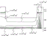
Figure 35 is the illustraton of model for device simulation;
Figure 36 illustrates by carrying out the figure of the current-voltage characteristic that device simulation obtains;
Figure 37 A and 37B are the figure that illustrates by the distribution of electron's density that carries out the thin film transistor (TFT) that device simulation obtains.
Selection figure of the present invention is Fig. 2 A to 2C.
Embodiment
Below, be described with reference to the accompanying drawings about embodiments of the present invention.But, the person of an ordinary skill in the technical field can understand a fact at an easy rate, be exactly that the present invention can be with a plurality of multi-form enforcements, its mode and detailed content can be transformed to various forms and not break away from aim of the present invention and scope thereof.Therefore, the present invention should not be interpreted as only being limited in the content that present embodiment puts down in writing.
In the present embodiment, the manufacturing process for the thin film transistor (TFT) that is used for liquid crystal indicator, describe with reference to Figure 1A to Figure 12 C.Figure 1A to Fig. 4 B, Fig. 6 A to Fig. 8 B are the sectional views that the manufacturing process of thin film transistor (TFT) is shown, and Fig. 5 A to 5C and Fig. 9 A to 9D be one in pixel thin film transistor (TFT) and the vertical view of the join domain of pixel electrode.
N-shaped thin film transistor (TFT) with microcrystalline semiconductor film more preferably is used for driving circuit, because its field effect mobility is higher than the field effect mobility of the p-type thin film transistor (TFT) with microcrystalline semiconductor film.The polarity that preferably makes all thin film transistor (TFT)s that are formed on same substrate is identical, to suppress the increase of process number., at this, with the thin film transistor (TFT) of n channel-type, describe.
As shown in Figure 1A, form gate electrode 51 on substrate 50.Substrate 50 can use such as barium borosilicate glass, aluminium borosilicate glass, alumina silicate glass etc. of alkali-free glass substrate or the ceramic substrate of making by melting method or floating forwarding method (float method), can also use stable on heating plastic with the treatment temperature that can bear this manufacturing process etc.In addition, can also use dielectric film is set on the metal substrate surfaces such as stainless steel alloy substrate.In the situation that substrate 50 is female glass, its size can adopt the first generation (320mm * 400mm), the second generation (400mm * 500mm), the third generation (550mm * 650mm), the 4th generation (680mm * 880mm or 730mm * 920mm), the 5th generation (1000mm * 1200mm or 1100mm * 1250mm), the 6th generation (1500mm * 1800mm), the 7th generation (1900mm * 2200mm), the 8th generation (2160mm * 2460mm), the 9th generation (2400mm * 2800mm or 2450mm * 3050mm), the tenth generation (2950mm * 3400mm) etc.
Use metal material or its alloy material of titanium, molybdenum, chromium, tantalum, tungsten, aluminium etc. to form gate electrode 51.Can form conducting film on substrate 50 by sputtering method, vacuum vapour deposition, by photoetching technique or ink-jet method, form mask on this conducting film, and use this mask etching conducting film, form gate electrode 51.Note,, as being used for improving the compactedness of gate electrode 51 and preventing from being diffused into the barrier metal of substrate, also the nitride film of above-mentioned metal material can be arranged between substrate 50 and gate electrode 51.At this, the Etching mask of using the first photomask to form by employing comes etching to be formed on conducting film on substrate 50, forms gate electrode 51.
Note,, because form dielectric film, semiconductor film and wiring etc. on gate electrode 51,, so its end is preferably processed to conical in shape, in order to prevent, disconnect.In addition, although not shown, can form simultaneously the wiring that is connected to gate electrode by this operation.
Secondly, form in order gate insulating film 52a, 52b, microcrystalline semiconductor film 53, cushion 54, the semiconductor film 55 that is added with the impurity element of giving a conductivity type, conducting film 65a to 65c on gate electrode 51.Then, coating resist 80 on conducting film 65c.Note, preferably form at least continuously gate insulating film 52a, 52b, microcrystalline semiconductor film 53 and cushion 54.Moreover, the preferred semiconductor film 55 that forms gate insulating film 52a, 52b, microcrystalline semiconductor film 53, cushion 54 and be added with the impurity element of giving a conductivity type continuously.By forming at least continuously gate insulating film 52a, 52b, microcrystalline semiconductor film 53 under the state not contacting atmosphere, reaching cushion 54, can form each lamination interface and by Atmospheric components and the pollution impurity element that is suspended in atmosphere, do not polluted, therefore can reduce the inhomogeneous of tft characteristics.
At this, oxygen silicon nitride membrane refers to have the film of following composition: the amount of oxygen is more than the amount of nitrogen, and when adopting rutherford backscattering spectroscopy method (RBS:Rutherford BackscatteringSpectrometry) and hydrogen forward scattering method (HFS:Hydrogen Forward Scattering) to detect, as concentration range, the oxygen that comprises 50 atom % to 70 atom %, the nitrogen that comprises 0.5 atom % to 15 atom %, the silicon that comprises 25 atom % to 35 atom %, comprise the hydrogen of 0.1 atom % to 10 atom %.In addition, silicon oxynitride film refers to have the film of following composition: the content of nitrogen is more than the content of oxygen, and when adopting RBS and HFS to detect, as concentration range, the oxygen that comprises 5 atom % to 30 atom %, the nitrogen that comprises 20 atom % to 55 atom %, comprise the silicon of 25 atom % to 35 atom %, comprises the hydrogen of 10 atom % to 30 atom %.But when the summation of the atom that forms silicon oxynitride or silicon oxynitride was 100 atom %, the ratio that contains of nitrogen, oxygen, silicon and hydrogen was included in above-mentioned scope.
Can be tens MHz by frequency of utilization be that microwave plasma CVD device more than 1GHz forms this microcrystalline semiconductor film to the high-frequency plasma CVD method of hundreds of MHz or frequency.Typically, can use hydrogen dilute Si H
4, Si
2H
6Deng silane form.In addition, except using silane and hydrogen, can also use one or more rare gas elements that are selected from helium, argon, krypton, neon to dilute, form microcrystalline semiconductor film.More than 50 times below 1000 times of the silane that the throughput ratio of hydrogen is set as this moment, be preferably set to more than 50 times below 200 times more preferably 100 times.Note, also can use SiH
2Cl
2, SiHCl
3, SiCl
4, SiF
4Deng the replacement silane.
In addition, due to when schematically not adding the impurity element of controlling for valence electron, microcrystalline semiconductor film presents weak N-shaped electric conductivity, so can, by give the impurity element of p-type for the microcrystalline semiconductor film interpolation in the channel formation region territory as thin film transistor (TFT) when forming film or after forming film, control threshold value., as the typical case of the impurity element of giving p-type, can enumerate boron, preferably with B
2H
6, BF
3Deng foreign gas with the ratio of 1ppm to 1000ppm, preferably the ratio with 1ppm to 100ppm is blended in silane.And the concentration of boron for example is preferably 1 * 10
14Atoms/cm
3To 6 * 10
16Atoms/cm
3.
In addition, the oxygen concentration of microcrystalline semiconductor film is preferably 5 * 10
19cm
-3Below, more preferably 1 * 10
19cm
-3Below, and the concentration of nitrogen and carbon is respectively 3 * 10
18cm
-3Below.Be blended into oxygen in microcrystalline semiconductor film, nitrogen, and the concentration of carbon by reduction, can prevent the N-shaped of microcrystalline semiconductor film.
Microcrystalline semiconductor film 53 is to be thicker than the thickness below 0nm to 200nm, and preferably with the thickness below the above 100nm of 1nm, more preferably the thickness with the above 50nm of 5nm forms.Microcrystalline semiconductor film 53 is as the channel formation region territory of the thin film transistor (TFT) that forms later.Form microcrystalline semiconductor film 53 by the thickness in the scope with below the above 50nm of 5nm, the thin film transistor (TFT) that forms later becomes complete depletion type.In addition because the film forming speed of microcrystalline semiconductor film 53 is slower than amorphous semiconductor film, be amorphous semiconductor film film forming speed 1/10 to 1/100, so by the attenuate film thickness, can boost productivity.Because microcrystalline semiconductor film consists of crystallite, so its resistance ratio amorphous semiconductor film is low.Thus, in the inclination of the rising part of the curve of the thin film transistor (TFT) expression current-voltage characteristic that microcrystalline semiconductor film is used for the channel formation region territory sharply, its response as on-off element is good and can carry out high-speed driving.In addition,, by microcrystalline semiconductor film being used for the channel formation region territory of thin film transistor (TFT), can suppress the threshold variation of thin film transistor (TFT).Therefore, can make inhomogeneous few liquid crystal indicator of electrical characteristics.
In addition, the mobility ratio amorphous semiconductor film of microcrystalline semiconductor film is high.Therefore,, by using thin film transistor (TFT) that its channel formation region territory forms by the microcrystalline semiconductor film switch as liquid crystal cell, can dwindle the area in channel formation region territory, i.e. the area of thin film transistor (TFT).Thus, the shared area reducing of thin film transistor (TFT) in each pixel, can improve the aperture opening ratio of pixel.As a result, can make the high device of resolution.
Can be by using SiH
4, Si
2H
6Deng silane and using plasma CVD method form cushion 54.In addition, can add one or more the rare gas element that is selected from helium, argon, krypton, neon to above-mentioned silane and dilute the formation amorphous semiconductor film.By using its flow to be more than 1 times below 20 times of the flow of silane, be preferably more than 1 times below 10 times, more preferably the hydrogen below 5 times more than 1 times, can form the amorphous semiconductor film that comprises hydrogen.In addition,, by using above-mentioned silane and nitrogen or ammonia, can form the amorphous semiconductor film that comprises nitrogen.In addition, by using above-mentioned silane and the gas (F that comprises fluorine, chlorine, bromine or iodine
2, Cl
2, Br
2, I
2, HF, HCl, HBr, HI etc.), can form the amorphous semiconductor film that comprises fluorine, chlorine, bromine or iodine.Note, can use SiH
2Cl
2, SiHCl
3, SiCl
4, SiF
4Deng.
In addition, as cushion 54, can be with amorphous semiconductor as target and carry out sputter with hydrogen or rare gas and form amorphous semiconductor film.At this moment, by with ammonia, nitrogen or N
2O is included in atmosphere, can form the amorphous semiconductor film that contains nitrogen.In addition, by containing the gas (F of fluorine, chlorine, bromine or iodine
2, Cl
2, Br
2, I
2, HF, HCl, HBr, HI etc.) be included in atmosphere, can form the amorphous semiconductor film that contains fluorine, chlorine, bromine or iodine.
In addition, as cushion 54, also can be on the surface of microcrystalline semiconductor film 53 using plasma CVD method or sputtering method form amorphous semiconductor film, then the surface of amorphous semiconductor film is used the processing of hydrogen plasma, nitrogen plasma or halogen plasma, make amorphous semiconductor film surface hydriding, nitrogenize or halogenation.Perhaps, also can use to the surface of amorphous semiconductor film the processing of helium plasma, neon plasma, argon plasma, krypton plasma etc.
The amorphous semiconductor film that preferred use does not comprise crystal grain forms cushion 54.Therefore,, in the situation that proportion is high frequency plasma cvd method or the microwave plasma CVD technique formation amorphous semiconductor films of tens MHz to hundreds of MHz, preferably control membrance casting condition so that it becomes the amorphous semiconductor film that does not comprise crystal grain.
The part of cushion 54 is etched in the forming process of the source region of back and drain region sometimes, thereby cushion 54 preferably forms with its a part of residual thickness etching after.Typically say, preferably with the thickness below the above 400nm of 150nm, form cushion 54.When thin film transistor (TFT) to apply voltage high (for example, the 15V left and right) in liquid crystal indicator, while making its film thickness form cushion 54 for heavy back as shown in above-mentioned scope, resistance to pressure improves, thereby even thin film transistor (TFT) is applied in high voltage, also can prevent the degeneration of thin film transistor (TFT).
Note, cushion 54 preferably is not added with impurity element such as phosphorus, the boron etc. of giving a conductivity type.Especially, be used for controlling that threshold value is included in the boron in microcrystalline semiconductor film or the phosphorus that is included in the semiconductor film that is added with the impurity element of giving a conductivity type is not preferably sneaked in cushion 54.As a result,, by eliminating the generation zone of the leakage current that PN junction causes, can realize the minimizing of leakage current.In addition, be not added with the impurity element of giving a conductivity type such as the amorphous semiconductor film of phosphorus, boron etc. by forming between the semiconductor film being added with the impurity element of giving a conductivity type and microcrystalline semiconductor film, can prevent from being included in respectively the Impurity Diffusion in microcrystalline semiconductor film and source region and drain region.
By forming amorphous semiconductor film on the surface at microcrystalline semiconductor film 53, further form the amorphous semiconductor film that comprises hydrogen, nitrogen or halogen, can prevent from being included in the autoxidation of the grain surface of microcrystalline semiconductor film 53.Particularly, in amorphous semiconductor and the contacted zone of micrinite, because being subjected to local stress, easily produce crack.Produce the oxidation of crystal grain when this crack contacts with oxygen, and form monox.Yet,, by forming cushion on the surface at microcrystalline semiconductor film 53, can prevent the oxidation of micrinite.In addition,, by forming cushion, can prevent from being blended in microcrystalline semiconductor film when back forms the etch residue that produces when source region and drain region.
In addition, the amorphous semiconductor film that uses amorphous semiconductor film or use to comprise hydrogen, nitrogen or halogen forms cushion 54.Large (energy gap of amorphous semiconductor film is 1.1eV to 1.5eV to the energy gap of amorphous semiconductor film than the energy gap of microcrystalline semiconductor film, and the energy gap of microcrystalline semiconductor film is 1.6eV to 1.8eV), resistance is high, and mobility is low, is 1/5 to 1/10 of microcrystalline semiconductor film.Thus, in the thin film transistor (TFT) that forms in the back, the cushion that is formed between source region and drain region and microcrystalline semiconductor film is used as high resistance area, and microcrystalline semiconductor film is as the channel formation region territory.Therefore, can reduce the cut-off current of thin film transistor (TFT).When this thin film transistor (TFT) is used as the on-off element of liquid crystal indicator, can improve the contrast of liquid crystal indicator.
In the situation that form n channel-type thin film transistor (TFT), add phosphorus as the exemplary impurity element, namely for silane, add PH
3Deng foreign gas, form the semiconductor film 55 that is added with the impurity element of giving a conductivity type, get final product.In addition,, in the situation that form p channel-type thin film transistor (TFT), add boron and get final product as the exemplary impurity element, namely for silane, add B
2H
6Deng foreign gas get final product.Can use microcrystalline semiconductor film or amorphous semiconductor film to form the semiconductor film 55 that is added with the impurity element of giving a conductivity type.Moreover, also can use the lamination of the amorphous semiconductor film that is added with the impurity element of giving a conductivity type and the microcrystalline semiconductor film that is added with the impurity element of giving a conductivity type to form the semiconductor film 55 that is added with the impurity element of giving a conductivity type.By in cushion 54 1 sides, forming the amorphous semiconductor film that is added with the impurity element of giving a conductivity type, and formation thereon is added with the microcrystalline semiconductor film of the impurity element of giving a conductivity type, resistance gradually changes, and, so charge carrier easily flows through, and can improve mobility.Form the semiconductor film 55 that is added with the impurity element of giving a conductivity type with the thickness below the above 50nm of 2nm.Be added with the film thickness of the semiconductor film of the impurity element of giving a conductivity type by attenuate, can boost productivity.
At this, with reference to Figure 10, a kind of plasma CVD equipment is shown, this microwave plasma CVD device can carry out being added with the step of the semiconductor film 55 of the impurity element of giving a conductivity type to formation from the step that forms gate insulating film 52a, 52b continuously.Figure 10 is the schematic diagram of overlooking cross section that plasma CVD equipment is shown, and it has and possess load chamber 1110, relief chamber 1115, reaction chamber (1) 1111 structure to reaction chamber (4) 1114 around common chamber 1120.Possess gate valve 1122 to 1127 between common chamber 1120 and each chamber, interfere with each other in each indoor processing of carrying out preventing.Substrate is loaded in the box 1128,1129 of load chamber 1110, relief chamber 1115, and then the delivery unit 1121 by common chamber 1120 is sent to reaction chamber (1) 1111 to reaction chamber (4) 1114.This microwave plasma CVD device can distribute reaction chamber for each accumulating film kind, thereby can under the state of atmosphere contact not form continuously a plurality of different coverlays.
At reaction chamber (1) to each of reaction chamber (4), stacked formation gate insulating film 52a, 52b, microcrystalline semiconductor film 53, cushion 54 and the semiconductor film 55 that is added with the impurity element of giving a conductivity type respectively.In the case, by conversion unstrpped gas, stacked a plurality of different types of film continuously.In the case, form gate insulating film, then the silane of silane etc. is incorporated in reaction chamber, make residual oxygen and silane reaction, and reactant is discharged to the outside of reaction chamber, thereby can reduce residual oxygen concentration in reaction chamber.As a result, can reduce the oxygen concentration that is included in microcrystalline semiconductor film.In addition, can prevent from being included in the oxidation of the crystal grain in microcrystalline semiconductor film.
Perhaps, form gate insulating film 52a, 52b, microcrystalline semiconductor film 53 and cushion 54 in reaction chamber (1) and reaction chamber (3), and form the semiconductor film 55 that is added with the impurity element of giving a conductivity type in reaction chamber (2) and reaction chamber (4).By only using the impurity of giving a conductivity type to carry out individually film forming, the impurity element of giving a conductivity type that can prevent from remaining in reaction chamber is blended in other films.
Like this,, due to the semiconductor film 55 that can use the microwave plasma CVD device that is connected with a plurality of reaction chambers to form simultaneously gate insulating film 52a, 52b, microcrystalline semiconductor film 53, cushion 54 and be added with the impurity element of giving a conductivity type, therefore improve production.In addition,, even safeguard and clean, also can form film in other reaction chambers in certain reaction chamber, thereby can shorten film forming period (cycle time).In addition, because can form each lamination interface under the state that the pollution impurity element by Atmospheric components and in being suspended in atmosphere not pollutes, so can reduce characteristic inhomogeneous of thin film transistor (TFT).
In addition, can form gate insulating film 52a, 52b in reaction chamber (1), can form microcrystalline semiconductor film 53 and cushion 54 in reaction chamber (2), can form the semiconductor film 55 that is added with the impurity element of giving a conductivity type in reaction chamber (3).in addition, using silicon oxide film or oxygen silicon nitride membrane to form gate insulating film 52a, and use silicon nitride film or silicon oxynitride film to form in the situation of gate insulating film 52b, five reaction chambers also can be set, and form silicon oxide film or the oxygen silicon nitride membrane of gate insulating film 52a in reaction chamber (1), form silicon nitride film or the silicon oxynitride film of gate insulating film 52b in reaction chamber (2), form microcrystalline semiconductor film in reaction chamber (3), form cushion in reaction chamber (4), form the semiconductor film that is added with the impurity element of giving a conductivity type in reaction chamber (5).In addition, because the film forming speed of microcrystalline semiconductor film is slower, so also can form microcrystalline semiconductor film in a plurality of reaction chambers.For example, also can form gate insulating film 52a, 52b in reaction chamber (1), form microcrystalline semiconductor film 53 in reaction chamber (2) and (3), form cushion 54 in reaction chamber (4), form the semiconductor film 55 that is added with the impurity element of giving a conductivity type in reaction chamber (5).Like this,, by form simultaneously microcrystalline semiconductor film 53 in a plurality of reaction chambers, can boost productivity.Note, the film of the kind that at this moment preferred use will form applies the inwall of each reaction chamber.
Due to when using the plasma CVD equipment of this structure, can form film or a kind of film of similar kind in each reaction chamber, and form continuously above-mentioned film under the state that is not exposed to atmosphere, therefore can form each lamination interface not by the residue of established film and under the state of the pollution of the impurity element in being suspended in atmosphere.
Note,, although be respectively arranged with load chamber and the chamber of removing stage makeup and costume in plasma CVD equipment shown in Figure 10, also can arrange one and load/remove stage makeup and costume chamber.In addition, also spare room can be set in the microwave plasma CVD device., owing to can shorten to by in spare room, substrate being carried out preheating the heat time heating time that forms film in each reaction chamber, therefore can boost productivity.
Below, the film forming processing is described.In this film forming is processed, select the gas of supplying with from gas supply part according to its purpose, get final product.
, at this, as one, exemplify out following method: form oxygen silicon nitride membrane as gate insulating film 52a, and form silicon oxynitride film as gate insulating film 52b.
At first, clean for the inner fluoro free radical that uses of the container handling of the reaction chamber of microwave plasma CVD device.Note,, by fluorocarbons, nitrogen fluoride or fluorine being incorporated in the plasma generator that is arranged on the reaction chamber outside and from solution, then fluoro free radical is incorporated in reaction chamber, can clean reaction chamber.
By after the use fluoro free radical cleans, a large amount of hydrogen is incorporated in reaction chamber, residual fluorine and hydrogen in reaction chamber are reacted each other, thereby can reduce the concentration of residual fluorine.Thus, can reduce the fluorine mixed volume of the diaphragm that forms at reaction chamber wall for back, and thickness that can the attenuate diaphragm.
Then, pile up oxynitride film as diaphragm on the surface of the inwall of the container handling of reaction chamber.At this, the pressure in container handling is 1Pa to 200Pa, is preferably 1Pa to 100Pa, and any above gas of rare gas of introducing helium, argon, xenon, krypton etc. is as plasma ignition gas.Moreover, any and hydrogen of introducing rare gas.Particularly, preferably use helium as plasma ignition gas, more preferably use helium and hydrogen as plasma ignition gas.
The ionization energy of helium is higher, is 24.5eV.But,, because quasi-stationary state is positioned at about 20eV, therefore can carry out ionization with about 4eV in discharge.Thus, discharge ionization voltage is low, and easy sustain discharge.Thereby can keep equably plasma and realize energy-conservation.
In addition, also can introduce any above and carrier of oxygen of the rare gas that uses helium, argon, xenon, krypton etc. as plasma ignition gas., by carrier of oxygen is incorporated in container handling together with rare gas, can easily carry out lighting of plasma.
Then, make the power turn-on of supply unit, and at supply unit, be output as 500W to 6000W, be preferably in the situation of 4000W to 6000W and produce plasma.Then, unstrpped gas is incorporated in container handling from gas supply department.Particularly,, by introducing nitrous oxide, rare gas, reaching silane as unstrpped gas, form oxygen silicon nitride membrane as diaphragm on the inner wall surface of container handling.The flow of the silane of this moment is 50sccm to 300sccm, and the flow of nitrous oxide is 500sccm to 6000sccm, and the film thickness of diaphragm is 500nm to 2000nm.
Then, stopping the supply of unstrpped gas, reducing the pressure in container handling, and after making the power supply cut-off of supply unit, substrate is being arranged on trestle table in container handling.
Then,, by the operation identical with said protection film, pile up oxygen silicon nitride membrane as gate insulating film 52a on substrate.
After the oxygen silicon nitride membrane of piling up predetermined thickness, stop the supply of unstrpped gas, reduce the pressure in container handling, and make the power-off of supply unit.
Then, the pressure in container handling is 1Pa to 200Pa, is preferably 1Pa to 100Pa, as plasma ignition gas, introduce helium, argon, xenon, krypton etc. rare gas any above, unstrpped gas silane, nitrous oxide, reach ammonia.Note,, as unstrpped gas, also can introduce nitrogen and replace ammonia.Then, make the electric power starting of supply unit, and at supply unit, be output as 500W to 6000W, be preferably in the situation of 4000W to 6000W and produce plasma.Then, unstrpped gas is incorporated in container handling from gas supply department, forms silicon oxynitride film as gate insulating film 52b on the oxygen silicon nitride membrane of substrate 1130.Then, stop the supply of unstrpped gas, reduce the pressure in container handling, and make the power-off of supply unit, finish film forming procedure.
According to above-mentioned steps, form continuously oxygen silicon nitride membrane and silicon oxynitride film by the diaphragm take reaction chamber wall as oxygen silicon nitride membrane and on substrate, the impurity that can reduce monox etc. is blended in the silicon oxynitride film of upper strata one side.By adopting the supply unit can produce microwave to form above-mentioned film as the microwave plasma CVD technique of supply unit, plasma density improves and can form the film of high resistance to pressure.When this film is used as gate insulating film, can reduce the inhomogeneous of transistorized threshold value.In addition, can improve the BT characteristic.In addition, for the patience of static, improve, thereby even can make, be applied in high voltage and also be not easy the transistor that destroys.And, can also make and destroy in time few transistor and the few transistor of hot carrier damage.
In addition, in the situation that the individual layer that will use the oxygen silicon nitride membrane that the microwave plasma CVD device forms adopts the formation method of said protection film and the formation method of oxygen silicon nitride membrane as gate insulating film.Particularly,, by being set as for the throughput ratio of the nitrous oxide of silane more than 50 times below 300 times, be preferably set to more than 50 times below 250 times, can form the oxygen silicon nitride membrane of high resistance to pressure.
Then, a kind of one-tenth membrane processing method is shown, wherein by plasma CVD method, forms continuously microcrystalline semiconductor film and reach the amorphous semiconductor film that is used as cushion.At first, similarly carry out the cleaning of reaction chamber with above-mentioned gate insulating film.Then, pile up silicon fiml as diaphragm in container handling.At this, the pressure in container handling is 1Pa to 200Pa, is preferably 1Pa to 100Pa, and any above gas of rare gas of introducing helium, argon, xenon, krypton etc. is as plasma ignition gas.In addition, also can introduce hydrogen together with rare gas.
Then, make the electric power starting of supply unit, and at supply unit, be output as 500W to 6000W, be preferably in the situation of 4000W to 6000W and produce plasma.Then, unstrpped gas is incorporated in container handling from gas supply department.Particularly,, by introducing silane gas, reaching hydrogen as unstrpped gas, form microcrystalline sillicon film as diaphragm on the inner wall surface of container handling.In addition, can add one or more rare gas elements that are selected from helium, argon, krypton, neon to silane gas and hydrogen and dilute to form microcrystalline semiconductor film.The throughput ratio of the hydrogen for silane of this moment is more than 5 times below 1000 times, is preferably more than 50 times below 200 times, more preferably more than 100 times below 150 times.In addition, the film thickness of the diaphragm of this moment is 500nm to 2000nm.Note, also can before making the electric power starting of supply unit, can also introduce silane gas and hydrogen except above-mentioned rare gas in container handling.
In addition, can form amorphous semiconductor film as diaphragm with silane gas and hydrogen that utilization is selected from one or more rare gas elementary dilutions in helium, argon, krypton, neon.
Then, stopping the supply of unstrpped gas, reducing the pressure in container handling, and after making the power-off of supply unit, substrate is being arranged on trestle table in container handling.
Then, also can carry out hydrogen plasma for the surface that is formed on the gate insulating film 52b on substrate processes.Process by carried out hydrogen plasma before forming microcrystalline semiconductor film, can reduce the lattice strain on the interface of gate insulating film and microcrystalline semiconductor film, and can improve the interfacial characteristics of gate insulating film and microcrystalline semiconductor film.Therefore, can improve the electrical characteristics of the thin film transistor (TFT) that forms later.
In addition; in above-mentioned hydrogen plasma is processed; process by also the amorphous semiconductor film that is formed on the diaphragm in container handling or microcrystalline semiconductor film being carried out hydrogen plasma, diaphragm is etched and pile up a small amount of semiconductor is arranged on the surface of gate insulating film 52b.This semiconductor becomes the core of crystalline growth, because this core microcrystalline semiconductor film is piled up.As a result, the lattice strain at the interface of gate insulating film and microcrystalline semiconductor film can be reduced, and the interfacial characteristics of gate insulating film and microcrystalline semiconductor film can be improved.Thus, can improve the electrical characteristics of the thin film transistor (TFT) that forms later.
Then,, by the operation identical with said protection film, pile up microcrystalline sillicon film on substrate.The film thickness of microcrystalline sillicon film, for being thicker than below 0nm to 50nm, preferably is thicker than below 0nm to 20nm.
After the microcrystalline sillicon film of piling up predetermined thickness, stop the supply of unstrpped gas, reduce the pressure in container handling, and make the power supply cut-off of supply unit, finish to form the process of microcrystalline semiconductor film.
Then, reduce the pressure in container handling and regulate the flow of unstrpped gas.Particularly, the membrance casting condition of the throughput ratio microcrystalline semiconductor film of hydrogen is reduced significantly.Typically, the flow of the hydrogen that introduce is more than 1 times below 20 times of flow of silane, is preferably more than 1 times below 10 times, more preferably more than 1 times below 5 times.Perhaps, hydrogen be not incorporated in container handling and introduce silane gas.Like this,, by reducing the flow for the hydrogen of silane, can improve the film forming speed as the amorphous semiconductor film of cushion.Perhaps, also use one or more rare gas elements that are selected from helium, argon, krypton, neon to dilute except silane gas.Then, the electric power starting by making supply unit also is set as 500W to 6000W with its output, is preferably 4000W to 6000W and produces plasma, thereby can form amorphous semiconductor film.Because the film forming speed of amorphous semiconductor film is higher than the film forming speed of microcrystalline semiconductor film, therefore can must be low with the pressure setting in container handling.The film thickness of the amorphous semiconductor film of this moment is 200nm to 400nm.
After the amorphous semiconductor film of piling up predetermined thickness, stop the supply of unstrpped gas, reduce the pressure in container handling, and make the power-off of supply unit, finish to form the process of amorphous semiconductor film.
Note, also can light under the state of plasma the amorphous semiconductor film that forms microcrystalline semiconductor film 53 and be used as cushion 54.Particularly, reduce gradually for the throughput ratio of the hydrogen of the silane of the unstrpped gas that is used for forming microcrystalline semiconductor film 53 and stacked microcrystalline semiconductor film 53 and as the amorphous semiconductor film of cushion 54., by said method, impurity is deposited on the interface of microcrystalline semiconductor film 54 and cushion 54 and forms the interface that should tail off, and can improve the electrical characteristics of the thin film transistor (TFT) that forms later.
In the situation that form microcrystalline semiconductor film 53, preferred frequency of utilization is the above microwave plasma CVD device of 1GHz.Because the electron density of microwave plasma is high, and from unstrpped gas, form a plurality of free radicals and supply with to substrate 1130, therefore promoting the free radical surface reaction on substrate, can improve the film forming speed of microcrystal silicon.Can use the high frequency of 1MHz to 20MHz, the high frequency that is typically 13.56MHz or greater than the VHF about 20MHz to 120MHz, is with, the plasma CVD method that is typically 27.12MHz, 60MHz forms microcrystalline semiconductor film.
Note, in each manufacturing process of gate insulating film and semiconductor film, when being formed with the diaphragm of 500nm to 2000nm on the inwall at reaction chamber, can omitting above-mentioned cleaning treatment and diaphragm and form processing.
Then, form conducting film 65a to 65c on the semiconductor film 55 that is added with the impurity element of giving a conductivity type.Preferred use aluminium, copper or be added with, the thermotolerances such as silicon, titanium, neodymium, scandium, molybdenum improve element or hillock prevents that individual layer or the lamination of the aluminium alloy of element from forming conducting film 65a to 65c.In addition, also can adopt following rhythmo structure: use the nitride formation of titanium, tantalum, molybdenum, tungsten or above-mentioned element to contact the film of a side with the semiconductor film that is added with the impurity element of giving a conductivity type, form aluminum or aluminum alloy thereon.Moreover, can also adopt following rhythmo structure: below top the reaching of the nitride folder aluminum or aluminum alloy of use titanium, tantalum, molybdenum, tungsten or above-mentioned element.At this, conducting film with three layers the structure that is laminated with conducting film 65a to 65c is shown as conducting film, the lamination conducting film that the molybdenum film is used as conducting film 65a, 65c as conducting film 65a, 65c and with the aluminium film as the lamination conducting film of conducting film 65b and with titanium film and the aluminium film is used as conducting film 65b for example is shown.Form conducting film 65a to 65c by sputtering method or vacuum vapour deposition.
Can use eurymeric resist or negative resist as resist 80.Illustrate with the eurymeric resist at this.
Then, make resist 80 exposures with multi-stage grey scale mask 59 as the second photomask and to resist 80 irradiation light.
At this, the exposure of multi-stage grey scale mask 59 is used in explanation with reference to Figure 11 A to 11D.
The multi-stage grey scale mask is the mask that can expose with the exposure standard of three kinds for exposed portion, intermediate exposures part and unexposed portion, and exposure that can be by once and the developing procedure Etching mask that forms the zone with multiple (being typically two kinds) thickness.Therefore, by using multi-stage grey scale mask, the quantity that can reduce photomask.
, as the exemplary of multi-stage grey scale mask, has the half-tone mask 59b shown in tone of gray mask 59a, Figure 11 C shown in Figure 11 A.
As shown in Figure 11 A, tone of gray mask 59a consists of the substrate 163 with light transmission, the light shielding part 164 and the diffraction grating 165 that form thereon.In light shielding part 164, the transit dose of light is 0%.On the other hand, diffraction grating 165 becomes the transit dose that can control light for the interval below the resolution limit of the light that exposes by the interval with light transmissive portions such as the line of rabbet joint, point, mesh.Note the line of rabbet joint, point, mesh or the acyclic line of rabbet joint, point, mesh that diffraction grating 165 can periodic.
In the situation that to tone of gray mask 59a irradiation exposure light, as shown in Figure 11 b, the light transmission amount 166 in light shielding part 164 is 0%, and the light transmission amount 166 that is not provided with in the zone of light shielding part 164 and diffraction grating 165 is 100%.In addition, in diffraction grating 165, can regulate light transmission amount 166 in 10% to 70% scope.Interval or the spacing of the line of rabbet joint, point or mesh by regulating diffraction grating 165, can regulate the light transmission amount in diffraction grating 165.
As shown in Figure 11 C, half-tone mask 59b by the substrate 163 with light transmission and form thereon half see through section 167 and light shielding part 168 forms.Half sees through section 167 can use MoSiN, MoSi, MoSiO, MoSiON, CrSi etc.Light shielding part 168 can use the light absorbing light screening material of chromium, chromium oxide etc. to form.
In the situation that to half-tone mask 59b irradiation exposure light, as shown in Figure 11 D, the light transmission amount 169 in light shielding part 168 is 0%, and be not provided with light shielding part 168 and half, through the light transmission amount 169 in the zone of section 167, is 100%.In addition, in half sees through section 167, can regulate light transmission amount 169 in 10% to 70% scope., by regulating half material through section 167, can regulate the half light transmission amount that sees through in section 167.
After using the multi-stage grey scale mask exposure,, by developing, can form as shown in Figure 1B the Etching mask 81 with the different zone of film thickness like that.
Then, by using Etching mask 81, etching microcrystalline semiconductor film 53, cushion 54, the semiconductor film 55 that is added with the impurity element of giving a conductivity type and conducting film 65a to 65c separate.As a result, can form such as shown in Figure 2 A microcrystalline semiconductor film 61, cushion 62, the semiconductor film 63 that is added with the impurity element of giving a conductivity type and conducting film 85a to 85c.Note, Fig. 2 A is equivalent to along the sectional view of the A-B line of Fig. 5 A (but except Etching mask 86).
End sides by microcrystalline semiconductor film 61, cushion 62 tilts, and can prevent from being formed on the leakage current that produces between source region on cushion 62 and drain region and microcrystalline semiconductor film 61.In addition, can also prevent the leakage current that produces between source electrode and drain electrode and microcrystalline semiconductor film 61.The angle of inclination of the end sides of microcrystalline semiconductor film 61 and cushion 62 is 30 ° to 90 °, is preferably 45 ° to 80 °., by with this angle, forming, can prevent the disconnection of step-like caused source electrode or drain electrode.
Then, Etching mask 81 being carried out ashing processes.As a result, the area reducing of resist, and reduced thickness.At this moment, the resist in the zone of thin film thickness (zone overlapping with the part of gate electrode 51) is removed, and can form as shown in Figure 6B separated Etching mask 86 like that.
Then, use Etching mask 86 etchings to be added with semiconductor film 63 and the conducting film 85a to 85c of the impurity element of giving a conductivity type and they are separated., at this, by dry ecthing, separate conducting film 85a to 85c.As a result, can form pair of conductive film 89a to 89c and pair of source zone and drain region 89 as shown in Fig. 2 B.Note, in this etching work procedure, go back the part of etch buffer layers 62.Its a part of etched cushion is depicted as cushion 88.Can form by the operation identical with forming source region and drain region the recess of cushion.At this because the part of cushion 88 by its area reducing Etching mask 86 etchings, so cushion 88 is given prominence to the outside at conductive layer 85a to 85c.
Then, as shown in Figure 2 C, the part of etching conducting film 89a to 89c forms source electrode and drain electrode 92a to 92c.At this, when using 86 pairs of conducting film 89a to 89c wet etchings of Etching mask, the end of conducting film 89a to 89c is optionally etched.As a result, can form the little source electrode of its Area Ratio Etching mask 86 and conducting film 89a to 89c and drain electrode 92a to 92c.The end of the end of source electrode and drain electrode 92a to 92c and source region and drain region 89 is inconsistent and depart from, and namely in the outside of the end of source electrode and drain electrode 92a to 92c, forms the end of source region and drain region 89.Then, remove Etching mask 86.
Note, Fig. 2 C is equivalent to along the sectional view of the A-B line of Fig. 5 B.Be positioned at the outside of the end of source electrode and drain electrode 92c with regard to the end of knowing source region and drain region 89 with reference to Fig. 5 B.The end of cushion 88 is positioned at the outside of the end of source electrode and drain electrode 92c and source region and drain region 89 in addition.In addition, a side of source electrode and drain electrode has partly around the opposing party's of source region and drain region shape (particularly, U font, C font).Thus, can increase area and the magnitude of current in the zone that charge carrier moves, can dwindle the area of thin film transistor (TFT).In addition, because at inboard overlapping microcrystalline semiconductor film and source electrode and the drain electrode 92c of gate electrode 87, so the concavo-convex impact that produces in the end of gate electrode is few.Thereby can suppress the reduction of coverage rate and the generation of leakage current.Note, a side of source electrode and drain electrode also plays the effect of source wiring or leak routing.
As shown in Figure 2 C, because the end of the end by with source electrode and drain electrode 92a to 92c and source region and drain region 89 forms inconsistent departing from, make source electrode and drain electrode 92a to 92c end distance from, therefore can prevent leakage current and short circuit between source electrode and drain electrode.Thus, thin film transistor (TFT) that can fabrication reliability is high and resistance to pressure is high.
, by above-mentioned operation, can form channel-etch type thin film transistor (TFT) 83.In addition, can use two photomasks to form thin film transistor (TFT).
In the thin film transistor (TFT) shown in present embodiment, be laminated with gate insulating film, microcrystalline semiconductor film, cushion, source region and drain region, source electrode and drain electrode on gate electrode, and cushion covers the surface as the microcrystalline semiconductor film in channel formation region territory.In addition, be formed with recess (groove) in the part of cushion, the zone beyond this recess is covered by source region and drain region.In other words,, because the distance that the charge carrier between source region and drain region moves is elongated because of the recess that is formed on cushion, therefore can reduce the leakage current between source region and drain region.In addition, because by the part of etch buffer layers, form recess, so can remove the etch residue that produces in the formation operation of source region and drain region.Thereby can avoid producing leakage current (parasitic channel) between residue in source region and drain region.
In addition, be formed with cushion between the microcrystalline semiconductor film as the channel formation region territory and source region and drain region.In addition, the surface of microcrystalline semiconductor film is cushioned layer covering.Because the cushion that uses high-resistance amorphous semiconductor film to form extends between microcrystalline semiconductor film and source region and drain region, can reduce in the lower leakage current that produces of the situation (that is, gate electrode being applied the situation of negative voltage) of thin film transistor (TFT) cut-off and the degeneration that occurs by applying high voltage.In addition, because be formed with on the surface of microcrystalline semiconductor film by hydrogen and terminate surperficial amorphous semiconductor film as cushion, so can prevent the oxidation of microcrystalline semiconductor film, and during the etch residue that can produce in the formation operation of source region and drain region is blended into microcrystalline semiconductor film.Thus, become electrical characteristics high and leak the good thin film transistor (TFT) of resistance to pressure.
In addition, the end by the end with source electrode and drain electrode and source region and drain region forms inconsistent departing from, make source electrode and drain electrode end distance from, thereby can prevent leakage current and short circuit between source electrode and drain electrode.
Then, as shown in Figure 3A, form dielectric film 76 on source electrode and drain electrode 92a to 92c, source region and drain region 89, cushion 88, microcrystalline semiconductor film 87 and gate insulating film 52b.Dielectric film 76 can similarly form with gate insulating film 52a, 52b.Note, dielectric film 76 is used for preventing from being suspended in the intrusion of the pollution impurity of organism in atmosphere and metal object, water vapor etc., is preferably fine and close film.In addition, by silicon nitride film is used as dielectric film 76, the oxygen concentration in cushion 88 can be 5 * 10
19Atoms/cm
3Below, and be preferably 1 * 10
19Atoms/cm
3Below.
Then, form contact hole in dielectric film 76, then form the pixel electrode 77 that contacts with source electrode or drain electrode 92c in this contact hole.Note, Fig. 3 B is equivalent to along the sectional view of the A-B line of Fig. 5 C.
As pixel electrode 77, can use conductive material such as the indium oxide that comprises tungsten oxide with light transmission, the indium zinc oxide that comprises tungsten oxide, the indium oxide that comprises titanium dioxide, the tin indium oxide that comprises titanium dioxide, tin indium oxide (below, be called ITO), indium zinc oxide, be added with the tin indium oxide of monox etc.
In addition, can use the conductive composition that comprises conducting polymer (also referred to as conductive polymer) to form pixel electrode 77.Preferably have following condition at the pixel electrode that uses conductive composition to form: sheet resistance is that 10000 Ω/below, the transmittance when wavelength is 550nm is more than 70%.In addition, the resistivity that is included in the conducting polymer in conductive composition is preferably below 0.1 Ω cm.
, as conducting polymer, can use so-called pi-electron conjugate class conducting polymer.For example, can enumerate polyaniline or derivatives thereof, polypyrrole or derivatives thereof, polythiophene or derivatives thereof or by two or more interpolymers that form in above-mentioned substance etc.
, by above-mentioned steps, can form the component substrate that can be used in liquid crystal indicator.
Note, as shown in Figure 2 A, after forming microcrystalline semiconductor film 61, cushion 62, being added with the semiconductor film 63 and conducting film 85a to 85c of the impurity element of giving a conductivity type, as shown in Fig. 4 A, use Etching mask 86 etching conducting film 85a to 85c.At this, by with Etching mask 86 and adopt wet etching to carry out isotropically etching, near the exposed division of conducting film 85a to 85c and optionally etched.As a result, can form the little source electrode of its area and Etching mask 86 and drain electrode 92a to 92c.
Then, as shown in Figure 4 B, use Etching mask 86 etchings to be added with the semiconductor film 63 of the impurity element of giving a conductivity type.At this, by with dry ecthing anisotropically etching be added with the semiconductor film 63 of the impurity element of giving a conductivity type, can form the roughly the same source region of its area and Etching mask 86 and drain region 89.
Because the end of the end by with source electrode and drain electrode 92a to 92c and source region and drain region 89 forms inconsistent departing from, make source electrode and drain electrode 92a to 92c end distance from, therefore can prevent leakage current and short circuit between source electrode and drain electrode.Thus, thin film transistor (TFT) that can fabrication reliability is high and resistance to pressure is high.
Shown in Figure 1A to Fig. 4 B,, by adopting wet etching conducting film is carried out etching and adopt dry ecthing to carry out etching to the semiconductor film that is added with the impurity element of giving a conductivity type, can constitute the end of the end of source electrode and drain electrode and source region and drain region inconsistent and different with a small amount of photomask.
Then,, for the manufacture method of the thin film transistor (TFT) different from aforesaid way, with reference to Fig. 6 A to Fig. 9 D, describe.At this, the mutually different structure of source electrode or drain electrode and source wiring or leak routing is shown below.
As shown in Figure 6A, form gate electrode 51 on substrate 50.Secondly, form in order gate insulating film 52a, 52b, microcrystalline semiconductor film 53, cushion 54, the semiconductor film 55 that is added with the impurity element of giving a conductivity type and conducting film 65a on gate electrode 51.Then, apply resist on conducting film 65a, use the multi-stage grey scale mask shown in Figure 1A to form the Etching mask 81 with the different zone of thickness.
Then, use Etching mask 81 etching microcrystalline semiconductor films 53, cushion 54, the semiconductor film 55 that is added with the impurity element of giving a conductivity type and conducting film 65a to separate.As a result, can form such as shown in Figure 6B microcrystalline semiconductor film 61, cushion 62, the semiconductor film 63 that is added with the impurity element of giving a conductivity type and conducting film 85a.Note, Fig. 6 B is equivalent to along the sectional view of the A-B line of Fig. 9 A (still, except Etching mask 86).
Then, form by Etching mask 81 being carried out ashing the Etching mask 86 that has separated.Then, use Etching mask 86 etchings to be added with the semiconductor film 63 of the impurity element of giving a conductivity type and conducting film 85a so that their separate.As a result, can form as shown in Figure 6 C such pair of conductive film 89a and pair of source zone and drain region 88.Note, in this etching work procedure, the part of cushion 62 is also etched.Its a part of etched cushion is expressed as cushion 88.At this because the part of cushion 88 by its area reducing Etching mask 86 etchings, so cushion 88 is given prominence to the outside at conductive layer 89a.Due to as shown in present embodiment, the side of cushion becomes stairstepping, so the coverage rate of the dielectric film that forms later improves.Thus, can reduce thin film transistor (TFT) and be formed on the leakage current that produces between pixel electrode on dielectric film.
Then, Etching mask 86 is carried out ashing.As a result, as shown in Figure 7 A, the area reducing of Etching mask, and its thickness attenuation.Then, the part of the Etching mask 91 etching conducting film 89a that are ashed by use forms source electrode and drain electrode 92a as shown in Figure 7 B like that.The end of the end of source electrode and drain electrode 92a and source region and drain region 89 is inconsistent and depart from.At this, with Etching mask 91 and adopt dry ecthing to carry out the anisotropically exposed division of etching conducting film 89a.Afterwards, remove Etching mask 91.
As a result, form source electrode and the drain electrode 92a less than the area of conducting film 89a.Then, remove Etching mask 91.Note, Fig. 7 B is equivalent to along the sectional view of the A-B line of Fig. 9 B.Be positioned at the outside of the end of source electrode and drain electrode 92a with regard to the end of knowing source region and drain region 89 with reference to Fig. 9 B.In addition, the end of cushion 88 is positioned at the outside of source electrode and drain electrode 92a and source region and drain region 89.In addition, source electrode and drain electrode 92a are separated respectively, not with the electrode contact that is formed in adjacent pixel.Note, although use the Etching mask 91 that 86 ashing form to Etching mask to form source electrode and drain electrode 92a at this,, as shown in Figure 1A to Fig. 4 B, also can use Etching mask 86 to carry out wet etching and form source electrode and drain electrode 92a to 92c.
As shown in Figure 7 B, end by the end with source electrode and drain electrode 92a and source region and drain region 89 forms inconsistent departing from, make source electrode and drain electrode 92a end distance from, thereby can prevent leakage current and short circuit between source electrode and drain electrode.Thus, thin film transistor (TFT) that can fabrication reliability is high and resistance to pressure is high.
Then, shown in Fig. 7 C, form dielectric film 76 on source electrode and drain electrode 92a, source region and drain region 89, cushion 88 and gate insulating film 52b.Can similarly form dielectric film 76 with gate insulating film 52a, 52b.
Then, shown in Fig. 8 A, form contact hole in dielectric film 76, and be formed in this contact hole and contact with the side of source electrode and drain electrode 92a and stacked wiring 93b, 93c.Note, Fig. 8 A is equivalent to along the sectional view of the A-B line of Fig. 9 C.In addition, wiring 93a, 93c is the wiring that the source electrode that is formed in adjacent pixel or drain electrode are connected.
Then, as shown in Figure 8 B, be formed on the pixel electrode 77 that contacts with the opposing party of source electrode and drain electrode 92a in contact hole.Note, Fig. 8 B is equivalent to along the sectional view of the A-B line of Fig. 9 D.
, by above-mentioned operation, can form channel-etch type thin film transistor (TFT) 84.The manufacturing process of channel-etch type thin film transistor (TFT) is few, thereby can reduced cost.In addition, by using the microcrystalline semiconductor film constituting channel, form zone, can obtain 1cm
2/ Vsec to 20cm
2The mobility of/Vsec.Therefore, this thin film transistor (TFT) can be used as the on-off element of the pixel of pixel section, can also be as the element of the driving circuit that forms sweep trace (gate line) side.
, according to present embodiment, can make the high thin film transistor (TFT) of reliability of electrical characteristics.
In the present embodiment, the liquid crystal indicator that comprises the thin film transistor (TFT) shown in embodiment 1 below is shown.
At first, VA (vertical orientation) type liquid crystal indicator is shown.VA type liquid crystal indicator is mode a kind of of arrangement who controls the liquid crystal molecule of liquid crystal panel.VA type liquid crystal indicator be when not being applied in voltage liquid crystal molecule towards the mode for the vertical direction of panel surface.In the present embodiment, especially managing pixel segmentation is several zones (sub-pixs), and molecule was fallen to different directions.Said method is called multidomain (multi-domain) change or multidomain design.In the following description, the liquid crystal indicator of considering the multidomain design is described.
Figure 16 and Figure 17 illustrate respectively pixel electrode and comparative electrode.Note, Figure 16 is the planimetric map that is formed with substrate one side of pixel electrode, and Figure 15 illustrates corresponding to the cross section structure along the A-B line in Figure 14.In addition, Figure 17 is the planimetric map that is formed with substrate one side of comparative electrode.In the following description, describe with reference to above-mentioned accompanying drawing.
The substrate 600 that Figure 15 illustrates the stacked TFT628 of being formed with, connected pixel electrode 624 and keeps capacitance part 630 and the relative substrate 601 that is formed with comparative electrode 640 etc. also are injected with the state of liquid crystal.
Be formed with photomask 632, the first coloring film 634, the second coloring film 636, the 3rd coloring film 638, comparative electrode 640 on the position that spacer 642 in relative substrate 601 forms., by this structure, make to control the height of the projection 644 of orientation of liquid crystal and spacer 642 for different.Form alignment films 648 on pixel electrode 624, form similarly alignment films 646 on comparative electrode 640.Be formed with liquid crystal layer 650 therebetween.
, at this, use column spacer that spacer 642 is shown, but also can scatter the pearl spacer.Moreover, also can form spacer 642 on the pixel electrode 624 that is formed on substrate 600.
Form TFT628, connected pixel electrode 624 and keep capacitance part 630 on substrate 600.Pixel electrode 624 is connected to wiring 618 in contact hole 623, this contact hole 623 connects the dielectric film 620 that covers TFT628, wiring and maintenance capacitance part 630 and the dielectric film 622 that covers dielectric film 620.Can suitably use the thin film transistor (TFT) shown in embodiment 1 as TFT628.In addition, keep capacitance part 630 to be formed by the first capacitance wiring 604, gate insulating film 606 and the second capacitance wiring 617, this first capacitance wiring 604 similarly forms with the grid wiring 602 of TFT628, and this second capacitance wiring 617 similarly forms with wiring 616,618.
, by overlaid pixel electrode 624, liquid crystal layer 650 and comparative electrode 640, form liquid crystal cell.
Figure 16 illustrates the structure on substrate 600.Use the material shown in embodiment 1 to form pixel electrode 624.The line of rabbet joint 625 is set in pixel electrode 624.The line of rabbet joint 625 is used for controlling the orientation of liquid crystal.
TFT629 shown in Figure 16 and connected pixel electrode 626 and maintenance capacitance part 631 can similarly form with TFT628, pixel electrode 624 and maintenance capacitance part 630 respectively.TFT628 with TFT629 and 616 is connected with wiring.The pixel of its liquid crystal panel consists of pixel electrode 624 and pixel electrode 626.Pixel electrode 624 and pixel electrode 626 are sub-pixs.
Figure 17 illustrates the structure of relative substrate one side.Be formed with comparative electrode 640 on photomask 632.Comparative electrode 640 is preferred uses the material same with pixel electrode 624 to form.Be formed with the projection 644 of the orientation of controlling liquid crystal on comparative electrode 640.In addition, be formed with spacer 642 according to the position of photomask 632.
Figure 18 illustrates the equivalent electrical circuit of this dot structure.TFT628 and TFT629 are connected to grid wiring 602, wiring 616.In the case, by the current potential that makes capacitance wiring 604 and capacitance wiring 605, be difference, can make the work of liquid crystal cell 651 and the work of liquid crystal cell 652 be difference.In other words, by the current potential of the wiring 604 of difference control capacitance and capacitance wiring 605, the orientation of critically controlling liquid crystal enlarges visual angle.
When the pixel electrode 624 to being provided with the line of rabbet joint 625 applies voltage, produce electric field strain (tilting electric field) near the line of rabbet joint 625.Be configured to engagedly by the projection 644 with this line of rabbet joint 625 and relative substrate 601 1 sides, effectively produce tilting electric field and control the orientation of liquid crystal.Thus, make the direction of liquid crystal aligning for different in each part.In other words, carry out multidomain and enlarge the visual angle of liquid crystal panel.
Then, for from above-mentioned different VA type liquid crystal indicator, describe with reference to Figure 19 to Figure 22.
Figure 19 and Figure 20 illustrate the dot structure of VA type liquid crystal panel.Figure 20 is the planimetric map of substrate 600, and Figure 19 illustrates the cross section structure corresponding to the transversal Y-Z along shown in Figure 20.In the following description, describe with reference to above-mentioned two accompanying drawings.
In its dot structure, a pixel comprises a plurality of pixel electrodes, and each pixel electrode is connected with TFT.Each TFT constitutes by different signals and drives.In other words, has the structure of controlling independently the signal that is applied to each pixel electrode in the pixel of multidomain design.
Relatively be formed with photomask 632, the second coloring film 636, comparative electrode 640 on substrate 601.In addition, form planarization film 637 between the second coloring film 636 and comparative electrode 640, to prevent the orientational disorder of liquid crystal.Figure 21 illustrates the structure of relative substrate one side.Comparative electrode 640 is electrodes of jointly having changed between different electrode, wherein is formed with the line of rabbet joint 641.The line of rabbet joint 625 of this line of rabbet joint 641 and pixel electrode 624 and pixel electrode 626 1 sides is configured to interlock regularly, can effectively produces tilting electric field and control the orientation of liquid crystal.Thus, can make the direction of liquid crystal aligning for different, to enlarge visual angle in each part.
, by overlaid pixel electrode 624, liquid crystal layer 650 and comparative electrode 640, form the first liquid crystal cell.In addition,, by overlaid pixel electrode 626, liquid crystal layer 650 and comparative electrode 640, form the second liquid crystal cell.In addition, adopt the multidomain structure of the first liquid crystal cell and the second liquid crystal cell is set in a pixel.
The liquid crystal indicator of horizontal component of electric field mode then, is shown.The horizontal component of electric field mode is to apply in the horizontal direction the electric field driven liquid crystal by the liquid crystal molecule in unit to carry out the gray level expression., by this mode, visual angle can be expanded as about 180 °.In the following description, the liquid crystal indicator that adopts the horizontal component of electric field mode is described.
Figure 23 illustrates the substrate 600 that overlaps to form TFT628 and connected pixel electrode 624 and relative substrate 601 and injects the state of liquid crystal.Substrate 601 is formed with photomask 632, the second coloring film 636, planarization film 637 etc. relatively.Pixel electrode is positioned at substrate 600 1 sides, and is not arranged on relative substrate 601 1 sides.Be formed with liquid crystal layer 650 between substrate 600 and relative substrate 601.
Form the first pixel electrode 607, the capacitance wiring 604 that is connected to the first pixel electrode 607 and the TFT628 shown in embodiment 1 on substrate 600.The first pixel electrode 607 can use the material identical with the pixel electrode 77 shown in embodiment 1.In addition, the shape of the first pixel electrode 607 take zoning roughly as primitive shape forms.Note, form gate insulating film 606 on the first pixel electrode 607 and capacitance wiring 604.
The wiring 616 of TFT628, wiring 618 are formed on gate insulating film 606.Wiring 616 is to transmit the data line of vision signal in liquid crystal panel, and is the wiring of extending in one direction, simultaneously, also with source region 610, is formed by connecting as the side's electrode in source electrode and drain electrode.Wiring 618 is to become the opposing party's electrode in source electrode and drain electrode and the wiring that is connected with the second pixel electrode 624.
Form dielectric film 620 in wiring 616, wiring 618.In addition, form the second pixel electrode 624 on dielectric film 620, this second pixel electrode 624 is connected with wiring 618 in the contact hole that is formed at dielectric film 620.Pixel electrode 624 uses the material same with the pixel electrode 77 shown in embodiment 1 to form.
, by said method, form TFT628 and connected the second pixel electrode 624 on substrate 600.Note, keep electric capacity to be formed between the first pixel electrode 607 and the second pixel electrode 624.
Figure 24 is the planimetric map that the structure of pixel electrode is shown.In pixel electrode 624, the line of rabbet joint 625 is set.The line of rabbet joint 625 is used for controlling the orientation of liquid crystal.In the case, produce electric field between the first pixel electrode 607 and the second pixel electrode 624.Be formed with gate insulating film 606 between the first pixel electrode 607 and the second pixel electrode 624, but because the thickness of gate insulating film 606 is 50nm to 200nm, compare with the thickness liquid crystal layer that is 2 μ m to 10 μ m fully thin, therefore in fact at the upper electric field that produces of the direction parallel with substrate 600 (horizontal direction).Orientation by this electric field controls liquid crystal.By utilizing this electric field that is roughly parallel to the direction of substrate that liquid crystal molecule is rotated in the horizontal direction.In the case, all be in horizontality due to liquid crystal molecule under any state, thus because of the impact of the contrast of viewing angle etc. seldom, thereby enlarge visual angle.In addition, because the first pixel electrode 607 and the second pixel electrode 624 are all euphotic electrodes, so can improve aperture opening ratio.
Other examples of the liquid crystal indicator of horizontal component of electric field mode then, are shown.
Figure 25 and Figure 26 illustrate the dot structure of IPS mode liquid crystal indicator.Figure 26 is planimetric map, and Figure 25 illustrates the cross section structure corresponding to the transversal A-B along shown in Figure 26.In the following description, describe with reference to above-mentioned two accompanying drawings.
Figure 25 illustrates the substrate 600 that overlaps to form TFT628 and connected pixel electrode 624 and relative substrate 601 and injects the state of liquid crystal.Substrate 601 is formed with photomask 632, the second coloring film 636, planarization film 637 etc. relatively.Pixel electrode is positioned at substrate 600 1 sides, and is not arranged on relative substrate 601 1 sides.Be formed with liquid crystal layer 650 between substrate 600 and relative substrate 601.
Form the TFT628 shown in common electric potential line 609 and embodiment 1 on substrate 600.Common electric potential line 609 can form simultaneously with the grid wiring 602 of thin film transistor (TFT) 628.
The wiring 616 of TFT628, wiring 618 are formed on gate insulating film 606.Wiring 616 is to transmit the data line of vision signal in liquid crystal panel, and is the wiring of extending in one direction, simultaneously, also with source region 610, is formed by connecting as the side's electrode in source electrode and drain electrode.Wiring 618 is to become the opposing party's electrode in source electrode and drain electrode and the wiring that is connected with the second pixel electrode 624.
Form the second dielectric film 620 in wiring 616, wiring 618.In addition, form the second pixel electrode 624 on dielectric film 620, this second pixel electrode 624 is connected with wiring 618 in the contact hole 623 that is formed at dielectric film 62.Pixel electrode 624 uses the same material of the pixel electrode 77 shown in embodiment 1 to form.Note, as shown in figure 26, pixel electrode 624 be formed and and the comb poles that forms simultaneously of common electric potential line 609 between produce horizontal component of electric field.In addition, the engaged mode of comb poles that forms simultaneously with its comb teeth part with common electric potential line 609 of pixel electrode 624 forms.
When producing electric field between the current potential of the current potential that is applied to pixel electrode 624 and common electric potential line 609, by the orientation of this electric field controls liquid crystal.By utilizing this electric field that is roughly parallel to the direction of substrate that liquid crystal molecule is rotated in the horizontal direction.In the case, all be in horizontality due to liquid crystal molecule under any state, thus because of the impact of the contrast of viewing angle etc. seldom, thereby enlarge visual angle.
Like this, form TFT628 and connected pixel electrode 624 on substrate 600.Keep electric capacity to form by between common electric potential line 609 and capacitance electrode 615, gate insulating film 606 being set.Capacitance electrode 615 and pixel electrode 624 interconnect by contact hole 633.
The mode of the liquid crystal indicator of TN type then, is shown.
Figure 27 and Figure 28 illustrate the dot structure of TN type liquid crystal indicator.Figure 28 is planimetric map, and Figure 27 illustrates the cross section structure corresponding to the transversal A-B along shown in Figure 28.In the following description, describe with reference to above-mentioned two accompanying drawings.
Relatively be formed with photomask 632, the second coloring film 636, comparative electrode 640 on substrate 601.In addition, form planarization film 637 between the second coloring film 636 and comparative electrode 640, to prevent the orientational disorder of liquid crystal.Liquid crystal layer 650 is formed between pixel electrode 624 and comparative electrode 640.
, by overlaid pixel electrode 624, liquid crystal layer 650 and comparative electrode 640, form liquid crystal cell.
In addition,, also can be formed with color filter on substrate 600 or relative substrate 601, be used for preventing the screened film (black matrix) of disclination (disclination) etc. to liquid crystal indicator shown in Figure 28 at Figure 15.In addition, attach polaroid on the opposite face of the face with being formed with thin film transistor (TFT) of substrate 600, and attach polaroid on the opposite face of the face with being formed with comparative electrode 640 of relative substrate 601.
, by above-mentioned operation, can make liquid crystal indicator., because the liquid crystal indicator of present embodiment uses the few and high thin film transistor (TFT) of reliabilities electrical characteristics of cut-off current, therefore become the liquid crystal indicator that contrast is high and visibility is high.In addition, because adopt the microcrystalline semiconductor film that will there is no the laser crystallization operation to be used for the thin film transistor (TFT) in channel formation region territory, so can make the high liquid crystal indicator of visibility in the production highland.
The display panel structure of a mode of liquid crystal indicator of the present invention then, below is shown.
Figure 12 A illustrates a kind of mode of display panel, wherein forms separately signal-line driving circuit 6013 and this signal-line driving circuit 6013 is connected with the pixel section 6012 on being formed on substrate 6011.Pixel section 6012 and scan line drive circuit 6014 adopt the thin film transistor (TFT) formation that microcrystalline semiconductor film is used for the channel formation region territory., by adopting the transistor that can obtain the field effect mobility higher than the thin film transistor (TFT) that microcrystalline semiconductor film is used for the channel formation region territory to form signal-line driving circuit, can make the working stability of the signal-line driving circuit that is required the driving frequency higher than scan line drive circuit.Note, signal-line driving circuit 6013 can be also for the transistor in channel formation region territory, with the transistor of poly semiconductor for the thin film transistor (TFT) in channel formation region territory or use SOI with single crystal semiconductor.Pass through respectively FPC6015 supply power current potential, various signals etc. for pixel section 6012, signal-line driving circuit 6013, scan line drive circuit 6014.
In addition, signal-line driving circuit and scan line drive circuit also can be formed on the substrate identical with pixel section together.
In addition,, in the situation that form separately driving circuit, not necessarily need the substrate that will be formed with driving circuit to be attached on the substrate that is formed with pixel section, for example also can be attached on FPC.Figure 12 B illustrates a kind of mode of liquid crystal display device panel, wherein forms separately signal-line driving circuit 6023, and pixel section 6022 and the signal-line driving circuit 6023 that will be formed on substrate 6021 are connected to each other.Pixel section 6022 and scan line drive circuit 6024 adopt the thin film transistor (TFT) formation that microcrystalline semiconductor film is used for the channel formation region territory.Signal-line driving circuit 6023 is connected with pixel section 6022 by FPC6025.Pass through respectively FPC6025 supply power current potential, various signals etc. for pixel section 6022, signal-line driving circuit 6023, scan line drive circuit 6024.
In addition, also can adopt the thin film transistor (TFT) that microcrystalline semiconductor film is used for the channel formation region territory only the part of the part of signal-line driving circuit or scan line drive circuit to be formed on the substrate identical with pixel section, and form separately other parts and make it be electrically connected to pixel section.Figure 10 C illustrates a kind of mode of liquid crystal display device panel, the analog switch 6033a that signal-line driving circuit is had is formed on the substrate 6031 identical with pixel section 6032, scan line drive circuit 6034, and is formed on separately the shift register 6033b that signal-line driving circuit has on different substrates and laminating each other.Pixel section 6032 and scan line drive circuit 6034 adopt the thin film transistor (TFT) formation that microcrystalline semiconductor film is used for the channel formation region territory.The shift register 6033b that signal-line driving circuit has is connected with pixel section 6032 by FPC6035.Pass through respectively FPC6035 supply power current potential, various signals etc. for pixel section 6032, signal-line driving circuit, scan line drive circuit 6034.
As shown in Figure 12 A to 12C, in liquid crystal indicator of the present invention, can adopt thin film transistor (TFT) that microcrystalline semiconductor film is used for the channel formation region territory that part or all of driving circuit is formed on the substrate identical with pixel section.
Note, for the method for attachment of the substrate that forms separately, have no particular limits, can adopt known COG method, wire bonding method or TAB method etc.In addition, if can be electrically connected to, link position is not limited to the position shown in Figure 12 A to 12C.In addition, also formation control device, CPU, storer etc. and connect separately.
Note, be used for signal-line driving circuit of the present invention and be not limited to the mode of only having shift register and analog switch.Except shift register and analog switch, also can have other circuit such as impact damper, level translator, source follower etc.In addition, shift register and analog switch are set not necessarily, for example both can have used other circuit that can select signal wire as decoder circuit to replace shift register, can use again the replacement analog switches such as latch.
Figure 30 illustrates the block diagram of liquid crystal indicator of the present invention.Liquid crystal indicator shown in Figure 30 comprises the scan line drive circuit 702 that has a plurality of pixel sections 700 that possess the pixel of liquid crystal cell, select each pixel, control the signal-line driving circuit 703 to the input of the vision signal of selecteed pixel.
In Figure 30, signal-line driving circuit 703 comprises shift register 704 and analog switch 705.Clock signal (CLK), initial pulse signal (SP) are input in shift register 704., produce clock signal in shift register 704, and be input to analog switch 705 while being transfused to when clock signal (CLK) and initial pulse signal (SP).
In addition, analog switch 705 provides vision signal.Analog switch 705 is taken a sample to vision signal according to the clock signal that is transfused to, and then supplies with the signal wire to rear class.
The structure of scan line drive circuit 702 then, is described.Scan line drive circuit 702 comprises shift register 706, impact damper 707.In addition, also can according to circumstances comprise level translator.In the shift register 706 of scan line drive circuit 702, be transfused to by clock signal (CLK) and initial pulse signal (SP), produce and select signal.The selection signal that has produced is cushioned amplification in impact damper 707, and is fed into corresponding sweep trace.Article one, the transistorized grid of the pixel on line is connected to sweep trace.And, make the transistor conducting simultaneously of the pixel of a line due to needs, therefore use the impact damper 707 that can flow through large electric current.
In the full color liquid crystal indicator, in the situation that will take a sample in order and supply with signal wire to correspondence corresponding to the vision signal of R (red), G (green), B (indigo plant), the number of terminals that is used for connecting shift register 704 and analog switch 705 be equivalent to 1/3 left and right of number of terminals of the signal wire of connecting analog switch 705 and pixel section 700.Therefore, by analog switch 705 being formed on the substrate identical with pixel section 700, compare when analog switch 705 being formed on the substrate different with pixel section 700, can reduce to connect the number of terminals of the substrate that forms separately, and the occurrence rate that suppresses bad connection, can improve yield rate.
In addition, the scan line drive circuit 702 of Figure 30 comprises shift register 706, reaches impact damper 707, but also can form scan line drive circuit 702 by shift register 706.
Note, structure shown in Figure 30 is a mode of liquid crystal indicator of the present invention, and the structure of signal-line driving circuit and scan line drive circuit is not limited to this.
Then, with reference to Figure 31 and Figure 32 explanation comprise with polarity all identical microcrystalline semiconductor film be used for the mode of shift register of the thin film transistor (TFT) in channel formation region territory.Figure 31 illustrates the structure of the shift register of present embodiment.Shift register shown in Figure 31 consists of a plurality of triggers (trigger 701-1 to 701-n).In addition, be transfused to the first clock signal, second clock signal, initial pulse signal, reset signal and work.
The annexation of the shift register of Figure 31 is described.In the trigger 701-i of the i level of the shift register of Figure 31 (any one in trigger 701-1 to 701-n), the first wiring 501 shown in Figure 32 is connected to the 7th wiring 717-i-1, the second wiring 502 shown in Figure 32 is connected to the 7th wiring 717-i+1, the 3rd wiring 503 shown in Figure 32 is connected to the 7th wiring 717-i, and the 6th wiring 506 shown in Figure 32 is connected to the 5th wiring 715.
In addition, the 4th wiring 504 shown in Figure 32 is connected to the second wiring 712 in the trigger of odd level, be connected to the 3rd wiring 713 in the trigger of even level, and the 5th wiring 505 shown in Figure 32 is connected to the 4th wiring 714.
But the second wiring 502 shown in Figure 32 that the first wiring 501 shown in Figure 32 in the trigger 701-1 of the first order is connected to the trigger 701-n of the first wiring 711, the n levels is connected to the 6th wiring 716.
Note, first wiring the 711, second wiring the 712, the 3rd wiring the 713, the 6th wiring 716 also can be called first signal line, secondary signal line, the 3rd signal wire, the 4th signal wire.Moreover the 4th wiring the 714, the 5th wiring 715 also can be called the first power lead, second source line.
Then, Figure 32 illustrates the detailed construction of trigger shown in Figure 31.Trigger shown in Figure 32 comprises the first film transistor 171, the second thin film transistor (TFT) 172, the 3rd thin film transistor (TFT) 173, the 4th thin film transistor (TFT) 174, the 5th thin film transistor (TFT) 175, the 6th thin film transistor (TFT) 176, the 7th thin film transistor (TFT) 177 and the 8th thin film transistor (TFT) 178.In the present embodiment, the first film transistor 171, the second thin film transistor (TFT) 172, the 3rd thin film transistor (TFT) 173, the 4th thin film transistor (TFT) 174, the 5th thin film transistor (TFT) 175, the 6th thin film transistor (TFT) 176, the 7th thin film transistor (TFT) 177 and the 8th thin film transistor (TFT) 178 are n channel transistors, and it is in conducting state during greater than threshold voltage (Vth) when the voltage between gate-to-drain (Vgs).
The syndeton of trigger shown in Figure 32 then, below is shown.
The first electrode of the first film transistor 171 (side of source electrode and drain electrode) is connected to the 4th wiring 504, and the second electrode of the first film transistor 171 (the opposing party of source electrode and drain electrode) is connected to the 3rd wiring 503.
The second electrode that the first electrode of the second thin film transistor (TFT) 172 is connected to the 6th wiring 506, the second thin film transistor (TFT)s 172 is connected to the 3rd wiring 503.
The first electrode of the 3rd thin film transistor (TFT) 173 is connected to the 5th the second electrode that connects up 505, the three thin film transistor (TFT)s 173 and is connected to the gate electrode of the second thin film transistor (TFT) 172, and the gate electrode of the 3rd thin film transistor (TFT) 173 is connected to the 5th wiring 505.
The first electrode of the 4th thin film transistor (TFT) 174 is connected to the 6th wiring 506, the second electrode of the 4th thin film transistor (TFT) 174 is connected to the gate electrode of the second thin film transistor (TFT) 172, and the gate electrode of the 4th thin film transistor (TFT) 174 is connected to the gate electrode of the first film transistor 171.
The first electrode of the 5th thin film transistor (TFT) 175 is connected to the 5th the second electrode that connects up 505, the five thin film transistor (TFT)s 175 and is connected to the gate electrode of the first film transistor 171, and the gate electrode of the 5th thin film transistor (TFT) 175 is connected to the first wiring 501.
The first electrode of the 6th thin film transistor (TFT) 176 is connected to the 6th wiring 506, the second electrode of the 6th thin film transistor (TFT) 176 is connected to the gate electrode of the first film transistor 171, and the gate electrode of the 6th thin film transistor (TFT) 176 is connected to the gate electrode of the second thin film transistor (TFT) 172.
The first electrode of the 7th thin film transistor (TFT) 177 is connected to the 6th the second electrode that connects up 506, the seven thin film transistor (TFT)s 177 and is connected to the gate electrode of the first film transistor 171, and the gate electrode of the 7th thin film transistor (TFT) 177 is connected to the second wiring 502.The first electrode of the 8th thin film transistor (TFT) 178 is connected to the 6th the second electrode that connects up 506, the eight thin film transistor (TFT)s 178 and is connected to the gate electrode of the second thin film transistor (TFT) 172, and the gate electrode of the 8th thin film transistor (TFT) 178 is connected to the first wiring 501.
Note, take the coupling part of the second electrode of the second electrode of the second electrode of the gate electrode of the gate electrode of the first film transistor 171, the 4th thin film transistor (TFT) 174, the 5th thin film transistor (TFT) 175, the 6th thin film transistor (TFT) 176 and the 7th thin film transistor (TFT) 177 as node 143.Moreover, take the coupling part of the second electrode of the gate electrode of the second electrode of the second electrode of the gate electrode of the second thin film transistor (TFT) 172, the 3rd thin film transistor (TFT) 173, the 4th thin film transistor (TFT) 174, the 6th thin film transistor (TFT) 176 and the 8th thin film transistor (TFT) 178 as node 144.
Note, first wiring the 501, second wiring the 502, the 3rd wiring the 503, the 4th wiring 504 also can be called first signal line, secondary signal line, the 3rd signal wire, the 4th signal wire.Moreover the 5th wiring the 505, the 6th wiring 506 also can be called the first power lead, second source line.
Figure 33 illustrates an example of the vertical view of trigger shown in Figure 32.
Conducting film 901 comprises the part as the first electrode of the first film transistor 171, and by the wiring 951 with pixel electrode forms simultaneously, with the 4th wiring 504, is connected.
Conducting film 902 comprises the part as the second electrode of the first film transistor 171, and by the wiring 952 with pixel electrode forms simultaneously, with the 3rd wiring 503, is connected.
Conducting film 903 comprises the part of the gate electrode that is used as the first film transistor 171 and the part that is used as the gate electrode of the 4th thin film transistor (TFT) 174.
Conducting film 904 comprises part as the first electrode of the second thin film transistor (TFT) 172, as the part of the first electrode of the 6th thin film transistor (TFT) 176, as the part of the first electrode of the 4th thin film transistor (TFT) 174 and as the part of the first electrode of the 8th thin film transistor (TFT) 178, and with the 6th wiring 506, be connected.
Conducting film 905 comprises the part as the second electrode of the second thin film transistor (TFT) 172, and by the wiring 954 with pixel electrode forms simultaneously, with the 3rd wiring 503, is connected.
Conducting film 906 comprises the part of the gate electrode that is used as the second thin film transistor (TFT) 172 and the part that is used as the gate electrode of the 6th thin film transistor (TFT) 176.
Conducting film 907 comprises the part as the first electrode of the 3rd thin film transistor (TFT) 173, and by wiring 955, with the 5th wiring 505, is connected.
Conducting film 908 comprises the part of the second electrode that is used as the 3rd thin film transistor (TFT) 173 and the part that is used as the second electrode of the 4th thin film transistor (TFT) 174, and by the wiring 956 with pixel electrode forms simultaneously, with conducting film 906, is connected.
Conducting film 909 comprises the part as the gate electrode of the 3rd thin film transistor (TFT) 173, and by wiring 955, with the 5th wiring 505, is connected.
Conducting film 910 comprises the part as the first electrode of the 5th thin film transistor (TFT) 175, and by the wiring 959 with pixel electrode forms simultaneously, with the 5th wiring 505, is connected.
Conducting film 911 comprises the part of the second electrode that is used as the 5th thin film transistor (TFT) 175 and the part that is used as the second electrode of the 7th thin film transistor (TFT) 177, and by the wiring 958 with pixel electrode forms simultaneously, with conducting film 903, is connected.
Conducting film 912 comprises the part as the gate electrode of the 5th thin film transistor (TFT) 175, and by the wiring 960 with pixel electrode forms simultaneously, with the first wiring 501, is connected.
Conducting film 913 comprises the part as the second electrode of the 6th thin film transistor (TFT) 176, and by the wiring 957 with pixel electrode forms simultaneously, with conducting film 903, is connected.
Conducting film 914 comprises the part as the gate electrode of the 7th thin film transistor (TFT) 177, and by the wiring 962 with pixel electrode forms simultaneously, with the second wiring 502, is connected.
Conducting film 915 comprises the part as the gate electrode of the 8th thin film transistor (TFT) 178, and by the wiring 961 with pixel electrode forms simultaneously, with conducting film 912, is connected.
Conducting film 916 comprises the part as the second electrode of the 8th thin film transistor (TFT) 178, and by the wiring 953 with pixel electrode forms simultaneously, with conducting film 906, is connected.
Note, the part of microcrystalline semiconductor film 981 to 988 is used separately as the channel formation region territory of the first to the 9th thin film transistor (TFT).
Form Figure 30 to circuit shown in Figure 32 by the thin film transistor (TFT) by crystallite semiconductor being used for the channel formation region territory, can make it carry out high speed operation.For example, while when the situation to amorphous semiconductor film being used for the channel formation region territory with the situation that microcrystalline semiconductor film is used for the channel formation region territory, comparing, the field effect mobility that microcrystalline semiconductor film is used for the thin film transistor (TFT) in the situation in channel formation region territory is higher, therefore can improve the driving frequency of driving circuit (for example, the shift register 706 of scan line drive circuit 702).Because can make scan line drive circuit 702 carry out high speed operation, so can improve frame rate or realize blank screen insertion etc.
When improving frame rate, preferably according to the direction of action of image, produce the data of screen.In other words, preferably carry out motion compensation and carry out interpolative data.Like this,, by improving frame rate and interpolated image data, improve the display characteristic of animation, thereby can carry out level and smooth demonstration.For example,, by being more than twice (for example, 120 hertz, 100 hertz), more than more preferably four times (for example, 480 hertz, 400 hertz), can reduce blurred picture and after image in animation.In the case, scan line drive circuit 702 also can improve frame rate by improving driving frequency work.
Insert in the situation that carry out blank screen, being fabricated to can or become the black data that show with view data and supply with in pixel section 700.As a result, become the mode that is similar to pulsed drive, and can reduce after image.In the case, scan line drive circuit 702 also can carry out the blank screen insertion by improving driving frequency work.
Moreover the channel width of the thin film transistor (TFT) by increasing scan line drive circuit 702 or configure a plurality of scan line drive circuits etc., can realize higher frame rate.For example, can realize the frame rate that octuple (for example, 960 hertz, 800 hertz) is above.In the situation that a plurality of scan line drive circuits of configuration, the scan line drive circuit of the sweep trace by will be used for driving even number line is configured in a side, and the scan line drive circuit that will be used for driving the sweep trace of odd-numbered line is configured in opposite side, raising that can the achieve frame frequency.As an example, the channel width of the second thin film transistor (TFT) 172 is more than 300 μ m, more preferably more than 1000 μ m.
Note, by the thin film transistor (TFT) by crystallite semiconductor being used for the channel formation region territory, form Figure 30 to circuit shown in Figure 32, can dwindle design area.Therefore, can dwindle the frame of liquid crystal indicator.For example, while when the situation to amorphous semiconductor film being used for the channel formation region territory with the situation that microcrystalline semiconductor film is used for the channel formation region territory, comparing, the field effect mobility that microcrystalline semiconductor film is used for the thin film transistor (TFT) in the situation in channel formation region territory is higher, the channel width that therefore can dwindle thin film transistor (TFT).As a result, can realize the narrow frame of liquid crystal indicator.As an example, the channel width of the second thin film transistor (TFT) 172 is below 3000 μ m, more preferably below 2000 μ m.
Note, in the second thin film transistor (TFT) 172 of Figure 32, for long during the signal of the 3rd wiring 503 output low levels.Therebetween, the second thin film transistor (TFT) 172 is in conducting state always.Therefore, the second thin film transistor (TFT) 172 is subject to very strong pressure, and transistor characteristic is easily degenerated.When transistor characteristic was degenerated, threshold voltage increased gradually.As a result, current value dwindles gradually.So the channel width of the second thin film transistor (TFT) 172 is preferably large, even so that transistor degradation also can be supplied with sufficient electric current.Perhaps, preferably compensated in order to prevent the obstacle of the circuit working that produces when transistorized the degeneration.For example, preferably by with the second thin film transistor (TFT) 172, configuring side by side transistor, and make it and the second thin film transistor (TFT) 172 alternately be in conducting state, the impact that is not easy to be degenerated.
Yet while when the situation to amorphous semiconductor film being used for the channel formation region territory with the situation that microcrystalline semiconductor film is used for the channel formation region territory, comparing, the transistor that microcrystalline semiconductor film is used for the channel formation region territory is not easy to degenerate.Therefore, in the situation that microcrystalline semiconductor film is used for channel formation region territory, the channel width that can dwindle thin film transistor (TFT).Perhaps, can not work with circuit even do not arrange for the compensation of degenerating yet.Thus, can dwindle design area.
Then, explanation is equivalent to outward appearance and the cross section of display panels of a mode of liquid crystal indicator of the present invention with reference to Figure 29 A and 29B.Figure 29 A is a kind of vertical view of panel, wherein and the second substrate 4006 between use encapsulant 4005 sealings to be formed on to have thin film transistor (TFT) 4010 and the liquid crystal cell 4013 of microcrystalline semiconductor film as the channel formation region territory on the first substrate 4001.Figure 29 B is equivalent to along the sectional view of the A-A ' line of Figure 29 A.
Around being formed on pixel section 4002 on the first substrate 4001 and the mode of scan line drive circuit 4004, to be provided with encapsulant 4005.In addition, the second substrate 4006 is set on pixel section 4002 and scan line drive circuit 4004.Therefore, use the first substrate 4001, encapsulant 4005 and the second substrate 4006 that pixel section 4002 and scan line drive circuit 4004 are sealed together with liquid crystal 4008.In addition, on the first substrate 4001 from by encapsulant 4005 around regional different zones in be equipped with and use polycrystal semiconductor film to be formed on signal-line driving circuit 4003 on the substrate of preparing separately.Note, present embodiment explanation has the signal-line driving circuit that polycrystal semiconductor film is used for the thin film transistor (TFT) in channel formation region territory and attaches to the example of the first substrate 4001, but also can adopt the transistor that single crystal semiconductor is used for the channel formation region territory to form signal-line driving circuit and laminating.Figure 29 A and 29B illustration are included in the thin film transistor (TFT) 4009 that is formed by polycrystal semiconductor film in signal-line driving circuit 4003.
In addition, the pixel section 4002 and the scan line drive circuit 4004 that are arranged on the first substrate 4001 comprise a plurality of thin film transistor (TFT)s, and Figure 29 B illustration is included in the thin film transistor (TFT) 4010 in pixel section 4002.Thin film transistor (TFT) 4010 is equivalent to microcrystalline semiconductor film is used for the thin film transistor (TFT) in channel formation region territory.
In addition, the pixel electrode 4030 that has of liquid crystal cell 4013 is electrically connected to thin film transistor (TFT) 4010 by wiring 4040.And the comparative electrode 4031 of liquid crystal cell 4013 is formed on the second substrate 4006.Pixel electrode 4030, comparative electrode 4031 and the overlapping part of liquid crystal 4008 are equivalent to liquid crystal cell 4013.
Note,, as the first substrate 4001, the second substrate 4006, can use glass, metal (stainless steel typically), pottery, plastics., as plastics, can use FRP (fibre reinforced plastics) plate, PVF (polyvinyl fluoride) film, mylar or acrylic resin film.In addition, also can adopt the thin slice with structure of using PVF film and mylar folder aluminium foil.
In addition, for the distance (cell gap) of controlling between pixel electrode 4030 and comparative electrode 4031, spherical spacer 4035 is set.Note, also can be with the spacer that obtains by etching dielectric film optionally.
In addition, being provided to separately the various signals of the signal-line driving circuit 4003 that forms and scan line drive circuit 4004 or pixel section 4002 and current potential connects up and 4014,4015 from FPC4018, supplies with by guiding.
In the present embodiment, splicing ear 4016 is formed by the identical conducting film of the pixel electrode 4030 that has with liquid crystal cell 4013.In addition, guiding wiring 4014,4015 is formed by the conducting film identical with wiring 4040.
Note, although not shown, the liquid crystal indicator shown in present embodiment has alignment films, polaroid, can also have color filter and screened film.
In addition, Figure 29 A and 29B illustrate the example that forms separately signal-line driving circuit 4003 and be installed to the first substrate 4001, but present embodiment is not limited to this.Both can form scan line drive circuit separately and install, and can form separately again the part of the part of signal-line driving circuit or scan line drive circuit and install.
The textural association that present embodiment can be put down in writing with other embodiments and implementing.
, by adopting the liquid crystal indicator that obtains according to the present invention, can be used in the active array type Liquid Crystal Module.In other words, can implement the present invention in the electronic equipment of all in installing them into display part.
, as the example of this electronic equipment, can enumerate as follows: filming apparatus such as video camera and digital camera etc.; Head mounted display (goggle-type display); Auto-navigation system; Projector; Automobile audio; Personal computer; Portable data assistance (portable computer, mobile phone or e-book etc.).Figure 13 A to 13D shows their example.
Figure 13 A illustrates television equipment.As shown in FIG. 13A, display module can be embedded in framework and complete television equipment.The display panel that FPC also is installed is called display module.Form main screen 2003 by display module, and as other utility appliance, also have loudspeaker section 2009, operating switch etc.Like this, can complete television equipment.
As shown in FIG. 13A, the display panel 2002 that utilizes liquid crystal cell is arranged in framework 2001, not only can receive common television broadcasting by receiver 2005, and can, by be connected to the communication network that adopts wired or wireless mode via modulator-demodular unit 2004, carry out one direction (from sender to recipient) or twocouese (between sender and recipient's or between the recipient) information communication.Can operate television equipment with the switch or the telechiric device 2006 that are arranged in framework.Also can be provided for showing the display part 2007 of output information in telechiric device 2006.
In addition, except main screen 2003, in television equipment, can use the second display panel to form son screen 2008, and be attached with the structure of indicated channel or volume etc.In this structure, can use the good display panels in visual angle to form main screen 2003, and with forming with the display panels that low power consumption shows the son screen.In addition,, for preferential reduction power consumption, also can use display panels to form main screen 2003, and use display panels to form the son screen, and sub-screen can glitteringly be gone out with sudden strain of a muscle.
Figure 14 illustrates the block diagram of the primary structure of expression television equipment.In display panel 900, be formed with pixel section 921.Signal-line driving circuit 922 and scan line drive circuit 923 also can be installed to display panel 900 in the COG mode.
, as the structure of other external circuits, in input one side of picture signal, comprise image signal amplifying circuit 925, imaging signal processing circuit 926 and control circuit 927 etc.This image signal amplifying circuit 925 amplifies the enlarged image signal in the signal that is received by tuner 924, this imaging signal processing circuit 926 will be converted to and the corresponding chrominance signal of every kind of color of red, green, blue from the signal of image signal amplifying circuit 925 outputs, and this control circuit 927 is converted to this picture signal the input specification of driver IC.Control circuit 927 outputs to respectively sweep trace one side and signal wire one side with signal.In the situation that carry out digital drive, also can have following structure, namely at signal wire one side signalization partitioning circuitry 928, and supplied with digital signal is divided into m supplies with.
Be sent to amplifier circuit for sound frequency signal 929 by the sound signal in the signal of tuner 924 receptions, and its output supplies to loudspeaker 933 through audio signal processing circuit 930.Control circuit 931 receives the control information of receiving station's (receive frequency) and volume from input part 932, and passes the signal to tuner 924, audio signal processing circuit 930.
Certainly, the present invention is not limited to television equipment, and goes for various purposes, as monitor and the message panel on large-area display media such as railway station or airport etc. or the advertising display panel on street corner etc. of personal computer.
Figure 13 B illustrates an example of mobile phone 2201.This mobile phone 2201 comprises the formations such as display part 2202, operating portion 2203.In display part 2202, by applying the illustrated liquid crystal indicator of above-mentioned embodiment, can improve production.
In addition, the portable computer shown in Figure 13 C comprises main body 2401, display part 2402 etc.Be applied to display part 2402 by the liquid crystal indicator with shown in above-mentioned embodiment, can improve production.
Figure 34 A and 34B illustrate the crystalline result that forms microcrystalline sillicon film and detect this film by Raman spectroscopy.
Form microcrystalline sillicon film take following membrance casting condition: the RF supply frequency is as 13.56MHz; Film-forming temperature is 280 ℃; The ratio of hydrogen flow and silane gas flow is 100: 1; Pressure is 280Pa.In addition, Figure 34 A is raman scattering spectrum, and is that the electric power of the electric power of the RF power supply during to the film forming RF power supply while being the microcrystalline sillicon film of 100W and film forming is the testing result that the microcrystalline sillicon film of 300W compares.
Note, the crystallization peak of monocrystalline silicon membrane is 521cm
-1.Note, amorphous silicon can not detect the value that can say the crystallization peak value certainly.As shown in Figure 34 B, only detect with 480cm
-1Not steep chevron for summit.Microcrystalline sillicon film in this instructions refers to when using the Raman spectrum device to detect at 481cm
-1Above to 520cm
-1Below confirm the film of crystallization peak value.
The electric power of the RF power supply during film forming is that the crystallization peak of the microcrystalline sillicon film of 100W is 518.6cm
-1, full width at half maximum (FWHM) is 11.9cm
-1, crystallization/amorphous peak strength is 4.1 than (Ic/Ia).
In addition, the electric power of the RF power supply during film forming is that the crystallization peak of the microcrystalline sillicon film of 300W is 514.8cm
-1, full width at half maximum (FWHM) is 18.7cm
-1, crystallization/amorphous peak strength is 4.4 than (Ic/Ia).
As shown in Figure 34 A, because RF electric power produces big-difference between crystallization peak and full width at half maximum.This is because following cause: have the growth of obstacle particle in the situation that use large electric power increase bombardment by ions, thus the little tendency of particle diameter.In addition, because the supply frequency of the CVD device of the microcrystalline sillicon film of the detection that is formed for Figure 34 A is 13.56MHz, so crystallization/amorphous peak strength is 4.1 or 4.4 than (Ic/Ia).But, if confirmed that the RF supply frequency is that 27MHz just can be set as 6 than (Ic/Ia) with crystallization/amorphous peak strength.Therefore, higher than 27MHz by the RF supply frequency is set as, for example 2.45GHz, can further improve crystallization/amorphous peak strength than (Ic/Ia).
In the present embodiment, transistor characteristic and electron density distribution for thin film transistor (TFT) shown in the present are shown, carry out device simulation and the result that obtains.The device simulation device " ATLAS " that uses Silicon Valley science and technology (Silvaco) company to make carries out device simulation.
Figure 35 illustrates device architecture.Suppose that dielectric substrate 2301 is the glass substrate (thickness is 0.5 μ m) take monox (specific inductive capacity is as 4.1) as principal ingredient.Note, in the manufacturing process of reality, the thickness of dielectric substrate 2301 is mainly 0.5mm, 0.7mm etc., but does not have influence on the degree of tft characteristics with the electric field of face under dielectric substrate 2301, defines sufficient thickness.
The stacked gate electrode 2303 that is formed by molybdenum (thickness is 150nm) on dielectric substrate 2301.The work function of molybdenum is set as 4.6eV.
Stacked gate insulating film 2305 with rhythmo structure of silicon nitride film (specific inductive capacity is 7.0, and thickness is 110nm) and oxygen silicon nitride membrane (specific inductive capacity is 4.1, and thickness is 110nm) on gate electrode 2303.
Stacked μ c-Si film 2307 and a-Si film 2309 on gate insulating film 2305.Each lamination condition at this is as follows: thickness is the μ c-Si film 2307 of 0nm and the lamination of the a-Si film 2309 that thickness is 100nm; Thickness is the μ c-Si film 2307 of 10nm and the lamination of the a-Si film 2309 that thickness is 90nm; Thickness is the μ c-Si film 2307 of 50nm and the lamination of the a-Si film 2309 that thickness is 50nm; Thickness is the μ c-Si film 2307 of 90nm and the lamination of the a-Si film 2309 that thickness is 10nm; And thickness is the μ c-Si film 2307 of 100nm and the lamination of the a-Si film 2309 that thickness is 0nm.
In addition, with an a-Si (n
+) film 2311 and the 2nd a-Si (n
+) in the overlapping zone of film 2313, a-Si film 2309 also is laminated with the a-Si film of 50nm except above-mentioned thickness.In other words, do not forming an a-Si (n
+) film 2311 and the 2nd a-Si (n
+) in the zone of film 2313, a-Si film 2309 has the recess shape of its a part of etched 50nm.
Be laminated with an a-Si (n on a-Si film 2309
+) film 2311 (thickness is 50nm) and the 2nd a-Si (n
+) film 2313 (thickness is 50nm).In thin film transistor (TFT) shown in Figure 35, an a-Si (n
+) film 2311 and the 2nd a-Si (n
+) distance between film 2313 becomes channel length L.At this, channel length L is set as 6 μ m.In addition, channel width W is set as 15 μ m.
At an a-Si (n
+) film 2311 and the 2nd a-Si (n
+) stacked source electrode 2315 and the drain electrode 2317 (thickness is 300nm) that is formed by molybdenum (Mo) respectively on film 2313.With source electrode 2315 and an a-Si (n
+) between film 2311 and drain electrode 2317 and the 2nd a-Si (n
+) be defined as Ohmic contact between film 2313.
Figure 36 illustrates when in thin film transistor (TFT) shown in Figure 35, and the film thickness that changes μ c-Si film and a-Si film carries out the result of the DC characteristic that obtains when device simulation (Vg-Id characteristic, Vd=14V).In addition, the thickness that Figure 37 A and 37B illustrate when μ c-Si film 2307 is 10nm, and the distribution of electron's density of the thin film transistor (TFT) of the thickness of a-Si film while being 90nm.Figure 37 A illustrates the distribution of electron's density when thin film transistor (TFT) is in conducting state (Vg is+10V that Vd is 14V), and Figure 37 B illustrates the distribution results of the electron concentration when thin film transistor (TFT) is in cut-off state (Vg is-10V that Vd is 14V).
Just know with reference to Figure 36, cut-off current reduces along with the film thickness thickening that makes the a-Si film.In addition, be more than 50nm by the thickness setting with a-Si, can be with Vg-leakage current during 20V is set as lower than 1 * 10
-13A。
In addition, at this, know, On current increases along with the film thickness thickening that makes μ c-Si film.In addition, be more than 10nm by the thickness setting with μ c-Si, the leakage current in the time of Vg can being 20V is set as 1 * 10
-5More than A.
Just know with reference to Figure 37 A, under conducting state, the electron density in μ c-Si film is higher than the electron density in a-Si film.In other words, because the electron density in the high μ c-Si film of conductance is high, therefore electronics easily flows through under conducting state, thereby leakage current raises.
Just know with reference to Figure 37 B, under cut-off state, the electron density in the a-Si film is higher than the electron density in μ c-Si film.In other words, because the electron density in the low a-Si film of conductance is high, therefore electronics is difficult to flow through under cut-off state, thus produce with the a-Si film as the same leakage current of the thin film transistor (TFT) in channel formation region territory.
Just know according to the above-mentioned fact, such thin film transistor (TFT) can improve On current when reducing cut-off current as shown in figure 35, in this thin film transistor (TFT), form μ c-Si film on gate insulating film, form the a-Si film on μ c-Si film, and form source region and drain region on the a-Si film.
The Japanese patent application numbering 2007-179092 that this instructions was accepted at Japan Office according on July 6th, 2007 makes, and described application content comprises in this manual.
Claims (14)
1. a liquid crystal indicator, comprise;
Be formed on the thin film transistor (TFT) on the first substrate, described thin film transistor (TFT) comprises:
Gate electrode with tapered end;
Be formed on the gate insulating film on described gate electrode;
Be formed on the microcrystalline semiconductor film on described gate insulating film;
Be formed on described microcrystalline semiconductor film and have the cushion of recess;
Be formed on source region and drain region on described cushion; And
The source electrode and the drain electrode that contact with described source region and drain region;
Be formed on the dielectric film on described thin film transistor (TFT);
Be formed on described dielectric film and the pixel electrode that is electrically connected to described thin film transistor (TFT);
The second substrate with respect to described the first substrate;
Be formed on described the second substrate and the comparative electrode between described the first substrate and the second substrate;
Be formed on described comparative electrode and the spacer between described the first substrate and described comparative electrode; And
Liquid crystal layer between described pixel electrode and described comparative electrode;
Wherein, photomask, the first coloring film, the second coloring film, the 3rd coloring film, and comparative electrode is arranged on the position that is provided with described spacer, and
Wherein, described source electrode and drain electrode are not overlapping with the end of the end of described microcrystalline semiconductor film and source region and drain region.
2. liquid crystal indicator according to claim 1, within the end of wherein said source electrode and drain electrode is positioned at the end of described source region and drain region.
3. liquid crystal indicator according to claim 1, within the end of wherein said source electrode and drain electrode is positioned at the end of described microcrystalline semiconductor film.
4. liquid crystal indicator comprises:
Be formed on the thin film transistor (TFT) on the first substrate, described thin film transistor (TFT) comprises:
Gate electrode with tapered end;
Be formed on the gate insulating film on described gate electrode;
Be formed on the microcrystalline semiconductor film on described gate insulating film;
Be formed on described microcrystalline semiconductor film and have the cushion of recess, wherein said cushion is formed by high-resistance amorphous semiconductor film and comprises any of nitrogen, hydrogen and halogen;
Be formed on source region and drain region on described cushion; And
The source electrode and the drain electrode that join with described source region and drain region,
Be formed on the dielectric film on described thin film transistor (TFT);
Be formed on described dielectric film and the pixel electrode that is electrically connected to described thin film transistor (TFT);
The second substrate with respect to described the first substrate;
Be formed on described the second substrate and the comparative electrode between described the first substrate and the second substrate;
Be formed on described comparative electrode and the spacer between described the first substrate and described comparative electrode; And
Liquid crystal layer between described pixel electrode and described comparative electrode;
Wherein, described source electrode and drain electrode are not overlapping with the end of the end of described microcrystalline semiconductor film and described source region and drain region,
Wherein, consistent with the recess side of the end of the described source region of described gate electrode and drain region and described cushion,
Wherein, photomask, the first coloring film, the second coloring film, the 3rd coloring film, and comparative electrode is arranged on the position that is provided with described spacer.
5. liquid crystal indicator according to claim 4, wherein said cushion is formed by the amorphous semiconductor film that comprises nitrogen.
6. liquid crystal indicator according to claim 4, wherein said cushion is formed by the amorphous semiconductor film that comprises hydrogen.
7. liquid crystal indicator according to claim 4, wherein said cushion is formed by the amorphous semiconductor film that comprises fluorine, chlorine, bromine or iodine.
8. liquid crystal indicator comprises:
Be formed on the thin film transistor (TFT) on the first substrate, described thin film transistor (TFT) comprises:
Gate electrode with tapered end;
Be formed on the gate insulating film on described gate electrode;
Be formed on the microcrystalline semiconductor film on described gate insulating film;
Be formed on described microcrystalline semiconductor film and have the cushion of recess;
Be formed on source region and drain region on described cushion; And
The source electrode and the drain electrode that contact with described source region and drain region;
Be formed on the dielectric film on described thin film transistor (TFT);
Be formed on described dielectric film and the pixel electrode that is electrically connected to described thin film transistor (TFT), described pixel electrode has the line of rabbet joint;
The second substrate with respect to described the first substrate;
Be formed on described the second substrate and the comparative electrode between described the first substrate and the second substrate;
Be formed on described comparative electrode and the spacer between described the first substrate and described comparative electrode; And
Liquid crystal layer between described pixel electrode and described comparative electrode;
Wherein, photomask, the first coloring film, the second coloring film, the 3rd coloring film, and comparative electrode is arranged on the position that is provided with described spacer, and
Wherein, described source electrode and drain electrode are not overlapping with the end of the end of described microcrystalline semiconductor film and source region and drain region.
9. liquid crystal indicator according to claim 8, within the end of wherein said source electrode and drain electrode is positioned at the end of described source region and drain region.
10. liquid crystal indicator according to claim 8, within the end of wherein said source electrode and drain electrode is positioned at the end of described microcrystalline semiconductor film.
11. a liquid crystal indicator comprises:
Be formed on the thin film transistor (TFT) on the first substrate, described thin film transistor (TFT) comprises:
Gate electrode with tapered end;
Be formed on the gate insulating film on described gate electrode;
Be formed on the microcrystalline semiconductor film on described gate insulating film;
Be formed on described microcrystalline semiconductor film and have the cushion of recess, wherein said cushion is formed by high-resistance amorphous semiconductor film and comprises any of nitrogen, hydrogen and halogen;
Be formed on source region and drain region on described cushion;
The source electrode and the drain electrode that join with described source region and drain region;
Be formed on the dielectric film on described thin film transistor (TFT);
Be formed on described dielectric film and the pixel electrode that is electrically connected to described thin film transistor (TFT), described pixel electrode has the line of rabbet joint;
The second substrate with respect to described the first substrate;
Be formed on described the second substrate and the comparative electrode between described the first substrate and the second substrate;
Be formed on described comparative electrode and the spacer between described the first substrate and described comparative electrode; And
Liquid crystal layer between described pixel electrode and described comparative electrode;
Wherein, described source electrode and drain electrode are not overlapping with the end of the end of described microcrystalline semiconductor film and described source region and drain region,
Wherein, consistent with the recess side of the end of the described source region of described gate electrode and drain region and described cushion,
Wherein, photomask, the first coloring film, the second coloring film, the 3rd coloring film, and comparative electrode is arranged on the position that is provided with described spacer.
12. liquid crystal indicator according to claim 11, wherein said cushion is formed by the amorphous semiconductor film that comprises nitrogen.
13. liquid crystal indicator according to claim 11, wherein said cushion is formed by the amorphous semiconductor film that comprises hydrogen.
14. liquid crystal indicator according to claim 11, wherein said cushion is formed by the amorphous semiconductor film that comprises fluorine, chlorine, bromine or iodine.
Applications Claiming Priority (2)
| Application Number | Priority Date | Filing Date | Title |
|---|---|---|---|
| JP2007-179092 | 2007-07-06 | ||
| JP2007179092 | 2007-07-06 |
Related Parent Applications (1)
| Application Number | Title | Priority Date | Filing Date |
|---|---|---|---|
| CN2008101304687A Division CN101339342B (en) | 2007-07-06 | 2008-07-04 | Liquid crystal display device |
Publications (2)
| Publication Number | Publication Date |
|---|---|
| CN101872097A CN101872097A (en) | 2010-10-27 |
| CN101872097B true CN101872097B (en) | 2013-11-13 |
Family
ID=40213440
Family Applications (2)
| Application Number | Title | Priority Date | Filing Date |
|---|---|---|---|
| CN2010102067811A Expired - Fee Related CN101872097B (en) | 2007-07-06 | 2008-07-04 | Liquid crystal display device |
| CN2008101304687A Expired - Fee Related CN101339342B (en) | 2007-07-06 | 2008-07-04 | Liquid crystal display device |
Family Applications After (1)
| Application Number | Title | Priority Date | Filing Date |
|---|---|---|---|
| CN2008101304687A Expired - Fee Related CN101339342B (en) | 2007-07-06 | 2008-07-04 | Liquid crystal display device |
Country Status (5)
| Country | Link |
|---|---|
| US (13) | US7738050B2 (en) |
| JP (16) | JP2009038353A (en) |
| KR (4) | KR101517527B1 (en) |
| CN (2) | CN101872097B (en) |
| TW (13) | TWI696027B (en) |
Families Citing this family (65)
| Publication number | Priority date | Publication date | Assignee | Title |
|---|---|---|---|---|
| CN1963647A (en) * | 2005-11-10 | 2007-05-16 | 群康科技(深圳)有限公司 | Liquid crystal display panel |
| US8921858B2 (en) * | 2007-06-29 | 2014-12-30 | Semiconductor Energy Laboratory Co., Ltd. | Light-emitting device |
| US9176353B2 (en) * | 2007-06-29 | 2015-11-03 | Semiconductor Energy Laboratory Co., Ltd. | Liquid crystal display device |
| US7738050B2 (en) * | 2007-07-06 | 2010-06-15 | Semiconductor Energy Laboratory Co., Ltd | Liquid crystal display device |
| US8334537B2 (en) * | 2007-07-06 | 2012-12-18 | Semiconductor Energy Laboratory Co., Ltd. | Light-emitting device |
| JP2009049384A (en) | 2007-07-20 | 2009-03-05 | Semiconductor Energy Lab Co Ltd | Light emitting device |
| TWI456663B (en) | 2007-07-20 | 2014-10-11 | Semiconductor Energy Lab | Method for manufacturing display device |
| TWI464510B (en) * | 2007-07-20 | 2014-12-11 | Semiconductor Energy Lab | Liquid crystal display device |
| US8330887B2 (en) * | 2007-07-27 | 2012-12-11 | Semiconductor Energy Laboratory Co., Ltd. | Liquid crystal display device and electronic device |
| US8101444B2 (en) | 2007-08-17 | 2012-01-24 | Semiconductor Energy Laboratory Co., Ltd. | Method for manufacturing semiconductor device |
| JP5395384B2 (en) * | 2007-09-07 | 2014-01-22 | 株式会社半導体エネルギー研究所 | Method for manufacturing thin film transistor |
| KR101446249B1 (en) | 2007-12-03 | 2014-10-01 | 가부시키가이샤 한도오따이 에네루기 켄큐쇼 | Method for manufacturing semiconductor device |
| JP5627071B2 (en) | 2008-09-01 | 2014-11-19 | 株式会社半導体エネルギー研究所 | Method for manufacturing semiconductor device |
| JP5361651B2 (en) | 2008-10-22 | 2013-12-04 | 株式会社半導体エネルギー研究所 | Method for manufacturing semiconductor device |
| WO2010047288A1 (en) * | 2008-10-24 | 2010-04-29 | Semiconductor Energy Laboratory Co., Ltd. | Method for manufacturing semiconductordevice |
| US8741702B2 (en) | 2008-10-24 | 2014-06-03 | Semiconductor Energy Laboratory Co., Ltd. | Method for manufacturing semiconductor device |
| KR101667909B1 (en) | 2008-10-24 | 2016-10-28 | 가부시키가이샤 한도오따이 에네루기 켄큐쇼 | Method for manufacturing semiconductor device |
| EP2180518B1 (en) | 2008-10-24 | 2018-04-25 | Semiconductor Energy Laboratory Co, Ltd. | Method for manufacturing semiconductor device |
| JP5711463B2 (en) * | 2009-01-16 | 2015-04-30 | 株式会社半導体エネルギー研究所 | Thin film transistor |
| KR101782176B1 (en) | 2009-07-18 | 2017-09-26 | 가부시키가이샤 한도오따이 에네루기 켄큐쇼 | Semiconductor device and method for manufacturing the same |
| TWI634642B (en) * | 2009-08-07 | 2018-09-01 | 半導體能源研究所股份有限公司 | Semiconductor device and manufacturing method thereof |
| US9177761B2 (en) | 2009-08-25 | 2015-11-03 | Semiconductor Energy Laboratory Co., Ltd. | Plasma CVD apparatus, method for forming microcrystalline semiconductor film and method for manufacturing semiconductor device |
| KR20120071398A (en) * | 2009-09-16 | 2012-07-02 | 가부시키가이샤 한도오따이 에네루기 켄큐쇼 | Semiconductor device and manufacturing method thereof |
| CN102023433B (en) * | 2009-09-18 | 2012-02-29 | 北京京东方光电科技有限公司 | TFT-LCD array substrate and method for manufacturing the same |
| WO2011052382A1 (en) * | 2009-10-30 | 2011-05-05 | Semiconductor Energy Laboratory Co., Ltd. | Semiconductor device and method for manufacturing the same |
| US8830278B2 (en) * | 2010-04-09 | 2014-09-09 | Semiconductor Energy Laboratory Co., Ltd. | Liquid crystal display device and method for driving the same |
| CN102237305B (en) * | 2010-05-06 | 2013-10-16 | 北京京东方光电科技有限公司 | Array substrate and manufacturing method thereof, and liquid crystal display |
| US10089937B2 (en) * | 2010-06-21 | 2018-10-02 | Microsoft Technology Licensing, Llc | Spatial and temporal multiplexing display |
| US9225975B2 (en) | 2010-06-21 | 2015-12-29 | Microsoft Technology Licensing, Llc | Optimization of a multi-view display |
| US9178071B2 (en) | 2010-09-13 | 2015-11-03 | Semiconductor Energy Laboratory Co., Ltd. | Method for manufacturing semiconductor device |
| KR101820372B1 (en) * | 2010-11-09 | 2018-01-22 | 삼성디스플레이 주식회사 | Display substrate, display device comprising the same and method of manufacturing the same |
| US8461630B2 (en) | 2010-12-01 | 2013-06-11 | Semiconductor Energy Laboratory Co., Ltd. | Semiconductor device and manufacturing method thereof |
| US8536571B2 (en) * | 2011-01-12 | 2013-09-17 | Semiconductor Energy Laboratory Co., Ltd. | Manufacturing method of semiconductor device |
| CN102156369B (en) * | 2011-01-18 | 2013-09-04 | 京东方科技集团股份有限公司 | Thin film transistor liquid crystal display (TFT-LCD) array substrate and manufacturing method thereof |
| US8828859B2 (en) * | 2011-02-11 | 2014-09-09 | Semiconductor Energy Laboratory Co., Ltd. | Method for forming semiconductor film and method for manufacturing semiconductor device |
| US8629445B2 (en) | 2011-02-21 | 2014-01-14 | Semiconductor Energy Laboratory Co., Ltd. | Semiconductor device, manufacturing method thereof, and electronic appliance |
| US8884509B2 (en) | 2011-03-02 | 2014-11-11 | Semiconductor Energy Laboratory Co., Ltd. | Optical device, display device, and lighting device |
| US9412623B2 (en) * | 2011-06-08 | 2016-08-09 | Cbrite Inc. | Metal oxide TFT with improved source/drain contacts and reliability |
| US8679905B2 (en) * | 2011-06-08 | 2014-03-25 | Cbrite Inc. | Metal oxide TFT with improved source/drain contacts |
| KR101929834B1 (en) * | 2011-07-25 | 2018-12-18 | 삼성디스플레이 주식회사 | Thin film transistor substrate, liquid crystal display having the same, and fabrication method of the thin film transistor |
| US20130083080A1 (en) | 2011-09-30 | 2013-04-04 | Apple Inc. | Optical system and method to mimic zero-border display |
| TWI475306B (en) * | 2012-02-29 | 2015-03-01 | Chunghwa Picture Tubes Ltd | Pixel structure and liquid crystal display panel thereof |
| KR20140133288A (en) * | 2013-05-10 | 2014-11-19 | 삼성디스플레이 주식회사 | Liquid crystal display and manufacturing method thereof |
| CN104122695B (en) * | 2013-07-19 | 2017-07-07 | 深超光电(深圳)有限公司 | The manufacture method of array base palte and array base palte for liquid crystal display panel |
| TWI642170B (en) | 2013-10-18 | 2018-11-21 | 半導體能源研究所股份有限公司 | Display device and electronic device |
| KR102104926B1 (en) * | 2013-10-25 | 2020-04-28 | 삼성디스플레이 주식회사 | Liquid crystal display |
| WO2015181679A1 (en) * | 2014-05-27 | 2015-12-03 | Semiconductor Energy Laboratory Co., Ltd. | Semiconductor device and method for manufacturing the same |
| JP6392061B2 (en) * | 2014-10-01 | 2018-09-19 | 東京エレクトロン株式会社 | Electronic device, manufacturing method thereof, and manufacturing apparatus thereof |
| WO2017037560A1 (en) | 2015-08-28 | 2017-03-09 | Semiconductor Energy Laboratory Co., Ltd. | Display device |
| CN105185714B (en) * | 2015-09-22 | 2018-09-11 | 京东方科技集团股份有限公司 | Thin film transistor and its manufacturing method, display base plate and display device |
| CN105137688B (en) * | 2015-10-10 | 2016-12-07 | 重庆京东方光电科技有限公司 | A kind of array base palte, display floater and driving method thereof |
| JP6607762B2 (en) * | 2015-10-30 | 2019-11-20 | 株式会社ジャパンディスプレイ | Display device |
| WO2017077994A1 (en) * | 2015-11-06 | 2017-05-11 | シャープ株式会社 | Display substrate and display device |
| CN106444187A (en) * | 2016-08-22 | 2017-02-22 | 京东方科技集团股份有限公司 | Array substrate and display device |
| CN206020891U (en) * | 2016-08-31 | 2017-03-15 | 京东方科技集团股份有限公司 | A kind of array base palte and display floater, display device |
| CN106773205B (en) * | 2016-12-26 | 2019-09-17 | 京东方科技集团股份有限公司 | Display panel and preparation method thereof and display device |
| CN108803120B (en) * | 2017-04-26 | 2023-12-29 | 群创光电股份有限公司 | Liquid crystal display device having a light shielding layer |
| CN110010695B (en) | 2018-01-05 | 2021-09-17 | 京东方科技集团股份有限公司 | Thin film transistor, array substrate, manufacturing method of array substrate and display panel |
| CN109037037B (en) * | 2018-09-27 | 2023-09-01 | 武汉华星光电技术有限公司 | Low-temperature polysilicon layer, thin film transistor and manufacturing method thereof |
| KR102596354B1 (en) * | 2018-11-05 | 2023-10-31 | 삼성디스플레이 주식회사 | Liquid crystal display and the method therrof |
| DE102019116103B4 (en) * | 2019-06-13 | 2021-04-22 | Notion Systems GmbH | Method for labeling a printed circuit board by creating shading in a functional lacquer layer |
| TWI717983B (en) * | 2020-01-22 | 2021-02-01 | 友達光電股份有限公司 | Display panel and shift register thereof suitable for narrow border application |
| CN111479209B (en) * | 2020-03-16 | 2021-06-25 | 东莞市古川胶带有限公司 | Loudspeaker diaphragm composite material |
| KR20210157216A (en) | 2020-06-19 | 2021-12-28 | 주식회사 원익아이피에스 | Amorphous silicon thin film deposition method, semiconductor device manufacturing method, and semiconductor device manufactured by the same method |
| CN113345916A (en) * | 2021-05-19 | 2021-09-03 | 深圳市华星光电半导体显示技术有限公司 | Display panel and preparation method thereof |
Citations (5)
| Publication number | Priority date | Publication date | Assignee | Title |
|---|---|---|---|---|
| US5831292A (en) * | 1996-04-24 | 1998-11-03 | Abb Research Ltd. | IGBT having a vertical channel |
| CN1577027A (en) * | 2003-07-14 | 2005-02-09 | 株式会社半导体能源研究所 | Liquid crystal display device |
| CN1765009A (en) * | 2003-03-26 | 2006-04-26 | 株式会社半导体能源研究所 | Semiconductor device and method for manufacturing same |
| CN1914735A (en) * | 2004-02-06 | 2007-02-14 | 株式会社半导体能源研究所 | Method for manufacturing thin-film semiconductor circuit, and element substrate |
| JP4242724B2 (en) * | 2003-08-21 | 2009-03-25 | 日本高圧電気株式会社 | Switch with built-in current sensor |
Family Cites Families (177)
| Publication number | Priority date | Publication date | Assignee | Title |
|---|---|---|---|---|
| JPS56122123A (en) * | 1980-03-03 | 1981-09-25 | Shunpei Yamazaki | Semiamorphous semiconductor |
| JPS5771126A (en) | 1980-10-21 | 1982-05-01 | Semiconductor Energy Lab Co Ltd | Semiamorhous semiconductor |
| JPS5972781A (en) | 1982-10-20 | 1984-04-24 | Semiconductor Energy Lab Co Ltd | Photoelectric conversion semiconductor device |
| JPS6262073A (en) | 1985-09-11 | 1987-03-18 | Ishikawajima Harima Heavy Ind Co Ltd | Device for controlling temperature of poppet valve |
| JPS6262073U (en) | 1985-10-08 | 1987-04-17 | ||
| US4990981A (en) * | 1988-01-29 | 1991-02-05 | Hitachi, Ltd. | Thin film transistor and a liquid crystal display device using same |
| JPH0253941A (en) | 1988-08-17 | 1990-02-22 | Tsudakoma Corp | Operation apparatus for loom |
| JPH0253941U (en) | 1988-10-12 | 1990-04-18 | ||
| JPH02275672A (en) * | 1989-03-30 | 1990-11-09 | Nippon Steel Corp | Thin film transistor |
| EP0449539B1 (en) | 1990-03-27 | 1996-07-03 | Kabushiki Kaisha Toshiba | Ohmic contact for thin film transistor |
| JPH03278466A (en) * | 1990-03-27 | 1991-12-10 | Toshiba Corp | Thin film transistor and manufacture thereof |
| EP0473988A1 (en) | 1990-08-29 | 1992-03-11 | International Business Machines Corporation | Method of fabricating a thin film transistor having amorphous/polycrystalline semiconductor channel region |
| US5514879A (en) * | 1990-11-20 | 1996-05-07 | Semiconductor Energy Laboratory Co., Ltd. | Gate insulated field effect transistors and method of manufacturing the same |
| KR950013784B1 (en) * | 1990-11-20 | 1995-11-16 | 가부시키가이샤 한도오따이 에네루기 겐큐쇼 | Field effect trasistor and its making method and tft |
| US7115902B1 (en) * | 1990-11-20 | 2006-10-03 | Semiconductor Energy Laboratory Co., Ltd. | Electro-optical device and method for manufacturing the same |
| JP2791422B2 (en) | 1990-12-25 | 1998-08-27 | 株式会社 半導体エネルギー研究所 | Electro-optical device and manufacturing method thereof |
| US5849601A (en) * | 1990-12-25 | 1998-12-15 | Semiconductor Energy Laboratory Co., Ltd. | Electro-optical device and method for manufacturing the same |
| US7576360B2 (en) * | 1990-12-25 | 2009-08-18 | Semiconductor Energy Laboratory Co., Ltd. | Electro-optical device which comprises thin film transistors and method for manufacturing the same |
| US7098479B1 (en) * | 1990-12-25 | 2006-08-29 | Semiconductor Energy Laboratory Co., Ltd. | Electro-optical device and method for manufacturing the same |
| JPH04253342A (en) * | 1991-01-29 | 1992-09-09 | Oki Electric Ind Co Ltd | Thin film transistor array substrate |
| JP3255942B2 (en) * | 1991-06-19 | 2002-02-12 | 株式会社半導体エネルギー研究所 | Method for manufacturing inverted staggered thin film transistor |
| JPH05158067A (en) | 1991-12-03 | 1993-06-25 | Stanley Electric Co Ltd | Liquid crystal display device and its production |
| US6835523B1 (en) * | 1993-05-09 | 2004-12-28 | Semiconductor Energy Laboratory Co., Ltd. | Apparatus for fabricating coating and method of fabricating the coating |
| US6171674B1 (en) * | 1993-07-20 | 2001-01-09 | Semiconductor Energy Laboratory Co., Ltd. | Hard carbon coating for magnetic recording medium |
| JPH07321202A (en) * | 1994-05-25 | 1995-12-08 | Fuji Xerox Co Ltd | Forming method for multilayer interconnection |
| CN100477247C (en) * | 1994-06-02 | 2009-04-08 | 株式会社半导体能源研究所 | Active matrix display and electrooptical device |
| US5796116A (en) * | 1994-07-27 | 1998-08-18 | Sharp Kabushiki Kaisha | Thin-film semiconductor device including a semiconductor film with high field-effect mobility |
| JPH0888397A (en) | 1994-09-16 | 1996-04-02 | Casio Comput Co Ltd | Photoelectric conversion element |
| TW303526B (en) * | 1994-12-27 | 1997-04-21 | Matsushita Electric Ind Co Ltd | |
| TW345654B (en) * | 1995-02-15 | 1998-11-21 | Handotai Energy Kenkyusho Kk | Active matrix display device |
| KR0169386B1 (en) | 1995-05-31 | 1999-03-20 | 김광호 | Thin film transistor substrate and liquid crystal display device for using it |
| JPH09120062A (en) | 1995-08-18 | 1997-05-06 | Toshiba Electron Eng Corp | Color filter substrate and its production and liquid crystal display element formed by using the same and its production |
| JP3999824B2 (en) | 1995-08-21 | 2007-10-31 | 東芝電子エンジニアリング株式会社 | Liquid crystal display element |
| KR0154817B1 (en) * | 1995-08-25 | 1998-10-15 | 김광호 | Thin film transistor for lcd |
| JP3638346B2 (en) | 1995-09-06 | 2005-04-13 | 東芝電子エンジニアリング株式会社 | Liquid crystal display element |
| US6888608B2 (en) | 1995-09-06 | 2005-05-03 | Kabushiki Kaisha Toshiba | Liquid crystal display device |
| TW373098B (en) | 1995-09-06 | 1999-11-01 | Toshiba Corp | Liquid crystal exposure component and its fabricating method |
| JPH0980447A (en) | 1995-09-08 | 1997-03-28 | Toshiba Electron Eng Corp | Liquid crystal display element |
| JP2762968B2 (en) * | 1995-09-28 | 1998-06-11 | 日本電気株式会社 | Method for manufacturing field effect thin film transistor |
| JPH09113932A (en) * | 1995-10-19 | 1997-05-02 | Fujitsu Ltd | Wiring board and its production |
| JPH09325342A (en) | 1996-05-31 | 1997-12-16 | Toshiba Corp | Liquid crystal display element and its production |
| JP3640224B2 (en) * | 1996-06-25 | 2005-04-20 | 株式会社半導体エネルギー研究所 | LCD panel |
| JP2907137B2 (en) * | 1996-08-05 | 1999-06-21 | 日本電気株式会社 | Liquid crystal display |
| JPH10153785A (en) | 1996-09-26 | 1998-06-09 | Toshiba Corp | Liquid crystal display device |
| JPH10123534A (en) | 1996-10-23 | 1998-05-15 | Toshiba Corp | Liquid crystal display element |
| JPH10221696A (en) | 1997-02-06 | 1998-08-21 | Toppan Printing Co Ltd | Color filter for liquid crystal display device and production therefor and liquid crystal display device |
| JP3934731B2 (en) * | 1997-03-24 | 2007-06-20 | 株式会社半導体エネルギー研究所 | Method for manufacturing active matrix liquid crystal display device, active matrix liquid crystal display device, and electro-optical device |
| US6163055A (en) | 1997-03-24 | 2000-12-19 | Semiconductor Energy Laboratory Co., Ltd | Semiconductor device and manufacturing method thereof |
| JPH10270701A (en) * | 1997-03-27 | 1998-10-09 | Advanced Display:Kk | Thin film transistor and its production |
| US6465268B2 (en) | 1997-05-22 | 2002-10-15 | Semiconductor Energy Laboratory Co., Ltd. | Method of manufacturing an electro-optical device |
| JPH1117188A (en) | 1997-06-23 | 1999-01-22 | Sharp Corp | Active matrix substrate |
| KR100257158B1 (en) * | 1997-06-30 | 2000-05-15 | 김영환 | Thin film transistor and method for manufacturing the same |
| JP3798133B2 (en) | 1997-11-21 | 2006-07-19 | 株式会社アドバンスト・ディスプレイ | Thin film transistor, liquid crystal display device using the same, and manufacturing method of TFT array substrate |
| JPH11177094A (en) | 1997-12-08 | 1999-07-02 | Advanced Display Inc | Semiconductor thin film transistor and semiconductor thin film transistor array substrate including semiconductor thin film transistor |
| JP4011725B2 (en) | 1998-04-24 | 2007-11-21 | 東芝松下ディスプレイテクノロジー株式会社 | Liquid crystal display |
| JP2000081541A (en) * | 1998-06-29 | 2000-03-21 | Yazaki Corp | Optical fiber connector |
| US6909114B1 (en) * | 1998-11-17 | 2005-06-21 | Semiconductor Energy Laboratory Co., Ltd. | Semiconductor device having LDD regions |
| JP4008133B2 (en) * | 1998-12-25 | 2007-11-14 | 株式会社半導体エネルギー研究所 | Semiconductor device |
| US6506635B1 (en) * | 1999-02-12 | 2003-01-14 | Semiconductor Energy Laboratory Co., Ltd. | Semiconductor device, and method of forming the same |
| JP4215905B2 (en) | 1999-02-15 | 2009-01-28 | シャープ株式会社 | Liquid crystal display |
| EP1031873A3 (en) * | 1999-02-23 | 2005-02-23 | Sel Semiconductor Energy Laboratory Co., Ltd. | Semiconductor device and fabrication method thereof |
| US7821065B2 (en) * | 1999-03-02 | 2010-10-26 | Semiconductor Energy Laboratory Co., Ltd. | Semiconductor device comprising a thin film transistor comprising a semiconductor thin film and method of manufacturing the same |
| JP2000277439A (en) | 1999-03-25 | 2000-10-06 | Kanegafuchi Chem Ind Co Ltd | Plasma cvd method for crystalline silicon thin-film and manufacture of silicon thin-film photoelectric conversion device |
| US6399988B1 (en) * | 1999-03-26 | 2002-06-04 | Semiconductor Energy Laboratory Co., Ltd. | Thin film transistor having lightly doped regions |
| US7122835B1 (en) * | 1999-04-07 | 2006-10-17 | Semiconductor Energy Laboratory Co., Ltd. | Electrooptical device and a method of manufacturing the same |
| JP4292350B2 (en) | 1999-04-22 | 2009-07-08 | 栄 田中 | Liquid crystal display device and manufacturing method thereof |
| KR100404351B1 (en) | 1999-05-20 | 2003-11-01 | 엔이씨 엘씨디 테크놀로지스, 엘티디. | Thin-film transistor and fabrication method thereof |
| JP3356159B2 (en) * | 1999-05-20 | 2002-12-09 | 日本電気株式会社 | Method for manufacturing thin film transistor |
| JP2001007024A (en) | 1999-06-18 | 2001-01-12 | Sanyo Electric Co Ltd | Method of forming of polycrystalline silicon film |
| US6493050B1 (en) | 1999-10-26 | 2002-12-10 | International Business Machines Corporation | Wide viewing angle liquid crystal with ridge/slit pretilt, post spacer and dam structures and method for fabricating same |
| TW587239B (en) * | 1999-11-30 | 2004-05-11 | Semiconductor Energy Lab | Electric device |
| JP2001175198A (en) * | 1999-12-14 | 2001-06-29 | Semiconductor Energy Lab Co Ltd | Semiconductor device and manufacturing method therefor |
| JP4132528B2 (en) | 2000-01-14 | 2008-08-13 | シャープ株式会社 | Manufacturing method of liquid crystal display device |
| JP2001201766A (en) | 2000-01-18 | 2001-07-27 | Hitachi Ltd | Manufacturing method of liquid crystal display device |
| US6639265B2 (en) * | 2000-01-26 | 2003-10-28 | Semiconductor Energy Laboratory Co., Ltd. | Semiconductor device and method of manufacturing the semiconductor device |
| US7023021B2 (en) * | 2000-02-22 | 2006-04-04 | Semiconductor Energy Laboratory Co., Ltd. | Semiconductor device and method of manufacturing the same |
| JP2001318627A (en) * | 2000-02-29 | 2001-11-16 | Semiconductor Energy Lab Co Ltd | Light emitting device |
| TW495854B (en) * | 2000-03-06 | 2002-07-21 | Semiconductor Energy Lab | Semiconductor device and manufacturing method thereof |
| US7098084B2 (en) * | 2000-03-08 | 2006-08-29 | Semiconductor Energy Laboratory Co., Ltd. | Semiconductor device and manufacturing method thereof |
| US6838696B2 (en) * | 2000-03-15 | 2005-01-04 | Advanced Display Inc. | Liquid crystal display |
| JP2001339072A (en) * | 2000-03-15 | 2001-12-07 | Advanced Display Inc | Liquid crystal display device |
| US6690437B2 (en) * | 2000-04-18 | 2004-02-10 | Semiconductor Energy Laboratory Co., Ltd. | Electro-optical device |
| JP2001354968A (en) | 2000-06-09 | 2001-12-25 | Hitachi Ltd | Active matrix liquid crystal display device and its liquid crystal composition substance |
| KR100626600B1 (en) * | 2000-08-02 | 2006-09-22 | 엘지.필립스 엘시디 주식회사 | array panel for liquid crystal display and fabricating method of the same |
| JP4211250B2 (en) * | 2000-10-12 | 2009-01-21 | セイコーエプソン株式会社 | Transistor and display device including the same |
| JP3992922B2 (en) | 2000-11-27 | 2007-10-17 | シャープ株式会社 | LIQUID CRYSTAL DISPLAY SUBSTRATE, ITS MANUFACTURING METHOD, AND LIQUID CRYSTAL DISPLAY DEVICE EQUIPPED WITH THE SAME |
| SG116443A1 (en) * | 2001-03-27 | 2005-11-28 | Semiconductor Energy Lab | Wiring and method of manufacturing the same, and wiring board and method of manufacturing the same. |
| JP2003043523A (en) * | 2001-08-03 | 2003-02-13 | Casio Comput Co Ltd | Thin film transistor panel |
| JP3831868B2 (en) | 2001-08-13 | 2006-10-11 | 大林精工株式会社 | Active matrix display device and manufacturing method thereof |
| JP3810725B2 (en) * | 2001-09-21 | 2006-08-16 | 株式会社半導体エネルギー研究所 | LIGHT EMITTING DEVICE AND ELECTRONIC DEVICE |
| JP2003152086A (en) | 2001-11-15 | 2003-05-23 | Semiconductor Energy Lab Co Ltd | Semiconductor device |
| JP2003173153A (en) | 2001-12-06 | 2003-06-20 | Matsushita Electric Ind Co Ltd | Signal line wiring method and thin film transistor array board |
| SG143063A1 (en) | 2002-01-24 | 2008-06-27 | Semiconductor Energy Lab | Light emitting device and method of manufacturing the same |
| JP2003298064A (en) | 2002-04-01 | 2003-10-17 | Sharp Corp | Semiconductor device and its manufacturing method |
| JP4004835B2 (en) | 2002-04-02 | 2007-11-07 | 株式会社アドバンスト・ディスプレイ | Method for manufacturing thin film transistor array substrate |
| KR100436181B1 (en) * | 2002-04-16 | 2004-06-12 | 엘지.필립스 엘시디 주식회사 | method for fabricating of an array substrate for a liquid crystal display device |
| JP2004014958A (en) | 2002-06-11 | 2004-01-15 | Fuji Electric Holdings Co Ltd | Thin film polycrystalline solar cell and manufacturing method therefor |
| JP4248306B2 (en) | 2002-06-17 | 2009-04-02 | シャープ株式会社 | Liquid crystal display |
| US7205570B2 (en) * | 2002-07-19 | 2007-04-17 | Samsung Electronics Co., Ltd. | Thin film transistor array panel |
| KR100852830B1 (en) | 2002-07-29 | 2008-08-18 | 비오이 하이디스 테크놀로지 주식회사 | Method for fabricating fringe field switching mode liquid crystal display |
| KR100870016B1 (en) | 2002-08-21 | 2008-11-21 | 삼성전자주식회사 | A thin film transistor array panel, a liquid crystal display including the panel |
| JP2004146691A (en) * | 2002-10-25 | 2004-05-20 | Chi Mei Electronics Corp | Method for forming microcrystal thin film, method for manufacturing thin-film transistor, and thin-film transistor, and picture display device using the same |
| TW577176B (en) | 2003-03-31 | 2004-02-21 | Ind Tech Res Inst | Structure of thin-film transistor, and the manufacturing method thereof |
| US8319219B2 (en) * | 2003-07-14 | 2012-11-27 | Semiconductor Energy Laboratory Co., Ltd. | Light-emitting device |
| JP4748954B2 (en) | 2003-07-14 | 2011-08-17 | 株式会社半導体エネルギー研究所 | Liquid crystal display |
| TWI336921B (en) * | 2003-07-18 | 2011-02-01 | Semiconductor Energy Lab | Method for manufacturing semiconductor device |
| JP2005045017A (en) | 2003-07-22 | 2005-02-17 | Sharp Corp | Active matrix substrate and indicating device equipped with it |
| JP2005050905A (en) | 2003-07-30 | 2005-02-24 | Sharp Corp | Method for manufacturing silicon thin film solar cell |
| US8937580B2 (en) * | 2003-08-08 | 2015-01-20 | Semiconductor Energy Laboratory Co., Ltd. | Driving method of light emitting device and light emitting device |
| US7206048B2 (en) | 2003-08-13 | 2007-04-17 | Samsung Electronics Co., Ltd. | Liquid crystal display and panel therefor |
| US7336336B2 (en) * | 2003-10-14 | 2008-02-26 | Lg. Philips Co. Ltd. | Thin film transistor array substrate, method of fabricating the same, liquid crystal display panel having the same and fabricating method thereof |
| US7314785B2 (en) * | 2003-10-24 | 2008-01-01 | Semiconductor Energy Laboratory Co., Ltd. | Display device and manufacturing method thereof |
| KR100560404B1 (en) * | 2003-11-04 | 2006-03-14 | 엘지.필립스 엘시디 주식회사 | Thin film transistor substrate of horizontal electronic field applying type and fabricating method thereof |
| KR100560402B1 (en) * | 2003-11-04 | 2006-03-14 | 엘지.필립스 엘시디 주식회사 | Thin film transistor substrate of horizontal electronic field applying type and fabricating method thereof |
| KR100682358B1 (en) * | 2003-11-10 | 2007-02-15 | 엘지.필립스 엘시디 주식회사 | Liquid Crystal Dispaly Panel And Method For Fabricating The Same |
| KR101030056B1 (en) * | 2003-11-14 | 2011-04-21 | 가부시키가이샤 한도오따이 에네루기 켄큐쇼 | Method for manufacturing liquid crystal display device |
| JP2005167051A (en) | 2003-12-04 | 2005-06-23 | Sony Corp | Thin film transistor and manufacturing method thereof |
| KR20050060963A (en) | 2003-12-17 | 2005-06-22 | 엘지.필립스 엘시디 주식회사 | Thin film transistor array substrate and fabricating method thereof |
| TWI366701B (en) * | 2004-01-26 | 2012-06-21 | Semiconductor Energy Lab | Method of manufacturing display and television |
| JP4754841B2 (en) * | 2004-02-13 | 2011-08-24 | 株式会社半導体エネルギー研究所 | Method for manufacturing semiconductor device |
| CN100565307C (en) | 2004-02-13 | 2009-12-02 | 株式会社半导体能源研究所 | Semiconductor devices and preparation method thereof, liquid crystal television system and EL television system |
| JP4238155B2 (en) | 2004-02-23 | 2009-03-11 | シャープ株式会社 | Thin film transistor substrate, liquid crystal display device including the same, and manufacturing method thereof |
| SG115733A1 (en) * | 2004-03-12 | 2005-10-28 | Semiconductor Energy Lab | Thin film transistor, semiconductor device, and method for manufacturing the same |
| US7476306B2 (en) | 2004-04-01 | 2009-01-13 | Taiwan Semiconductor Manufacturing Co., Ltd. | Method and apparatus for electroplating |
| JP2005322845A (en) | 2004-05-11 | 2005-11-17 | Sekisui Chem Co Ltd | Semiconductor device, and manufacturing device thereof and manufacturing method thereof |
| US7433004B2 (en) | 2004-06-11 | 2008-10-07 | Sharp Kabushiki Kaisha | Color filter substrate, method of making the color filter substrate and display device including the color filter substrate |
| EP1624333B1 (en) * | 2004-08-03 | 2017-05-03 | Semiconductor Energy Laboratory Co., Ltd. | Display device, manufacturing method thereof, and television set |
| US7417249B2 (en) * | 2004-08-20 | 2008-08-26 | Semiconductor Energy Laboratory Co., Ltd. | Semiconductor device having a wiring including an aluminum carbon alloy and titanium or molybdenum |
| EP1788425B1 (en) | 2004-08-24 | 2018-09-26 | Merck Patent GmbH | Active matrix substrate and display unit provided with it |
| US7247529B2 (en) * | 2004-08-30 | 2007-07-24 | Semiconductor Energy Laboratory Co., Ltd. | Method for manufacturing display device |
| US7416928B2 (en) | 2004-09-08 | 2008-08-26 | Semiconductor Energy Laboratory Co., Ltd. | Manufacturing method of semiconductor device |
| JP4879530B2 (en) | 2004-09-08 | 2012-02-22 | 株式会社半導体エネルギー研究所 | Method for manufacturing semiconductor device |
| US8148895B2 (en) * | 2004-10-01 | 2012-04-03 | Semiconductor Energy Laboratory Co., Ltd. | Display device and manufacturing method of the same |
| EP2246836A1 (en) | 2004-12-16 | 2010-11-03 | Sharp Kabushiki Kaisha | Active Matrix Substrate, Method For Fabricating Active Matrix Substrate, Display Device, Liquid Cyrstal Display Device, And Television Device |
| US8068200B2 (en) * | 2004-12-24 | 2011-11-29 | Casio Computer Co., Ltd. | Vertical alignment liquid crystal display device in which a pixel electrode has slits which divide the pixel electrode into electrode portions |
| KR100793357B1 (en) * | 2005-03-18 | 2008-01-11 | 삼성에스디아이 주식회사 | Thin Film Transitor and Flat Panel Display Device, and Method of fabricating thereof |
| KR101216688B1 (en) * | 2005-05-02 | 2012-12-31 | 삼성디스플레이 주식회사 | TFT array panel and liquid crystal display having the same |
| KR20060117671A (en) | 2005-05-13 | 2006-11-17 | 삼성전자주식회사 | Display device |
| US7579220B2 (en) * | 2005-05-20 | 2009-08-25 | Semiconductor Energy Laboratory Co., Ltd. | Semiconductor device manufacturing method |
| KR101146524B1 (en) | 2005-05-23 | 2012-05-25 | 엘지디스플레이 주식회사 | Liquid crystal display and method of fabricating the same |
| CN100463018C (en) | 2005-05-23 | 2009-02-18 | 夏普株式会社 | Active matrix substrate, display device, and pixel defect correcting method |
| KR101152528B1 (en) | 2005-06-27 | 2012-06-01 | 엘지디스플레이 주식회사 | Liquid crystal display device capable of reducing leakage current and fabrication method thereof |
| US7576359B2 (en) * | 2005-08-12 | 2009-08-18 | Semiconductor Energy Laboratory Co., Ltd. | Liquid crystal display device and method for manufacturing the same |
| TWI424408B (en) * | 2005-08-12 | 2014-01-21 | Semiconductor Energy Lab | Semiconductor device, display device and electronic device equipped with the semiconductor device |
| KR101298940B1 (en) * | 2005-08-23 | 2013-08-22 | 주식회사 동진쎄미켐 | Photoresist composition and method of manufacturing thin film transistor substrate using the same |
| JP4753373B2 (en) * | 2005-09-16 | 2011-08-24 | 株式会社半導体エネルギー研究所 | Display device and driving method of display device |
| KR101177720B1 (en) * | 2005-09-20 | 2012-08-28 | 엘지디스플레이 주식회사 | LCD and Method of fabricating of the same |
| JP2007102225A (en) * | 2005-10-05 | 2007-04-19 | Samsung Electronics Co Ltd | Thin-film transistor display panel and manufacturing method therefor |
| KR101151799B1 (en) * | 2005-11-09 | 2012-06-01 | 엘지디스플레이 주식회사 | An array substrate of LCD and Method of fabricating of the same |
| KR100792300B1 (en) * | 2005-11-11 | 2008-01-07 | 비오이 하이디스 테크놀로지 주식회사 | Method for fabricating array substrate of transflective type liquid crystal display |
| JP2007142059A (en) | 2005-11-17 | 2007-06-07 | Hitachi Displays Ltd | Method of manufacturing display device |
| EP1793367A3 (en) * | 2005-12-02 | 2009-08-26 | Semiconductor Energy Laboratory Co., Ltd. | Semiconductor device |
| KR101383714B1 (en) | 2005-12-02 | 2014-04-09 | 삼성디스플레이 주식회사 | Liquid crystal display |
| US8004481B2 (en) * | 2005-12-02 | 2011-08-23 | Semiconductor Energy Laboratory Co., Ltd. | Display device and electronic device |
| WO2007063814A1 (en) * | 2005-12-02 | 2007-06-07 | Semiconductor Energy Laboratory Co., Ltd. | Semiconductor device, display device, and electronic device |
| EP1958019B1 (en) * | 2005-12-05 | 2017-04-12 | Semiconductor Energy Laboratory Co., Ltd. | Liquid crystal display device |
| KR101232139B1 (en) * | 2005-12-13 | 2013-02-12 | 엘지디스플레이 주식회사 | Liquid Crystal Display Device |
| KR101212146B1 (en) | 2005-12-14 | 2012-12-14 | 엘지디스플레이 주식회사 | Liquid Crystal Display Device |
| KR101277606B1 (en) * | 2006-03-22 | 2013-06-21 | 삼성디스플레이 주식회사 | Display device and manufacturing method thereof |
| WO2007114471A1 (en) | 2006-04-04 | 2007-10-11 | Sharp Kabushiki Kaisha | Liquid crystal display device |
| EP2363744B1 (en) | 2006-04-24 | 2015-12-16 | Sharp Kk | Liquid crystal display device |
| JP5329053B2 (en) * | 2006-05-24 | 2013-10-30 | 三星ディスプレイ株式會社 | Display board |
| US8330492B2 (en) * | 2006-06-02 | 2012-12-11 | Semiconductor Energy Laboratory Co., Ltd. | Liquid crystal display device and electronic device |
| US8106865B2 (en) * | 2006-06-02 | 2012-01-31 | Semiconductor Energy Laboratory Co., Ltd. | Display device and driving method thereof |
| US8048473B2 (en) * | 2006-07-04 | 2011-11-01 | Semiconductor Energy Laboratory Co., Ltd. | Method for manufacturing display device |
| TWI427682B (en) * | 2006-07-04 | 2014-02-21 | Semiconductor Energy Lab | Method for manufacturing display device |
| US7863612B2 (en) * | 2006-07-21 | 2011-01-04 | Semiconductor Energy Laboratory Co., Ltd. | Display device and semiconductor device |
| US7636135B2 (en) | 2006-09-11 | 2009-12-22 | Beijing Boe Optoelectronics Technology Co., Ltd | TFT-LCD array substrate and method for manufacturing the same |
| JP4386084B2 (en) * | 2007-03-06 | 2009-12-16 | エプソンイメージングデバイス株式会社 | Liquid crystal device and electronic device |
| KR200437941Y1 (en) * | 2007-03-26 | 2008-01-08 | 삼성물산 주식회사 | Easily traceable tendon spacer |
| US9176353B2 (en) * | 2007-06-29 | 2015-11-03 | Semiconductor Energy Laboratory Co., Ltd. | Liquid crystal display device |
| US7738050B2 (en) * | 2007-07-06 | 2010-06-15 | Semiconductor Energy Laboratory Co., Ltd | Liquid crystal display device |
| TWI464510B (en) * | 2007-07-20 | 2014-12-11 | Semiconductor Energy Lab | Liquid crystal display device |
| JP5395382B2 (en) * | 2007-08-07 | 2014-01-22 | 株式会社半導体エネルギー研究所 | Method for manufacturing a transistor |
| JP5553531B2 (en) * | 2009-06-03 | 2014-07-16 | 株式会社ジャパンディスプレイ | Liquid crystal display |
| KR100993880B1 (en) * | 2010-07-30 | 2010-11-11 | 동아에스텍 주식회사 | Deck plate with raised bottom materal |
| MX367901B (en) | 2012-10-22 | 2019-09-11 | Mars Inc | Aerated injection molded pet chew. |
-
2008
- 2008-06-24 US US12/213,729 patent/US7738050B2/en not_active Expired - Fee Related
- 2008-06-25 KR KR1020080060339A patent/KR101517527B1/en active IP Right Grant
- 2008-06-27 JP JP2008168468A patent/JP2009038353A/en not_active Withdrawn
- 2008-07-02 TW TW109100483A patent/TWI696027B/en active
- 2008-07-02 TW TW103102748A patent/TWI531847B/en active
- 2008-07-02 TW TW105103138A patent/TWI617871B/en active
- 2008-07-02 TW TW112103399A patent/TW202338467A/en unknown
- 2008-07-02 TW TW110145143A patent/TWI793890B/en active
- 2008-07-02 TW TW103102750A patent/TWI531849B/en active
- 2008-07-02 TW TW109117505A patent/TWI749565B/en active
- 2008-07-02 TW TW106146559A patent/TWI666500B/en active
- 2008-07-02 TW TW099121229A patent/TWI432864B/en active
- 2008-07-02 TW TW103102749A patent/TWI531848B/en active
- 2008-07-02 TW TW107119893A patent/TWI663458B/en active
- 2008-07-02 TW TW097124977A patent/TWI432863B/en not_active IP Right Cessation
- 2008-07-02 TW TW108115756A patent/TWI694295B/en active
- 2008-07-04 CN CN2010102067811A patent/CN101872097B/en not_active Expired - Fee Related
- 2008-07-04 CN CN2008101304687A patent/CN101339342B/en not_active Expired - Fee Related
-
2010
- 2010-06-07 US US12/795,040 patent/US8111362B2/en active Active
- 2010-06-15 KR KR1020100056522A patent/KR101152949B1/en active IP Right Grant
-
2011
- 2011-12-21 US US13/332,786 patent/US8325285B2/en active Active
-
2012
- 2012-11-20 US US13/681,880 patent/US8462286B2/en active Active
-
2013
- 2013-06-04 US US13/909,398 patent/US8842230B2/en not_active Expired - Fee Related
- 2013-06-24 KR KR1020130072496A patent/KR101537747B1/en active IP Right Grant
- 2013-11-11 JP JP2013233152A patent/JP2014067049A/en not_active Withdrawn
- 2013-11-20 JP JP2013239519A patent/JP5731621B2/en active Active
-
2014
- 2014-09-18 US US14/489,990 patent/US9188825B2/en active Active
- 2014-10-17 KR KR1020140141151A patent/KR101537750B1/en active IP Right Grant
- 2014-10-27 JP JP2014218453A patent/JP2015028663A/en not_active Withdrawn
-
2015
- 2015-09-21 US US14/859,741 patent/US9766526B2/en active Active
-
2016
- 2016-04-05 JP JP2016075788A patent/JP6208279B2/en active Active
-
2017
- 2017-09-06 JP JP2017170762A patent/JP2017215616A/en not_active Withdrawn
- 2017-09-08 US US15/698,904 patent/US10338447B2/en active Active
-
2018
- 2018-04-12 JP JP2018076732A patent/JP6648186B2/en active Active
- 2018-04-12 JP JP2018076604A patent/JP6339751B1/en active Active
-
2019
- 2019-05-14 US US16/411,594 patent/US10678107B2/en active Active
- 2019-05-23 JP JP2019096871A patent/JP2019194700A/en not_active Withdrawn
- 2019-09-05 JP JP2019161851A patent/JP6622941B1/en active Active
- 2019-09-05 JP JP2019161852A patent/JP6622942B1/en active Active
- 2019-12-24 US US16/726,444 patent/US10712625B2/en active Active
-
2020
- 2020-06-26 US US16/912,853 patent/US11194207B2/en active Active
- 2020-10-09 JP JP2020171312A patent/JP6860738B2/en active Active
-
2021
- 2021-03-26 JP JP2021052907A patent/JP7130805B2/en active Active
- 2021-11-30 US US17/537,958 patent/US11726378B2/en active Active
-
2022
- 2022-08-24 JP JP2022133042A patent/JP7314376B2/en active Active
-
2023
- 2023-07-12 JP JP2023114456A patent/JP7432052B2/en active Active
- 2023-08-08 US US18/231,383 patent/US20240027863A1/en active Pending
- 2023-09-28 JP JP2023167691A patent/JP2023182678A/en active Pending
Patent Citations (5)
| Publication number | Priority date | Publication date | Assignee | Title |
|---|---|---|---|---|
| US5831292A (en) * | 1996-04-24 | 1998-11-03 | Abb Research Ltd. | IGBT having a vertical channel |
| CN1765009A (en) * | 2003-03-26 | 2006-04-26 | 株式会社半导体能源研究所 | Semiconductor device and method for manufacturing same |
| CN1577027A (en) * | 2003-07-14 | 2005-02-09 | 株式会社半导体能源研究所 | Liquid crystal display device |
| JP4242724B2 (en) * | 2003-08-21 | 2009-03-25 | 日本高圧電気株式会社 | Switch with built-in current sensor |
| CN1914735A (en) * | 2004-02-06 | 2007-02-14 | 株式会社半导体能源研究所 | Method for manufacturing thin-film semiconductor circuit, and element substrate |
Also Published As
Similar Documents
| Publication | Publication Date | Title |
|---|---|---|
| CN101872097B (en) | Liquid crystal display device | |
| CN101339960B (en) | Light-emitting device | |
| CN102707529B (en) | Display device and electronic device | |
| CN101350367B (en) | Liquid crystal display device | |
| CN101354514B (en) | Liquid crystal display device and electronic device provided with the same | |
| CN101419946B (en) | Method for manufacturing display device | |
| CN101765917A (en) | Display device and electronic device having the display device, and method for manufacturing thereof | |
| CN101350331A (en) | Method for manufacturing display device | |
| CN102903759A (en) | Manufacturing method for thin film transistor and display device | |
| KR20090104730A (en) | Display device and method for manufacturing the same |
Legal Events
| Date | Code | Title | Description |
|---|---|---|---|
| C06 | Publication | ||
| PB01 | Publication | ||
| C10 | Entry into substantive examination | ||
| SE01 | Entry into force of request for substantive examination | ||
| C14 | Grant of patent or utility model | ||
| GR01 | Patent grant | ||
| CF01 | Termination of patent right due to non-payment of annual fee |
Granted publication date: 20131113 Termination date: 20180704 |
|
| CF01 | Termination of patent right due to non-payment of annual fee |