WO2023286226A1 - 電解コンデンサ - Google Patents
電解コンデンサ Download PDFInfo
- Publication number
- WO2023286226A1 WO2023286226A1 PCT/JP2021/026547 JP2021026547W WO2023286226A1 WO 2023286226 A1 WO2023286226 A1 WO 2023286226A1 JP 2021026547 W JP2021026547 W JP 2021026547W WO 2023286226 A1 WO2023286226 A1 WO 2023286226A1
- Authority
- WO
- WIPO (PCT)
- Prior art keywords
- acid
- foil
- aluminum
- electrolytic
- electrolytic capacitor
- Prior art date
- Legal status (The legal status is an assumption and is not a legal conclusion. Google has not performed a legal analysis and makes no representation as to the accuracy of the status listed.)
- Ceased
Links
Images


Classifications
-
- H—ELECTRICITY
- H01—ELECTRIC ELEMENTS
- H01G—CAPACITORS; CAPACITORS, RECTIFIERS, DETECTORS, SWITCHING DEVICES, LIGHT-SENSITIVE OR TEMPERATURE-SENSITIVE DEVICES OF THE ELECTROLYTIC TYPE
- H01G9/00—Electrolytic capacitors, rectifiers, detectors, switching devices, light-sensitive or temperature-sensitive devices; Processes of their manufacture
- H01G9/004—Details
- H01G9/04—Electrodes or formation of dielectric layers thereon
- H01G9/048—Electrodes or formation of dielectric layers thereon characterised by their structure
- H01G9/052—Sintered electrodes
- H01G9/0525—Powder therefor
-
- H—ELECTRICITY
- H01—ELECTRIC ELEMENTS
- H01G—CAPACITORS; CAPACITORS, RECTIFIERS, DETECTORS, SWITCHING DEVICES, LIGHT-SENSITIVE OR TEMPERATURE-SENSITIVE DEVICES OF THE ELECTROLYTIC TYPE
- H01G9/00—Electrolytic capacitors, rectifiers, detectors, switching devices, light-sensitive or temperature-sensitive devices; Processes of their manufacture
- H01G9/004—Details
- H01G9/04—Electrodes or formation of dielectric layers thereon
- H01G9/048—Electrodes or formation of dielectric layers thereon characterised by their structure
-
- H—ELECTRICITY
- H01—ELECTRIC ELEMENTS
- H01G—CAPACITORS; CAPACITORS, RECTIFIERS, DETECTORS, SWITCHING DEVICES, LIGHT-SENSITIVE OR TEMPERATURE-SENSITIVE DEVICES OF THE ELECTROLYTIC TYPE
- H01G9/00—Electrolytic capacitors, rectifiers, detectors, switching devices, light-sensitive or temperature-sensitive devices; Processes of their manufacture
- H01G9/004—Details
- H01G9/022—Electrolytes; Absorbents
- H01G9/035—Liquid electrolytes, e.g. impregnating materials
-
- H—ELECTRICITY
- H01—ELECTRIC ELEMENTS
- H01G—CAPACITORS; CAPACITORS, RECTIFIERS, DETECTORS, SWITCHING DEVICES, LIGHT-SENSITIVE OR TEMPERATURE-SENSITIVE DEVICES OF THE ELECTROLYTIC TYPE
- H01G9/00—Electrolytic capacitors, rectifiers, detectors, switching devices, light-sensitive or temperature-sensitive devices; Processes of their manufacture
- H01G9/004—Details
- H01G9/04—Electrodes or formation of dielectric layers thereon
- H01G9/042—Electrodes or formation of dielectric layers thereon characterised by the material
- H01G9/045—Electrodes or formation of dielectric layers thereon characterised by the material based on aluminium
-
- H—ELECTRICITY
- H01—ELECTRIC ELEMENTS
- H01G—CAPACITORS; CAPACITORS, RECTIFIERS, DETECTORS, SWITCHING DEVICES, LIGHT-SENSITIVE OR TEMPERATURE-SENSITIVE DEVICES OF THE ELECTROLYTIC TYPE
- H01G9/00—Electrolytic capacitors, rectifiers, detectors, switching devices, light-sensitive or temperature-sensitive devices; Processes of their manufacture
- H01G9/004—Details
- H01G9/04—Electrodes or formation of dielectric layers thereon
- H01G9/048—Electrodes or formation of dielectric layers thereon characterised by their structure
- H01G9/052—Sintered electrodes
-
- H—ELECTRICITY
- H01—ELECTRIC ELEMENTS
- H01G—CAPACITORS; CAPACITORS, RECTIFIERS, DETECTORS, SWITCHING DEVICES, LIGHT-SENSITIVE OR TEMPERATURE-SENSITIVE DEVICES OF THE ELECTROLYTIC TYPE
- H01G9/00—Electrolytic capacitors, rectifiers, detectors, switching devices, light-sensitive or temperature-sensitive devices; Processes of their manufacture
- H01G9/004—Details
- H01G9/04—Electrodes or formation of dielectric layers thereon
- H01G9/048—Electrodes or formation of dielectric layers thereon characterised by their structure
- H01G9/055—Etched foil electrodes
-
- H—ELECTRICITY
- H01—ELECTRIC ELEMENTS
- H01G—CAPACITORS; CAPACITORS, RECTIFIERS, DETECTORS, SWITCHING DEVICES, LIGHT-SENSITIVE OR TEMPERATURE-SENSITIVE DEVICES OF THE ELECTROLYTIC TYPE
- H01G9/00—Electrolytic capacitors, rectifiers, detectors, switching devices, light-sensitive or temperature-sensitive devices; Processes of their manufacture
- H01G9/145—Liquid electrolytic capacitors
Definitions
- Electrolytic capacitors are characterized by their small size, large capacity, and low cost, and are widely used as one of the important components of electronic equipment, electrical equipment, and vehicle-mounted equipment.
- Conventional electrolytic capacitors such as the most widely used aluminum electrolytic capacitor, are formed by electrochemically etching a high-purity aluminum foil to increase its surface area, and then forming a film on the surface of the aluminum foil by anodization. It can be manufactured by using an anode foil and a cathode foil with an etched surface. Next, the obtained anode foil and cathode foil are placed facing each other, and a separator is interposed between the foils to form an element having a wound structure, and the element having this structure is impregnated with an electrolytic solution. The element impregnated with the electrolytic solution is housed in a case and sealed with an elastic sealing member to complete the electrolytic capacitor.
- Patent Document 1 Japanese Utility Model Laid-Open No. 59-140430.
- Patent Document 2 JP-A-2-267916, and Patent Document 3: JP-A-2006-108159.
- the electrode foils disclosed in these documents have a small particle size of the aluminum powder, the gaps between the sintered grains are filled when the anodized film is formed, which may reduce the capacitance.
- the capacitance at high frequencies decreases.
- the present invention has been made in view of the demand for higher capacity and the reduction of the environmental load described above.
- An object of the present invention is to provide an electrolytic capacitor capable of realizing a higher capacitance than an electrolytic capacitor.
- An electrolytic capacitor according to the present invention includes an anode foil, a cathode foil, a capacitor element having a separator interposed between the anode foil and the cathode foil, and an electrolytic solution impregnated in the capacitor element.
- the electrolytic capacitor is characterized in that the anode foil or the cathode foil has a sintered body composed of sintered grains of powder made of at least one of aluminum and an aluminum alloy.
- the anode foil or the cathode foil preferably comprises the sintered body and a base material supporting the sintered body. Further, it is preferable that the electrolytic solution has a specific resistance of 1500 ⁇ cm or less, and the average particle diameter (D50) of the powder or the sintered particles is 6 ⁇ m or less.
- the electrolytic solution contains a solvent consisting of an organic solvent, or a solvent consisting of a mixture of water and an organic solvent, an organic acid or an organic acid salt, an inorganic acid or an inorganic acid salt, and an organic acid or an organic acid salt and an inorganic acid. or at least one electrolyte selected from the group consisting of mixtures with inorganic acid salts.
- the electrode foil has a surface area larger than the pit area of conventional etching foil, so a large capacitance can be realized. Moreover, as a result of eliminating the necessity of etching the electrode foil, the environmental load can be reduced.
- FIG. 1 is a schematic cross-sectional view showing an example of an electrolytic capacitor according to this embodiment.
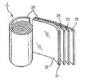
- FIG. 2 is an explanatory diagram illustrating an example of the capacitor element according to this embodiment.
- FIG. 3 is a graph showing values of leakage current during a high temperature load test of the electrolytic capacitors of Examples 13 and 14.
- FIG. 1 is a schematic cross-sectional view showing an example of an electrolytic capacitor according to this embodiment.
- FIG. 2 is an explanatory diagram illustrating an example of the capacitor element according to this embodiment.
- FIG. 3 is a graph showing values of leakage current during a high temperature load test of the electrolytic capacitors of Examples 13 and 14.
- FIG. 1 is a cross-sectional view schematically showing the overall configuration of an electrolytic capacitor according to this embodiment
- FIG. 2 is an explanatory diagram of a capacitor element.
- the capacitor element 1 is arranged inside a bottomed cylindrical exterior case 4 made of metal such as aluminum.
- the elastic sealing member 3 is fixed.
- Capacitor element 1 includes anode foil 20 having sintered aluminum powder 22 formed on the surface of core material (base material) 21 , cathode foil 23 , and a second electrode foil 23 disposed between anode foil 20 and cathode foil 23 .
- the wound capacitor element 1 is configured by winding one separator 24 and a second separator 25, and is sealed in an exterior case 4 after being impregnated with an electrolytic solution.
- Reference numeral 2 denotes lead wires attached to the anode foil 20 and the cathode foil 23, respectively.
- the sintered body 22 is formed on both sides or one side of the base material 21 .
- the sintered body 22 may also be formed on the cathode foil 23 (not shown).
- the base material 21 does not necessarily have to be included, and the anode foil 20 or the cathode foil 23 may be composed only of the sintered body 22 of aluminum powder.
- the present embodiment since the electrode foil has a surface area larger than the pit area of conventional etching foil, a large capacitance can be realized.
- the present embodiment has a structure in which a sintered body is wound in a foil shape, so that the distance between the anode and the cathode current collector is large. As it becomes closer, the resistance component through the electrolytic solution becomes smaller, and the capacitance at high frequencies (about 10 kHz) is excellent.
- the present embodiment is superior in capacitance at high frequencies (about 10 kHz) to electrolytic capacitors using foils to which fine aluminum powder is adhered (for example, Patent Documents 2 and 3).
- the sintered body 22 of powder refers to a sintered body composed of sintered grains of powder.
- the sintered grains mean sintered particles (referred to as “sintered grains” in the present application) obtained by sintering powder particles (referred to as “powder grains” in the present application).
- the aluminum powder sintered body 22 according to the present embodiment is composed of sintered grains of powder made of at least one of aluminum and an aluminum alloy.
- the aluminum and the aluminum in the aluminum alloy preferably have an aluminum purity of 99.8% by weight or more from the viewpoint of preventing problems caused by impurities. More preferably, the purity is 99.99% by weight or more.
- An alloy containing one or more of elements such as vanadium (V), gallium (Ga), nickel (Ni), boron (B) and zirconium (Zr) can be used.
- the content of each of these elements is preferably 100 ppm by weight or less, particularly 50 ppm by weight or less.
- the sintered body 22 is obtained by sintering sintered particles of powder made of at least one of aluminum and aluminum alloy while maintaining gaps between them. That is, each sintered grain is connected to each other while maintaining voids, and has a three-dimensional network structure.
- the porosity in this case can be appropriately set within a range of usually 10% or more depending on the desired capacitance and the like.
- the porosity can be controlled by, for example, the particle size of the starting material aluminum or aluminum alloy powder, the composition of the paste composition (resin binder) containing the powder, and the like.
- the shape of the sintered body 22 is not particularly limited, but in the case of the structure including the base material 21, it is generally preferable that the average thickness of one side is 5 ⁇ m or more and 100 ⁇ m or less, particularly 5 ⁇ m or more and 60 ⁇ m or less. .
- the average thickness can be calculated by a weight method.
- the average particle size of the sintered grains is preferably 80 ⁇ m or less. If the average particle size is more than 80 ⁇ m, the desired capacitance may not be obtained.
- the average particle size of the sintered grains is preferably 1 ⁇ m or more. If the average particle size is less than 1 ⁇ m, the desired withstand voltage may not be obtained.
- a smaller average particle size is more advantageous for increasing the surface area. may decrease. From the viewpoint of preventing such a decrease in capacitance, it is more preferable to set the average particle size to 2.5 ⁇ m or more. In particular, from the viewpoint of improving the capacitance characteristics around 10 kHz, the average particle size is preferably 2.5 ⁇ m or more and 6 ⁇ m or less.
- the substrate 21 is not particularly limited, but aluminum foil can be preferably used.
- the substrate 21 can be used without etching, but may be etched if necessary.
- aluminum foil as the substrate 21 aluminum or an aluminum alloy having the same composition as the powder of aluminum or aluminum alloy can be used. In particular, in order to suppress an increase in leakage current under high-temperature load, it is more preferable that the purity of aluminum is 99.99% by weight or more.
- the thickness of the aluminum foil as the base material 21 is not particularly limited, it is preferably in the range of 5 ⁇ m to 100 ⁇ m, particularly 5 ⁇ m to 60 ⁇ m.
- the method of forming the sintered body 22 on the base material 21 to form the electrode foil 20 (23) is as follows. i.e. 1. 1. A first step of forming a coating on the base material 21 from a composition containing powder of at least one of aluminum and aluminum alloy; A second step of sintering the film at a temperature of 560° C. or higher and 660° C. or lower is included.
- a film made of a composition containing powder of at least one of aluminum and aluminum alloy is formed on the substrate 21 .
- the composition (ingredients) of aluminum or an aluminum alloy those listed above can be used.
- the particle shape of the powder, that is, powder grains, is not particularly limited, and any of spherical, irregular, scale-like and the like can be suitably used, but spherical powder grains can be particularly suitably used.
- the powder, that is, the average particle size of powder grains is preferably 80 ⁇ m or less. If the average particle size is more than 80 ⁇ m, the desired capacitance may not be obtained.
- the powder, ie, the average particle size of powder grains is preferably 1 ⁇ m or more.
- the average particle size is less than 1 ⁇ m, the desired withstand voltage may not be obtained.
- a smaller average particle size is more advantageous for increasing the surface area. may decrease.
- the average particle size is preferably 2.5 ⁇ m or more and 6 ⁇ m or less.
- the particle size of the powder grains does not change significantly even after sintering in the second step, and by adjusting the average particle size of the powder grains, the average particle size of the sintered grains is adjusted to the same extent. be able to.
- the composition may contain resin binders, solvents, sintering aids, surfactants, etc., if necessary. Any of these can be known or commercially available.
- a paste composition containing at least one of a resin binder and a solvent. Thereby, a film can be efficiently formed.
- solvents can be used.
- organic solvents such as ethanol, toluene, ketones and esters can be used.
- the film is sintered at a temperature of 560°C or higher and 660°C or lower.
- the sintering temperature is 560° C. or higher and 660° C. or lower, preferably 560° C. or higher and lower than 660° C., more preferably 570° C. or higher and 659° C. or lower.
- the sintering time varies depending on the sintering temperature and the like, but can be appropriately determined within a range of about 5 to 24 hours.
- the sintering atmosphere is not particularly limited, and may be, for example, a vacuum atmosphere, an inert gas atmosphere, an oxidizing gas atmosphere (atmosphere), a reducing atmosphere, or the like. is preferred. Also, the pressure conditions may be normal pressure, reduced pressure or increased pressure.
- the temperature range is from 100° C. to 600° C. for a holding time of 5 hours or longer.
- Heat treatment is preferably performed.
- the heat treatment atmosphere is not particularly limited, and may be, for example, a vacuum atmosphere, an inert gas atmosphere, or an oxidizing gas atmosphere.
- the pressure condition may be normal pressure, reduced pressure or increased pressure.
- the electrode material of the present invention can be obtained in the second step. This can be used as the electrode (electrode foil 20 (23)) for the aluminum electrolytic capacitor 10 as it is without etching, but may be etched if necessary.
- the electrolyte preferably has a specific resistance of 1500 ⁇ cm or less.
- the ratio of the capacitance at 10 kHz to the capacitance at 120 Hz becomes closer to 1 than in the conventional case, and good capacitance characteristics can be obtained over a wide frequency range.
- the electrolyte preferably has a specific resistance of 100 ⁇ cm or more.
- the electrolytic solution of the present invention contains at least an electrolyte and a solvent. Additives described later may also be added.
- a solvent for dissolving the electrolyte and additives preferably an organic solvent can be used alone, or a water-organic solvent system, ie a mixture of an organic solvent and water, can be used. .
- protic solvents or aprotic solvents can be used alone or in combination of two or more. If necessary, one or more protic solvents and one or more aprotic solvents may be used in any combination.
- Suitable protic solvents include, for example, alcohol compounds. Specific examples of alcohol compounds that can be advantageously used here include, but are not limited to, monohydric alcohols such as methyl alcohol, ethyl alcohol, propyl alcohol, and butyl alcohol, ethylene glycol, and diethylene glycol listed below.
- dihydric alcohols such as triethylene glycol, polyethylene glycol, propylene glycol, dipropylene glycol, tripropylene glycol, polypropylene glycol, 1,4-butanediol and 1,3-butanediol, trihydric alcohols such as glycerin , or derivatives thereof.
- Suitable aprotic solvents include, but are not limited to, lactone compounds such as ⁇ -butyrolactone, ⁇ -valerolactone and ⁇ -valerolactone listed below, sulfolane, methylsulfolane, dimethylsulfolane, propylene carbonate, Ethylene carbonate, isobutylene carbonate, methylpyrrolidone, imidazolidinone, pyrrolidine, pyrrolidinone, methylpyrrolidinone, tetrahydrofuran, acetonitrile, N-methylformamide, N,N-dimethylformamide, nitrobenzene, their derivatives and other intramolecularly polarizable compounds. can be mentioned.
- a water-organic solvent system solvent can be used instead of using the organic solvent alone as described above.
- a water-organic solvent By using such a water-organic solvent, the freezing point of the solvent is lowered, thereby improving the resistivity characteristics of the electrolyte at low temperatures and reducing the difference in resistivity between low and room temperatures. It is possible to realize good low-temperature characteristics indicated by
- this proton-based organic solvent has a boiling point of 198°C and a melting point of about -13°C.
- the temperature range required for capacitors is generally -40°C to 105°C. Coagulation may degrade electrical properties.
- the electrolytic solution according to the present embodiment uses an organic solvent with excellent temperature characteristics alone or in a mixture of a plurality of kinds.
- a solvent-based solvent By using a solvent-based solvent, the freezing point of the solvent can be lowered to ensure electrical properties at low temperatures.
- this water-organic solvent-based electrolytic solution has a very high electrolyte dissolving power and ion mobility, it can realize a much lower specific resistance than an electrolytic solution containing only an organic solvent.
- the properties of the solvent are improved, so the electrolytic solution has an epoch-making property that the difference in resistivity between low temperature and room temperature is small. Therefore, the electrolytic capacitor 10 using such an electrolytic solution can of course have good temperature characteristics reflecting the characteristics of the electrolytic solution.
- organic acids preferably carboxylic acids or salts thereof, boron complexes of dicarboxylic acids or hydroxycarboxylic acids or salts thereof, and inorganic acids or salts thereof are used.
- These electrolyte components may be used alone, or two or more electrolyte components may be used in any combination.
- an inorganic acid or a salt thereof is used in combination with a carboxylic acid or a salt thereof, a boron complex of a dicarboxylic acid or a hydroxycarboxylic acid, or a salt thereof, as an electrolyte component, the freezing point of the electrolyte solution can be lowered, thereby improving the low-temperature properties of the electrolyte solution. can contribute to further improvement.
- carboxylic acids that can be used as electrolyte components include, but are not limited to, formic acid, acetic acid, propionic acid, butyric acid, p-nitrobenzoic acid, salicylic acid, benzoic acid, methylbenzoic acid, ethylbenzoic acid.
- Carboxylic acids containing hydroxyl groups and the like, such as citric acid can also be used.
- the dicarboxylic acid or hydroxycarboxylic acid in the boron complex of dicarboxylic acid or hydroxycarboxylic acid that can also be used as an electrolytic solution component is not limited to those listed below, but borodioxalic acid, borodimalonic acid, borodimalonic acid, acid, borodidipic acid, borodimaleic acid, borodiglycolic acid, borodilactic acid, borodimalic acid, boroditartaric acid, borodicitric acid, borodisalicylic acid, borodiphthalic acid, borodi(2-hydroxy)isobutyric acid, borodimandelic acid, borodi(3-hydroxy) Propionic acid and the like can be mentioned.
- inorganic acids that can also be used as electrolyte components include phosphoric acid, phosphorous acid, hypophosphorous acid, alkyl phosphoric acid, phosphomolybdic acid, boric acid, and sulfamine. Acids and the like can be mentioned. Derivatives of such inorganic acids may also be used, if desired.
- salts of the carboxylic acids or inorganic acids described above can be used as the salts of the carboxylic acids or inorganic acids described above.
- suitable salts include, but are not limited to, sodium salts, potassium salts, ammonium salts, alkylammonium salts, and one or more selected from amine salts and amidine salts listed below.
- Amidine salts include 1,3-dimethylimidazolinium, 1,3-diethylimidazolinium, 1,2,3-trimethylimidazolinium, 1,2,3,4-tetramethylimidazolinium, 1,3 -dimethyl-2-ethylimidazolinium, 1,2-dimethyl-3-ethylimidazolinium, 1,2-dimethyl-3-ethylimidazolinium, 1,2,3-triethylimidazolinium, 1,2 , 3,4-tetraethylimidazolinium.
- Examples include tetraalkylammonium salts, imidazolium salts, and the like.
- an inorganic acid or a salt thereof as an electrolyte component can be expected to lower the freezing point of the electrolyte, contributing to the improvement of the low-temperature characteristics of the electrolyte.
- an inorganic acid or a salt thereof if a nitro compound is used as an additive, there is a hydrogen gas absorption effect derived from the nitro compound.
- an electrolyte component such as an inorganic acid or a salt thereof in combination with an electrolyte component such as the carboxylic acid or a salt thereof
- the carboxylic acid or a salt thereof can be used alone.
- the life of the electrolytic capacitor 10 is remarkably extended.
- the amount of electrolyte contained in the electrolytic solution according to this embodiment can be appropriately determined according to conditions such as the properties required for the electrolytic solution, the type of solvent used, and the type of electrolyte used.
- a carboxylic acid or a salt thereof when used as an electrolyte, its amount should be about 3 to 30% by mass of the total weight of the electrolyte. If the amount of the electrolyte is less than 3% by mass, the desired conductivity cannot be sufficiently ensured, and if it exceeds 30% by mass, the effect is saturated and the electrolyte becomes difficult to dissolve in the solvent.
- the amount should be about 0.1 to 15% by mass of the total amount of the electrolyte. If the amount of the electrolyte is less than 0.1% by mass, the desired electrical conductivity cannot be sufficiently secured, and if it exceeds 15% by mass, the effect is saturated and the electrolyte becomes difficult to dissolve in the solvent. Also when a carboxylic acid or its salt and an inorganic acid or its salt are used in combination, they can be used within the above range.
- the electrolyte solution according to the present embodiment includes (1) a chelate compound, (2) sugars and derivatives thereof, (3) gluconic acid and (or) gluconolactone, (4) the nitro compound, (5) a polymer Additives such as chemical compounds are preferably added as required. These additives may be used alone, or two or more additives may be used in any combination. Each additive will be described below.
- Chelate compound Chelate compounds such as ethylenediaminetetraacetic acid (EDTA), trans-1,2-diaminocyclohexane-N,N,N',N',N'-tetraacetic acid-hydrate (CyDTA), dihydroxy ethylglycine (DHEG), ethylenediaminetetrakis(methylenephosphonic acid) (EDTPO), diethylenetriamine-N,N,N',N'',N''-pentaacetic acid (DTPA), diaminopropanoltetraacetic acid (DPTA-OH), Ethylenediaminediacetic acid (EDDA), ethylenediamine-N,N'-bis(methylenephosphonic acid) hemihydrate (EDDPO), glycol etherdiaminetetraacetic acid (GEDTA), hydroxyethylethylenediaminetriacetic acid (EDTA-OH), etc.
- EDTA ethylenediaminetetraacetic acid
- the chelate compound in the range of 0.01 to 3% by mass.
- Such a chelate compound extends the life of the capacitor 10 by suppressing the hydration reaction of the aluminum (Al) electrode foil of the low impedance capacitor, and improves the low temperature characteristics of the electrolytic capacitor 10 (because the solvent has a composition close to the non-freezing state, The change in impedance between room temperature and low temperature is small) and corrosion resistance can be improved.
- sugars and derivatives thereof examples include monosaccharides such as glucose, fructose, xylose, galactose, ribose, mannose, arabinose, lyxose, allose, altose, gulose, idostallose, derivatives thereof, and erythritol.
- sugar alcohols such as mannitol, disaccharides such as maltose, sucrose, lactose, cellobiose, sucrose, agarobiose and their derivatives, trisaccharides such as maltotriose and their derivatives, starch, glycogen, alginic acid, agar, polysaccharides such as mannan, derivatives thereof, and the like. It is generally preferable to add sugars and derivatives thereof in the range of 0.01 to 5% by mass.
- Such sugars and their derivatives are useful for extending the life of the capacitor 10 by suppressing the hydration reaction of the electrode foils of the low-impedance capacitor, suppressing the decomposition and activation of electrolytes such as carboxylic acids by adding sugars and their derivatives, and electrolysis. Effects such as improvement of the low-temperature characteristics of the capacitor 10 (because the solvent has a composition close to the non-freezing state, the change in impedance between room temperature and low temperature becomes small) can be brought about.
- the electrolytic solution according to the present embodiment can contain gluconic acid, gluconolactone, and the like alone or in combination, if necessary.
- Additives of this type are generally preferably added in the range of 0.01 to 5% by weight.
- the electrolytic solution according to the present embodiment may optionally contain nitrophenol such as p-nitrophenol, nitrobenzoic acid such as p-nitrobenzoic acid, dinitrobenzoic acid, nitroacetophenone such as p-nitro. It may contain at least one nitro compound selected from the group of compounds such as acetophenone, nitroanisole, nitrobenzyl alcohol.
- the nitro compound is preferably added in an amount of 0.01 to 5% by mass based on the total amount of the electrolytic solution. If the amount of the nitro compound added is less than 0.01% by mass, the desired effect can hardly be obtained. In some cases, it is conceivable that other characteristics may be adversely affected.
- Polymer compound examples include water-soluble silicone, polyacrylic acid and its derivatives, polymethacrylic acid and its derivatives, polyacrylamide and its derivatives, polyglutamic acid and its derivatives, polyglycerin and its derivatives, polyethylene glycol and its derivatives. Derivatives such as polypropylene glycol and its derivatives, polyvinyl alcohol and its derivatives can be used. Such a polymer compound can bring about effects according to the action of each polymer compound, such as improvement of the withstand voltage characteristics of the electrolytic capacitor 10 and extension of the life of the electrolytic capacitor 10 .
- a wide range of molecular weight polymer compounds can be used, from relatively low molecular weight (oligomers) to high molecular weight, depending on the action of each polymer compound, solubility and dispersibility in solvents, and desired effects. can.
- the electrolytic solution according to the present embodiment may further contain additives commonly used in the field of aluminum electrolytic capacitors or other electrolytic capacitors, in addition to the additives described above.
- Suitable additives include, for example, silane coupling agents, polymer electrolytes, colloidal silica, and the like.
- the separators 24 and 25 are not particularly limited, they are preferably made of naturally occurring cellulose materials such as manila hemp or vegetable pulp, and the raw material pulp is subjected to a dust removal process, a washing process, and a beating process. Those manufactured through a process, a papermaking process, etc. can be advantageously used. Also usable are woven fabrics, non-woven fabrics, sheets and films made from synthetic fibers such as rayon, nylon, polyester, polyvinyl compounds, aramid, acryl, and polyurethane. In addition, it is also possible to use a mixed product of natural fibers and synthetic fibers, a blended product, and the like.
- non-heat-treated aluminum with a purity of 99.0% or higher e.g., non-heat-treated material of aluminum 1100
- heat-treated aluminum with a purity of 99.0% or higher e.g., H22 material of 1000 series aluminum
- manganese (Mn) and/or magnesium (Mg) containing aluminum alloy refining material for example, aluminum alloy 3003 O material, 3000 series aluminum alloy H22 material, aluminum alloy 3004 O material
- the sealing member 3 used in the electrolytic capacitor 10 of the present embodiment is made of a material having high hardness, moderate rubber elasticity, impermeability to the electrolyte, and excellent airtightness as the sealing member 3. As long as it can be formed from various conventional materials. Suitable sealing member 3 materials include, for example, elastic rubbers such as natural rubber (NR), styrene-butadiene rubber (SBR), ethylene-propylene terpolymer (EPT), and isobutylene-isoprene rubber (IIR). . In particular, isobutylene-isoprene rubber (IIR) is suitable because it has high airtightness and does not permeate the electrolytic solution as vapor.
- NR natural rubber
- SBR styrene-butadiene rubber
- EPT ethylene-propylene terpolymer
- IIR isobutylene-isoprene rubber
- IIR is suitable because it has high airtightness and does not permeate the electrolytic
- IIRs having better heat resistance such as sulfur vulcanization, quinoid vulcanization, resin vulcanization, peroxide vulcanization, and the like.
- high-hardness rubber As for the hardness, by using a sealing rubber having a hardness of 80 (IRHD/M) or more in rubber hardness measurement (30-second value) with an IRHD hardness tester, mechanical stress is less likely to be applied, and an increase in leakage current is suppressed. can do.
- a hybrid material in which an airtight and sufficiently high-strength resin material plate (for example, a fluororesin plate such as a PTFE plate) and elastic rubber are adhered together is also advantageous. can be used for
- the lead wire 2 used as an external connection terminal or an external electrode terminal and inserted into the lead wire through-hole of the sealing body 3 is made of iron, copper, tin, lead, silver, gold, zinc, bismuth, tungsten, nickel, It can be formed from various metallic materials such as titanium and chromium.
- the lead wire 2 is advantageous to form the lead wire 2 from a highly conductive metallic material such as copper, silver, iron, gold, etc., especially copper wire or silver wire.
- Example 1 an aluminum electrolytic capacitor with a wound structure was produced according to the following procedure.
- An anode foil of an aluminum powder sintered body was produced by the manufacturing method (first to third steps) disclosed above, and then a lead wire for leading out an electrode was attached. Also, another aluminum foil was electrochemically etched to prepare a cathode foil, and then a lead wire for leading out the electrode was attached. Subsequently, a capacitor element was produced by winding a separator (separating paper) between the anode foil and the cathode foil.
- an electrolytic solution was prepared by sequentially adding a solvent component and an electrolyte component to a fixed container and then stirring and dissolving them.
- the capacitor element was impregnated with the electrolytic solution produced by the above preparation method, it was housed in an aluminum case with a bottom so that the lead wire for leading out the electrode protruded from the case, and the opening of this case was sealed with an elastic sealing member.
- a post-aging treatment was performed to produce an electrolytic capacitor having a wound structure.
- Comparative example 1 In Comparative Example 1, after an aluminum foil was electrochemically etched, an oxide film was formed on the surface by anodizing, and this was used as an anode foil. Other electrolytic capacitor manufacturing methods were the same as those described in Example 1 above.
- Example 1 In both Example 1 and Comparative Example 1, samples with a foil withstand voltage equivalent to 400 WV in capacitor withstand voltage were produced.
- Example 1 the capacitances of the electrolytic capacitors produced in Example 1 and Comparative Example 1 were measured at 25°C at frequencies of 120 Hz and 10 kHz, and the measured values shown in Table 1 below were obtained.
- Examples 2-12 Next, the relationship between the specific resistance of the electrolytic solution and the capacitance of the capacitor is compared for capacitors manufactured by the same method as in Example 1 at average powder particle sizes of 2.5 ⁇ m and 6 ⁇ m.
- the electrolytic capacitors of Examples 2 to 12 were prepared by repeating the same method as in Example 1, and the electrolytic solution was prepared using the same components as in Example 1, and the specific resistance was 100 ⁇ cm by adjusting the composition. , 30° C. to 2000 ⁇ cm, and 30° C., respectively. Samples with an average powder particle diameter of 2.5 ⁇ m and a capacitor with an average powder particle diameter of 6 ⁇ m were prepared to have a withstand voltage of 400 WV and a foil withstand voltage of 450 WV, respectively.
- Comparative Examples 2-12 The same method as in Comparative Example 1 was repeated as the method for producing capacitors of etched aluminum foil used in Comparative Examples 2 to 12, and the method for producing the electrolytic solution was the same as in Examples 2 to 12 above. As in Examples 2 to 12, samples with a capacitor withstand voltage of 400 WV and 450 WV were produced.
- Tables 2 and 3 list the capacitance at 120 Hz and 10 kHz.
- a typical use of capacitors is for smoothing the primary side of switching power supplies.
- MOS-FETs that repeat switching at a frequency of around 10 kHz in the latter stage of the circuit It also has the role of absorbing current noise from elements such as This noise is called EMI, and since it adversely affects other electrical equipment through commercial power lines, it is regulated by the EMC Directive (89/336/EEC). Increasing the capacitance near 10 kHz is important because it contributes to this noise reduction.
- the capacitance ratio at 120 Hz and 10 kHz shown in Tables 2 and 3 when the specific resistance of the electrolyte is 100 ⁇ cm to 1500 ⁇ cm, the aluminum powder sintered foil has a higher value than the etched foil. showing. At 2000 ⁇ cm, the sintered powder foil shows a lower value than the etched foil. It is considered that this is because particles are aggregated rather than pits, and the path length to the depths of the pits is long, so that when an electrolytic solution with a high specific resistance is used, it becomes difficult to obtain capacitance at high frequencies.
- an aluminum electrolytic capacitor if a foil of a sintered aluminum powder is combined with an electrolytic solution having a specific resistance of 1500 ⁇ cm or less, a 10 kHz capacitance against a 120 Hz capacitance can be obtained more easily than the conventionally used aluminum etched foil.
- Example 13 the relationship between the purity of the aluminum substrate and the life of the capacitor is compared.
- the electrolytic capacitor of Example 13 was produced using an aluminum powder sintered foil whose base material had an aluminum purity of 99.99% by weight or more and whose powder had an aluminum purity of 99.99% by weight or more, For other capacitor fabrication methods, the method described in Example 1 was repeated. Further, in the electrolytic capacitor of Example 14, aluminum powder sintered in which the aluminum purity of the base material is 99.8% by weight or more and less than 99.95% by weight, and the aluminum purity of the powder is 99.99% by weight or more A body foil was used for fabrication, and the method described in Example 1 was repeated for other capacitor fabrication methods.
- FIG. 3 shows the value of the leakage current of the electrolytic capacitor during the high temperature load test.
- the leakage current was suppressed to less than 12 ⁇ A in all the capacitors according to the examples, but especially the capacitor with a base material purity of 99.99% by weight or more (Example 13) tends to increase the leakage current after 3000 hours. is not observed, and the increase in leakage current is suppressed.
- An increase in leakage current leads to an increase in the amount of gas generated inside the capacitor, and the internal pressure gradually rises, increasing the risk of early valve actuation.
- the aluminum purity of the base material is 99.99% by weight or more. Also, for the aluminum powder that is electrically connected to the base material, it is clear that the purity of aluminum is preferably 99.99% by weight or more for the same reason.
- the "average particle size (D50)" means the particle size at 50% of the integrated value in the volume-based particle size distribution determined by the laser diffraction/scattering method.
Landscapes
- Engineering & Computer Science (AREA)
- Power Engineering (AREA)
- Microelectronics & Electronic Packaging (AREA)
- Chemical & Material Sciences (AREA)
- Chemical Kinetics & Catalysis (AREA)
- Electrochemistry (AREA)
- Materials Engineering (AREA)
- Fixed Capacitors And Capacitor Manufacturing Machines (AREA)
Priority Applications (15)
| Application Number | Priority Date | Filing Date | Title |
|---|---|---|---|
| JP2022547732A JP7168823B1 (ja) | 2021-07-15 | 2021-07-15 | 電解コンデンサ |
| CN202190000954.6U CN221861469U (zh) | 2021-07-15 | 2021-07-15 | 电解电容器 |
| PCT/JP2021/026547 WO2023286226A1 (ja) | 2021-07-15 | 2021-07-15 | 電解コンデンサ |
| PCT/JP2022/022316 WO2023286482A1 (ja) | 2021-07-15 | 2022-06-01 | 電解コンデンサおよび電解コンデンサの製造方法 |
| CN202280040645.0A CN117480583A (zh) | 2021-07-15 | 2022-06-01 | 电解电容器和电解电容器的制造方法 |
| JP2023535174A JPWO2023286482A1 (https=) | 2021-07-15 | 2022-06-01 | |
| EP22841998.2A EP4343800A4 (en) | 2021-07-15 | 2022-07-05 | ELECTROLYTIC CAPACITOR |
| CN202411578961.0A CN119560313A (zh) | 2021-07-15 | 2022-07-05 | 电解电容器 |
| US18/569,030 US12500041B2 (en) | 2021-07-15 | 2022-07-05 | Electrolytic capacitor |
| JP2023535254A JP7840329B2 (ja) | 2021-07-15 | 2022-07-05 | 電解コンデンサ |
| CN202280008571.2A CN116802759A (zh) | 2021-07-15 | 2022-07-05 | 电解电容器 |
| PCT/JP2022/026649 WO2023286654A1 (ja) | 2021-07-15 | 2022-07-05 | 電解コンデンサ |
| KR1020247000250A KR20240024892A (ko) | 2021-07-15 | 2022-07-05 | 전해 콘덴서 |
| TW111126421A TWI854256B (zh) | 2021-07-15 | 2022-07-14 | 電解電容器 |
| JP2022171245A JP2023014075A (ja) | 2021-07-15 | 2022-10-26 | 電解コンデンサ |
Applications Claiming Priority (1)
| Application Number | Priority Date | Filing Date | Title |
|---|---|---|---|
| PCT/JP2021/026547 WO2023286226A1 (ja) | 2021-07-15 | 2021-07-15 | 電解コンデンサ |
Publications (1)
| Publication Number | Publication Date |
|---|---|
| WO2023286226A1 true WO2023286226A1 (ja) | 2023-01-19 |
Family
ID=83977441
Family Applications (3)
| Application Number | Title | Priority Date | Filing Date |
|---|---|---|---|
| PCT/JP2021/026547 Ceased WO2023286226A1 (ja) | 2021-07-15 | 2021-07-15 | 電解コンデンサ |
| PCT/JP2022/022316 Ceased WO2023286482A1 (ja) | 2021-07-15 | 2022-06-01 | 電解コンデンサおよび電解コンデンサの製造方法 |
| PCT/JP2022/026649 Ceased WO2023286654A1 (ja) | 2021-07-15 | 2022-07-05 | 電解コンデンサ |
Family Applications After (2)
| Application Number | Title | Priority Date | Filing Date |
|---|---|---|---|
| PCT/JP2022/022316 Ceased WO2023286482A1 (ja) | 2021-07-15 | 2022-06-01 | 電解コンデンサおよび電解コンデンサの製造方法 |
| PCT/JP2022/026649 Ceased WO2023286654A1 (ja) | 2021-07-15 | 2022-07-05 | 電解コンデンサ |
Country Status (7)
| Country | Link |
|---|---|
| US (1) | US12500041B2 (https=) |
| EP (1) | EP4343800A4 (https=) |
| JP (4) | JP7168823B1 (https=) |
| KR (1) | KR20240024892A (https=) |
| CN (4) | CN221861469U (https=) |
| TW (1) | TWI854256B (https=) |
| WO (3) | WO2023286226A1 (https=) |
Cited By (1)
| Publication number | Priority date | Publication date | Assignee | Title |
|---|---|---|---|---|
| JP2026008537A (ja) * | 2024-06-28 | 2026-01-19 | ティーディーケイ・エレクトロニクス・アクチェンゲゼルシャフト | 電解質、キャパシタ、及びoccを測定する方法 |
Families Citing this family (5)
| Publication number | Priority date | Publication date | Assignee | Title |
|---|---|---|---|---|
| CN116053043A (zh) * | 2023-02-21 | 2023-05-02 | 西安交通大学 | 铝电解电容器阳极箔及其还原性气氛辅助烧结制备方法 |
| TWI872839B (zh) * | 2023-12-01 | 2025-02-11 | 國立虎尾科技大學 | 薄膜式超級電容 |
| WO2025205661A1 (ja) * | 2024-03-28 | 2025-10-02 | 日本ケミコン株式会社 | 電解コンデンサ及び製造方法 |
| DE102024116962A1 (de) * | 2024-06-17 | 2025-12-18 | Tdk Electronics Ag | Kondensator und Verfahren zur Herstellung eines Kondensators |
| CN119153237B (zh) * | 2024-11-21 | 2025-02-25 | 南通海星电子股份有限公司 | 一种铝电解电容器用高强度烧结箔的制备方法 |
Citations (3)
| Publication number | Priority date | Publication date | Assignee | Title |
|---|---|---|---|---|
| JP2005019773A (ja) * | 2003-06-27 | 2005-01-20 | Nichicon Corp | アルミニウム電解コンデンサ |
| JP2008098279A (ja) * | 2006-10-10 | 2008-04-24 | Toyo Aluminium Kk | アルミニウム電解コンデンサ用電極材及びその製造方法 |
| WO2019026701A1 (ja) * | 2017-08-01 | 2019-02-07 | 日立化成株式会社 | 電解コンデンサ用の電極、電解コンデンサ用の電極の製造方法、及び電解コンデンサ |
Family Cites Families (22)
| Publication number | Priority date | Publication date | Assignee | Title |
|---|---|---|---|---|
| JPS59140430U (ja) | 1983-03-09 | 1984-09-19 | マルコン電子株式会社 | 焼結形電解コンデンサ |
| JPH02267916A (ja) | 1989-04-07 | 1990-11-01 | Matsushita Electric Ind Co Ltd | アルミ電解コンデンサ |
| JPH0782966B2 (ja) | 1990-04-24 | 1995-09-06 | 信英通信工業株式会社 | 電解コンデンサ駆動用電解液 |
| JPH0442911A (ja) * | 1990-06-06 | 1992-02-13 | Elna Co Ltd | 電解コンデンサ駆動用電解液 |
| JPH04101406A (ja) * | 1990-08-20 | 1992-04-02 | Nec Corp | チップ型固体電解タンタルコンデンサ |
| JP2773446B2 (ja) | 1991-03-13 | 1998-07-09 | 日立エーアイシー株式会社 | 電解コンデンサ用電解液 |
| JP3085022B2 (ja) | 1993-04-28 | 2000-09-04 | 日立エーアイシー株式会社 | 電解コンデンサ用電解液 |
| US6493211B1 (en) | 1999-03-17 | 2002-12-10 | Nippon Chemi-Con Corporation | Electrolyte for electrolytic capacitor |
| JP2005303062A (ja) | 2004-04-13 | 2005-10-27 | Rubycon Corp | 電解コンデンサ駆動用電解液及び電解コンデンサ |
| JP2006108159A (ja) | 2004-09-30 | 2006-04-20 | Nippon Chemicon Corp | 電解コンデンサ |
| JP4911509B2 (ja) * | 2007-04-03 | 2012-04-04 | 三洋電機株式会社 | 電解コンデンサおよびその製造方法 |
| CN102017034B (zh) | 2008-04-22 | 2016-01-27 | 东洋铝株式会社 | 用于铝电解电容器的电极材料和制造该电极材料的方法 |
| TWI447766B (zh) * | 2009-03-31 | 2014-08-01 | Nippon Chemicon | Electrolyte for Aluminum Electrolytic Capacitors and Aluminum Electrolytic Capacitors |
| JP5769528B2 (ja) * | 2011-07-15 | 2015-08-26 | 東洋アルミニウム株式会社 | アルミニウム電解コンデンサ用電極材及びその製造方法 |
| KR102079032B1 (ko) | 2012-02-10 | 2020-02-19 | 도요 알루미늄 가부시키가이샤 | 알루미늄 전해 콘덴서용 전극재의 제조방법 |
| JP2017076699A (ja) * | 2015-10-15 | 2017-04-20 | 宇部興産株式会社 | アルミ電解コンデンサ用電解液及びそれを用いたアルミ電解コンデンサ |
| DE112016005410T5 (de) | 2015-11-27 | 2018-09-20 | Panasonic Intellectual Property Management Co., Ltd. | Elektrolytkondensator und Verfahren zur seiner Herstellung |
| JP6735553B2 (ja) * | 2015-12-10 | 2020-08-05 | 日本軽金属株式会社 | アルミニウム電解コンデンサ用電極の製造方法 |
| JP2017188640A (ja) * | 2016-03-31 | 2017-10-12 | 出光興産株式会社 | 電解液並びにそれを用いた蓄電デバイス及び電界コンデンサ |
| JP6759067B2 (ja) * | 2016-11-18 | 2020-09-23 | 日本軽金属株式会社 | アルミニウム電解コンデンサ用電極の製造方法 |
| JP7384161B2 (ja) * | 2018-08-01 | 2023-11-21 | 日本ケミコン株式会社 | 電解コンデンサ用電解液及び電解コンデンサ |
| CN109994318B (zh) * | 2019-03-06 | 2021-01-26 | 湖南艾华集团股份有限公司 | 一种铝电解电容器及其制备方法 |
-
2021
- 2021-07-15 WO PCT/JP2021/026547 patent/WO2023286226A1/ja not_active Ceased
- 2021-07-15 JP JP2022547732A patent/JP7168823B1/ja active Active
- 2021-07-15 CN CN202190000954.6U patent/CN221861469U/zh active Active
-
2022
- 2022-06-01 CN CN202280040645.0A patent/CN117480583A/zh active Pending
- 2022-06-01 WO PCT/JP2022/022316 patent/WO2023286482A1/ja not_active Ceased
- 2022-06-01 JP JP2023535174A patent/JPWO2023286482A1/ja active Pending
- 2022-07-05 CN CN202411578961.0A patent/CN119560313A/zh active Pending
- 2022-07-05 JP JP2023535254A patent/JP7840329B2/ja active Active
- 2022-07-05 EP EP22841998.2A patent/EP4343800A4/en active Pending
- 2022-07-05 US US18/569,030 patent/US12500041B2/en active Active
- 2022-07-05 WO PCT/JP2022/026649 patent/WO2023286654A1/ja not_active Ceased
- 2022-07-05 CN CN202280008571.2A patent/CN116802759A/zh active Pending
- 2022-07-05 KR KR1020247000250A patent/KR20240024892A/ko active Pending
- 2022-07-14 TW TW111126421A patent/TWI854256B/zh active
- 2022-10-26 JP JP2022171245A patent/JP2023014075A/ja active Pending
Patent Citations (3)
| Publication number | Priority date | Publication date | Assignee | Title |
|---|---|---|---|---|
| JP2005019773A (ja) * | 2003-06-27 | 2005-01-20 | Nichicon Corp | アルミニウム電解コンデンサ |
| JP2008098279A (ja) * | 2006-10-10 | 2008-04-24 | Toyo Aluminium Kk | アルミニウム電解コンデンサ用電極材及びその製造方法 |
| WO2019026701A1 (ja) * | 2017-08-01 | 2019-02-07 | 日立化成株式会社 | 電解コンデンサ用の電極、電解コンデンサ用の電極の製造方法、及び電解コンデンサ |
Cited By (1)
| Publication number | Priority date | Publication date | Assignee | Title |
|---|---|---|---|---|
| JP2026008537A (ja) * | 2024-06-28 | 2026-01-19 | ティーディーケイ・エレクトロニクス・アクチェンゲゼルシャフト | 電解質、キャパシタ、及びoccを測定する方法 |
Also Published As
| Publication number | Publication date |
|---|---|
| CN119560313A (zh) | 2025-03-04 |
| JP7168823B1 (ja) | 2022-11-09 |
| JPWO2023286482A1 (https=) | 2023-01-19 |
| CN116802759A (zh) | 2023-09-22 |
| JPWO2023286654A1 (https=) | 2023-01-19 |
| JP7840329B2 (ja) | 2026-04-03 |
| CN221861469U (zh) | 2024-10-18 |
| US12500041B2 (en) | 2025-12-16 |
| JPWO2023286226A1 (https=) | 2023-01-19 |
| TW202312199A (zh) | 2023-03-16 |
| WO2023286654A1 (ja) | 2023-01-19 |
| EP4343800A1 (en) | 2024-03-27 |
| EP4343800A4 (en) | 2025-07-09 |
| TWI854256B (zh) | 2024-09-01 |
| CN117480583A (zh) | 2024-01-30 |
| JP2023014075A (ja) | 2023-01-26 |
| WO2023286482A1 (ja) | 2023-01-19 |
| US20240282534A1 (en) | 2024-08-22 |
| KR20240024892A (ko) | 2024-02-26 |
Similar Documents
| Publication | Publication Date | Title |
|---|---|---|
| JP7168823B1 (ja) | 電解コンデンサ | |
| KR100386984B1 (ko) | 전해 콘덴서 구동용 전해액 및 전해 콘덴서 | |
| JP2005303062A (ja) | 電解コンデンサ駆動用電解液及び電解コンデンサ | |
| JPWO2010050558A1 (ja) | コンデンサ素子の製造方法 | |
| TW202215462A (zh) | 陰極體以及電解電容器 | |
| JP2014072465A (ja) | 電解コンデンサ用電解液及び電解コンデンサ | |
| JP6403006B2 (ja) | 電解コンデンサ用電解液及び電解コンデンサ | |
| JP2000228332A (ja) | 電解コンデンサ駆動用電解液及びこれを用いた電解コンデンサ | |
| JPH11126732A (ja) | アルミニウム電解コンデンサ | |
| KR20250012654A (ko) | 전해 콘덴서 및 전해 콘덴서의 제조 방법 | |
| CN114093675A (zh) | 600v超高压铝电解电容器用电解液及其制备方法和在铝电解电容器中的应用 | |
| JP2019029598A (ja) | アルミニウム電解コンデンサ用電解液およびアルミニウム電解コンデンサ | |
| JP3623115B2 (ja) | 電解コンデンサ駆動用電解液及びこれを用いた電解コンデンサ | |
| CN116564714B (zh) | 一种超低温中高压引线式铝电解电容器 | |
| JP4822671B2 (ja) | 電解コンデンサ駆動用電解液及びこれを使用した電解コンデンサ | |
| JP3366267B2 (ja) | 電解コンデンサ駆動用電解液及びこれを用いた電解コンデンサ | |
| JP4913670B2 (ja) | 電解コンデンサの駆動用電解液、およびこれを用いた電解コンデンサ | |
| JP3609068B2 (ja) | 電解コンデンサ駆動用電解液及びこれを使用した電解コンデンサ | |
| KR20030034977A (ko) | 저전압 알루미늄 전해 콘덴서용 전해액 및 이를 함유하는전해콘덴서 | |
| JP2024010870A (ja) | 電解コンデンサ | |
| JP2026009801A (ja) | 電解コンデンサ用電解液、電解コンデンサ及び電解コンデンサの製造方法 | |
| JP3552485B2 (ja) | アルミ電解コンデンサ | |
| JP2009267338A (ja) | 電極体および電気二重層キャパシタ | |
| JP2008300711A (ja) | 電解コンデンサの駆動用電解液、およびこれを用いた電解コンデンサ | |
| JP2003059773A (ja) | 電解コンデンサ駆動用電解液及びこれを用いた電解コンデンサ |
Legal Events
| Date | Code | Title | Description |
|---|---|---|---|
| ENP | Entry into the national phase |
Ref document number: 2022547732 Country of ref document: JP Kind code of ref document: A |
|
| 121 | Ep: the epo has been informed by wipo that ep was designated in this application |
Ref document number: 21950165 Country of ref document: EP Kind code of ref document: A1 |
|
| WWE | Wipo information: entry into national phase |
Ref document number: 202190000954.6 Country of ref document: CN |
|
| NENP | Non-entry into the national phase |
Ref country code: DE |
|
| 122 | Ep: pct application non-entry in european phase |
Ref document number: 21950165 Country of ref document: EP Kind code of ref document: A1 |