WO2023286226A1 - 電解コンデンサ - Google Patents
電解コンデンサ Download PDFInfo
- Publication number
- WO2023286226A1 WO2023286226A1 PCT/JP2021/026547 JP2021026547W WO2023286226A1 WO 2023286226 A1 WO2023286226 A1 WO 2023286226A1 JP 2021026547 W JP2021026547 W JP 2021026547W WO 2023286226 A1 WO2023286226 A1 WO 2023286226A1
- Authority
- WO
- WIPO (PCT)
- Prior art keywords
- acid
- foil
- aluminum
- electrolytic
- electrolytic capacitor
- Prior art date
Links
- 239000003990 capacitor Substances 0.000 title claims abstract description 90
- 239000011888 foil Substances 0.000 claims abstract description 84
- XAGFODPZIPBFFR-UHFFFAOYSA-N aluminium Chemical compound [Al] XAGFODPZIPBFFR-UHFFFAOYSA-N 0.000 claims abstract description 61
- 229910052782 aluminium Inorganic materials 0.000 claims abstract description 47
- 239000008151 electrolyte solution Substances 0.000 claims abstract description 39
- 239000000843 powder Substances 0.000 claims abstract description 31
- 229910000838 Al alloy Inorganic materials 0.000 claims abstract description 17
- 239000003792 electrolyte Substances 0.000 claims description 36
- 239000002245 particle Substances 0.000 claims description 34
- 239000000463 material Substances 0.000 claims description 28
- 239000002904 solvent Substances 0.000 claims description 23
- 239000000203 mixture Substances 0.000 claims description 20
- -1 organic acid salt Chemical class 0.000 claims description 20
- 239000003960 organic solvent Substances 0.000 claims description 17
- 150000007522 mineralic acids Chemical class 0.000 claims description 14
- XLYOFNOQVPJJNP-UHFFFAOYSA-N water Substances O XLYOFNOQVPJJNP-UHFFFAOYSA-N 0.000 claims description 6
- 150000007524 organic acids Chemical class 0.000 claims description 5
- 238000005530 etching Methods 0.000 abstract description 14
- 239000007772 electrode material Substances 0.000 abstract description 3
- 239000000243 solution Substances 0.000 abstract 1
- 238000000034 method Methods 0.000 description 18
- 150000003839 salts Chemical class 0.000 description 18
- 239000002253 acid Substances 0.000 description 17
- 150000001875 compounds Chemical class 0.000 description 15
- 150000002828 nitro derivatives Chemical class 0.000 description 12
- 239000000654 additive Substances 0.000 description 11
- 239000012298 atmosphere Substances 0.000 description 10
- 230000000052 comparative effect Effects 0.000 description 10
- 238000007789 sealing Methods 0.000 description 9
- 238000005245 sintering Methods 0.000 description 9
- 230000000694 effects Effects 0.000 description 8
- 238000004519 manufacturing process Methods 0.000 description 7
- 229920000642 polymer Polymers 0.000 description 7
- RGHNJXZEOKUKBD-SQOUGZDYSA-N D-gluconic acid Chemical compound OC[C@@H](O)[C@@H](O)[C@H](O)[C@@H](O)C(O)=O RGHNJXZEOKUKBD-SQOUGZDYSA-N 0.000 description 6
- LYCAIKOWRPUZTN-UHFFFAOYSA-N Ethylene glycol Chemical compound OCCO LYCAIKOWRPUZTN-UHFFFAOYSA-N 0.000 description 6
- OFOBLEOULBTSOW-UHFFFAOYSA-N Malonic acid Chemical compound OC(=O)CC(O)=O OFOBLEOULBTSOW-UHFFFAOYSA-N 0.000 description 6
- RWRDLPDLKQPQOW-UHFFFAOYSA-N Pyrrolidine Chemical compound C1CCNC1 RWRDLPDLKQPQOW-UHFFFAOYSA-N 0.000 description 6
- 230000007423 decrease Effects 0.000 description 6
- 229920001971 elastomer Polymers 0.000 description 6
- 238000007710 freezing Methods 0.000 description 6
- 230000008014 freezing Effects 0.000 description 6
- WABPQHHGFIMREM-UHFFFAOYSA-N lead(0) Chemical compound [Pb] WABPQHHGFIMREM-UHFFFAOYSA-N 0.000 description 6
- 239000011347 resin Substances 0.000 description 6
- 229920005989 resin Polymers 0.000 description 6
- 239000005060 rubber Substances 0.000 description 6
- 235000000346 sugar Nutrition 0.000 description 6
- 150000008163 sugars Chemical class 0.000 description 6
- LFQSCWFLJHTTHZ-UHFFFAOYSA-N Ethanol Chemical compound CCO LFQSCWFLJHTTHZ-UHFFFAOYSA-N 0.000 description 5
- XEEYBQQBJWHFJM-UHFFFAOYSA-N Iron Chemical compound [Fe] XEEYBQQBJWHFJM-UHFFFAOYSA-N 0.000 description 5
- PXHVJJICTQNCMI-UHFFFAOYSA-N Nickel Chemical compound [Ni] PXHVJJICTQNCMI-UHFFFAOYSA-N 0.000 description 5
- NBIIXXVUZAFLBC-UHFFFAOYSA-N Phosphoric acid Chemical compound OP(O)(O)=O NBIIXXVUZAFLBC-UHFFFAOYSA-N 0.000 description 5
- 150000001298 alcohols Chemical class 0.000 description 5
- 150000001732 carboxylic acid derivatives Chemical class 0.000 description 5
- 150000001735 carboxylic acids Chemical class 0.000 description 5
- 239000013522 chelant Substances 0.000 description 5
- 235000019441 ethanol Nutrition 0.000 description 5
- 239000011133 lead Substances 0.000 description 5
- 239000000758 substrate Substances 0.000 description 5
- RYGMFSIKBFXOCR-UHFFFAOYSA-N Copper Chemical compound [Cu] RYGMFSIKBFXOCR-UHFFFAOYSA-N 0.000 description 4
- YNAVUWVOSKDBBP-UHFFFAOYSA-N Morpholine Chemical compound C1COCCN1 YNAVUWVOSKDBBP-UHFFFAOYSA-N 0.000 description 4
- 239000011230 binding agent Substances 0.000 description 4
- BVKZGUZCCUSVTD-UHFFFAOYSA-N carbonic acid Chemical class OC(O)=O BVKZGUZCCUSVTD-UHFFFAOYSA-N 0.000 description 4
- 239000010949 copper Substances 0.000 description 4
- XBDQKXXYIPTUBI-UHFFFAOYSA-N dimethylselenoniopropionate Natural products CCC(O)=O XBDQKXXYIPTUBI-UHFFFAOYSA-N 0.000 description 4
- 230000006872 improvement Effects 0.000 description 4
- 239000011777 magnesium Substances 0.000 description 4
- 239000011572 manganese Substances 0.000 description 4
- 230000008569 process Effects 0.000 description 4
- QTBSBXVTEAMEQO-UHFFFAOYSA-N Acetic acid Chemical compound CC(O)=O QTBSBXVTEAMEQO-UHFFFAOYSA-N 0.000 description 3
- WEVYAHXRMPXWCK-UHFFFAOYSA-N Acetonitrile Chemical compound CC#N WEVYAHXRMPXWCK-UHFFFAOYSA-N 0.000 description 3
- ZOXJGFHDIHLPTG-UHFFFAOYSA-N Boron Chemical compound [B] ZOXJGFHDIHLPTG-UHFFFAOYSA-N 0.000 description 3
- RGHNJXZEOKUKBD-UHFFFAOYSA-N D-gluconic acid Natural products OCC(O)C(O)C(O)C(O)C(O)=O RGHNJXZEOKUKBD-UHFFFAOYSA-N 0.000 description 3
- PHOQVHQSTUBQQK-SQOUGZDYSA-N D-glucono-1,5-lactone Chemical compound OC[C@H]1OC(=O)[C@H](O)[C@@H](O)[C@@H]1O PHOQVHQSTUBQQK-SQOUGZDYSA-N 0.000 description 3
- OKKJLVBELUTLKV-UHFFFAOYSA-N Methanol Chemical compound OC OKKJLVBELUTLKV-UHFFFAOYSA-N 0.000 description 3
- ZMXDDKWLCZADIW-UHFFFAOYSA-N N,N-Dimethylformamide Chemical compound CN(C)C=O ZMXDDKWLCZADIW-UHFFFAOYSA-N 0.000 description 3
- MUBZPKHOEPUJKR-UHFFFAOYSA-N Oxalic acid Chemical compound OC(=O)C(O)=O MUBZPKHOEPUJKR-UHFFFAOYSA-N 0.000 description 3
- DNIAPMSPPWPWGF-UHFFFAOYSA-N Propylene glycol Chemical compound CC(O)CO DNIAPMSPPWPWGF-UHFFFAOYSA-N 0.000 description 3
- BQCADISMDOOEFD-UHFFFAOYSA-N Silver Chemical compound [Ag] BQCADISMDOOEFD-UHFFFAOYSA-N 0.000 description 3
- YXFVVABEGXRONW-UHFFFAOYSA-N Toluene Chemical compound CC1=CC=CC=C1 YXFVVABEGXRONW-UHFFFAOYSA-N 0.000 description 3
- ZMANZCXQSJIPKH-UHFFFAOYSA-N Triethylamine Chemical compound CCN(CC)CC ZMANZCXQSJIPKH-UHFFFAOYSA-N 0.000 description 3
- 238000010521 absorption reaction Methods 0.000 description 3
- 229910000147 aluminium phosphate Inorganic materials 0.000 description 3
- 238000007743 anodising Methods 0.000 description 3
- 239000000010 aprotic solvent Substances 0.000 description 3
- 229910052796 boron Inorganic materials 0.000 description 3
- 229920005549 butyl rubber Polymers 0.000 description 3
- 230000008859 change Effects 0.000 description 3
- 239000011651 chromium Substances 0.000 description 3
- KRKNYBCHXYNGOX-UHFFFAOYSA-N citric acid Chemical compound OC(=O)CC(O)(C(O)=O)CC(O)=O KRKNYBCHXYNGOX-UHFFFAOYSA-N 0.000 description 3
- 229910052802 copper Inorganic materials 0.000 description 3
- MTHSVFCYNBDYFN-UHFFFAOYSA-N diethylene glycol Chemical compound OCCOCCO MTHSVFCYNBDYFN-UHFFFAOYSA-N 0.000 description 3
- 230000007613 environmental effect Effects 0.000 description 3
- 239000007789 gas Substances 0.000 description 3
- 239000000174 gluconic acid Substances 0.000 description 3
- 235000012208 gluconic acid Nutrition 0.000 description 3
- 235000012209 glucono delta-lactone Nutrition 0.000 description 3
- 229960003681 gluconolactone Drugs 0.000 description 3
- 239000003586 protic polar solvent Substances 0.000 description 3
- 239000010936 titanium Substances 0.000 description 3
- PUPZLCDOIYMWBV-UHFFFAOYSA-N (+/-)-1,3-Butanediol Chemical compound CC(O)CCO PUPZLCDOIYMWBV-UHFFFAOYSA-N 0.000 description 2
- JIFXKZJGKSXAGZ-UHFFFAOYSA-N 1-ethyl-2,3-dimethylimidazolidine Chemical compound CCN1CCN(C)C1C JIFXKZJGKSXAGZ-UHFFFAOYSA-N 0.000 description 2
- HZAXFHJVJLSVMW-UHFFFAOYSA-N 2-Aminoethan-1-ol Chemical compound NCCO HZAXFHJVJLSVMW-UHFFFAOYSA-N 0.000 description 2
- WYMDDFRYORANCC-UHFFFAOYSA-N 2-[[3-[bis(carboxymethyl)amino]-2-hydroxypropyl]-(carboxymethyl)amino]acetic acid Chemical compound OC(=O)CN(CC(O)=O)CC(O)CN(CC(O)=O)CC(O)=O WYMDDFRYORANCC-UHFFFAOYSA-N 0.000 description 2
- YEJRWHAVMIAJKC-UHFFFAOYSA-N 4-Butyrolactone Chemical compound O=C1CCCO1 YEJRWHAVMIAJKC-UHFFFAOYSA-N 0.000 description 2
- HVCNXQOWACZAFN-UHFFFAOYSA-N 4-ethylmorpholine Chemical class CCN1CCOCC1 HVCNXQOWACZAFN-UHFFFAOYSA-N 0.000 description 2
- OTLNPYWUJOZPPA-UHFFFAOYSA-N 4-nitrobenzoic acid Chemical compound OC(=O)C1=CC=C([N+]([O-])=O)C=C1 OTLNPYWUJOZPPA-UHFFFAOYSA-N 0.000 description 2
- OZJPLYNZGCXSJM-UHFFFAOYSA-N 5-valerolactone Chemical compound O=C1CCCCO1 OZJPLYNZGCXSJM-UHFFFAOYSA-N 0.000 description 2
- KWOLFJPFCHCOCG-UHFFFAOYSA-N Acetophenone Chemical compound CC(=O)C1=CC=CC=C1 KWOLFJPFCHCOCG-UHFFFAOYSA-N 0.000 description 2
- FERIUCNNQQJTOY-UHFFFAOYSA-N Butyric acid Chemical compound CCCC(O)=O FERIUCNNQQJTOY-UHFFFAOYSA-N 0.000 description 2
- VYZAMTAEIAYCRO-UHFFFAOYSA-N Chromium Chemical compound [Cr] VYZAMTAEIAYCRO-UHFFFAOYSA-N 0.000 description 2
- SRBFZHDQGSBBOR-IOVATXLUSA-N D-xylopyranose Chemical compound O[C@@H]1COC(O)[C@H](O)[C@H]1O SRBFZHDQGSBBOR-IOVATXLUSA-N 0.000 description 2
- ROSDSFDQCJNGOL-UHFFFAOYSA-N Dimethylamine Chemical compound CNC ROSDSFDQCJNGOL-UHFFFAOYSA-N 0.000 description 2
- KCXVZYZYPLLWCC-UHFFFAOYSA-N EDTA Chemical compound OC(=O)CN(CC(O)=O)CCN(CC(O)=O)CC(O)=O KCXVZYZYPLLWCC-UHFFFAOYSA-N 0.000 description 2
- VZCYOOQTPOCHFL-OWOJBTEDSA-N Fumaric acid Chemical compound OC(=O)\C=C\C(O)=O VZCYOOQTPOCHFL-OWOJBTEDSA-N 0.000 description 2
- PEDCQBHIVMGVHV-UHFFFAOYSA-N Glycerine Chemical compound OCC(O)CO PEDCQBHIVMGVHV-UHFFFAOYSA-N 0.000 description 2
- 244000043261 Hevea brasiliensis Species 0.000 description 2
- VEXZGXHMUGYJMC-UHFFFAOYSA-N Hydrochloric acid Chemical compound Cl VEXZGXHMUGYJMC-UHFFFAOYSA-N 0.000 description 2
- UFHFLCQGNIYNRP-UHFFFAOYSA-N Hydrogen Chemical compound [H][H] UFHFLCQGNIYNRP-UHFFFAOYSA-N 0.000 description 2
- FYYHWMGAXLPEAU-UHFFFAOYSA-N Magnesium Chemical compound [Mg] FYYHWMGAXLPEAU-UHFFFAOYSA-N 0.000 description 2
- PWHULOQIROXLJO-UHFFFAOYSA-N Manganese Chemical compound [Mn] PWHULOQIROXLJO-UHFFFAOYSA-N 0.000 description 2
- FSVCELGFZIQNCK-UHFFFAOYSA-N N,N-bis(2-hydroxyethyl)glycine Chemical compound OCCN(CCO)CC(O)=O FSVCELGFZIQNCK-UHFFFAOYSA-N 0.000 description 2
- QPCDCPDFJACHGM-UHFFFAOYSA-N N,N-bis{2-[bis(carboxymethyl)amino]ethyl}glycine Chemical compound OC(=O)CN(CC(O)=O)CCN(CC(=O)O)CCN(CC(O)=O)CC(O)=O QPCDCPDFJACHGM-UHFFFAOYSA-N 0.000 description 2
- LRHPLDYGYMQRHN-UHFFFAOYSA-N N-Butanol Chemical compound CCCCO LRHPLDYGYMQRHN-UHFFFAOYSA-N 0.000 description 2
- SECXISVLQFMRJM-UHFFFAOYSA-N N-Methylpyrrolidone Chemical compound CN1CCCC1=O SECXISVLQFMRJM-UHFFFAOYSA-N 0.000 description 2
- ATHHXGZTWNVVOU-UHFFFAOYSA-N N-methylformamide Chemical compound CNC=O ATHHXGZTWNVVOU-UHFFFAOYSA-N 0.000 description 2
- WYNCHZVNFNFDNH-UHFFFAOYSA-N Oxazolidine Chemical class C1COCN1 WYNCHZVNFNFDNH-UHFFFAOYSA-N 0.000 description 2
- GLUUGHFHXGJENI-UHFFFAOYSA-N Piperazine Chemical compound C1CNCCN1 GLUUGHFHXGJENI-UHFFFAOYSA-N 0.000 description 2
- NQRYJNQNLNOLGT-UHFFFAOYSA-N Piperidine Chemical compound C1CCNCC1 NQRYJNQNLNOLGT-UHFFFAOYSA-N 0.000 description 2
- 239000002202 Polyethylene glycol Substances 0.000 description 2
- CZMRCDWAGMRECN-UGDNZRGBSA-N Sucrose Chemical compound O[C@H]1[C@H](O)[C@@H](CO)O[C@@]1(CO)O[C@@H]1[C@H](O)[C@@H](O)[C@H](O)[C@@H](CO)O1 CZMRCDWAGMRECN-UGDNZRGBSA-N 0.000 description 2
- 229930006000 Sucrose Natural products 0.000 description 2
- QAOWNCQODCNURD-UHFFFAOYSA-N Sulfuric acid Chemical compound OS(O)(=O)=O QAOWNCQODCNURD-UHFFFAOYSA-N 0.000 description 2
- WYURNTSHIVDZCO-UHFFFAOYSA-N Tetrahydrofuran Chemical compound C1CCOC1 WYURNTSHIVDZCO-UHFFFAOYSA-N 0.000 description 2
- RTAQQCXQSZGOHL-UHFFFAOYSA-N Titanium Chemical compound [Ti] RTAQQCXQSZGOHL-UHFFFAOYSA-N 0.000 description 2
- 230000009471 action Effects 0.000 description 2
- 230000000996 additive effect Effects 0.000 description 2
- WNLRTRBMVRJNCN-UHFFFAOYSA-N adipic acid Chemical compound OC(=O)CCCCC(O)=O WNLRTRBMVRJNCN-UHFFFAOYSA-N 0.000 description 2
- 230000002411 adverse Effects 0.000 description 2
- PYMYPHUHKUWMLA-UHFFFAOYSA-N arabinose Natural products OCC(O)C(O)C(O)C=O PYMYPHUHKUWMLA-UHFFFAOYSA-N 0.000 description 2
- WPYMKLBDIGXBTP-UHFFFAOYSA-N benzoic acid Chemical compound OC(=O)C1=CC=CC=C1 WPYMKLBDIGXBTP-UHFFFAOYSA-N 0.000 description 2
- SRBFZHDQGSBBOR-UHFFFAOYSA-N beta-D-Pyranose-Lyxose Natural products OC1COC(O)C(O)C1O SRBFZHDQGSBBOR-UHFFFAOYSA-N 0.000 description 2
- WERYXYBDKMZEQL-UHFFFAOYSA-N butane-1,4-diol Chemical compound OCCCCO WERYXYBDKMZEQL-UHFFFAOYSA-N 0.000 description 2
- 229910052804 chromium Inorganic materials 0.000 description 2
- 239000011248 coating agent Substances 0.000 description 2
- 238000000576 coating method Methods 0.000 description 2
- 238000010586 diagram Methods 0.000 description 2
- 150000001991 dicarboxylic acids Chemical class 0.000 description 2
- NFDRPXJGHKJRLJ-UHFFFAOYSA-N edtmp Chemical compound OP(O)(=O)CN(CP(O)(O)=O)CCN(CP(O)(O)=O)CP(O)(O)=O NFDRPXJGHKJRLJ-UHFFFAOYSA-N 0.000 description 2
- DEFVIWRASFVYLL-UHFFFAOYSA-N ethylene glycol bis(2-aminoethyl)tetraacetic acid Chemical compound OC(=O)CN(CC(O)=O)CCOCCOCCN(CC(O)=O)CC(O)=O DEFVIWRASFVYLL-UHFFFAOYSA-N 0.000 description 2
- IFQUWYZCAGRUJN-UHFFFAOYSA-N ethylenediaminediacetic acid Chemical compound OC(=O)CNCCNCC(O)=O IFQUWYZCAGRUJN-UHFFFAOYSA-N 0.000 description 2
- GAEKPEKOJKCEMS-UHFFFAOYSA-N gamma-valerolactone Chemical compound CC1CCC(=O)O1 GAEKPEKOJKCEMS-UHFFFAOYSA-N 0.000 description 2
- PCHJSUWPFVWCPO-UHFFFAOYSA-N gold Chemical compound [Au] PCHJSUWPFVWCPO-UHFFFAOYSA-N 0.000 description 2
- 229910052737 gold Inorganic materials 0.000 description 2
- 239000010931 gold Substances 0.000 description 2
- 238000009499 grossing Methods 0.000 description 2
- 238000010438 heat treatment Methods 0.000 description 2
- 238000006703 hydration reaction Methods 0.000 description 2
- 239000011261 inert gas Substances 0.000 description 2
- 229910052742 iron Inorganic materials 0.000 description 2
- KQNPFQTWMSNSAP-UHFFFAOYSA-N isobutyric acid Chemical compound CC(C)C(O)=O KQNPFQTWMSNSAP-UHFFFAOYSA-N 0.000 description 2
- 229910052749 magnesium Inorganic materials 0.000 description 2
- 229910052748 manganese Inorganic materials 0.000 description 2
- 229910052751 metal Inorganic materials 0.000 description 2
- 239000002184 metal Substances 0.000 description 2
- 239000007769 metal material Substances 0.000 description 2
- BDAGIHXWWSANSR-UHFFFAOYSA-N methanoic acid Natural products OC=O BDAGIHXWWSANSR-UHFFFAOYSA-N 0.000 description 2
- 229920003052 natural elastomer Polymers 0.000 description 2
- 229920001194 natural rubber Polymers 0.000 description 2
- 229910052759 nickel Inorganic materials 0.000 description 2
- LQNUZADURLCDLV-UHFFFAOYSA-N nitrobenzene Chemical compound [O-][N+](=O)C1=CC=CC=C1 LQNUZADURLCDLV-UHFFFAOYSA-N 0.000 description 2
- BDJRBEYXGGNYIS-UHFFFAOYSA-N nonanedioic acid Chemical compound OC(=O)CCCCCCCC(O)=O BDJRBEYXGGNYIS-UHFFFAOYSA-N 0.000 description 2
- ZWLPBLYKEWSWPD-UHFFFAOYSA-N o-toluic acid Chemical compound CC1=CC=CC=C1C(O)=O ZWLPBLYKEWSWPD-UHFFFAOYSA-N 0.000 description 2
- WWZKQHOCKIZLMA-UHFFFAOYSA-N octanoic acid Chemical compound CCCCCCCC(O)=O WWZKQHOCKIZLMA-UHFFFAOYSA-N 0.000 description 2
- 230000001590 oxidative effect Effects 0.000 description 2
- XNGIFLGASWRNHJ-UHFFFAOYSA-N phthalic acid Chemical compound OC(=O)C1=CC=CC=C1C(O)=O XNGIFLGASWRNHJ-UHFFFAOYSA-N 0.000 description 2
- 229920001223 polyethylene glycol Polymers 0.000 description 2
- 229920001451 polypropylene glycol Polymers 0.000 description 2
- 239000000047 product Substances 0.000 description 2
- BDERNNFJNOPAEC-UHFFFAOYSA-N propan-1-ol Chemical compound CCCO BDERNNFJNOPAEC-UHFFFAOYSA-N 0.000 description 2
- 235000019260 propionic acid Nutrition 0.000 description 2
- IUVKMZGDUIUOCP-BTNSXGMBSA-N quinbolone Chemical compound O([C@H]1CC[C@H]2[C@H]3[C@@H]([C@]4(C=CC(=O)C=C4CC3)C)CC[C@@]21C)C1=CCCC1 IUVKMZGDUIUOCP-BTNSXGMBSA-N 0.000 description 2
- 230000009467 reduction Effects 0.000 description 2
- YGSDEFSMJLZEOE-UHFFFAOYSA-N salicylic acid Chemical compound OC(=O)C1=CC=CC=C1O YGSDEFSMJLZEOE-UHFFFAOYSA-N 0.000 description 2
- 229920006395 saturated elastomer Polymers 0.000 description 2
- CXMXRPHRNRROMY-UHFFFAOYSA-N sebacic acid Chemical compound OC(=O)CCCCCCCCC(O)=O CXMXRPHRNRROMY-UHFFFAOYSA-N 0.000 description 2
- 229910052709 silver Inorganic materials 0.000 description 2
- 239000004332 silver Substances 0.000 description 2
- 239000000126 substance Substances 0.000 description 2
- 239000005720 sucrose Substances 0.000 description 2
- 229920002994 synthetic fiber Polymers 0.000 description 2
- 239000012209 synthetic fiber Substances 0.000 description 2
- BRNULMACUQOKMR-UHFFFAOYSA-N thiomorpholine Chemical class C1CSCCN1 BRNULMACUQOKMR-UHFFFAOYSA-N 0.000 description 2
- 229910052719 titanium Inorganic materials 0.000 description 2
- VZCYOOQTPOCHFL-UHFFFAOYSA-N trans-butenedioic acid Natural products OC(=O)C=CC(O)=O VZCYOOQTPOCHFL-UHFFFAOYSA-N 0.000 description 2
- GETQZCLCWQTVFV-UHFFFAOYSA-N trimethylamine Chemical compound CN(C)C GETQZCLCWQTVFV-UHFFFAOYSA-N 0.000 description 2
- 238000004073 vulcanization Methods 0.000 description 2
- 238000004804 winding Methods 0.000 description 2
- OTJFQRMIRKXXRS-UHFFFAOYSA-N (hydroxymethylamino)methanol Chemical compound OCNCO OTJFQRMIRKXXRS-UHFFFAOYSA-N 0.000 description 1
- YANGGZLARFZISN-UHFFFAOYSA-N 1,2,3,4-tetraethylimidazolidine Chemical compound CCC1CN(CC)C(CC)N1CC YANGGZLARFZISN-UHFFFAOYSA-N 0.000 description 1
- KYRYHBRYSSBWLU-UHFFFAOYSA-N 1,2,3,4-tetramethylimidazolidine Chemical compound CC1CN(C)C(C)N1C KYRYHBRYSSBWLU-UHFFFAOYSA-N 0.000 description 1
- XTXCWBINMXAIKU-UHFFFAOYSA-N 1,2,3-triethylimidazolidine Chemical compound CCC1N(CC)CCN1CC XTXCWBINMXAIKU-UHFFFAOYSA-N 0.000 description 1
- QDRFNXRYFUFFLV-UHFFFAOYSA-N 1,2,3-trimethylimidazolidine Chemical compound CC1N(C)CCN1C QDRFNXRYFUFFLV-UHFFFAOYSA-N 0.000 description 1
- BEUKLVYOGCCEPF-UHFFFAOYSA-N 1,3-diethylimidazolidine Chemical compound CCN1CCN(CC)C1 BEUKLVYOGCCEPF-UHFFFAOYSA-N 0.000 description 1
- SMWUDAKKCDQTPV-UHFFFAOYSA-N 1,3-dimethylimidazolidine Chemical compound CN1CCN(C)C1 SMWUDAKKCDQTPV-UHFFFAOYSA-N 0.000 description 1
- OGYGFUAIIOPWQD-UHFFFAOYSA-N 1,3-thiazolidine Chemical compound C1CSCN1 OGYGFUAIIOPWQD-UHFFFAOYSA-N 0.000 description 1
- RTBFRGCFXZNCOE-UHFFFAOYSA-N 1-methylsulfonylpiperidin-4-one Chemical compound CS(=O)(=O)N1CCC(=O)CC1 RTBFRGCFXZNCOE-UHFFFAOYSA-N 0.000 description 1
- OWEGMIWEEQEYGQ-UHFFFAOYSA-N 100676-05-9 Natural products OC1C(O)C(O)C(CO)OC1OCC1C(O)C(O)C(O)C(OC2C(OC(O)C(O)C2O)CO)O1 OWEGMIWEEQEYGQ-UHFFFAOYSA-N 0.000 description 1
- BQNDPALRJDCXOY-UHFFFAOYSA-N 2,3-dibutylbutanedioic acid Chemical compound CCCCC(C(O)=O)C(C(O)=O)CCCC BQNDPALRJDCXOY-UHFFFAOYSA-N 0.000 description 1
- WKFQMDFSDQFAIC-UHFFFAOYSA-N 2,4-dimethylthiolane 1,1-dioxide Chemical compound CC1CC(C)S(=O)(=O)C1 WKFQMDFSDQFAIC-UHFFFAOYSA-N 0.000 description 1
- PSHADDQTSCEAHY-UHFFFAOYSA-N 2-(2-methylpropyl)benzoic acid Chemical compound CC(C)CC1=CC=CC=C1C(O)=O PSHADDQTSCEAHY-UHFFFAOYSA-N 0.000 description 1
- CMDSJFALAFKSRE-UHFFFAOYSA-N 2-(2-methylpropyl)hexanedioic acid Chemical compound CC(C)CC(C(O)=O)CCCC(O)=O CMDSJFALAFKSRE-UHFFFAOYSA-N 0.000 description 1
- LCZVSXRMYJUNFX-UHFFFAOYSA-N 2-[2-(2-hydroxypropoxy)propoxy]propan-1-ol Chemical compound CC(O)COC(C)COC(C)CO LCZVSXRMYJUNFX-UHFFFAOYSA-N 0.000 description 1
- URDCARMUOSMFFI-UHFFFAOYSA-N 2-[2-[bis(carboxymethyl)amino]ethyl-(2-hydroxyethyl)amino]acetic acid Chemical compound OCCN(CC(O)=O)CCN(CC(O)=O)CC(O)=O URDCARMUOSMFFI-UHFFFAOYSA-N 0.000 description 1
- UEXSXNMFTGTXGK-UHFFFAOYSA-N 2-butan-2-ylbenzoic acid Chemical compound CCC(C)C1=CC=CC=C1C(O)=O UEXSXNMFTGTXGK-UHFFFAOYSA-N 0.000 description 1
- ISVDHFMYFSWEKF-UHFFFAOYSA-N 2-butan-2-ylhexanedioic acid Chemical compound CCC(C)C(C(O)=O)CCCC(O)=O ISVDHFMYFSWEKF-UHFFFAOYSA-N 0.000 description 1
- OWCLRJQYKBAMOL-UHFFFAOYSA-N 2-butyloctanedioic acid Chemical compound CCCCC(C(O)=O)CCCCCC(O)=O OWCLRJQYKBAMOL-UHFFFAOYSA-N 0.000 description 1
- MOOSBLKACYIZKO-UHFFFAOYSA-N 2-ethyl-1,3-dimethylimidazolidine Chemical compound CCC1N(C)CCN1C MOOSBLKACYIZKO-UHFFFAOYSA-N 0.000 description 1
- CGMMPMYKMDITEA-UHFFFAOYSA-N 2-ethylbenzoic acid Chemical compound CCC1=CC=CC=C1C(O)=O CGMMPMYKMDITEA-UHFFFAOYSA-N 0.000 description 1
- PPDFQRAASCRJAH-UHFFFAOYSA-N 2-methylthiolane 1,1-dioxide Chemical compound CC1CCCS1(=O)=O PPDFQRAASCRJAH-UHFFFAOYSA-N 0.000 description 1
- JTWHVBNYYWFXSI-UHFFFAOYSA-N 2-nitro-1-phenylethanone Chemical compound [O-][N+](=O)CC(=O)C1=CC=CC=C1 JTWHVBNYYWFXSI-UHFFFAOYSA-N 0.000 description 1
- SLAMLWHELXOEJZ-UHFFFAOYSA-N 2-nitrobenzoic acid Chemical compound OC(=O)C1=CC=CC=C1[N+]([O-])=O SLAMLWHELXOEJZ-UHFFFAOYSA-N 0.000 description 1
- IQUPABOKLQSFBK-UHFFFAOYSA-N 2-nitrophenol Chemical compound OC1=CC=CC=C1[N+]([O-])=O IQUPABOKLQSFBK-UHFFFAOYSA-N 0.000 description 1
- ZDFKSZDMHJHQHS-UHFFFAOYSA-N 2-tert-butylbenzoic acid Chemical compound CC(C)(C)C1=CC=CC=C1C(O)=O ZDFKSZDMHJHQHS-UHFFFAOYSA-N 0.000 description 1
- NOYHAZUXDIXKTA-UHFFFAOYSA-N 2-tert-butylhexanedioic acid Chemical compound CC(C)(C)C(C(O)=O)CCCC(O)=O NOYHAZUXDIXKTA-UHFFFAOYSA-N 0.000 description 1
- VYWYYJYRVSBHJQ-UHFFFAOYSA-N 3,5-dinitrobenzoic acid Chemical compound OC(=O)C1=CC([N+]([O-])=O)=CC([N+]([O-])=O)=C1 VYWYYJYRVSBHJQ-UHFFFAOYSA-N 0.000 description 1
- WDBZEBXYXWWDPJ-UHFFFAOYSA-N 3-(2-methylphenoxy)propanoic acid Chemical compound CC1=CC=CC=C1OCCC(O)=O WDBZEBXYXWWDPJ-UHFFFAOYSA-N 0.000 description 1
- DBTMGCOVALSLOR-UHFFFAOYSA-N 32-alpha-galactosyl-3-alpha-galactosyl-galactose Natural products OC1C(O)C(O)C(CO)OC1OC1C(O)C(OC2C(C(CO)OC(O)C2O)O)OC(CO)C1O DBTMGCOVALSLOR-UHFFFAOYSA-N 0.000 description 1
- OSWFIVFLDKOXQC-UHFFFAOYSA-N 4-(3-methoxyphenyl)aniline Chemical compound COC1=CC=CC(C=2C=CC(N)=CC=2)=C1 OSWFIVFLDKOXQC-UHFFFAOYSA-N 0.000 description 1
- BTJIUGUIPKRLHP-UHFFFAOYSA-N 4-nitrophenol Chemical compound OC1=CC=C([N+]([O-])=O)C=C1 BTJIUGUIPKRLHP-UHFFFAOYSA-N 0.000 description 1
- 229920001817 Agar Polymers 0.000 description 1
- JPLATTLXZFUKRQ-UHFFFAOYSA-N Agarobiose Natural products OCC1OC(OC2C(O)COC2C(O)C=O)C(O)C(O)C1O JPLATTLXZFUKRQ-UHFFFAOYSA-N 0.000 description 1
- GUBGYTABKSRVRQ-XLOQQCSPSA-N Alpha-Lactose Chemical compound O[C@@H]1[C@@H](O)[C@@H](O)[C@@H](CO)O[C@H]1O[C@@H]1[C@@H](CO)O[C@H](O)[C@H](O)[C@H]1O GUBGYTABKSRVRQ-XLOQQCSPSA-N 0.000 description 1
- 239000005711 Benzoic acid Substances 0.000 description 1
- 239000005635 Caprylic acid (CAS 124-07-2) Substances 0.000 description 1
- GUBGYTABKSRVRQ-CUHNMECISA-N D-Cellobiose Chemical compound O[C@@H]1[C@@H](O)[C@H](O)[C@@H](CO)O[C@H]1O[C@@H]1[C@@H](CO)OC(O)[C@H](O)[C@H]1O GUBGYTABKSRVRQ-CUHNMECISA-N 0.000 description 1
- WQZGKKKJIJFFOK-CBPJZXOFSA-N D-Gulose Chemical compound OC[C@H]1OC(O)[C@H](O)[C@H](O)[C@H]1O WQZGKKKJIJFFOK-CBPJZXOFSA-N 0.000 description 1
- FBPFZTCFMRRESA-KVTDHHQDSA-N D-Mannitol Chemical compound OC[C@@H](O)[C@@H](O)[C@H](O)[C@H](O)CO FBPFZTCFMRRESA-KVTDHHQDSA-N 0.000 description 1
- WQZGKKKJIJFFOK-IVMDWMLBSA-N D-allopyranose Chemical compound OC[C@H]1OC(O)[C@H](O)[C@H](O)[C@@H]1O WQZGKKKJIJFFOK-IVMDWMLBSA-N 0.000 description 1
- RXVWSYJTUUKTEA-UHFFFAOYSA-N D-maltotriose Natural products OC1C(O)C(OC(C(O)CO)C(O)C(O)C=O)OC(CO)C1OC1C(O)C(O)C(O)C(CO)O1 RXVWSYJTUUKTEA-UHFFFAOYSA-N 0.000 description 1
- WQZGKKKJIJFFOK-QTVWNMPRSA-N D-mannopyranose Chemical compound OC[C@H]1OC(O)[C@@H](O)[C@@H](O)[C@@H]1O WQZGKKKJIJFFOK-QTVWNMPRSA-N 0.000 description 1
- HMFHBZSHGGEWLO-SOOFDHNKSA-N D-ribofuranose Chemical compound OC[C@H]1OC(O)[C@H](O)[C@@H]1O HMFHBZSHGGEWLO-SOOFDHNKSA-N 0.000 description 1
- 239000004386 Erythritol Substances 0.000 description 1
- UNXHWFMMPAWVPI-UHFFFAOYSA-N Erythritol Natural products OCC(O)C(O)CO UNXHWFMMPAWVPI-UHFFFAOYSA-N 0.000 description 1
- FANBESOFXBDQSH-UHFFFAOYSA-N Ethyladipic acid Chemical compound CCC(C(O)=O)CCCC(O)=O FANBESOFXBDQSH-UHFFFAOYSA-N 0.000 description 1
- KMTRUDSVKNLOMY-UHFFFAOYSA-N Ethylene carbonate Chemical compound O=C1OCCO1 KMTRUDSVKNLOMY-UHFFFAOYSA-N 0.000 description 1
- 229930091371 Fructose Natural products 0.000 description 1
- 239000005715 Fructose Substances 0.000 description 1
- RFSUNEUAIZKAJO-ARQDHWQXSA-N Fructose Chemical compound OC[C@H]1O[C@](O)(CO)[C@@H](O)[C@@H]1O RFSUNEUAIZKAJO-ARQDHWQXSA-N 0.000 description 1
- GYHNNYVSQQEPJS-UHFFFAOYSA-N Gallium Chemical compound [Ga] GYHNNYVSQQEPJS-UHFFFAOYSA-N 0.000 description 1
- WQZGKKKJIJFFOK-GASJEMHNSA-N Glucose Natural products OC[C@H]1OC(O)[C@H](O)[C@@H](O)[C@@H]1O WQZGKKKJIJFFOK-GASJEMHNSA-N 0.000 description 1
- 229920002527 Glycogen Polymers 0.000 description 1
- GUBGYTABKSRVRQ-QKKXKWKRSA-N Lactose Natural products OC[C@H]1O[C@@H](O[C@H]2[C@H](O)[C@@H](O)C(O)O[C@@H]2CO)[C@H](O)[C@@H](O)[C@H]1O GUBGYTABKSRVRQ-QKKXKWKRSA-N 0.000 description 1
- GUBGYTABKSRVRQ-PICCSMPSSA-N Maltose Natural products O[C@@H]1[C@@H](O)[C@H](O)[C@@H](CO)O[C@@H]1O[C@@H]1[C@@H](CO)OC(O)[C@H](O)[C@H]1O GUBGYTABKSRVRQ-PICCSMPSSA-N 0.000 description 1
- 229920000057 Mannan Polymers 0.000 description 1
- 229930195725 Mannitol Natural products 0.000 description 1
- 240000000907 Musa textilis Species 0.000 description 1
- SJRJJKPEHAURKC-UHFFFAOYSA-N N-Methylmorpholine Chemical compound CN1CCOCC1 SJRJJKPEHAURKC-UHFFFAOYSA-N 0.000 description 1
- GRYLNZFGIOXLOG-UHFFFAOYSA-N Nitric acid Chemical compound O[N+]([O-])=O GRYLNZFGIOXLOG-UHFFFAOYSA-N 0.000 description 1
- BNUHAJGCKIQFGE-UHFFFAOYSA-N Nitroanisol Chemical compound COC1=CC=C([N+]([O-])=O)C=C1 BNUHAJGCKIQFGE-UHFFFAOYSA-N 0.000 description 1
- 239000004677 Nylon Substances 0.000 description 1
- 229920002845 Poly(methacrylic acid) Polymers 0.000 description 1
- 108010020346 Polyglutamic Acid Proteins 0.000 description 1
- 239000004372 Polyvinyl alcohol Substances 0.000 description 1
- 229920000297 Rayon Polymers 0.000 description 1
- PYMYPHUHKUWMLA-LMVFSUKVSA-N Ribose Natural products OC[C@@H](O)[C@@H](O)[C@@H](O)C=O PYMYPHUHKUWMLA-LMVFSUKVSA-N 0.000 description 1
- 239000006087 Silane Coupling Agent Substances 0.000 description 1
- VYPSYNLAJGMNEJ-UHFFFAOYSA-N Silicium dioxide Chemical compound O=[Si]=O VYPSYNLAJGMNEJ-UHFFFAOYSA-N 0.000 description 1
- XUIMIQQOPSSXEZ-UHFFFAOYSA-N Silicon Chemical compound [Si] XUIMIQQOPSSXEZ-UHFFFAOYSA-N 0.000 description 1
- 229920002125 Sokalan® Polymers 0.000 description 1
- 229920002472 Starch Polymers 0.000 description 1
- KDYFGRWQOYBRFD-UHFFFAOYSA-N Succinic acid Natural products OC(=O)CCC(O)=O KDYFGRWQOYBRFD-UHFFFAOYSA-N 0.000 description 1
- ATJFFYVFTNAWJD-UHFFFAOYSA-N Tin Chemical compound [Sn] ATJFFYVFTNAWJD-UHFFFAOYSA-N 0.000 description 1
- GSEJCLTVZPLZKY-UHFFFAOYSA-N Triethanolamine Chemical compound OCCN(CCO)CCO GSEJCLTVZPLZKY-UHFFFAOYSA-N 0.000 description 1
- TVXBFESIOXBWNM-UHFFFAOYSA-N Xylitol Natural products OCCC(O)C(O)C(O)CCO TVXBFESIOXBWNM-UHFFFAOYSA-N 0.000 description 1
- HCHKCACWOHOZIP-UHFFFAOYSA-N Zinc Chemical compound [Zn] HCHKCACWOHOZIP-UHFFFAOYSA-N 0.000 description 1
- ITBPIKUGMIZTJR-UHFFFAOYSA-N [bis(hydroxymethyl)amino]methanol Chemical compound OCN(CO)CO ITBPIKUGMIZTJR-UHFFFAOYSA-N 0.000 description 1
- 235000011054 acetic acid Nutrition 0.000 description 1
- 150000007513 acids Chemical class 0.000 description 1
- 230000004913 activation Effects 0.000 description 1
- 239000001361 adipic acid Substances 0.000 description 1
- 235000011037 adipic acid Nutrition 0.000 description 1
- 239000008272 agar Substances 0.000 description 1
- 229940023476 agar Drugs 0.000 description 1
- 239000000783 alginic acid Substances 0.000 description 1
- 229920000615 alginic acid Polymers 0.000 description 1
- 235000010443 alginic acid Nutrition 0.000 description 1
- 229960001126 alginic acid Drugs 0.000 description 1
- 150000004781 alginic acids Chemical class 0.000 description 1
- 125000005210 alkyl ammonium group Chemical group 0.000 description 1
- 229910045601 alloy Inorganic materials 0.000 description 1
- 239000000956 alloy Substances 0.000 description 1
- HMFHBZSHGGEWLO-UHFFFAOYSA-N alpha-D-Furanose-Ribose Natural products OCC1OC(O)C(O)C1O HMFHBZSHGGEWLO-UHFFFAOYSA-N 0.000 description 1
- WQZGKKKJIJFFOK-PHYPRBDBSA-N alpha-D-galactose Chemical compound OC[C@H]1O[C@H](O)[C@H](O)[C@@H](O)[C@H]1O WQZGKKKJIJFFOK-PHYPRBDBSA-N 0.000 description 1
- SRBFZHDQGSBBOR-STGXQOJASA-N alpha-D-lyxopyranose Chemical compound O[C@@H]1CO[C@H](O)[C@@H](O)[C@H]1O SRBFZHDQGSBBOR-STGXQOJASA-N 0.000 description 1
- 150000003863 ammonium salts Chemical class 0.000 description 1
- JFCQEDHGNNZCLN-UHFFFAOYSA-N anhydrous glutaric acid Natural products OC(=O)CCCC(O)=O JFCQEDHGNNZCLN-UHFFFAOYSA-N 0.000 description 1
- 238000002048 anodisation reaction Methods 0.000 description 1
- PYMYPHUHKUWMLA-WDCZJNDASA-N arabinose Chemical compound OC[C@@H](O)[C@@H](O)[C@H](O)C=O PYMYPHUHKUWMLA-WDCZJNDASA-N 0.000 description 1
- 239000004760 aramid Substances 0.000 description 1
- 229920003235 aromatic polyamide Polymers 0.000 description 1
- 238000010009 beating Methods 0.000 description 1
- 235000010233 benzoic acid Nutrition 0.000 description 1
- WQZGKKKJIJFFOK-VFUOTHLCSA-N beta-D-glucose Chemical compound OC[C@H]1O[C@@H](O)[C@H](O)[C@@H](O)[C@@H]1O WQZGKKKJIJFFOK-VFUOTHLCSA-N 0.000 description 1
- GUBGYTABKSRVRQ-QUYVBRFLSA-N beta-maltose Chemical compound OC[C@H]1O[C@H](O[C@H]2[C@H](O)[C@@H](O)[C@H](O)O[C@@H]2CO)[C@H](O)[C@@H](O)[C@@H]1O GUBGYTABKSRVRQ-QUYVBRFLSA-N 0.000 description 1
- 230000015572 biosynthetic process Effects 0.000 description 1
- 229910052797 bismuth Inorganic materials 0.000 description 1
- JCXGWMGPZLAOME-UHFFFAOYSA-N bismuth atom Chemical compound [Bi] JCXGWMGPZLAOME-UHFFFAOYSA-N 0.000 description 1
- 238000009835 boiling Methods 0.000 description 1
- KGBXLFKZBHKPEV-UHFFFAOYSA-N boric acid Chemical compound OB(O)O KGBXLFKZBHKPEV-UHFFFAOYSA-N 0.000 description 1
- 239000004327 boric acid Substances 0.000 description 1
- 150000001638 boron Chemical class 0.000 description 1
- KDYFGRWQOYBRFD-NUQCWPJISA-N butanedioic acid Chemical compound O[14C](=O)CC[14C](O)=O KDYFGRWQOYBRFD-NUQCWPJISA-N 0.000 description 1
- 239000001913 cellulose Substances 0.000 description 1
- 229920002678 cellulose Polymers 0.000 description 1
- 238000006243 chemical reaction Methods 0.000 description 1
- 230000015271 coagulation Effects 0.000 description 1
- 238000005345 coagulation Methods 0.000 description 1
- 239000008119 colloidal silica Substances 0.000 description 1
- 239000011162 core material Substances 0.000 description 1
- 238000005260 corrosion Methods 0.000 description 1
- 230000007797 corrosion Effects 0.000 description 1
- 238000000354 decomposition reaction Methods 0.000 description 1
- 238000005238 degreasing Methods 0.000 description 1
- ZBCBWPMODOFKDW-UHFFFAOYSA-N diethanolamine Chemical compound OCCNCCO ZBCBWPMODOFKDW-UHFFFAOYSA-N 0.000 description 1
- HPNMFZURTQLUMO-UHFFFAOYSA-N diethylamine Chemical compound CCNCC HPNMFZURTQLUMO-UHFFFAOYSA-N 0.000 description 1
- SZXQTJUDPRGNJN-UHFFFAOYSA-N dipropylene glycol Chemical compound OCCCOCCCO SZXQTJUDPRGNJN-UHFFFAOYSA-N 0.000 description 1
- 150000002016 disaccharides Chemical class 0.000 description 1
- 238000009826 distribution Methods 0.000 description 1
- 239000000428 dust Substances 0.000 description 1
- 238000005868 electrolysis reaction Methods 0.000 description 1
- 235000019414 erythritol Nutrition 0.000 description 1
- UNXHWFMMPAWVPI-ZXZARUISSA-N erythritol Chemical compound OC[C@H](O)[C@H](O)CO UNXHWFMMPAWVPI-ZXZARUISSA-N 0.000 description 1
- 229940009714 erythritol Drugs 0.000 description 1
- 150000002148 esters Chemical class 0.000 description 1
- HQQADJVZYDDRJT-UHFFFAOYSA-N ethene;prop-1-ene Chemical group C=C.CC=C HQQADJVZYDDRJT-UHFFFAOYSA-N 0.000 description 1
- 230000002349 favourable effect Effects 0.000 description 1
- 239000000835 fiber Substances 0.000 description 1
- 235000019253 formic acid Nutrition 0.000 description 1
- 239000001530 fumaric acid Substances 0.000 description 1
- 229930182830 galactose Natural products 0.000 description 1
- 229910052733 gallium Inorganic materials 0.000 description 1
- 239000008103 glucose Substances 0.000 description 1
- 235000011187 glycerol Nutrition 0.000 description 1
- 229940096919 glycogen Drugs 0.000 description 1
- 150000002334 glycols Chemical class 0.000 description 1
- 238000007542 hardness measurement Methods 0.000 description 1
- 125000002887 hydroxy group Chemical group [H]O* 0.000 description 1
- YAMHXTCMCPHKLN-UHFFFAOYSA-N imidazolidin-2-one Chemical compound O=C1NCCN1 YAMHXTCMCPHKLN-UHFFFAOYSA-N 0.000 description 1
- 150000004693 imidazolium salts Chemical class 0.000 description 1
- 239000012535 impurity Substances 0.000 description 1
- 239000004615 ingredient Substances 0.000 description 1
- 150000002500 ions Chemical class 0.000 description 1
- 230000001788 irregular Effects 0.000 description 1
- 150000002576 ketones Chemical class 0.000 description 1
- 239000008101 lactose Substances 0.000 description 1
- 238000007561 laser diffraction method Methods 0.000 description 1
- VZCYOOQTPOCHFL-UPHRSURJSA-N maleic acid Chemical compound OC(=O)\C=C/C(O)=O VZCYOOQTPOCHFL-UPHRSURJSA-N 0.000 description 1
- 239000011976 maleic acid Substances 0.000 description 1
- 239000000594 mannitol Substances 0.000 description 1
- 235000010355 mannitol Nutrition 0.000 description 1
- FYGDTMLNYKFZSV-UHFFFAOYSA-N mannotriose Natural products OC1C(O)C(O)C(CO)OC1OC1C(CO)OC(OC2C(OC(O)C(O)C2O)CO)C(O)C1O FYGDTMLNYKFZSV-UHFFFAOYSA-N 0.000 description 1
- 230000008018 melting Effects 0.000 description 1
- 238000002844 melting Methods 0.000 description 1
- HEBKCHPVOIAQTA-UHFFFAOYSA-N meso ribitol Natural products OCC(O)C(O)C(O)CO HEBKCHPVOIAQTA-UHFFFAOYSA-N 0.000 description 1
- XMYQHJDBLRZMLW-UHFFFAOYSA-N methanolamine Chemical compound NCO XMYQHJDBLRZMLW-UHFFFAOYSA-N 0.000 description 1
- 229940087646 methanolamine Drugs 0.000 description 1
- 125000002496 methyl group Chemical group [H]C([H])([H])* 0.000 description 1
- YHLVIDQQTOMBGN-UHFFFAOYSA-N methyl prop-2-enyl carbonate Chemical compound COC(=O)OCC=C YHLVIDQQTOMBGN-UHFFFAOYSA-N 0.000 description 1
- 150000002763 monocarboxylic acids Chemical class 0.000 description 1
- 150000002772 monosaccharides Chemical class 0.000 description 1
- DAZXVJBJRMWXJP-UHFFFAOYSA-N n,n-dimethylethylamine Chemical compound CCN(C)C DAZXVJBJRMWXJP-UHFFFAOYSA-N 0.000 description 1
- GNVRJGIVDSQCOP-UHFFFAOYSA-N n-ethyl-n-methylethanamine Chemical compound CCN(C)CC GNVRJGIVDSQCOP-UHFFFAOYSA-N 0.000 description 1
- 229910017604 nitric acid Inorganic materials 0.000 description 1
- XUZLXCQFXTZASF-UHFFFAOYSA-N nitro(phenyl)methanol Chemical compound [O-][N+](=O)C(O)C1=CC=CC=C1 XUZLXCQFXTZASF-UHFFFAOYSA-N 0.000 description 1
- 239000004745 nonwoven fabric Substances 0.000 description 1
- 229920001778 nylon Polymers 0.000 description 1
- 229960002446 octanoic acid Drugs 0.000 description 1
- 235000005985 organic acids Nutrition 0.000 description 1
- 235000006408 oxalic acid Nutrition 0.000 description 1
- 230000003647 oxidation Effects 0.000 description 1
- 238000007254 oxidation reaction Methods 0.000 description 1
- FJKROLUGYXJWQN-UHFFFAOYSA-N papa-hydroxy-benzoic acid Natural products OC(=O)C1=CC=C(O)C=C1 FJKROLUGYXJWQN-UHFFFAOYSA-N 0.000 description 1
- 239000012466 permeate Substances 0.000 description 1
- 238000010060 peroxide vulcanization Methods 0.000 description 1
- ACVYVLVWPXVTIT-UHFFFAOYSA-N phosphinic acid Chemical compound O[PH2]=O ACVYVLVWPXVTIT-UHFFFAOYSA-N 0.000 description 1
- DHRLEVQXOMLTIM-UHFFFAOYSA-N phosphoric acid;trioxomolybdenum Chemical compound O=[Mo](=O)=O.O=[Mo](=O)=O.O=[Mo](=O)=O.O=[Mo](=O)=O.O=[Mo](=O)=O.O=[Mo](=O)=O.O=[Mo](=O)=O.O=[Mo](=O)=O.O=[Mo](=O)=O.O=[Mo](=O)=O.O=[Mo](=O)=O.O=[Mo](=O)=O.OP(O)(O)=O DHRLEVQXOMLTIM-UHFFFAOYSA-N 0.000 description 1
- 230000026731 phosphorylation Effects 0.000 description 1
- 238000006366 phosphorylation reaction Methods 0.000 description 1
- 229920002401 polyacrylamide Polymers 0.000 description 1
- 239000004584 polyacrylic acid Substances 0.000 description 1
- 229920000728 polyester Polymers 0.000 description 1
- 229920002643 polyglutamic acid Polymers 0.000 description 1
- 239000005518 polymer electrolyte Substances 0.000 description 1
- 229920001282 polysaccharide Polymers 0.000 description 1
- 239000005017 polysaccharide Substances 0.000 description 1
- 150000004804 polysaccharides Chemical class 0.000 description 1
- 229920001296 polysiloxane Polymers 0.000 description 1
- 239000004810 polytetrafluoroethylene Substances 0.000 description 1
- 229920001343 polytetrafluoroethylene Polymers 0.000 description 1
- 229920002635 polyurethane Polymers 0.000 description 1
- 239000004814 polyurethane Substances 0.000 description 1
- 229920002451 polyvinyl alcohol Polymers 0.000 description 1
- 159000000001 potassium salts Chemical class 0.000 description 1
- 238000002360 preparation method Methods 0.000 description 1
- RUOJZAUFBMNUDX-UHFFFAOYSA-N propylene carbonate Chemical compound CC1COC(=O)O1 RUOJZAUFBMNUDX-UHFFFAOYSA-N 0.000 description 1
- HNJBEVLQSNELDL-UHFFFAOYSA-N pyrrolidin-2-one Chemical compound O=C1CCCN1 HNJBEVLQSNELDL-UHFFFAOYSA-N 0.000 description 1
- 239000002994 raw material Substances 0.000 description 1
- 239000002964 rayon Substances 0.000 description 1
- 238000007670 refining Methods 0.000 description 1
- 230000001105 regulatory effect Effects 0.000 description 1
- 229960004889 salicylic acid Drugs 0.000 description 1
- 238000000790 scattering method Methods 0.000 description 1
- VSZWPYCFIRKVQL-UHFFFAOYSA-N selanylidenegallium;selenium Chemical compound [Se].[Se]=[Ga].[Se]=[Ga] VSZWPYCFIRKVQL-UHFFFAOYSA-N 0.000 description 1
- 229910052710 silicon Inorganic materials 0.000 description 1
- 239000010703 silicon Substances 0.000 description 1
- 159000000000 sodium salts Chemical class 0.000 description 1
- 239000008107 starch Substances 0.000 description 1
- 235000019698 starch Nutrition 0.000 description 1
- 229940032147 starch Drugs 0.000 description 1
- 239000007858 starting material Substances 0.000 description 1
- 238000003756 stirring Methods 0.000 description 1
- 229920003048 styrene butadiene rubber Polymers 0.000 description 1
- 150000005846 sugar alcohols Chemical class 0.000 description 1
- FDDDEECHVMSUSB-UHFFFAOYSA-N sulfanilamide Chemical compound NC1=CC=C(S(N)(=O)=O)C=C1 FDDDEECHVMSUSB-UHFFFAOYSA-N 0.000 description 1
- HXJUTPCZVOIRIF-UHFFFAOYSA-N sulfolane Chemical compound O=S1(=O)CCCC1 HXJUTPCZVOIRIF-UHFFFAOYSA-N 0.000 description 1
- 229940124530 sulfonamide Drugs 0.000 description 1
- 238000010059 sulfur vulcanization Methods 0.000 description 1
- 239000004094 surface-active agent Substances 0.000 description 1
- JBQYATWDVHIOAR-UHFFFAOYSA-N tellanylidenegermanium Chemical compound [Te]=[Ge] JBQYATWDVHIOAR-UHFFFAOYSA-N 0.000 description 1
- 229920001897 terpolymer Polymers 0.000 description 1
- ISIJQEHRDSCQIU-UHFFFAOYSA-N tert-butyl 2,7-diazaspiro[4.5]decane-7-carboxylate Chemical compound C1N(C(=O)OC(C)(C)C)CCCC11CNCC1 ISIJQEHRDSCQIU-UHFFFAOYSA-N 0.000 description 1
- 150000005621 tetraalkylammonium salts Chemical class 0.000 description 1
- YLQBMQCUIZJEEH-UHFFFAOYSA-N tetrahydrofuran Natural products C=1C=COC=1 YLQBMQCUIZJEEH-UHFFFAOYSA-N 0.000 description 1
- 239000011135 tin Substances 0.000 description 1
- 229910052718 tin Inorganic materials 0.000 description 1
- ZIBGPFATKBEMQZ-UHFFFAOYSA-N triethylene glycol Chemical compound OCCOCCOCCO ZIBGPFATKBEMQZ-UHFFFAOYSA-N 0.000 description 1
- 150000004043 trisaccharides Chemical class 0.000 description 1
- WFKWXMTUELFFGS-UHFFFAOYSA-N tungsten Chemical compound [W] WFKWXMTUELFFGS-UHFFFAOYSA-N 0.000 description 1
- 229910052721 tungsten Inorganic materials 0.000 description 1
- 239000010937 tungsten Substances 0.000 description 1
- LEONUFNNVUYDNQ-UHFFFAOYSA-N vanadium atom Chemical compound [V] LEONUFNNVUYDNQ-UHFFFAOYSA-N 0.000 description 1
- 235000013311 vegetables Nutrition 0.000 description 1
- 229920002554 vinyl polymer Polymers 0.000 description 1
- 238000005406 washing Methods 0.000 description 1
- 239000002759 woven fabric Substances 0.000 description 1
- 239000000811 xylitol Substances 0.000 description 1
- 235000010447 xylitol Nutrition 0.000 description 1
- HEBKCHPVOIAQTA-SCDXWVJYSA-N xylitol Chemical compound OC[C@H](O)[C@@H](O)[C@H](O)CO HEBKCHPVOIAQTA-SCDXWVJYSA-N 0.000 description 1
- 229960002675 xylitol Drugs 0.000 description 1
- 239000011701 zinc Substances 0.000 description 1
- 229910052725 zinc Inorganic materials 0.000 description 1
- FYGDTMLNYKFZSV-BYLHFPJWSA-N β-1,4-galactotrioside Chemical compound O[C@@H]1[C@@H](O)[C@H](O)[C@@H](CO)O[C@H]1O[C@@H]1[C@H](CO)O[C@@H](O[C@@H]2[C@@H](O[C@@H](O)[C@H](O)[C@H]2O)CO)[C@H](O)[C@H]1O FYGDTMLNYKFZSV-BYLHFPJWSA-N 0.000 description 1
Images


Classifications
-
- H—ELECTRICITY
- H01—ELECTRIC ELEMENTS
- H01G—CAPACITORS; CAPACITORS, RECTIFIERS, DETECTORS, SWITCHING DEVICES, LIGHT-SENSITIVE OR TEMPERATURE-SENSITIVE DEVICES OF THE ELECTROLYTIC TYPE
- H01G9/00—Electrolytic capacitors, rectifiers, detectors, switching devices, light-sensitive or temperature-sensitive devices; Processes of their manufacture
- H01G9/004—Details
- H01G9/022—Electrolytes; Absorbents
- H01G9/035—Liquid electrolytes, e.g. impregnating materials
-
- H—ELECTRICITY
- H01—ELECTRIC ELEMENTS
- H01G—CAPACITORS; CAPACITORS, RECTIFIERS, DETECTORS, SWITCHING DEVICES, LIGHT-SENSITIVE OR TEMPERATURE-SENSITIVE DEVICES OF THE ELECTROLYTIC TYPE
- H01G9/00—Electrolytic capacitors, rectifiers, detectors, switching devices, light-sensitive or temperature-sensitive devices; Processes of their manufacture
- H01G9/004—Details
- H01G9/04—Electrodes or formation of dielectric layers thereon
- H01G9/042—Electrodes or formation of dielectric layers thereon characterised by the material
- H01G9/045—Electrodes or formation of dielectric layers thereon characterised by the material based on aluminium
-
- H—ELECTRICITY
- H01—ELECTRIC ELEMENTS
- H01G—CAPACITORS; CAPACITORS, RECTIFIERS, DETECTORS, SWITCHING DEVICES, LIGHT-SENSITIVE OR TEMPERATURE-SENSITIVE DEVICES OF THE ELECTROLYTIC TYPE
- H01G9/00—Electrolytic capacitors, rectifiers, detectors, switching devices, light-sensitive or temperature-sensitive devices; Processes of their manufacture
- H01G9/004—Details
- H01G9/04—Electrodes or formation of dielectric layers thereon
- H01G9/048—Electrodes or formation of dielectric layers thereon characterised by their structure
- H01G9/052—Sintered electrodes
Definitions
- Electrolytic capacitors are characterized by their small size, large capacity, and low cost, and are widely used as one of the important components of electronic equipment, electrical equipment, and vehicle-mounted equipment.
- Conventional electrolytic capacitors such as the most widely used aluminum electrolytic capacitor, are formed by electrochemically etching a high-purity aluminum foil to increase its surface area, and then forming a film on the surface of the aluminum foil by anodization. It can be manufactured by using an anode foil and a cathode foil with an etched surface. Next, the obtained anode foil and cathode foil are placed facing each other, and a separator is interposed between the foils to form an element having a wound structure, and the element having this structure is impregnated with an electrolytic solution. The element impregnated with the electrolytic solution is housed in a case and sealed with an elastic sealing member to complete the electrolytic capacitor.
- Patent Document 1 Japanese Utility Model Laid-Open No. 59-140430.
- Patent Document 2 JP-A-2-267916, and Patent Document 3: JP-A-2006-108159.
- the electrode foils disclosed in these documents have a small particle size of the aluminum powder, the gaps between the sintered grains are filled when the anodized film is formed, which may reduce the capacitance.
- the capacitance at high frequencies decreases.
- the present invention has been made in view of the demand for higher capacity and the reduction of the environmental load described above.
- An object of the present invention is to provide an electrolytic capacitor capable of realizing a higher capacitance than an electrolytic capacitor.
- An electrolytic capacitor according to the present invention includes an anode foil, a cathode foil, a capacitor element having a separator interposed between the anode foil and the cathode foil, and an electrolytic solution impregnated in the capacitor element.
- the electrolytic capacitor is characterized in that the anode foil or the cathode foil has a sintered body composed of sintered grains of powder made of at least one of aluminum and an aluminum alloy.
- the anode foil or the cathode foil preferably comprises the sintered body and a base material supporting the sintered body. Further, it is preferable that the electrolytic solution has a specific resistance of 1500 ⁇ cm or less, and the average particle diameter (D50) of the powder or the sintered particles is 6 ⁇ m or less.
- the electrolytic solution contains a solvent consisting of an organic solvent, or a solvent consisting of a mixture of water and an organic solvent, an organic acid or an organic acid salt, an inorganic acid or an inorganic acid salt, and an organic acid or an organic acid salt and an inorganic acid. or at least one electrolyte selected from the group consisting of mixtures with inorganic acid salts.
- the electrode foil has a surface area larger than the pit area of conventional etching foil, so a large capacitance can be realized. Moreover, as a result of eliminating the necessity of etching the electrode foil, the environmental load can be reduced.
- FIG. 1 is a schematic cross-sectional view showing an example of an electrolytic capacitor according to this embodiment.
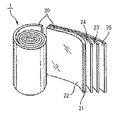
- FIG. 2 is an explanatory diagram illustrating an example of the capacitor element according to this embodiment.
- FIG. 3 is a graph showing values of leakage current during a high temperature load test of the electrolytic capacitors of Examples 13 and 14.
- FIG. 1 is a schematic cross-sectional view showing an example of an electrolytic capacitor according to this embodiment.
- FIG. 2 is an explanatory diagram illustrating an example of the capacitor element according to this embodiment.
- FIG. 3 is a graph showing values of leakage current during a high temperature load test of the electrolytic capacitors of Examples 13 and 14.
- FIG. 1 is a cross-sectional view schematically showing the overall configuration of an electrolytic capacitor according to this embodiment
- FIG. 2 is an explanatory diagram of a capacitor element.
- the capacitor element 1 is arranged inside a bottomed cylindrical exterior case 4 made of metal such as aluminum.
- the elastic sealing member 3 is fixed.
- Capacitor element 1 includes anode foil 20 having sintered aluminum powder 22 formed on the surface of core material (base material) 21 , cathode foil 23 , and a second electrode foil 23 disposed between anode foil 20 and cathode foil 23 .
- the wound capacitor element 1 is configured by winding one separator 24 and a second separator 25, and is sealed in an exterior case 4 after being impregnated with an electrolytic solution.
- Reference numeral 2 denotes lead wires attached to the anode foil 20 and the cathode foil 23, respectively.
- the sintered body 22 is formed on both sides or one side of the base material 21 .
- the sintered body 22 may also be formed on the cathode foil 23 (not shown).
- the base material 21 does not necessarily have to be included, and the anode foil 20 or the cathode foil 23 may be composed only of the sintered body 22 of aluminum powder.
- the present embodiment since the electrode foil has a surface area larger than the pit area of conventional etching foil, a large capacitance can be realized.
- the present embodiment has a structure in which a sintered body is wound in a foil shape, so that the distance between the anode and the cathode current collector is large. As it becomes closer, the resistance component through the electrolytic solution becomes smaller, and the capacitance at high frequencies (about 10 kHz) is excellent.
- the present embodiment is superior in capacitance at high frequencies (about 10 kHz) to electrolytic capacitors using foils to which fine aluminum powder is adhered (for example, Patent Documents 2 and 3).
- the sintered body 22 of powder refers to a sintered body composed of sintered grains of powder.
- the sintered grains mean sintered particles (referred to as “sintered grains” in the present application) obtained by sintering powder particles (referred to as “powder grains” in the present application).
- the aluminum powder sintered body 22 according to the present embodiment is composed of sintered grains of powder made of at least one of aluminum and an aluminum alloy.
- the aluminum and the aluminum in the aluminum alloy preferably have an aluminum purity of 99.8% by weight or more from the viewpoint of preventing problems caused by impurities. More preferably, the purity is 99.99% by weight or more.
- An alloy containing one or more of elements such as vanadium (V), gallium (Ga), nickel (Ni), boron (B) and zirconium (Zr) can be used.
- the content of each of these elements is preferably 100 ppm by weight or less, particularly 50 ppm by weight or less.
- the sintered body 22 is obtained by sintering sintered particles of powder made of at least one of aluminum and aluminum alloy while maintaining gaps between them. That is, each sintered grain is connected to each other while maintaining voids, and has a three-dimensional network structure.
- the porosity in this case can be appropriately set within a range of usually 10% or more depending on the desired capacitance and the like.
- the porosity can be controlled by, for example, the particle size of the starting material aluminum or aluminum alloy powder, the composition of the paste composition (resin binder) containing the powder, and the like.
- the shape of the sintered body 22 is not particularly limited, but in the case of the structure including the base material 21, it is generally preferable that the average thickness of one side is 5 ⁇ m or more and 100 ⁇ m or less, particularly 5 ⁇ m or more and 60 ⁇ m or less. .
- the average thickness can be calculated by a weight method.
- the average particle size of the sintered grains is preferably 80 ⁇ m or less. If the average particle size is more than 80 ⁇ m, the desired capacitance may not be obtained.
- the average particle size of the sintered grains is preferably 1 ⁇ m or more. If the average particle size is less than 1 ⁇ m, the desired withstand voltage may not be obtained.
- a smaller average particle size is more advantageous for increasing the surface area. may decrease. From the viewpoint of preventing such a decrease in capacitance, it is more preferable to set the average particle size to 2.5 ⁇ m or more. In particular, from the viewpoint of improving the capacitance characteristics around 10 kHz, the average particle size is preferably 2.5 ⁇ m or more and 6 ⁇ m or less.
- the substrate 21 is not particularly limited, but aluminum foil can be preferably used.
- the substrate 21 can be used without etching, but may be etched if necessary.
- aluminum foil as the substrate 21 aluminum or an aluminum alloy having the same composition as the powder of aluminum or aluminum alloy can be used. In particular, in order to suppress an increase in leakage current under high-temperature load, it is more preferable that the purity of aluminum is 99.99% by weight or more.
- the thickness of the aluminum foil as the base material 21 is not particularly limited, it is preferably in the range of 5 ⁇ m to 100 ⁇ m, particularly 5 ⁇ m to 60 ⁇ m.
- the method of forming the sintered body 22 on the base material 21 to form the electrode foil 20 (23) is as follows. i.e. 1. 1. A first step of forming a coating on the base material 21 from a composition containing powder of at least one of aluminum and aluminum alloy; A second step of sintering the film at a temperature of 560° C. or higher and 660° C. or lower is included.
- a film made of a composition containing powder of at least one of aluminum and aluminum alloy is formed on the substrate 21 .
- the composition (ingredients) of aluminum or an aluminum alloy those listed above can be used.
- the particle shape of the powder, that is, powder grains, is not particularly limited, and any of spherical, irregular, scale-like and the like can be suitably used, but spherical powder grains can be particularly suitably used.
- the powder, that is, the average particle size of powder grains is preferably 80 ⁇ m or less. If the average particle size is more than 80 ⁇ m, the desired capacitance may not be obtained.
- the powder, ie, the average particle size of powder grains is preferably 1 ⁇ m or more.
- the average particle size is less than 1 ⁇ m, the desired withstand voltage may not be obtained.
- a smaller average particle size is more advantageous for increasing the surface area. may decrease.
- the average particle size is preferably 2.5 ⁇ m or more and 6 ⁇ m or less.
- the particle size of the powder grains does not change significantly even after sintering in the second step, and by adjusting the average particle size of the powder grains, the average particle size of the sintered grains is adjusted to the same extent. be able to.
- the composition may contain resin binders, solvents, sintering aids, surfactants, etc., if necessary. Any of these can be known or commercially available.
- a paste composition containing at least one of a resin binder and a solvent. Thereby, a film can be efficiently formed.
- solvents can be used.
- organic solvents such as ethanol, toluene, ketones and esters can be used.
- the film is sintered at a temperature of 560°C or higher and 660°C or lower.
- the sintering temperature is 560° C. or higher and 660° C. or lower, preferably 560° C. or higher and lower than 660° C., more preferably 570° C. or higher and 659° C. or lower.
- the sintering time varies depending on the sintering temperature and the like, but can be appropriately determined within a range of about 5 to 24 hours.
- the sintering atmosphere is not particularly limited, and may be, for example, a vacuum atmosphere, an inert gas atmosphere, an oxidizing gas atmosphere (atmosphere), a reducing atmosphere, or the like. is preferred. Also, the pressure conditions may be normal pressure, reduced pressure or increased pressure.
- the temperature range is from 100° C. to 600° C. for a holding time of 5 hours or longer.
- Heat treatment is preferably performed.
- the heat treatment atmosphere is not particularly limited, and may be, for example, a vacuum atmosphere, an inert gas atmosphere, or an oxidizing gas atmosphere.
- the pressure condition may be normal pressure, reduced pressure or increased pressure.
- the electrode material of the present invention can be obtained in the second step. This can be used as the electrode (electrode foil 20 (23)) for the aluminum electrolytic capacitor 10 as it is without etching, but may be etched if necessary.
- the electrolyte preferably has a specific resistance of 1500 ⁇ cm or less.
- the ratio of the capacitance at 10 kHz to the capacitance at 120 Hz becomes closer to 1 than in the conventional case, and good capacitance characteristics can be obtained over a wide frequency range.
- the electrolyte preferably has a specific resistance of 100 ⁇ cm or more.
- the electrolytic solution of the present invention contains at least an electrolyte and a solvent. Additives described later may also be added.
- a solvent for dissolving the electrolyte and additives preferably an organic solvent can be used alone, or a water-organic solvent system, ie a mixture of an organic solvent and water, can be used. .
- protic solvents or aprotic solvents can be used alone or in combination of two or more. If necessary, one or more protic solvents and one or more aprotic solvents may be used in any combination.
- Suitable protic solvents include, for example, alcohol compounds. Specific examples of alcohol compounds that can be advantageously used here include, but are not limited to, monohydric alcohols such as methyl alcohol, ethyl alcohol, propyl alcohol, and butyl alcohol, ethylene glycol, and diethylene glycol listed below.
- dihydric alcohols such as triethylene glycol, polyethylene glycol, propylene glycol, dipropylene glycol, tripropylene glycol, polypropylene glycol, 1,4-butanediol and 1,3-butanediol, trihydric alcohols such as glycerin , or derivatives thereof.
- Suitable aprotic solvents include, but are not limited to, lactone compounds such as ⁇ -butyrolactone, ⁇ -valerolactone and ⁇ -valerolactone listed below, sulfolane, methylsulfolane, dimethylsulfolane, propylene carbonate, Ethylene carbonate, isobutylene carbonate, methylpyrrolidone, imidazolidinone, pyrrolidine, pyrrolidinone, methylpyrrolidinone, tetrahydrofuran, acetonitrile, N-methylformamide, N,N-dimethylformamide, nitrobenzene, their derivatives and other intramolecularly polarizable compounds. can be mentioned.
- a water-organic solvent system solvent can be used instead of using the organic solvent alone as described above.
- a water-organic solvent By using such a water-organic solvent, the freezing point of the solvent is lowered, thereby improving the resistivity characteristics of the electrolyte at low temperatures and reducing the difference in resistivity between low and room temperatures. It is possible to realize good low-temperature characteristics indicated by
- this proton-based organic solvent has a boiling point of 198°C and a melting point of about -13°C.
- the temperature range required for capacitors is generally -40°C to 105°C. Coagulation may degrade electrical properties.
- the electrolytic solution according to the present embodiment uses an organic solvent with excellent temperature characteristics alone or in a mixture of a plurality of kinds.
- a solvent-based solvent By using a solvent-based solvent, the freezing point of the solvent can be lowered to ensure electrical properties at low temperatures.
- this water-organic solvent-based electrolytic solution has a very high electrolyte dissolving power and ion mobility, it can realize a much lower specific resistance than an electrolytic solution containing only an organic solvent.
- the properties of the solvent are improved, so the electrolytic solution has an epoch-making property that the difference in resistivity between low temperature and room temperature is small. Therefore, the electrolytic capacitor 10 using such an electrolytic solution can of course have good temperature characteristics reflecting the characteristics of the electrolytic solution.
- organic acids preferably carboxylic acids or salts thereof, boron complexes of dicarboxylic acids or hydroxycarboxylic acids or salts thereof, and inorganic acids or salts thereof are used.
- These electrolyte components may be used alone, or two or more electrolyte components may be used in any combination.
- an inorganic acid or a salt thereof is used in combination with a carboxylic acid or a salt thereof, a boron complex of a dicarboxylic acid or a hydroxycarboxylic acid, or a salt thereof, as an electrolyte component, the freezing point of the electrolyte solution can be lowered, thereby improving the low-temperature properties of the electrolyte solution. can contribute to further improvement.
- carboxylic acids that can be used as electrolyte components include, but are not limited to, formic acid, acetic acid, propionic acid, butyric acid, p-nitrobenzoic acid, salicylic acid, benzoic acid, methylbenzoic acid, ethylbenzoic acid.
- Carboxylic acids containing hydroxyl groups and the like, such as citric acid can also be used.
- the dicarboxylic acid or hydroxycarboxylic acid in the boron complex of dicarboxylic acid or hydroxycarboxylic acid that can also be used as an electrolytic solution component is not limited to those listed below, but borodioxalic acid, borodimalonic acid, borodimalonic acid, acid, borodidipic acid, borodimaleic acid, borodiglycolic acid, borodilactic acid, borodimalic acid, boroditartaric acid, borodicitric acid, borodisalicylic acid, borodiphthalic acid, borodi(2-hydroxy)isobutyric acid, borodimandelic acid, borodi(3-hydroxy) Propionic acid and the like can be mentioned.
- inorganic acids that can also be used as electrolyte components include phosphoric acid, phosphorous acid, hypophosphorous acid, alkyl phosphoric acid, phosphomolybdic acid, boric acid, and sulfamine. Acids and the like can be mentioned. Derivatives of such inorganic acids may also be used, if desired.
- salts of the carboxylic acids or inorganic acids described above can be used as the salts of the carboxylic acids or inorganic acids described above.
- suitable salts include, but are not limited to, sodium salts, potassium salts, ammonium salts, alkylammonium salts, and one or more selected from amine salts and amidine salts listed below.
- Amidine salts include 1,3-dimethylimidazolinium, 1,3-diethylimidazolinium, 1,2,3-trimethylimidazolinium, 1,2,3,4-tetramethylimidazolinium, 1,3 -dimethyl-2-ethylimidazolinium, 1,2-dimethyl-3-ethylimidazolinium, 1,2-dimethyl-3-ethylimidazolinium, 1,2,3-triethylimidazolinium, 1,2 , 3,4-tetraethylimidazolinium.
- Examples include tetraalkylammonium salts, imidazolium salts, and the like.
- an inorganic acid or a salt thereof as an electrolyte component can be expected to lower the freezing point of the electrolyte, contributing to the improvement of the low-temperature characteristics of the electrolyte.
- an inorganic acid or a salt thereof if a nitro compound is used as an additive, there is a hydrogen gas absorption effect derived from the nitro compound.
- an electrolyte component such as an inorganic acid or a salt thereof in combination with an electrolyte component such as the carboxylic acid or a salt thereof
- the carboxylic acid or a salt thereof can be used alone.
- the life of the electrolytic capacitor 10 is remarkably extended.
- the amount of electrolyte contained in the electrolytic solution according to this embodiment can be appropriately determined according to conditions such as the properties required for the electrolytic solution, the type of solvent used, and the type of electrolyte used.
- a carboxylic acid or a salt thereof when used as an electrolyte, its amount should be about 3 to 30% by mass of the total weight of the electrolyte. If the amount of the electrolyte is less than 3% by mass, the desired conductivity cannot be sufficiently ensured, and if it exceeds 30% by mass, the effect is saturated and the electrolyte becomes difficult to dissolve in the solvent.
- the amount should be about 0.1 to 15% by mass of the total amount of the electrolyte. If the amount of the electrolyte is less than 0.1% by mass, the desired electrical conductivity cannot be sufficiently secured, and if it exceeds 15% by mass, the effect is saturated and the electrolyte becomes difficult to dissolve in the solvent. Also when a carboxylic acid or its salt and an inorganic acid or its salt are used in combination, they can be used within the above range.
- the electrolyte solution according to the present embodiment includes (1) a chelate compound, (2) sugars and derivatives thereof, (3) gluconic acid and (or) gluconolactone, (4) the nitro compound, (5) a polymer Additives such as chemical compounds are preferably added as required. These additives may be used alone, or two or more additives may be used in any combination. Each additive will be described below.
- Chelate compound Chelate compounds such as ethylenediaminetetraacetic acid (EDTA), trans-1,2-diaminocyclohexane-N,N,N',N',N'-tetraacetic acid-hydrate (CyDTA), dihydroxy ethylglycine (DHEG), ethylenediaminetetrakis(methylenephosphonic acid) (EDTPO), diethylenetriamine-N,N,N',N'',N''-pentaacetic acid (DTPA), diaminopropanoltetraacetic acid (DPTA-OH), Ethylenediaminediacetic acid (EDDA), ethylenediamine-N,N'-bis(methylenephosphonic acid) hemihydrate (EDDPO), glycol etherdiaminetetraacetic acid (GEDTA), hydroxyethylethylenediaminetriacetic acid (EDTA-OH), etc.
- EDTA ethylenediaminetetraacetic acid
- the chelate compound in the range of 0.01 to 3% by mass.
- Such a chelate compound extends the life of the capacitor 10 by suppressing the hydration reaction of the aluminum (Al) electrode foil of the low impedance capacitor, and improves the low temperature characteristics of the electrolytic capacitor 10 (because the solvent has a composition close to the non-freezing state, The change in impedance between room temperature and low temperature is small) and corrosion resistance can be improved.
- sugars and derivatives thereof examples include monosaccharides such as glucose, fructose, xylose, galactose, ribose, mannose, arabinose, lyxose, allose, altose, gulose, idostallose, derivatives thereof, and erythritol.
- sugar alcohols such as mannitol, disaccharides such as maltose, sucrose, lactose, cellobiose, sucrose, agarobiose and their derivatives, trisaccharides such as maltotriose and their derivatives, starch, glycogen, alginic acid, agar, polysaccharides such as mannan, derivatives thereof, and the like. It is generally preferable to add sugars and derivatives thereof in the range of 0.01 to 5% by mass.
- Such sugars and their derivatives are useful for extending the life of the capacitor 10 by suppressing the hydration reaction of the electrode foils of the low-impedance capacitor, suppressing the decomposition and activation of electrolytes such as carboxylic acids by adding sugars and their derivatives, and electrolysis. Effects such as improvement of the low-temperature characteristics of the capacitor 10 (because the solvent has a composition close to the non-freezing state, the change in impedance between room temperature and low temperature becomes small) can be brought about.
- the electrolytic solution according to the present embodiment can contain gluconic acid, gluconolactone, and the like alone or in combination, if necessary.
- Additives of this type are generally preferably added in the range of 0.01 to 5% by weight.
- the electrolytic solution according to the present embodiment may optionally contain nitrophenol such as p-nitrophenol, nitrobenzoic acid such as p-nitrobenzoic acid, dinitrobenzoic acid, nitroacetophenone such as p-nitro. It may contain at least one nitro compound selected from the group of compounds such as acetophenone, nitroanisole, nitrobenzyl alcohol.
- the nitro compound is preferably added in an amount of 0.01 to 5% by mass based on the total amount of the electrolytic solution. If the amount of the nitro compound added is less than 0.01% by mass, the desired effect can hardly be obtained. In some cases, it is conceivable that other characteristics may be adversely affected.
- Polymer compound examples include water-soluble silicone, polyacrylic acid and its derivatives, polymethacrylic acid and its derivatives, polyacrylamide and its derivatives, polyglutamic acid and its derivatives, polyglycerin and its derivatives, polyethylene glycol and its derivatives. Derivatives such as polypropylene glycol and its derivatives, polyvinyl alcohol and its derivatives can be used. Such a polymer compound can bring about effects according to the action of each polymer compound, such as improvement of the withstand voltage characteristics of the electrolytic capacitor 10 and extension of the life of the electrolytic capacitor 10 .
- a wide range of molecular weight polymer compounds can be used, from relatively low molecular weight (oligomers) to high molecular weight, depending on the action of each polymer compound, solubility and dispersibility in solvents, and desired effects. can.
- the electrolytic solution according to the present embodiment may further contain additives commonly used in the field of aluminum electrolytic capacitors or other electrolytic capacitors, in addition to the additives described above.
- Suitable additives include, for example, silane coupling agents, polymer electrolytes, colloidal silica, and the like.
- the separators 24 and 25 are not particularly limited, they are preferably made of naturally occurring cellulose materials such as manila hemp or vegetable pulp, and the raw material pulp is subjected to a dust removal process, a washing process, and a beating process. Those manufactured through a process, a papermaking process, etc. can be advantageously used. Also usable are woven fabrics, non-woven fabrics, sheets and films made from synthetic fibers such as rayon, nylon, polyester, polyvinyl compounds, aramid, acryl, and polyurethane. In addition, it is also possible to use a mixed product of natural fibers and synthetic fibers, a blended product, and the like.
- non-heat-treated aluminum with a purity of 99.0% or higher e.g., non-heat-treated material of aluminum 1100
- heat-treated aluminum with a purity of 99.0% or higher e.g., H22 material of 1000 series aluminum
- manganese (Mn) and/or magnesium (Mg) containing aluminum alloy refining material for example, aluminum alloy 3003 O material, 3000 series aluminum alloy H22 material, aluminum alloy 3004 O material
- the sealing member 3 used in the electrolytic capacitor 10 of the present embodiment is made of a material having high hardness, moderate rubber elasticity, impermeability to the electrolyte, and excellent airtightness as the sealing member 3. As long as it can be formed from various conventional materials. Suitable sealing member 3 materials include, for example, elastic rubbers such as natural rubber (NR), styrene-butadiene rubber (SBR), ethylene-propylene terpolymer (EPT), and isobutylene-isoprene rubber (IIR). . In particular, isobutylene-isoprene rubber (IIR) is suitable because it has high airtightness and does not permeate the electrolytic solution as vapor.
- NR natural rubber
- SBR styrene-butadiene rubber
- EPT ethylene-propylene terpolymer
- IIR isobutylene-isoprene rubber
- IIR is suitable because it has high airtightness and does not permeate the electrolytic
- IIRs having better heat resistance such as sulfur vulcanization, quinoid vulcanization, resin vulcanization, peroxide vulcanization, and the like.
- high-hardness rubber As for the hardness, by using a sealing rubber having a hardness of 80 (IRHD/M) or more in rubber hardness measurement (30-second value) with an IRHD hardness tester, mechanical stress is less likely to be applied, and an increase in leakage current is suppressed. can do.
- a hybrid material in which an airtight and sufficiently high-strength resin material plate (for example, a fluororesin plate such as a PTFE plate) and elastic rubber are adhered together is also advantageous. can be used for
- the lead wire 2 used as an external connection terminal or an external electrode terminal and inserted into the lead wire through-hole of the sealing body 3 is made of iron, copper, tin, lead, silver, gold, zinc, bismuth, tungsten, nickel, It can be formed from various metallic materials such as titanium and chromium.
- the lead wire 2 is advantageous to form the lead wire 2 from a highly conductive metallic material such as copper, silver, iron, gold, etc., especially copper wire or silver wire.
- Example 1 an aluminum electrolytic capacitor with a wound structure was produced according to the following procedure.
- An anode foil of an aluminum powder sintered body was produced by the manufacturing method (first to third steps) disclosed above, and then a lead wire for leading out an electrode was attached. Also, another aluminum foil was electrochemically etched to prepare a cathode foil, and then a lead wire for leading out the electrode was attached. Subsequently, a capacitor element was produced by winding a separator (separating paper) between the anode foil and the cathode foil.
- an electrolytic solution was prepared by sequentially adding a solvent component and an electrolyte component to a fixed container and then stirring and dissolving them.
- the capacitor element was impregnated with the electrolytic solution produced by the above preparation method, it was housed in an aluminum case with a bottom so that the lead wire for leading out the electrode protruded from the case, and the opening of this case was sealed with an elastic sealing member.
- a post-aging treatment was performed to produce an electrolytic capacitor having a wound structure.
- Comparative example 1 In Comparative Example 1, after an aluminum foil was electrochemically etched, an oxide film was formed on the surface by anodizing, and this was used as an anode foil. Other electrolytic capacitor manufacturing methods were the same as those described in Example 1 above.
- Example 1 In both Example 1 and Comparative Example 1, samples with a foil withstand voltage equivalent to 400 WV in capacitor withstand voltage were produced.
- Example 1 the capacitances of the electrolytic capacitors produced in Example 1 and Comparative Example 1 were measured at 25°C at frequencies of 120 Hz and 10 kHz, and the measured values shown in Table 1 below were obtained.
- Examples 2-12 Next, the relationship between the specific resistance of the electrolytic solution and the capacitance of the capacitor is compared for capacitors manufactured by the same method as in Example 1 at average powder particle sizes of 2.5 ⁇ m and 6 ⁇ m.
- the electrolytic capacitors of Examples 2 to 12 were prepared by repeating the same method as in Example 1, and the electrolytic solution was prepared using the same components as in Example 1, and the specific resistance was 100 ⁇ cm by adjusting the composition. , 30° C. to 2000 ⁇ cm, and 30° C., respectively. Samples with an average powder particle diameter of 2.5 ⁇ m and a capacitor with an average powder particle diameter of 6 ⁇ m were prepared to have a withstand voltage of 400 WV and a foil withstand voltage of 450 WV, respectively.
- Comparative Examples 2-12 The same method as in Comparative Example 1 was repeated as the method for producing capacitors of etched aluminum foil used in Comparative Examples 2 to 12, and the method for producing the electrolytic solution was the same as in Examples 2 to 12 above. As in Examples 2 to 12, samples with a capacitor withstand voltage of 400 WV and 450 WV were produced.
- Tables 2 and 3 list the capacitance at 120 Hz and 10 kHz.
- a typical use of capacitors is for smoothing the primary side of switching power supplies.
- MOS-FETs that repeat switching at a frequency of around 10 kHz in the latter stage of the circuit It also has the role of absorbing current noise from elements such as This noise is called EMI, and since it adversely affects other electrical equipment through commercial power lines, it is regulated by the EMC Directive (89/336/EEC). Increasing the capacitance near 10 kHz is important because it contributes to this noise reduction.
- the capacitance ratio at 120 Hz and 10 kHz shown in Tables 2 and 3 when the specific resistance of the electrolyte is 100 ⁇ cm to 1500 ⁇ cm, the aluminum powder sintered foil has a higher value than the etched foil. showing. At 2000 ⁇ cm, the sintered powder foil shows a lower value than the etched foil. It is considered that this is because particles are aggregated rather than pits, and the path length to the depths of the pits is long, so that when an electrolytic solution with a high specific resistance is used, it becomes difficult to obtain capacitance at high frequencies.
- an aluminum electrolytic capacitor if a foil of a sintered aluminum powder is combined with an electrolytic solution having a specific resistance of 1500 ⁇ cm or less, a 10 kHz capacitance against a 120 Hz capacitance can be obtained more easily than the conventionally used aluminum etched foil.
- Example 13 the relationship between the purity of the aluminum substrate and the life of the capacitor is compared.
- the electrolytic capacitor of Example 13 was produced using an aluminum powder sintered foil whose base material had an aluminum purity of 99.99% by weight or more and whose powder had an aluminum purity of 99.99% by weight or more, For other capacitor fabrication methods, the method described in Example 1 was repeated. Further, in the electrolytic capacitor of Example 14, aluminum powder sintered in which the aluminum purity of the base material is 99.8% by weight or more and less than 99.95% by weight, and the aluminum purity of the powder is 99.99% by weight or more A body foil was used for fabrication, and the method described in Example 1 was repeated for other capacitor fabrication methods.
- FIG. 3 shows the value of the leakage current of the electrolytic capacitor during the high temperature load test.
- the leakage current was suppressed to less than 12 ⁇ A in all the capacitors according to the examples, but especially the capacitor with a base material purity of 99.99% by weight or more (Example 13) tends to increase the leakage current after 3000 hours. is not observed, and the increase in leakage current is suppressed.
- An increase in leakage current leads to an increase in the amount of gas generated inside the capacitor, and the internal pressure gradually rises, increasing the risk of early valve actuation.
- the aluminum purity of the base material is 99.99% by weight or more. Also, for the aluminum powder that is electrically connected to the base material, it is clear that the purity of aluminum is preferably 99.99% by weight or more for the same reason.
- the "average particle size (D50)" means the particle size at 50% of the integrated value in the volume-based particle size distribution determined by the laser diffraction/scattering method.
Landscapes
- Engineering & Computer Science (AREA)
- Power Engineering (AREA)
- Microelectronics & Electronic Packaging (AREA)
- Chemical & Material Sciences (AREA)
- Materials Engineering (AREA)
- Chemical Kinetics & Catalysis (AREA)
- Electrochemistry (AREA)
- Fixed Capacitors And Capacitor Manufacturing Machines (AREA)
Abstract
電極材のエッチング処理が不要であり、またエッチングのみにより表面積を増大させた従来の電極箔を用いた電解コンデンサよりも高静電容量を実現できる電解コンデンサを提供することを課題とする。 解決手段として、本発明に係る電解コンデンサ(10)は、陽極箔(20)と、陰極箔(23)と、前記陽極箔(20)と前記陰極箔(23)との間に介在したセパレータ(24)、(25)を有するコンデンサ素子(1)と、前記コンデンサ素子(1)に含浸された電解液と、を備えた電解コンデンサ(10)であって、前記陽極箔(20)もしくは前記陰極箔(23)は、アルミニウムおよびアルミニウム合金の少なくとも1種からなる粉末の焼結粒で構成された焼結体を有していることを特徴とする。
Description
本発明は電解コンデンサに関する。
電解コンデンサは、小型、大容量かつ安価という特徴を有し、電子機器、電気機器、車両搭載機器などの重要な構成部品の1つとして広く用いられている。
従来の電解コンデンサ、例えば最も広く普及しているアルミニウム電解コンデンサは、高純度アルミニウム箔を電気化学的にエッチングしてその表面積を増加させた後、そのアルミニウム箔の表面に陽極酸化によって皮膜を形成した陽極箔と、表面をエッチングした陰極箔を使用することによって製造することができる。次いで、得られた陽極箔と陰極箔とを対向して配置し、さらにそれらの箔の間にセパレータを介在させて巻回した構造の素子となし、この構造の素子に電解液を含浸する。電解液含浸後の素子をケースに収容し、弾性封口体で密封して電解コンデンサが完成する。
電解コンデンサの高容量化は搭載機器の小型化に直結する重要な市場要求であり、エッチング倍率の拡大による高容量化が図られてきた。しかしエッチングによる表面積増大には理論的限界があり、年々高まる高容量化要求を満たせなくなりつつある。また、エッチング処理で使用される硫酸、燐酸、硝酸等を含有する塩酸による環境負荷を低減させるためにも、エッチング箔に代わる表面積増大方法が望まれる。
ここで、エッチング箔に代わる表面積増大方法として、金属焼結体を陽極としたコンデンサが従来から提案されている(特許文献1:実開昭59-140430号公報)。
しかし、このような形状のコンデンサは陽極から陰極集電体までの距離が長いため、電解液を介した抵抗成分が大きくなり、高周波における静電容量が低下するといった欠点があった。
他の表面積増大方法として、電極箔表面に微細なアルミニウム粉末を付着させた箔を用いたことを特徴とするアルミニウム電解コンデンサが提案されている(特許文献2:特開平2-267916号公報、および特許文献3:特開2006-108159号公報)。
しかしながら、これらの文献で開示されている電極箔はアルミニウム粉末の粒子径が小さいため、陽極酸化皮膜を形成する際に焼結粒間の隙間が埋まり静電容量が低下してしまうおそれがある事、また、比較的高い粘度と比抵抗を有する中高圧コンデンサ用の電解液を用いた場合には、高周波における静電容量が低下するといった欠点があった。
本発明は、上記した高容量化要求および環境負荷軽減に鑑みてなされたものであって、電極材のエッチング処理が不要であり、またエッチングのみにより表面積を増大させた従来の電極箔を用いた電解コンデンサよりも高静電容量を実現できる電解コンデンサを提供することを目的とする。
本発明に係る電解コンデンサは、陽極箔と、陰極箔と、前記陽極箔と前記陰極箔との間に介在したセパレータを有するコンデンサ素子と、前記コンデンサ素子に含浸された電解液と、を備えた電解コンデンサであって、前記陽極箔もしくは前記陰極箔は、アルミニウムおよびアルミニウム合金の少なくとも1種からなる粉末の焼結粒で構成された焼結体を有していることを特徴とする。
前記陽極箔もしくは前記陰極箔は、前記焼結体と、前記焼結体を支持する基材とからなると好適である。また、前記電解液の比抵抗が1500Ω・cm以下であり、前記粉末または前記焼結粒の平均粒子径(D50)が6μm以下であると好適である。
また、前記電解液は、有機溶媒からなる溶媒、もしくは水と有機溶媒との混合物からなる溶媒と、有機酸または有機酸塩、無機酸または無機酸塩、および有機酸もしくは有機酸塩と無機酸もしくは無機酸塩との混合物からなる群から選ばれる少なくとも1種類の電解質と、を含んでいると好適である。
本発明の電解コンデンサによれば、電極箔は従来のエッチング箔がもつピット面積以上の表面積のため、大きな静電容量を実現することができる。また、電極箔のエッチング処理が必ずしも必要でなくなる結果、環境負荷を低減させることができる。
以下、本発明の好適な実施の形態について説明するが、本発明は、これらの形態のみに限定されるものではない。
図1に本実施形態に係る電解コンデンサの全体構成の概略を示す断面図、図2はコンデンサ素子の説明図である。
電解コンデンサ10は、アルミニウム等の金属で形成された有底筒状の外装ケース4の内部にコンデンサ素子1が配置され、外装ケース4の開口部が弾性封口体3で密封され、開口縁をかしめることにより(カール14)弾性封口体3を固定して構成されている。
図1に本実施形態に係る電解コンデンサの全体構成の概略を示す断面図、図2はコンデンサ素子の説明図である。
電解コンデンサ10は、アルミニウム等の金属で形成された有底筒状の外装ケース4の内部にコンデンサ素子1が配置され、外装ケース4の開口部が弾性封口体3で密封され、開口縁をかしめることにより(カール14)弾性封口体3を固定して構成されている。
コンデンサ素子1は、芯材(基材)21の表面にアルミニウム粉末の焼結体22を形成した陽極箔20と、陰極箔23と、陽極箔20と陰極箔23との間に配置された第一のセパレータ24と、第二のセパレータ25とが巻回されて構成された巻回型コンデンサ素子1であって、これに電解液を含浸したのち外装ケース4内に封口される。なお、符号2は陽極箔20と陰極箔23のそれぞれに取り付けたリード線である。
焼結体22は、基材21の両面もしくは片面に形成される。また、焼結体22は陰極箔23にも形成してもよい(図示せず)。
なお、基材21は必ずしも含まれる必要はなく、アルミニウム粉末の焼結体22のみで陽極箔20、もしくは陰極箔23を構成しても良い。
焼結体22は、基材21の両面もしくは片面に形成される。また、焼結体22は陰極箔23にも形成してもよい(図示せず)。
なお、基材21は必ずしも含まれる必要はなく、アルミニウム粉末の焼結体22のみで陽極箔20、もしくは陰極箔23を構成しても良い。
本実施形態によれば、電極箔は従来のエッチング箔がもつピット面積以上の表面積のため、大きな静電容量を実現することができる。また、従来提案されていたアルミ焼結体コンデンサ(例えば特許文献1)に対して、本実施形態は焼結体を箔状として巻回した構造のため、陽極と陰極集電体との距離が近くなる事で電解液を介した抵抗成分が小さくなり、高周波(10kHz程度)における静電容量に優れる。また、微細なアルミニウム粉末を付着させた箔を用いた電解コンデンサ(例えば特許文献2または3)に対しても、本実施形態は高周波(10kHz程度)における静電容量に優れる。
ここで、粉末の焼結体22とは、粉末の焼結粒で構成された焼結体をいう。この焼結粒とは、粉末の粒子(本願では「粉末粒」と表記する)が焼結した焼結粒子(本願では「焼結粒」と表記する)を意味する。
本実施形態に係るアルミニウム粉末の焼結体22は、アルミニウム及びアルミニウム合金の少なくとも1種からなる粉末の焼結粒で構成される。このアルミニウム、及びアルミニウム合金におけるアルミニウムは、不純物に起因する不具合を防止する観点からアルミニウム純度が99.8重量%以上であることが好ましく、特に高温負荷に対する漏れ電流の増大を抑制するには、アルミニウム純度が99.99重量%以上であることがより好ましい。また、アルミニウム合金の場合は、例えば、珪素(Si)、鉄(Fe)、銅(Cu)、マンガン(Mn)、マグネシウム(Mg)、クロム(Cr)、亜鉛(Zn)、チタン(Ti)、バナジウム(V)、ガリウム(Ga)、ニッケル(Ni)、ホウ素(B)およびジルコニウム(Zr)等の元素の1種又は2種以上を含む合金を用いることができる。この場合、これらの元素の含有量は、それぞれ100重量ppm以下、特に50重量ppm以下とすることが好ましい。
本実施形態に係るアルミニウム粉末の焼結体22は、アルミニウム及びアルミニウム合金の少なくとも1種からなる粉末の焼結粒で構成される。このアルミニウム、及びアルミニウム合金におけるアルミニウムは、不純物に起因する不具合を防止する観点からアルミニウム純度が99.8重量%以上であることが好ましく、特に高温負荷に対する漏れ電流の増大を抑制するには、アルミニウム純度が99.99重量%以上であることがより好ましい。また、アルミニウム合金の場合は、例えば、珪素(Si)、鉄(Fe)、銅(Cu)、マンガン(Mn)、マグネシウム(Mg)、クロム(Cr)、亜鉛(Zn)、チタン(Ti)、バナジウム(V)、ガリウム(Ga)、ニッケル(Ni)、ホウ素(B)およびジルコニウム(Zr)等の元素の1種又は2種以上を含む合金を用いることができる。この場合、これらの元素の含有量は、それぞれ100重量ppm以下、特に50重量ppm以下とすることが好ましい。
焼結体22は、アルミニウム及びアルミニウム合金の少なくとも1種からなる粉末の焼結粒どうしが互いに空隙を維持しながら焼結したものである。すなわち、各焼結粒どうしが空隙を維持しながら繋がり、三次元網目構造を有している。このような多孔質焼結体とすることにより、エッチング処理を施さなくても、所望の静電容量を得ることが可能となる。この場合の気孔率は、通常10%以上の範囲内で所望の静電容量等に応じて適宜設定することができる。また、気孔率は、例えば出発材料のアルミニウム又はアルミニウム合金の粉末の粒径、その粉末を含むペースト組成物の組成(樹脂バインダ)等により制御することができる。
焼結体22の形状は特に制限されないが、基材21を含む構成の場合、一般的には片側の面の平均厚みが5μm以上100μm以下、特に5μm以上60μm以下の箔状であることが好ましい。平均厚みは、重量法により平均値を算出できる。
なお、焼結粒の平均粒子径は80μm以下が好ましい。平均粒子径が80μmより大きいと、所望の静電容量が得られないおそれがある。
焼結粒の平均粒子径は1μm以上が好ましい。平均粒子径が1μmより小さいと、所望の耐電圧が得られないおそれがある。なお、表面積を大きくするうえでは平均粒子径が小さい方が有利だが、平均粒子径を小さくしすぎると、必要に応じて陽極酸化皮膜を形成する際に焼結粒間の隙間が埋まり静電容量が低下してしまうおそれがある。そのような静電容量の低下を防止する観点では、平均粒子径を2.5μm以上にすることがより好ましい。
特に、10kHz付近における静電容量特性を良好にする観点では、平均粒子径が2.5μm以上6μm以下であることが好ましい。
焼結粒の平均粒子径は1μm以上が好ましい。平均粒子径が1μmより小さいと、所望の耐電圧が得られないおそれがある。なお、表面積を大きくするうえでは平均粒子径が小さい方が有利だが、平均粒子径を小さくしすぎると、必要に応じて陽極酸化皮膜を形成する際に焼結粒間の隙間が埋まり静電容量が低下してしまうおそれがある。そのような静電容量の低下を防止する観点では、平均粒子径を2.5μm以上にすることがより好ましい。
特に、10kHz付近における静電容量特性を良好にする観点では、平均粒子径が2.5μm以上6μm以下であることが好ましい。
基材21としては、特に限定されないが、アルミニウム箔を好適に用いることができる。なお、基材21はエッチング処理を施すことなく用いることが可能であるが、必要に応じてエッチング処理を施してもよい。
基材21としてのアルミニウム箔は、上記のアルミニウム又はアルミニウム合金に係る粉末と同様の組成のアルミニウム又はアルミニウム合金を用いることができる。特に高温負荷に対する漏れ電流の増大を抑制するには、アルミニウム純度99.99重量%以上であることがより好ましい。
基材21としてのアルミニウム箔の厚みは、特に限定されないが、5μm以上100μm以下、特に5μm以上60μm以下の範囲内とするのが好ましい。
基材21としてのアルミニウム箔は、上記のアルミニウム又はアルミニウム合金に係る粉末と同様の組成のアルミニウム又はアルミニウム合金を用いることができる。特に高温負荷に対する漏れ電流の増大を抑制するには、アルミニウム純度99.99重量%以上であることがより好ましい。
基材21としてのアルミニウム箔の厚みは、特に限定されないが、5μm以上100μm以下、特に5μm以上60μm以下の範囲内とするのが好ましい。
基材21上に焼結体22を形成し、電極箔20(23)とする方法は次の方法による。すなわち、
1.アルミニウム及びアルミニウム合金の少なくとも1種の粉末を含む組成物からなる皮膜を基材21に形成する第1工程、および
2.前記皮膜を560℃以上660℃以下の温度で焼結する第2工程
を含む。
1.アルミニウム及びアルミニウム合金の少なくとも1種の粉末を含む組成物からなる皮膜を基材21に形成する第1工程、および
2.前記皮膜を560℃以上660℃以下の温度で焼結する第2工程
を含む。
第1工程
第1工程では、アルミニウム及びアルミニウム合金の少なくとも1種の粉末を含む組成物からなる皮膜を基材21に形成する。
アルミニウム又はアルミニウム合金の組成(成分)としては、前記で掲げたものを用いることができる。
前記粉末すなわち粉末粒の粒子形状は、特に限定されず、球状、不定形状、鱗片状等のいずれも好適に使用できるが、球状の粉末粒が特に好適に使用できる。
粉末すなわち粉末粒の平均粒子径は80μm以下が好ましい。平均粒子径が80μmより大きいと、所望の静電容量が得られないおそれがある。
粉末すなわち粉末粒の平均粒子径は1μm以上が好ましい。平均粒子径が1μmより小さいと、所望の耐電圧が得られないおそれがある。なお、表面積を大きくするうえでは平均粒子径が小さい方が有利だが、平均粒子径を小さくしすぎると、必要に応じて陽極酸化皮膜を形成する際に焼結粒間の隙間が埋まり静電容量が低下してしまうおそれがある。そのような静電容量の低下を防止する観点では、平均粒子径を2.5μm以上にすることがより好ましい。
特に、10kHz付近における静電容量特性を良好にする観点では、平均粒子径が2.5μm以上6μm以下であることが好ましい。
なお、粉末粒の粒子径は、第2工程の焼結後も大きく変化することなく、粉末粒の平均粒子径を調整することによって、前述の焼結粒の平均粒子径も同程度に調整することができる。
前記組成物は、必要に応じて樹脂バインダ、溶剤、焼結助剤、界面活性剤等が含まれていても良い。これらはいずれも公知又は市販のものを使用することができる。特に、樹脂バインダおよび溶剤の少なくとも1種を含有させてペースト状組成物として用いることが好ましい。これにより効率よく皮膜を形成することができる。
また、溶媒も公知のものが使用できる。例えば、水のほか、エタノール、トルエン、ケトン類、エステル類等の有機溶剤を使用することができる。
第2工程
第2工程では、前記皮膜を560℃以上660℃以下の温度で焼結する。
焼結温度は、560℃以上660℃以下とし、好ましくは560℃以上660℃未満、より好ましくは570℃以上659℃以下とする。焼結時間は、焼結温度等により異なるが、通常は5~24時間程度の範囲内で適宜決定することができる。
第2工程では、前記皮膜を560℃以上660℃以下の温度で焼結する。
焼結温度は、560℃以上660℃以下とし、好ましくは560℃以上660℃未満、より好ましくは570℃以上659℃以下とする。焼結時間は、焼結温度等により異なるが、通常は5~24時間程度の範囲内で適宜決定することができる。
焼結雰囲気は、特に制限されず、例えば真空雰囲気、不活性ガス雰囲気、酸化性ガス雰囲気(大気)、還元性雰囲気等のいずれであっても良いが、特に真空雰囲気又は還元性雰囲気とすることが好ましい。また、圧力条件についても、常圧、減圧又は加圧のいずれでも良い。
なお、前記組成物中に樹脂バインダ等の有機成分が含有している場合は、第1工程後第2工程に先立って予め100℃以上から600℃以下の温度範囲で保持時間が5時間以上の加熱処理(脱脂処理)を行なうことが好ましい。加熱処理雰囲気は特に限定されず、例えば真空雰囲気、不活性ガス雰囲気又は酸化性ガス雰囲気中のいずれでも良い。また、圧力条件も、常圧、減圧又は加圧のいずれでも良い。
前記の第2工程において、本発明の電極材を得ることができる。これは、エッチング処理を施すことなく、そのままアルミニウム電解コンデンサ10用電極(電極箔20(23))として用いることが可能であるが、必要に応じてエッチング処理を施してもよい。
前記の第2工程において、本発明の電極材を得ることができる。これは、エッチング処理を施すことなく、そのままアルミニウム電解コンデンサ10用電極(電極箔20(23))として用いることが可能であるが、必要に応じてエッチング処理を施してもよい。
第3工程
前記電極材は、必要に応じて第3工程として陽極酸化処理を施すことにより誘電体を形成させることができる。例えば、所定の陽極酸化処理により耐電圧性を備えた誘電体酸化皮膜を形成することで、所望の耐電圧を有する電解コンデンサ10用の陽極箔20とすることができる。
前記電極材は、必要に応じて第3工程として陽極酸化処理を施すことにより誘電体を形成させることができる。例えば、所定の陽極酸化処理により耐電圧性を備えた誘電体酸化皮膜を形成することで、所望の耐電圧を有する電解コンデンサ10用の陽極箔20とすることができる。
次に、電解液について説明する。
本発明では、電解液の比抵抗が1500Ω・cm以下であることが好ましい。これにより、従来に比べて120Hzの静電容量に対する10kHzの静電容量の比が1に近くなり、広い周波数範囲で良好な静電容量特性が得られる。また、所望の耐電圧を確保する観点では、電解液の比抵抗が100Ω・cm以上であることが好ましい。
本発明の電解液は、電解質と、溶媒とを少なくとも含有する。また後記する添加剤を添加してもよい。電解質および添加剤を溶解するための溶媒として、好ましくは、有機溶媒を単独で使用するか、さもなければ、水-有機溶媒系の溶媒、すなわち有機溶媒と水との混合物を使用することができる。
本発明では、電解液の比抵抗が1500Ω・cm以下であることが好ましい。これにより、従来に比べて120Hzの静電容量に対する10kHzの静電容量の比が1に近くなり、広い周波数範囲で良好な静電容量特性が得られる。また、所望の耐電圧を確保する観点では、電解液の比抵抗が100Ω・cm以上であることが好ましい。
本発明の電解液は、電解質と、溶媒とを少なくとも含有する。また後記する添加剤を添加してもよい。電解質および添加剤を溶解するための溶媒として、好ましくは、有機溶媒を単独で使用するか、さもなければ、水-有機溶媒系の溶媒、すなわち有機溶媒と水との混合物を使用することができる。
有機溶媒としては、プロトン系溶媒又は非プロトン系溶媒をそれぞれ単独であるいは2種以上を混合して使用することができる。必要に応じて、プロトン系溶媒の1種以上と非プロトン系溶媒の1種以上を任意に組合せて使用してもよい。適当なプロトン系溶媒として、例えば、アルコール化合物を挙げることができる。ここで有利に使用することのできるアルコール化合物の具体的な例としては、特に限定されないが、以下に列挙する、メチルアルコール、エチルアルコール、プロピルアルコール、ブチルアルコール等の一価アルコール、エチレングリコール、ジエチレングリコール、トリエチレングリコール、ポリエチレングリコール、プロピレングリコール、ジプロピレングリコール、トリプロピレングリコール、ポリプロピレングリコール、1,4-ブタンジオール、1,3-ブタンジオール等の二価アルコール(グリコール)、グリセリン等の三価アルコール、あるいはこれらの誘導体等を挙げることができる。また、適当な非プロトン系溶媒としては、特に限定されないが、以下に列挙する、γ-ブチロラクトン、γ-バレロラクトン、δ-バレロラクトン等のラクトン化合物、スルホラン、メチルスルホラン、ジメチルスルホラン、プロピレンカーボネート、エチレンカーボネート、イソブチレンカーボネート、メチルピロリドン、イミダゾリジノン、ピロリジン、ピロリジノン、メチルピロリジノン、テトラヒドロフラン、アセトニトリル、N-メチルホルムアミド、N,N-ジメチルホルムアミド、ニトロベンゼン、それらの誘導体やその他の分子内分極性化合物を挙げることができる。
本実施形態に関わる電解液では、上記したように有機溶媒の単独使用をする代わりに、水-有機溶媒系の溶媒を使用することもできる。このような水-有機溶媒系の溶媒を使用することで、溶媒の凝固点を低下させ、それにより低温での電解液の比抵抗特性を改善して、低温と常温での比抵抗の差が小さいことで示される良好な低温特性を実現することができる。
さらに詳しく説明すると、有機溶媒としてエチレングリコールを使用した場合を例に挙げると、このプロトン系有機溶媒は沸点が198℃、融点は約-13℃である。コンデンサに要求される温度範囲は、一般的に-40℃~105℃であることから、この溶媒を使用した電解液は、高温では特性に余裕があるが、低温では電解液の粘性の増大や凝固によって電気特性が低下するおそれがある。
本実施形態に関わる電解液は、温度特性の優れた有機溶媒を単独あるいは複数種の混合で使用する一方、凝固点が比較的高い有機溶媒を使用する場合には、水を添加して水-有機溶媒系の溶媒を使用することで、溶媒の凝固点を低下させて低温での電気特性を確保することができる。この水-有機溶媒系の電解液は、電解質の溶解能とイオンの移動度が非常に大きいので、有機溶媒単独の電解液より、遥かに低い比抵抗が実現できる。また低温においては、溶媒の特性が改善されているので、低温と常温での比抵抗の差が小さい、という画期的な特性を有する電解液となる。したがって、このような電解液を使用した電解コンデンサ10は、当然ながら、電解液の特性を反映して、良好な温度特性を有することができる。
電解質としては、有機酸、好ましくはカルボン酸又はその塩や、ジカルボン酸又はヒドロキシカルボン酸のホウ素錯体又はその塩、そして無機酸又はその塩を使用する。これらの電解質成分は、単独で使用してもよく、2種類以上の電解質成分を任意に組合せて使用してもよい。電解質成分として、カルボン酸又はその塩やジカルボン酸又はヒドロキシカルボン酸のホウ素錯体又はその塩に、無機酸またはその塩を併用すると、電解液の凝固点降下が期待でき、そのため電解液の低温特性の更なる向上に寄与することができる。
電解質成分として使用可能なカルボン酸の例としては、以下に列挙するものに限定されないが、蟻酸、酢酸、プロピオン酸、酪酸、p-ニトロ安息香酸、サリチル酸、安息香酸、メチル安息香酸、エチル安息香酸、イソブチル安息香酸、sec-ブチル安息香酸、tert-ブチル安息香酸などに代表されるモノカルボン酸やその誘導体、シュウ酸、マロン酸、コハク酸、グルタル酸、アジピン酸、フマル酸、マレイン酸、フタル酸、アゼライン酸、セバシン酸、カプリル酸、1,6-デカンジカルボン酸、5,6-デカンジカルボン酸、メチルアジピン酸、エチルアジピン酸、イソブチルアジピン酸、sec-ブチルアジピン酸、tert-ブチルアジピン酸などに代表されるジカルボン酸やその誘導体を挙げることができる。また、クエン酸のような、ヒドロキシル基等を含有するカルボン酸も使用可能である。
また、同じく電解液成分として使用可能なジカルボン酸又はヒドロキシカルボン酸のホウ素錯体におけるジカルボン酸またはヒドロキシカルボン酸は、以下に列挙するものに限定されるわけではないけれども、ボロジ蓚酸、ボロジマロン酸、ボロジこはく酸、ボロジアジピン酸、ボロジマレイン酸、ボロジグリコール酸、ボロジ乳酸、ボロジリンゴ酸、ボロジ酒石酸、ボロジクエン酸、ボロジサリチル酸、ボロジフタル酸、ボロジ(2-ヒドロキシ)イソ酪酸、ボロジマンデル酸、ボロジ(3-ヒドロキシ)プロピオン酸などを挙げることができる。
さらに、同じく電解質成分として使用可能な無機酸の例としては、以下に列挙するものに限定されないが、リン酸、亜リン酸、次亜リン酸、アルキルリン酸、リンモリブデン酸、ホウ酸、スルファミン酸などを挙げることができる。また、必要に応じて、このような無機酸の誘導体を使用してもよい。
さらに、上記したカルボン酸または無機酸の塩として、いろいろな一般的に知られた塩を使用することができる。適当な塩の例としては、特に限定されないが、ナトリウム塩、カリウム塩、アンモニウム塩、アルキルアンモニウム塩や以下に列挙する、アミン塩、アミジン塩から選ばれる1種以上であってよい。アミン塩としてはジメチルアミン、ジエチルアミン、トリメチルアミン、トリエチルアミン、エチルジメチルアミン、ジエチルメチルアミン、メタノールアミン、エタノールアミン、ジメタノールアミン、ジエタノールアミン、トリメタノールアミン、トリエタノールアミン、ピロリジン、ピペリジン、ピペラジン、モルホリン、メチルモルホリン、エチルモルホリン、オキサゾリジン、チオモルホリン、チアゾリジンモルホリン、メチルモルホリン、エチルモルホリン、オキサゾリジン、チオモルホリン、チアゾリジンなどの塩が挙げられる。アミジン塩としては1,3-ジメチルイミダゾリニウム、1,3-ジエチルイミダゾリニウム、1,2,3-トリメチルイミダゾリニウム、1,2,3,4-テトラメチルイミダゾリニウム、1,3-ジメチル-2-エチルイミダゾリニウム、1,2-ジメチル-3-エチルイミダゾリニウム、1,2-ジメチル-3-エチルイミダゾリニウム、1,2,3-トリエチルイミダゾリニウム、1,2,3,4-テトラエチルイミダゾリニウムなどの塩が挙げられる。テトラアルキルアンモニウム塩、イミダゾリウム塩などを挙げることができる。
さらに加えて、電解質成分として無機酸またはその塩を使用すると、電解液の凝固点降下を期待でき、電解液の低温特性の改良に寄与することができる。また、無機酸またはその塩を使用するときに、添加剤としてニトロ化合物を使用した場合には 、ニトロ化合物に由来する水素ガス吸収効果がある。
また、このような無機酸またはその塩のような電解質成分を前記したカルボン酸またはその塩のような電解質成分に組合せて使用することにより、カルボン酸またはその塩を単独で使用した場合に比較して、電解コンデンサ10の寿命が顕著に伸びる。
本実施形態に関わる電解液において、それに含まれる電解質の量は、電解液に要求される特性、使用する溶媒の種類、使用する電解質の種類等の条件に応じて適宜決定することができる。一般的に言って、例えばカルボン酸又はその塩を電解質として使用する場合に、その量は 、電解液の全重量の3~30質量%程度であるのがよい。かかる電解質の量が3質量%に満たない場合には所望の電導度を充分確保することができず、30質量%を超えると効果が飽和してくる上に、溶媒に溶けにくくなる。
無機酸またはその塩を電解質として使用する場合に、その量は、電解液の全量の0.1~15質量%程度であるのがよい。かかる電解質の量が0.1質量%に満たない場合には所望の電導度を充分確保できず、15質量%を超えると効果が飽和してくる上に、溶媒に溶けにくくなる。カルボン酸またはその塩と無機酸またはその塩を併用する場合にも、上述の範囲内で使用することができる。
さらに、本実施形態に関わる電解液には、(1)キレート化合物、(2)糖やその誘導体、(3)グルコン酸および(または)グルコノラクトン、(4)上記ニトロ化合物、(5)ポリマー化合物などの添加剤を必要に応じて添加するのが好ましい。これらの添加剤は、単独で使用してもよく、2種類以上の添加剤を任意に組み合わせて使用してもよい。以下、それぞれの添加剤について、説明する。
(1)キレート化合物
キレート化合物として、例えばエチレンジアミン四酢酸(EDTA)、トランス-1,2-ジアミノシクロヘキサン-N,N,N’,N’,N’-四酢酸-水和物(CyDTA)、ジヒドロキシエチルグリシン(DHEG)、エチレンジアミンテトラキス(メチレンホスホン酸)(EDTPO)、ジエチレントリアミン-N,N,N’,N’’,N’’-五酢酸(DTPA)、ジアミノプロパノール四酢酸(DPTA-OH)、エチレンジアミンニ酢酸(EDDA)、エチレンジアミン-N,N’-ビス(メチレンホスホン酸)1/2水和物(EDDPO)、グリコールエーテルジアミン四酢酸(GEDTA)、ヒドロキシエチルエチレンジアミン三酢酸(EDTA-OH)等を用いることができる。キレート化合物は、一般的に、0.01~3質量%の範囲で添加するのが好ましい。このようなキレート化合物は、低インピーダンスコンデンサのアルミニウム(Al)電極箔の水和反応の抑制によるコンデンサ10の長寿命化、電解コンデンサ10の低温特性の改善(溶媒が不凍状態に近い組成なので、常温と低温でのインピーダンスの変化が小さくなる)、耐食性の向上などの効果をもたらすことができる。
キレート化合物として、例えばエチレンジアミン四酢酸(EDTA)、トランス-1,2-ジアミノシクロヘキサン-N,N,N’,N’,N’-四酢酸-水和物(CyDTA)、ジヒドロキシエチルグリシン(DHEG)、エチレンジアミンテトラキス(メチレンホスホン酸)(EDTPO)、ジエチレントリアミン-N,N,N’,N’’,N’’-五酢酸(DTPA)、ジアミノプロパノール四酢酸(DPTA-OH)、エチレンジアミンニ酢酸(EDDA)、エチレンジアミン-N,N’-ビス(メチレンホスホン酸)1/2水和物(EDDPO)、グリコールエーテルジアミン四酢酸(GEDTA)、ヒドロキシエチルエチレンジアミン三酢酸(EDTA-OH)等を用いることができる。キレート化合物は、一般的に、0.01~3質量%の範囲で添加するのが好ましい。このようなキレート化合物は、低インピーダンスコンデンサのアルミニウム(Al)電極箔の水和反応の抑制によるコンデンサ10の長寿命化、電解コンデンサ10の低温特性の改善(溶媒が不凍状態に近い組成なので、常温と低温でのインピーダンスの変化が小さくなる)、耐食性の向上などの効果をもたらすことができる。
(2)糖やその誘導体
糖やその誘導体として、例えば、グルコース、フルクトース、キシロース、ガラクトース、リボース、マンノース、アラビノース、リキソース、アロース、アルトース、グロース、イドースタロースなどの単糖類ならびにそれらの誘導体、エリトリトール、キシリトール、マンニトールなどの糖アルコール、マルトース、スクロース、ラクトース、セロビオース、ショ糖、アガロビオースなどの二糖類ならびにそれらの誘導体、マルトトリオースなどの三糖類ならびにそれらの誘導体、でんぷん、グリコーゲン、アルギン酸、寒天、マンナンなどの多糖類ならびにそれらの誘導体などが挙げられる。糖やその誘導体は一般的に0.01~5質量%の範囲で添加することが好ましい。このような糖やその誘導体は、低インピーダンスコンデンサの電極箔の水和反応の抑制によるコンデンサ10の長寿命化、糖やその誘導体の添加による電解質、例えばカルボン酸の分解や活性化の抑制、電解コンデンサ10の低温特性の改善(溶媒が不凍状態に近い組成なので、常温と低温でのインピーダンス変化が小さくなる)などの効果をもたらすことができる。
糖やその誘導体として、例えば、グルコース、フルクトース、キシロース、ガラクトース、リボース、マンノース、アラビノース、リキソース、アロース、アルトース、グロース、イドースタロースなどの単糖類ならびにそれらの誘導体、エリトリトール、キシリトール、マンニトールなどの糖アルコール、マルトース、スクロース、ラクトース、セロビオース、ショ糖、アガロビオースなどの二糖類ならびにそれらの誘導体、マルトトリオースなどの三糖類ならびにそれらの誘導体、でんぷん、グリコーゲン、アルギン酸、寒天、マンナンなどの多糖類ならびにそれらの誘導体などが挙げられる。糖やその誘導体は一般的に0.01~5質量%の範囲で添加することが好ましい。このような糖やその誘導体は、低インピーダンスコンデンサの電極箔の水和反応の抑制によるコンデンサ10の長寿命化、糖やその誘導体の添加による電解質、例えばカルボン酸の分解や活性化の抑制、電解コンデンサ10の低温特性の改善(溶媒が不凍状態に近い組成なので、常温と低温でのインピーダンス変化が小さくなる)などの効果をもたらすことができる。
(3)グルコン酸および(または)グルコノラクトン
本実施形態に関わる電解液は、必要に応じて、グルコン酸やグルコノラクトン等を単独もしくは組合せて含有することができる。この種の添加剤は、一般的に、0.01~5質量%の範囲で添加することが好ましい。
本実施形態に関わる電解液は、必要に応じて、グルコン酸やグルコノラクトン等を単独もしくは組合せて含有することができる。この種の添加剤は、一般的に、0.01~5質量%の範囲で添加することが好ましい。
(4)ニトロ化合物
本実施形態に関わる電解液が、必要に応じて、ニトロフェノール、例えばp-ニトロフェノール、ニトロ安息香酸、例えばp-ニトロ安息香酸、ジニトロ安息香酸、ニトロアセトフェノン、例えばp-ニトロアセトフェノン、ニトロアニソール、ニトロベンジルアルコールなどの化合物群から選択される少なくとも1種のニトロ化合物を含有することができる。
本実施形態に関わる電解液が、必要に応じて、ニトロフェノール、例えばp-ニトロフェノール、ニトロ安息香酸、例えばp-ニトロ安息香酸、ジニトロ安息香酸、ニトロアセトフェノン、例えばp-ニトロアセトフェノン、ニトロアニソール、ニトロベンジルアルコールなどの化合物群から選択される少なくとも1種のニトロ化合物を含有することができる。
本実施形態に関わる電解液では、上記したようなニトロ化合物を2種もしくはそれ以上のニトロ化合物を混合して使用した方がさらに好ましい効果を期待することができる。また、ニトロ化合物は、通常、電解液の全量を基準にして0.01~5質量%の量で添加して使用するのが好ましい。ニトロ化合物の添加量が0.01質量%を下回ると、所期の効果をほとんど得ることができず、反対に5質量%を上回っても、所期の効果の更なる向上を期待することができず、場合によっては他の特性に対して悪影響が出ることも考えられる。
ニトロ化合物の使用についてさらに説明すると、アルミニウムと水の反応時に発生する 水素ガスの吸収は、ニトロ化合物を単独で使用したのでは、使用する溶媒中の水の含有量が増加するにつれて吸収効果が低下する傾向にあり、また、この吸収効果の低下傾向は、電解液が高温環境下におかれた場合において顕著になる。ところが、このようなニトロ化合物の単独使用に由来して発生する問題は、2種もしくはそれ以上のニトロ化合物を組合せて使用することにより、解消することができる。
(5)ポリマー化合物
ポリマー化合物として、例えば水溶性シリコーン、ポリアクリル酸やその誘導体、ポリメタクリル酸やその誘導体、ポリアクリルアミドやその誘導体、ポリグルタミン酸やその誘導体、ポリグリセリンやその誘導体、ポリエチレングリコールやその誘導体、ポリプロピレングリコールやその誘導体、ポリビニルアルコールやその誘導体等を用いることができる。このようなポリマー化合物は、電解コンデンサ10の耐電圧特性の改善、電解コンデンサ10の長寿命化など、各ポリマー化合物の作用に応じた効果をもたらすことができる。
ポリマー化合物の分子量は、各ポリマー化合物の作用や溶媒への溶解性・分散性、あるいは所望する効果などに応じて、比較的低分子量のもの(オリゴマー)から高分子量のものまで幅広く使用することができる。
さらにまた、本実施形態に関わる電解液は、上記した添加剤の他にも、アルミニウム電解コンデンサあるいはその他の電解コンデンサの分野で常用の添加剤をさらに含有してもよい。適当な添加剤としては、例えばシランカップリング剤、高分子電解質、コロイダルシリカなどを挙げることができる。
本実施形態に関わるセパレータ24、25は、特に限定されないというものの、好ましくは、天然に産出するセルロース材料、例えばマニラ麻や草木のパルプなどを原料として用い、この原料パルプを除塵工程、洗浄工程、叩解工程、抄紙工程等を経て製造されたものを有利に使用することができる。また、レイヨン、ナイロン、ポリエステル、ポリビニル化合物、アラミド、アクリル、ポリウレタン等の合成繊維から製造された織布、不織布、シート、フィルムなども使用する事ができる。また、天然繊維と合成繊維の混抄品、混紡品などの使用も可能である。
コンデンサ素子1を収納する外装ケース4は、従来一般的に使用されているアルミニウム製のケースを好適に用いることが出来る。より強度を必要とする場合には、純度99.0%以上の非熱処理アルミニウム(例えば、アルミニウム1100の非熱処理材)、純度99.0%以上の熱処理アルミニウム(例えば、1000系アルミニウムのH22材)、マンガン(Mn)及び(又は)マグネシウム(Mg)を含むアルミニウム合金の調質材(例えば、アルミニウム合金3003のO材、3000系アルミニウム合金のH22材、アルミニウム合金3004のO材)などを使用する事ができる。
本実施の形態における電解コンデンサ10に用いられる封口体3は、その材料の硬度が高くて適度のゴム弾性を有し、電解液不透過性であり、そして封口体3としての気密性が良好である限り、いろいろな常用の材料から形成することができる。適当な封口体3材料としては、例えば、天然ゴム(NR)、スチレン・ブタジエンゴム(SBR)、エチレン・プロピレンターポリマー(EPT)、イソブチレン・イソプレンゴム(IIR)等の弾性ゴムを挙げることができる。特に、イソブチレン・イソプレンゴム(IIR)は、気密性が高く、電解液が蒸気として透過してしまうようなことがないので好適である。またより優れた耐熱性を有するIIR、例えば、イオウ加硫、キノイド加硫、樹脂加硫、過酸化物加硫等のIIRを使用することがさらに好ましい。
さらに機械的ストレスを抑制するために、高硬度のゴムを使用する方法もある。硬度としては、IRHD硬さ試験機によるゴム硬度測定(30秒値)で80(IRHD/M)以上を有する封口ゴムを使用することによって、機械的ストレスがかかりにくくなり、漏れ電流の増大を抑制することができる。
さらに機械的ストレスを抑制するために、高硬度のゴムを使用する方法もある。硬度としては、IRHD硬さ試験機によるゴム硬度測定(30秒値)で80(IRHD/M)以上を有する封口ゴムを使用することによって、機械的ストレスがかかりにくくなり、漏れ電流の増大を抑制することができる。
さらに、上記したような封口体3材料に代えて、気密性があり強度も十分に高い樹脂材料板(例えば、PTFE板などのようなフッ素樹脂板)と弾性ゴムを貼り合わせたハイブリッド材料も有利に使用することができる。
さらに、外部接続端子あるいは外部電極端子として使用され、封口体3のリード線貫通孔に挿入されるリード線2は、鉄、銅、錫、鉛、銀、金、亜鉛、ビスマス、タングステン、ニッケル、チタン、クロムなどのいろいろな金属材料から形成することができる。コンデンサ10のESRを下げることの目的などから、リード線2を銅、銀、鉄、金などの高導電性金属材料から形成するのが有利であり、銅線または銀線から形成するのがとりわけ有利である。さらに化成リードを使用することも効果がある。化成リードを使用することによってコンデンサ10の漏れ電流を低減できるだけでなく、リード線2の化成を燐酸化成あるいはアジピン酸化成で行うことによって、化成性の良い物質をリードタブと電極箔20(23)の間に配置できるので、皮膜修復をより短時間で行うことができ、機械的ストレスがかかった場合でも、漏れ電流の増大を防ぐことができる。
次に、本発明を実施例により更に説明する。ここに掲げる実施例は本発明を例示するためのものであり、本発明を限定しようとするものではない。なお、「部」および「%」は「重量部」および「質量%」をそれぞれ示す。
実施例1
本例では巻回構造のアルミニウム電解コンデンサを下記の手順に従って作製した。
本例では巻回構造のアルミニウム電解コンデンサを下記の手順に従って作製した。
上記に開示された製造方法(第1工程~第3工程)によってアルミニウム粉末焼結体の陽極箔を作製し、その後電極引出し用リード線を取り付けた。また、別のアルミニウム箔に電気化学的にエッチング処理を施して陰極箔を作製し、その後電極引出し用リード線を取り付けた。続いて、陽極箔と陰極箔との間にセパレータ(隔離紙)を挟んで巻回することにより、コンデンサ素子を作製した。一方、下記の表1に示した組成表をもとに、一定の容器中に溶媒成分と電解質成分を順次加えた後に攪拌溶解させて電解液を調合した。
コンデンサ素子に上記調合方法により製造した電解液を含浸してから、有底アルミニウムケースに電極引出し用リード線がケースの外に出るようにして収容し、このケースの開口を弾性封口体で密封した後エージング処理を行い、巻回構造の電解コンデンサを作製した。
比較例1
比較例1では、アルミニウム箔を電気化学的にエッチング処理した後に、陽極酸化処理により表面に酸化皮膜を形成し、これを陽極箔とした。その他の電解コンデンサ作製方法は前記実施例1に記載の手法と同様とした。
比較例1では、アルミニウム箔を電気化学的にエッチング処理した後に、陽極酸化処理により表面に酸化皮膜を形成し、これを陽極箔とした。その他の電解コンデンサ作製方法は前記実施例1に記載の手法と同様とした。
実施例1と比較例1ではともにコンデンサ耐圧で400WV相当となる箔耐圧の試料を作製した。
次いで、実施例1と比較例1で作製した電解コンデンサの静電容量を25℃、周波数120Hzおよび10kHzで測定し、下記の表1に記載のような測定値が得られた。

実施例1と比較例1のコンデンサ静電容量を比較すると、アルミニウム粉末焼結体の陽極箔を用いた実施例1の場合には、エッチングの陽極箔を用いた比較例1より大きな値であることが分かる。
実施例2~12
次に、実施例1と同等の手法で作製したコンデンサについて、平均粉末粒子径2.5μmおよび6μmにおける、電解液の比抵抗とコンデンサ静電容量との関係を比較する。実施例2~12の電解コンデンサ作製方法は前記実施例1と同等の手法を繰り返し、電解液の作製方法は、前記実施例1と成分を同じくし、組成を調整する事で比抵抗100Ω・cm,30℃~2000Ω・cm,30℃のものをそれぞれ作製した。なお平均粉末粒子径2.5μmのものはコンデンサ耐圧で400WV相当、平均粉末粒子径6μmのものはコンデンサ耐圧で450WV相当の箔耐圧の試料を作製した。
次に、実施例1と同等の手法で作製したコンデンサについて、平均粉末粒子径2.5μmおよび6μmにおける、電解液の比抵抗とコンデンサ静電容量との関係を比較する。実施例2~12の電解コンデンサ作製方法は前記実施例1と同等の手法を繰り返し、電解液の作製方法は、前記実施例1と成分を同じくし、組成を調整する事で比抵抗100Ω・cm,30℃~2000Ω・cm,30℃のものをそれぞれ作製した。なお平均粉末粒子径2.5μmのものはコンデンサ耐圧で400WV相当、平均粉末粒子径6μmのものはコンデンサ耐圧で450WV相当の箔耐圧の試料を作製した。
比較例2~12
比較例2~12に用いたアルミニウムエッチング箔のコンデンサ作製方法は上記比較例1と同等手法を繰り返し、電解液の作製方法は上記実施例2~12に記載の手法を繰り返した。実施例2~12と同じく、コンデンサ耐圧で400WV相当、および450WV相当の箔耐圧の試料を作製した。
比較例2~12に用いたアルミニウムエッチング箔のコンデンサ作製方法は上記比較例1と同等手法を繰り返し、電解液の作製方法は上記実施例2~12に記載の手法を繰り返した。実施例2~12と同じく、コンデンサ耐圧で400WV相当、および450WV相当の箔耐圧の試料を作製した。
次いで 、実施例1~12と比較例1~12で作製した電解コンデンサの静電容量を25℃、周波数120Hzおよび10kHzで測定し、下記の表2、表3に記載のような測定値が得られた。


表2および表3には120Hzと10kHzの静電容量を記載した。コンデンサの用途の代表的なものとしてスイッチング電源の一次側平滑用があるが、これは商用電源ラインからの入力電圧を平滑化する他に、回路後段で10kHz付近の周波数でスイッチングを繰り返すMOS-FETなどの素子からの電流ノイズを吸収する役割も持っている。このノイズはEMIと呼ばれ、商用電源ラインを通じて他の電気機器に悪影響を及ぼすため、EMC指令(89/336/EEC)により規制対象となっている。10kHz付近の静電容量を高めることはこのノイズ低減に寄与するため重要である。ここで120Hzと10kHzの静電容量の「比」を記載したのは、10kHzの静電容量そのものを比較したのでは、箔容量が大きいアルミ粉末焼結体箔を用いた電解コンデンサの方がエッチング箔を用いた電解コンデンサより大きな値になるのは当然であるため、「比」を記載することによって一般に120Hzで規定される静電容量に対する10kHz静電容量の出やすさを比較するためである。
表2および表3に記載した120Hzと10kHzの静電容量の比を見ると、電解液比抵抗が100Ω・cm~1500Ω・cmではアルミ粉末焼結体箔の方がエッチング箔よりも高い値を示している。2000Ω・cmにおいては粉末焼結体箔の方がエッチング箔よりも低い値を示しているが、これはアルミ粉末焼結体箔の構造が、従来のエッチング箔にみられるようなトンネル状のエッチングピットではなく、粒子が凝集したものでありピットの奥に至るまでの経路長が長いので、高い比抵抗の電解液を用いた場合は高周波における容量が出にくくなるためと考えられる。すなわちアルミニウム電解コンデンサにおいてアルミニウム粉末焼結体の箔と比抵抗1500Ω・cm以下の電解液を組み合わせれば、従来用いられていたアルミニウムエッチング箔よりも120Hz容量に対する10kHz容量が出やすい。
実施例13、14
次に、アルミニウム基材の純度とコンデンサの寿命との関連を比較する。
実施例13の電解コンデンサは、基材のアルミニウム純度が99.99重量%以上であり、かつ、粉末のアルミニウム純度が99.99重量%以上であるアルミニウム粉末焼結体箔を用いて作製し、その他のコンデンサ作製方法は実施例1に記載の手法を繰り返した。
また、実施例14の電解コンデンサは、基材のアルミニウム純度が99.8重量%以上99.95重量%未満であり、かつ、粉末のアルミニウム純度が99.99重量%以上であるアルミニウム粉末焼結体箔を用いて作製し、その他のコンデンサ作製方法は実施例1に記載の手法を繰り返した。
次に、アルミニウム基材の純度とコンデンサの寿命との関連を比較する。
実施例13の電解コンデンサは、基材のアルミニウム純度が99.99重量%以上であり、かつ、粉末のアルミニウム純度が99.99重量%以上であるアルミニウム粉末焼結体箔を用いて作製し、その他のコンデンサ作製方法は実施例1に記載の手法を繰り返した。
また、実施例14の電解コンデンサは、基材のアルミニウム純度が99.8重量%以上99.95重量%未満であり、かつ、粉末のアルミニウム純度が99.99重量%以上であるアルミニウム粉末焼結体箔を用いて作製し、その他のコンデンサ作製方法は実施例1に記載の手法を繰り返した。
次いで実施例13、14の電解コンデンサについて、425V、105℃の高温負荷試験を行った。図3は高温負荷試験中の電解コンデンサの漏れ電流の値を示したものである。いずれの実施例に係るコンデンサも、漏れ電流が12μA未満に低く抑えられたが、とりわけ基材純度が99.99重量%以上のコンデンサ(実施例13)は、3000時間以降で漏れ電流の増大傾向はみられず、漏れ電流の増大が抑制されている。漏れ電流の増大はコンデンサ内部のガス発生量の増大を招き、内圧が徐々に上昇して早期に弁作動に至るリスクが高くなる。ゆえに良好な寿命特性とするには、基材のアルミニウム純度が99.99重量%以上であることがより好ましい。また、基材と電気的に接合しているアルミニウム粉末についても、同様の理由によりアルミニウム純度99.99重量%以上が好ましい事は明白である。
なお、本明細書において、「平均粒子径(D50)」は、レーザー回折・散乱法によって求めた体積基準の粒度分布における積算値50%での粒径を意味する。
Claims (4)
- 陽極箔と、陰極箔と、前記陽極箔と前記陰極箔との間に介在したセパレータを有するコンデンサ素子と、前記コンデンサ素子に含浸された電解液と、を備えた電解コンデンサであって、
前記陽極箔もしくは前記陰極箔は、アルミニウムおよびアルミニウム合金の少なくとも1種からなる粉末の焼結粒で構成された焼結体を有していること
を特徴とする電解コンデンサ。 - 前記陽極箔もしくは前記陰極箔は、前記焼結体と、前記焼結体を支持する基材とからなること
を特徴とする請求項1に記載の電解コンデンサ。 - 前記電解液の比抵抗が、1500Ω・cm以下であり、
前記粉末または前記焼結粒の平均粒子径(D50)が、6μm以下であること
を特徴とする請求項1または2に記載の電解コンデンサ。 - 前記電解液は、
有機溶媒からなる溶媒、もしくは水と有機溶媒との混合物からなる溶媒と、
有機酸または有機酸塩、無機酸または無機酸塩、および有機酸もしくは有機酸塩と無機酸もしくは無機酸塩との混合物からなる群から選ばれる少なくとも1種類の電解質と、を含むこと
を特徴とする請求項1~3のいずれか一項に記載の電解コンデンサ。
Priority Applications (12)
| Application Number | Priority Date | Filing Date | Title |
|---|---|---|---|
| PCT/JP2021/026547 WO2023286226A1 (ja) | 2021-07-15 | 2021-07-15 | 電解コンデンサ |
| JP2022547732A JP7168823B1 (ja) | 2021-07-15 | 2021-07-15 | 電解コンデンサ |
| CN202280040645.0A CN117480583A (zh) | 2021-07-15 | 2022-06-01 | 电解电容器和电解电容器的制造方法 |
| PCT/JP2022/022316 WO2023286482A1 (ja) | 2021-07-15 | 2022-06-01 | 電解コンデンサおよび電解コンデンサの製造方法 |
| JP2023535174A JPWO2023286482A1 (ja) | 2021-07-15 | 2022-06-01 | |
| JP2023535254A JPWO2023286654A1 (ja) | 2021-07-15 | 2022-07-05 | |
| PCT/JP2022/026649 WO2023286654A1 (ja) | 2021-07-15 | 2022-07-05 | 電解コンデンサ |
| CN202280008571.2A CN116802759A (zh) | 2021-07-15 | 2022-07-05 | 电解电容器 |
| EP22841998.2A EP4343800A1 (en) | 2021-07-15 | 2022-07-05 | Electrolytic capacitor |
| KR1020247000250A KR20240024892A (ko) | 2021-07-15 | 2022-07-05 | 전해 콘덴서 |
| TW111126421A TW202312199A (zh) | 2021-07-15 | 2022-07-14 | 電解電容器 |
| JP2022171245A JP2023014075A (ja) | 2021-07-15 | 2022-10-26 | 電解コンデンサ |
Applications Claiming Priority (1)
| Application Number | Priority Date | Filing Date | Title |
|---|---|---|---|
| PCT/JP2021/026547 WO2023286226A1 (ja) | 2021-07-15 | 2021-07-15 | 電解コンデンサ |
Publications (1)
| Publication Number | Publication Date |
|---|---|
| WO2023286226A1 true WO2023286226A1 (ja) | 2023-01-19 |
Family
ID=83977441
Family Applications (3)
| Application Number | Title | Priority Date | Filing Date |
|---|---|---|---|
| PCT/JP2021/026547 WO2023286226A1 (ja) | 2021-07-15 | 2021-07-15 | 電解コンデンサ |
| PCT/JP2022/022316 WO2023286482A1 (ja) | 2021-07-15 | 2022-06-01 | 電解コンデンサおよび電解コンデンサの製造方法 |
| PCT/JP2022/026649 WO2023286654A1 (ja) | 2021-07-15 | 2022-07-05 | 電解コンデンサ |
Family Applications After (2)
| Application Number | Title | Priority Date | Filing Date |
|---|---|---|---|
| PCT/JP2022/022316 WO2023286482A1 (ja) | 2021-07-15 | 2022-06-01 | 電解コンデンサおよび電解コンデンサの製造方法 |
| PCT/JP2022/026649 WO2023286654A1 (ja) | 2021-07-15 | 2022-07-05 | 電解コンデンサ |
Country Status (6)
| Country | Link |
|---|---|
| EP (1) | EP4343800A1 (ja) |
| JP (4) | JP7168823B1 (ja) |
| KR (1) | KR20240024892A (ja) |
| CN (2) | CN117480583A (ja) |
| TW (1) | TW202312199A (ja) |
| WO (3) | WO2023286226A1 (ja) |
Citations (3)
| Publication number | Priority date | Publication date | Assignee | Title |
|---|---|---|---|---|
| JP2005019773A (ja) * | 2003-06-27 | 2005-01-20 | Nichicon Corp | アルミニウム電解コンデンサ |
| JP2008098279A (ja) * | 2006-10-10 | 2008-04-24 | Toyo Aluminium Kk | アルミニウム電解コンデンサ用電極材及びその製造方法 |
| WO2019026701A1 (ja) * | 2017-08-01 | 2019-02-07 | 日立化成株式会社 | 電解コンデンサ用の電極、電解コンデンサ用の電極の製造方法、及び電解コンデンサ |
Family Cites Families (6)
| Publication number | Priority date | Publication date | Assignee | Title |
|---|---|---|---|---|
| JPH02267916A (ja) | 1989-04-07 | 1990-11-01 | Matsushita Electric Ind Co Ltd | アルミ電解コンデンサ |
| JPH0442911A (ja) * | 1990-06-06 | 1992-02-13 | Elna Co Ltd | 電解コンデンサ駆動用電解液 |
| JP2005303062A (ja) * | 2004-04-13 | 2005-10-27 | Rubycon Corp | 電解コンデンサ駆動用電解液及び電解コンデンサ |
| JP2006108159A (ja) | 2004-09-30 | 2006-04-20 | Nippon Chemicon Corp | 電解コンデンサ |
| JP2017076699A (ja) * | 2015-10-15 | 2017-04-20 | 宇部興産株式会社 | アルミ電解コンデンサ用電解液及びそれを用いたアルミ電解コンデンサ |
| JP2017188640A (ja) * | 2016-03-31 | 2017-10-12 | 出光興産株式会社 | 電解液並びにそれを用いた蓄電デバイス及び電界コンデンサ |
-
2021
- 2021-07-15 WO PCT/JP2021/026547 patent/WO2023286226A1/ja unknown
- 2021-07-15 JP JP2022547732A patent/JP7168823B1/ja active Active
-
2022
- 2022-06-01 WO PCT/JP2022/022316 patent/WO2023286482A1/ja active Application Filing
- 2022-06-01 CN CN202280040645.0A patent/CN117480583A/zh active Pending
- 2022-06-01 JP JP2023535174A patent/JPWO2023286482A1/ja active Pending
- 2022-07-05 EP EP22841998.2A patent/EP4343800A1/en active Pending
- 2022-07-05 CN CN202280008571.2A patent/CN116802759A/zh active Pending
- 2022-07-05 KR KR1020247000250A patent/KR20240024892A/ko unknown
- 2022-07-05 JP JP2023535254A patent/JPWO2023286654A1/ja active Pending
- 2022-07-05 WO PCT/JP2022/026649 patent/WO2023286654A1/ja active Application Filing
- 2022-07-14 TW TW111126421A patent/TW202312199A/zh unknown
- 2022-10-26 JP JP2022171245A patent/JP2023014075A/ja active Pending
Patent Citations (3)
| Publication number | Priority date | Publication date | Assignee | Title |
|---|---|---|---|---|
| JP2005019773A (ja) * | 2003-06-27 | 2005-01-20 | Nichicon Corp | アルミニウム電解コンデンサ |
| JP2008098279A (ja) * | 2006-10-10 | 2008-04-24 | Toyo Aluminium Kk | アルミニウム電解コンデンサ用電極材及びその製造方法 |
| WO2019026701A1 (ja) * | 2017-08-01 | 2019-02-07 | 日立化成株式会社 | 電解コンデンサ用の電極、電解コンデンサ用の電極の製造方法、及び電解コンデンサ |
Also Published As
| Publication number | Publication date |
|---|---|
| WO2023286482A1 (ja) | 2023-01-19 |
| WO2023286654A1 (ja) | 2023-01-19 |
| TW202312199A (zh) | 2023-03-16 |
| CN117480583A (zh) | 2024-01-30 |
| KR20240024892A (ko) | 2024-02-26 |
| EP4343800A1 (en) | 2024-03-27 |
| JPWO2023286482A1 (ja) | 2023-01-19 |
| CN116802759A (zh) | 2023-09-22 |
| JP2023014075A (ja) | 2023-01-26 |
| JP7168823B1 (ja) | 2022-11-09 |
| JPWO2023286654A1 (ja) | 2023-01-19 |
| JPWO2023286226A1 (ja) | 2023-01-19 |
Similar Documents
| Publication | Publication Date | Title |
|---|---|---|
| KR100386984B1 (ko) | 전해 콘덴서 구동용 전해액 및 전해 콘덴서 | |
| JP5411156B2 (ja) | コンデンサ素子の製造方法 | |
| JP2005303062A (ja) | 電解コンデンサ駆動用電解液及び電解コンデンサ | |
| JP4900456B2 (ja) | アルミニウム電解コンデンサ | |
| JP6260925B2 (ja) | 電解コンデンサ用電解液及び電解コンデンサ | |
| JP7168823B1 (ja) | 電解コンデンサ | |
| CN104704584B (zh) | 电解电容器用电解液及电解电容器 | |
| JP2000228332A (ja) | 電解コンデンサ駆動用電解液及びこれを用いた電解コンデンサ | |
| JPH11126732A (ja) | アルミニウム電解コンデンサ | |
| JP2019029598A (ja) | アルミニウム電解コンデンサ用電解液およびアルミニウム電解コンデンサ | |
| TW202215463A (zh) | 陰極體以及電解電容器 | |
| CN116564714B (zh) | 一种超低温中高压引线式铝电解电容器 | |
| JP4822671B2 (ja) | 電解コンデンサ駆動用電解液及びこれを使用した電解コンデンサ | |
| JP3366267B2 (ja) | 電解コンデンサ駆動用電解液及びこれを用いた電解コンデンサ | |
| JP4913670B2 (ja) | 電解コンデンサの駆動用電解液、およびこれを用いた電解コンデンサ | |
| JP3609068B2 (ja) | 電解コンデンサ駆動用電解液及びこれを使用した電解コンデンサ | |
| JP3703817B2 (ja) | 電解コンデンサ駆動用電解液及びこれを使用した電解コンデンサ | |
| KR20030034977A (ko) | 저전압 알루미늄 전해 콘덴서용 전해액 및 이를 함유하는전해콘덴서 | |
| JP2024010870A (ja) | 電解コンデンサ | |
| TW202215462A (zh) | 陰極體以及電解電容器 | |
| JP3552485B2 (ja) | アルミ電解コンデンサ | |
| JP3509811B2 (ja) | 電解コンデンサ駆動用電解液及びこれを使用した電解コンデンサ | |
| JP2010129933A (ja) | 電解コンデンサの駆動用電解液およびこれを用いた電解コンデンサ | |
| JP2009267338A (ja) | 電極体および電気二重層キャパシタ | |
| JP2008085240A (ja) | 電解コンデンサの駆動用電解液および電解コンデンサ |
Legal Events
| Date | Code | Title | Description |
|---|---|---|---|
| ENP | Entry into the national phase |
Ref document number: 2022547732 Country of ref document: JP Kind code of ref document: A |
|
| 121 | Ep: the epo has been informed by wipo that ep was designated in this application |
Ref document number: 21950165 Country of ref document: EP Kind code of ref document: A1 |
|
| NENP | Non-entry into the national phase |
Ref country code: DE |