WO2022269659A1 - プラズマ処理装置 - Google Patents
プラズマ処理装置 Download PDFInfo
- Publication number
- WO2022269659A1 WO2022269659A1 PCT/JP2021/023318 JP2021023318W WO2022269659A1 WO 2022269659 A1 WO2022269659 A1 WO 2022269659A1 JP 2021023318 W JP2021023318 W JP 2021023318W WO 2022269659 A1 WO2022269659 A1 WO 2022269659A1
- Authority
- WO
- WIPO (PCT)
- Prior art keywords
- gas
- box
- processing apparatus
- pipe
- plasma processing
- Prior art date
- Legal status (The legal status is an assumption and is not a legal conclusion. Google has not performed a legal analysis and makes no representation as to the accuracy of the status listed.)
- Ceased
Links
Images



Classifications
-
- H—ELECTRICITY
- H01—ELECTRIC ELEMENTS
- H01J—ELECTRIC DISCHARGE TUBES OR DISCHARGE LAMPS
- H01J37/00—Discharge tubes with provision for introducing objects or material to be exposed to the discharge, e.g. for the purpose of examination or processing thereof
- H01J37/32—Gas-filled discharge tubes
- H01J37/32431—Constructional details of the reactor
- H01J37/3244—Gas supply means
- H01J37/32449—Gas control, e.g. control of the gas flow
-
- H—ELECTRICITY
- H01—ELECTRIC ELEMENTS
- H01J—ELECTRIC DISCHARGE TUBES OR DISCHARGE LAMPS
- H01J37/00—Discharge tubes with provision for introducing objects or material to be exposed to the discharge, e.g. for the purpose of examination or processing thereof
- H01J37/32—Gas-filled discharge tubes
- H01J37/32431—Constructional details of the reactor
- H01J37/3244—Gas supply means
-
- H—ELECTRICITY
- H01—ELECTRIC ELEMENTS
- H01J—ELECTRIC DISCHARGE TUBES OR DISCHARGE LAMPS
- H01J37/00—Discharge tubes with provision for introducing objects or material to be exposed to the discharge, e.g. for the purpose of examination or processing thereof
- H01J37/32—Gas-filled discharge tubes
- H01J37/32431—Constructional details of the reactor
- H01J37/32458—Vessel
- H01J37/32522—Temperature
-
- H—ELECTRICITY
- H10—SEMICONDUCTOR DEVICES; ELECTRIC SOLID-STATE DEVICES NOT OTHERWISE PROVIDED FOR
- H10P—GENERIC PROCESSES OR APPARATUS FOR THE MANUFACTURE OR TREATMENT OF DEVICES COVERED BY CLASS H10
- H10P14/00—Formation of materials, e.g. in the shape of layers or pillars
- H10P14/60—Formation of materials, e.g. in the shape of layers or pillars of insulating materials
-
- H—ELECTRICITY
- H01—ELECTRIC ELEMENTS
- H01J—ELECTRIC DISCHARGE TUBES OR DISCHARGE LAMPS
- H01J2237/00—Discharge tubes exposing object to beam, e.g. for analysis treatment, etching, imaging
- H01J2237/32—Processing objects by plasma generation
- H01J2237/33—Processing objects by plasma generation characterised by the type of processing
- H01J2237/332—Coating
- H01J2237/3321—CVD [Chemical Vapor Deposition]
-
- H—ELECTRICITY
- H01—ELECTRIC ELEMENTS
- H01J—ELECTRIC DISCHARGE TUBES OR DISCHARGE LAMPS
- H01J2237/00—Discharge tubes exposing object to beam, e.g. for analysis treatment, etching, imaging
- H01J2237/32—Processing objects by plasma generation
- H01J2237/33—Processing objects by plasma generation characterised by the type of processing
- H01J2237/334—Etching
-
- H—ELECTRICITY
- H10—SEMICONDUCTOR DEVICES; ELECTRIC SOLID-STATE DEVICES NOT OTHERWISE PROVIDED FOR
- H10P—GENERIC PROCESSES OR APPARATUS FOR THE MANUFACTURE OR TREATMENT OF DEVICES COVERED BY CLASS H10
- H10P72/00—Handling or holding of wafers, substrates or devices during manufacture or treatment thereof
- H10P72/04—Apparatus for manufacture or treatment
- H10P72/0402—Apparatus for fluid treatment
- H10P72/0418—Apparatus for fluid treatment for etching
- H10P72/0421—Apparatus for fluid treatment for etching for drying etching
Definitions
- the present invention relates to a plasma processing apparatus.
- a plasma processing apparatus that supplies a plurality of gases to a processing chamber in a vacuum chamber to process a sample on a substrate to be processed such as a semiconductor wafer placed in the processing chamber, and processes a mixed gas composed of a plurality of types of gases. Feeding as a gas is performed.
- Conventional techniques using such a plasma processing apparatus are disclosed in Patent Documents 1 and 2, for example.
- a mixed gas of SiCl 4 gas and O 2 gas or a mixed gas of SiCl 4 gas and methane gas is used to form a plasma in the processing chamber, thereby depositing a film in the processing chamber. deposit.
- the inside of the processing chamber is plasma-cleaned using a first gas containing elemental fluorine, and the inside of the processing chamber is plasma-cleaned.
- the material to be processed is placed on a sample stage arranged in the processing chamber, and after placing the material to be processed on the sample stage, the material to be processed is plasma-etched, and the material to be processed is plasma-etched.
- the inside of the processing chamber is plasma-cleaned using a second gas containing elemental fluorine.
- Patent Document 2 when plasma etching is performed on a sample in which a film containing a metal element is arranged in the processing chamber, plasma is generated in the processing chamber using a gas containing the boron element. After the plasma cleaning, plasma is used to remove the boron element. Further, after removing the boron element, the inside of the processing chamber is plasma-cleaned using a fluorine-containing gas, and after the plasma cleaning with the fluorine-containing gas, a plasma is applied using a silicon-containing gas to deposit a film. is deposited in the processing chamber, and after the deposition of the deposited film, the sample is plasma etched.
- the above prior art has the following problems. That is, in the prior art, when forming plasma for etching a material to be processed using a mixed gas, it is required to control the gas temperature within an appropriate range so that each gas maintains its gaseous state. .
- a gas with a low vapor pressure such as SiCl 4 has a condensing temperature close to room temperature. It requires ingenuity.
- a heater is generally wrapped around the pipe for supplying the SiCl 4 gas to heat it, and the temperature of the gas is kept within a range that can maintain the gaseous state. It is possible to take measures to maintain
- gas pipes for supplying a plurality of types of gases are arranged at one location so as to pass through one container (gas box).
- the volume of the gas box becomes large, which causes interference with other parts and makes it difficult to secure the mounting space.
- gas purging is normally performed inside the gas box to release gas leaking from pipe joints to the outside, but the increase in the volume inside the gas box container may reduce the gas purging efficiency. .
- the present invention has been made in view of the above problems, and an object of the present invention is to provide a highly safe plasma processing apparatus while suppressing running costs.
- one typical plasma processing apparatus of the present invention includes a vacuum vessel, a processing chamber arranged inside the vacuum vessel, and the A plasma processing apparatus comprising a gas supply unit having a pipe for supplying a low vapor pressure gas into the processing chamber, This is achieved by maintaining the low vapor pressure gas passing through the piping in a gaseous state by supplying air at a temperature higher than normal temperature around the piping.
- One of the representative plasma processing apparatuses of the present invention includes a vacuum vessel, a processing chamber arranged inside the vacuum vessel, and a processing gas supplied to the processing chamber to form plasma in the processing chamber.
- a plasma processing apparatus comprising a gas supply unit having a processing gas line for The processing unit has a plurality of pipes for circulating a plurality of types of gases for each type, and a box surrounding the pipes, This is achieved by supplying the box with air whose temperature is controlled within a predetermined range.
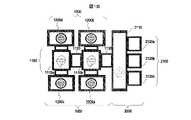
- FIG. 1A is a diagram schematically showing the outline of the configuration of a vacuum processing apparatus having a plasma processing apparatus according to an embodiment of the present invention.
- FIG. 1B is a top view of the vacuum processing apparatus shown in FIG. 1A.
- FIG. 2 is a side view showing a schematic configuration of a vacuum processing unit of the vacuum processing apparatus according to the embodiment shown in FIG.
- FIG. 3 is a schematic plan view of a cross-section of the vacuum processing unit shown in FIG. 2 taken along line AA.
- FIG. 4 is a schematic plan view of a cross section of the vacuum processing unit shown in FIG. 2 taken along line AA.
- FIG. 5 is a side view schematically showing the configuration of the vacuum processing unit shown in FIG. 2, viewed from the side facing the plane BB.
- FIG. 6 is a diagram schematically showing the schematic configuration of the gas supply unit according to the embodiment shown in FIG.
- FIG. 7 is a time chart showing the flow of operations over time for adjusting the temperature of the top plate performed by the plasma processing unit of the vacuum processing apparatus according to the embodiment shown in FIG.
- FIG. 1A is a diagram schematically showing the outline of the configuration of a vacuum processing apparatus having a plasma processing apparatus according to this embodiment, and is a perspective view showing the outline of the overall configuration of the vacuum processing apparatus.
- 1B is a top view of the vacuum processing apparatus shown in FIG. 1A. 1A and 1B, the right side is the front side and the left side is the rear side.
- the vacuum processing apparatus of the present embodiment roughly has a vacuum side block 1000 and an atmosphere side block 2000 along the front-rear direction (left-right direction in the drawing). These are connected through a passage whose communication is airtightly opened and closed by a gate valve (not shown).
- the vacuum-side block 1000 has a vacuum transfer block 1100 and a vacuum processing unit 1200 which are connected to each other. is conveyed.
- the atmosphere-side block 2000 includes an atmosphere transport container 2110 in which the sample is transported, and an atmosphere transport container 2110 in which the internal pressure is maintained at a value equivalent to or close to (in this example, slightly higher than) the atmospheric pressure.
- a cassette mounting table 2100 is arranged on the front surface of the apparatus and has a cassette mounting table 2100 on the upper surface of which a cassette capable of accommodating a plurality of samples to be processed is placed inside.
- three cassette mounting tables 2120 a to 2120 c are arranged horizontally along the front surface of the atmospheric transfer container 2110 .
- the vacuum transfer block 1100 of this example includes a plurality of vacuum transfer containers 1110a and 1110b having a substantially rectangular shape in plan view, an intermediate chamber container 1120 connected to these and communicating with each other, the vacuum transfer container 1110b and the atmosphere. and a lock chamber container 1130 that connects with the transport container 2110 .
- a plurality of vacuum processing units 1200a to 1200d are connected to the side walls of each of the vacuum transfer containers 1110a and 1110b of this example.
- Each of the four vacuum processing units 1200a to 1200d of this example includes a vacuum container having a processing chamber inside which is decompressed to a predetermined degree of vacuum, and a vacuum pump disposed below the chamber for evacuating and decompressing the internal processing chamber. are detachably connected to the side walls of the vacuum vessels and the side walls of the vacuum transfer vessels 1110a and 1110b. Furthermore, a gate, which is a passage that penetrates through these side walls and communicates the insides of both, is arranged, and the gate is airtightly closed or opened by a gate valve (not shown). A sample to be processed is carried in and out between the processing chamber in the vacuum container of the vacuum processing unit 1200 and the transfer chamber in the vacuum transfer container through the opened gate.
- the processing chamber which is the space inside the vacuum vessel, is airtightly sealed with a valve or the like and partitioned, and the interior is evacuated by driving a vacuum pump (see the vacuum pump 202 in FIG. 3). Then, the pressure is reduced to a predetermined pressure.
- a gas for processing the sample is supplied to the decompressed space from a gas supply pipeline connected to a gas storage tank (not shown) as a gas source, and an electric field or a magnetic field is generated from a supply means for supplying an electric field or a magnetic field. is supplied to excite the gas and plasma is formed in the space above the mounting surface of the sample stage.
- the surface on which the cassette mounting tables 2120a to 2120c are arranged on the front side of the housing constituting the atmospheric transfer container 2110 is arranged along the line along which the cassettes are transferred on the floor of a building such as a clean room. spaced apart from the adjacent vacuum processing apparatus.
- the space around the vacuum processing apparatus such as the space between the vacuum processing units 1200 adjacent in the front-rear direction and the space behind the vacuum processing apparatus (left side in FIG. 1B), is used by workers to pass through or perform work. It is a space for work that can be done, and the distance is larger than the width of at least one person in the left and right direction.
- a plurality (two in this example) of vacuum transfer containers 1110a and 1110b are connected in the front-rear direction (left-right direction in FIG. 1B) with an intermediate chamber container 1120 interposed therebetween, They are arranged with their side walls facing each other.
- Each of the vacuum transfer containers 1110a and 1110b has a rectangular shape in a plan view, or a shape similar to the rectangular shape, and is oriented in the left-right direction (the up-down direction in FIG. 1B) when viewed from the front of the vacuum processing apparatus.
- Vacuum processing units 1200 are connected to the side wall surfaces on the sides of .
- Two vacuum processing units 1200 are arranged adjacent to each other with at least a space between the vacuum vessels in the front-rear direction (left-right direction in FIG. 1B). Therefore, this space is a space in which new components can be mounted without interfering with other devices, and is the only space other than the wet cleaning work area and maintenance area of the vacuum processing apparatus.
- FIG. 2 is a side view showing a schematic configuration of a vacuum processing unit 1200 in the vacuum processing apparatus according to the embodiment shown in FIG.
- This embodiment shows the configuration of the vacuum processing units 1200a, 1200b, 1200c, and 1200d shown in FIG. 1B. Therefore, the vacuum processing unit 1200a will be described here as an example.
- the vacuum processing unit 1200a is roughly divided into the following three parts.
- One such part is a processing section 200 including a vacuum vessel 201 (vacuum chamber) having a processing chamber inside, and a vacuum pump 202 including a turbomolecular pump disposed below the vacuum vessel 201 and evacuating the inside of the processing chamber. be.
- the other part is a plasma forming part 300 arranged above the vacuum vessel 201 to form and propagate an electric field or magnetic field to be supplied into the processing chamber.
- the remaining one portion is the bed portion 100 which is arranged below the processing portion 200 and serves as a platform for supporting the processing portion 200 and the plasma forming portion 300 thereabove from below.
- the vacuum container 201 of the processing unit 200 has a processing chamber inside and is partitioned by hermetically sealing the inside from the outside atmosphere.
- the vacuum vessel 201 has, for example, a loading port, that is, an opening at the top for loading the sample into the processing chamber, and the internal space on the side of the opening can be partitioned by a gate valve. It has a structure.
- the processing chamber has an opening through which the substrate is loaded, and has a structure in which the internal space on the side of the opening is kept airtight by the gate valve.
- the processing chamber in the vacuum vessel 201 includes a cylindrical processing chamber, a cylindrical sample stage arranged such that the central axes of the processing chamber coincide with each other or are close to each other, and a sample stage. It has a substrate electrode disposed therein and supplied with a high frequency bias power.
- a sample (wafer) is transported onto the mounting surface of the sample table in the processing chamber of the vacuum vessel 201, and while being held thereon, is generated by plasma generated using a processing gas introduced into the chamber. , a target film having a film structure preliminarily formed and arranged on the sample surface is etched.
- a vacuum pump 202 is arranged below the vacuum vessel 201 and is connected to the vacuum vessel 201 to exhaust the gas in the vacuum vessel.
- the plasma forming section 300 is arranged above the processing container of the processing section 200 .
- a high-frequency oscillator 301, a wafer bias power supply 302, a wafer bias matching device 303, an ESC power supply 304, a coil section 305, and the like are provided.
- the high-frequency oscillator 301 constitutes plasma generating means, and is composed of, for example, a magnetron or the like that forms an electric field for generating plasma in the processing chamber.
- a wafer bias power supply 302 supplies bias power to the substrate electrode.
- the substrate electrode is arranged in the vacuum vessel 201 and has a metallic disk shape arranged inside a sample table on which the sample is placed, adsorbed and held on the mounting surface, which is the upper surface of the sample, during processing.
- a wafer bias matcher 303 adjusts the bias power supplied to the substrate electrode.
- the ESC power supply 304 supplies DC power to the electrodes arranged inside the dielectric film forming the mounting surface of the substrate electrode in order to electrostatically attract the object to be processed to the substrate electrode.
- the substrate electrode is arranged so as to cover the upper surface of the sample stage in order to electrostatically attract the sample onto the mounting surface of the upper surface of the sample stage.
- the coil section 305 is arranged above the vacuum vessel and constitutes plasma generation means including means for generating an electric field and a magnetic field. In this embodiment, it is connected to a portion on the outer peripheral side of the vacuum vessel 201 above the bed section 100, fastened with bolts, screws, or the like, positioned, and arranged parallel to the central axis of the vacuum vessel 201 in the vertical direction. It has a lifter 306 with a shaft. The coil portion 305 is connected to the shaft of the lifter 306 as a single unit, and the portion connected to the coil portion 305 moves up and down along the shaft, thereby moving the coil portion 305 in the vertical direction. can be done.
- the bed section 100 is arranged below the vacuum vessel 201 and the vacuum pump 202 of the processing section 200, and includes a coil power supply, a power distribution unit, a processing chamber mount, a level adjustment adjuster, and the like.
- a cylindrical member that constitutes the vacuum vessel 201 is pivoted using the pivots 203 and 204. can be done.
- FIG. 3 and 4 are diagrams schematically showing a plane view of a cross section of the vacuum processing unit shown in FIG. 2 taken along plane AA.
- the upward arrow in the drawing indicates the direction in which the vacuum transfer container 1110a connected to the vacuum processing unit 1200a is arranged, and the downward arrow in the drawing indicates the horizontal direction when viewed from the front of the vacuum processing apparatus.
- a space in which a work space is arranged in which a worker can pass or work can be performed.
- the lifter 306 is mounted on the upper surface of the outer peripheral region of a base plate 310 which constitutes a part of the vacuum container 201 and is arranged at the lower end of the container and whose lower surface is connected to the vacuum pump 202 .
- the lifter 306 has its vertical shaft body positioned with respect to the base plate 310 and the vacuum vessel 201 by fastening screws, bolts, or the like.
- the shaft of the lifter 306 is rotatably connected to the base plate 310 connected to the cylindrical discharge chamber chamber partial discharge portion and its outer peripheral side, and the discharge base plate and the coil arranged above it are connected to each other.
- Unit 305, high frequency oscillator 301, wafer bias power supply 302, wafer bias matching device 303, and ESC power supply 304 are connected. With this configuration, the discharge unit base plate connected to the lifter 306 is a mechanism for moving up and down.
- the discharge base plate and the upper part thereof are arranged.
- the discharge chamber section, the coil section 305, and the like are lifted by a predetermined distance, and then swung together with the swivel section 203 about the vertical axis of the lifter 306 to open the upper portion of the vacuum vessel 201.
- FIG. Further, the sample stage ring base 402 on which the upper container is placed is rotated about the vertical axis of the lifter 306 together with the swivel part 203, exposing the ring-shaped upper end of the cylindrical lower container 401.
- the lower container 401 is removed from the base plate 310 and maintenance and inspection work is performed on the upper container, the lower container 401 and the base plate 310 .
- FIG. 5 is a side view schematically showing the configuration of the vacuum processing unit shown in FIG. 2, viewed from the side facing the plane BB.
- a gas supply unit UA arranged on the side surface of the lifter 306 and a gas supply unit UA for adjusting the supply of gas for processing the sample supplied into the processing chamber inside the vacuum container 201 of the vacuum processing unit 1200a.
- a gas supply unit UB arranged above the bed section 100 below the gas supply unit UA.
- the gas supply units UA and UB that supply these mixed gases have pipes through which a plurality of types of gases flow in the internal space, and flow controllers and pipes for the respective gases on the pipes that are opened and closed.
- Gas boxes A and B (FIG. 6) in which valves for opening and closing the flow of gas are arranged in parallel and surrounded by a box (container) are provided.
- gas box A of the gas supply unit UA four gas pipes extending in parallel from above a box (referred to as a first box) penetrate the top wall of the box and extend to the inside. In addition, one gas pipe extends downward through the bottom wall of the box.
- gas box B of the gas supply unit UB 20 gas pipes extending upward in parallel from below the bed portion 100 penetrate the bottom wall of the box and extend to the inside, and also penetrate the top wall of the box.
- a single gas pipe extends upward.
- Each of the two gas pipes extending through the bottom wall and the top wall of the upper and lower gas boxes A and B is connected to the vacuum vessel 201 as one mixed gas supply pipe 600 for the processing gas. Connected.
- FIG. 6 is a diagram schematically showing the schematic configuration of the gas supply unit according to the embodiment shown in FIG.
- the gas box A is shown upside down with respect to the arrangement shown in FIG.
- gas box A In the gas box A, four gas supply lines (pipes) a to d are arranged in parallel inside a box having a rectangular shape when viewed from the side.
- a flow controller for increasing or decreasing the flow rate, at least one valve for opening and closing the piping, and a detector for detecting the flow rate or pressure of the gas are provided inside the gas supply lines a to d.
- the material of the raw material which has combustibility such as BCl 3 and becomes a liquid phase at a temperature controlled in a building such as a clean room in which a vacuum processing apparatus is installed, is vaporized.
- a plurality of types of gases including gas hereinafter referred to as low vapor pressure gas
- Low vapor pressure gases include, but are not limited to, SiCl 4 and BCl 3 .
- the lower end sides of the gas supply lines a to d inside the box of the gas box A penetrate the box bottom wall (the box top wall in FIG. 5) and extend to the outside.
- the upper end of each of the gas supply lines a to d is connected to one gas supply pipe (first pipe) y in the space inside the box, and the upper wall of the box (the lower surface of the box in FIG. wall) and extends to the outside.
- a second box a rectangular box
- x are arranged in parallel, and on each pipe there is a flow controller for adjusting the flow rate of gas, at least one valve for opening and closing the pipe, and a detector for detecting the flow rate or pressure of the gas.
- the lower ends of the gas supply lines e to x pass through the bottom wall of the box, extend further downward from the floor of the building in which the vacuum processing apparatus is installed, and are connected to the gas source.
- Each type of gas is supplied to the gas box B from under the floor of the building.
- the upper end sides of the gas supply lines e to x are connected to one gas supply pipe (second pipe) z inside the box and extend outside through the upper wall of the box.
- the gas supply pipe y and the gas supply pipe z are merged, they are connected to one mixed gas supply pipe (third pipe) 600 . Further, the mixed gas supply pipe 600 is connected inside the processing chamber. Therefore, the mixed gas generated by joining the gas supply pipe y and the gas supply pipe z at the connecting portion is supplied as a processing gas into the processing chamber inside the vacuum vessel 201 via the mixed gas supply pipe 600. .
- a valve 601 is arranged on the mixed gas supply pipe 600 to open and close the flow of gas in the pipe.
- the length of the gas supply pipe y from the box of gas box A to the connection point with the mixed gas supply pipe 600, and the gas supply from the box of gas box B to the connection point with the mixed gas supply pipe 600 The lengths of the pipes z are configured to be equal.
- the positions of the gas boxes A and B and the gas supply lines a to x are arranged so that the length of the pipes, including the mixed gas supply pipe 600, from the gas boxes A and B to the vacuum vessel 201 is the shortest.
- the structure of the gas lines such as the arrangement and connection points between the gas supply pipes y and z and the mixed gas supply pipe 600, is appropriately selected.
- gas box A is for supplying multiple types of gases, including low vapor pressure gases.
- gas box B is for supplying normal gas other than low vapor pressure gas.
- a plurality of gas supply pipes for the gas boxes A and B are arranged at positions furthest (uppermost upstream) from the gas outlet for supplying purge gas such as argon gas (Ar gas) and nitrogen gas ( N2 gas). be.
- purge gas such as argon gas (Ar gas) and nitrogen gas ( N2 gas).
- a filter, a manual valve, a regulator, a first air operation valve, a mass flow controller (flow rate regulator), and a second air operation valve are arranged on each gas supply line from the upstream side in the direction of gas flow. .
- the gas boxes A and B are arranged vertically near the connection position with the mixed gas supply pipe 600 .
- the pipes from the gas supply lines in these gas boxes A and B to the connection position with the mixed gas supply pipe 600 are made as short as possible according to the equation of continuity and Bernoulli's theorem for the purpose of improving responsiveness. , is preferably reduced in diameter.
- the distance from each gas supply line to the connection point is configured so that the gas arrival times are equal.
- the box body of the gas box A is connected to a gas exhaust pipe used for adjusting the temperature of a dielectric circular top plate 307 (FIG. 2) that shields the upper part of the vacuum vessel 201, as will be described later.
- the inside of the box A is heated to a temperature of 40 to 50° C., which is higher than the temperature inside the building (normal temperature) and can suppress the liquefaction of the low vapor pressure gas, by using the heat of the exhausted gas.
- dividing the gas supply units UA and UB has the following advantages.
- Gas box A accommodates only low vapor pressure gas piping and purge gas piping. can be heated effectively.
- the top plate 307 in this embodiment constitutes the upper lid of the vacuum vessel 201 of the vacuum processing unit 1200a, and transmits a high-frequency electric field, for example, in the microwave band, formed and transmitted by the high-frequency oscillator 301 such as a magnetron, to the vacuum vessel. It has a function of introducing into the inside of 201 from above. Therefore, it is necessary to adjust the temperature of the top plate 307 to a value within a predetermined range (90° C. in this example). For temperature control, a cylindrical cavity vessel connected to the lower end of the waveguide and having the same or slightly larger diameter than the top panel 307 is placed above the top panel 307.
- Air heated by heaters 308 and 309 arranged on the outer peripheral side of the waveguide through which the high-frequency electric field propagates is introduced through the introduction port. Also, the heated air is discharged from the hollow container through an outlet. Thereby, the temperature of the top plate 307 is adjusted.
- FIG. 7 is a time chart showing the flow of operations over time for adjusting the top plate temperature performed by the plasma processing unit of the vacuum processing apparatus shown in FIG.
- the values on the vertical axis represent, from the top, the temperature [° C.] of the top plate 307 in FIG. 2, heater ON/OFF timing, and plasma ON/OFF timing.
- a control device (not shown) can control the heater in conjunction with plasma deactivation.
- the top plate 307 When plasma is formed in the processing chamber within the vacuum vessel 201 at time t1, the top plate 307 is also warmed by the heat input from the formed plasma during the processing of the sample. Therefore, if power is continuously supplied to the heaters 308 and 309, the temperature of the top plate 307 may increase beyond the desired range.
- the power supply to the heaters 308 and 309 is stopped, and the air in the building around the vacuum processing unit 1200a, which is generally maintained at a so-called normal temperature of about 25° C., is removed from the heaters 308 and 309 whose heat generation is interrupted. It is fed into the hollow container from the passage inlet.
- the air heated by the plasma and having a temperature lower than the temperature of the top plate 307 swirls and flows over the back surface (upper surface) of the top plate 307 for heat exchange.
- the temperature of 307 does not rise too high and remains within the desired range.
- the heating of the top plate 307 by the plasma is interrupted. be done.
- the air heated by the heaters 308 and 309 is supplied from the inlet into the hollow container, and heats the top plate 307, thereby maintaining the temperature of the top plate 307 at a value equivalent to that during processing until time t3.
- the temperature of the top plate 307 is similarly adjusted while alternately repeating plasma generation (t3 to t4) and power supply to the heaters 308 and 309 (t4 to t5).
- the air heated by the heaters 308 and 309 and supplied into the hollow container for adjusting the temperature of the top plate 307 is exhausted from the exhaust port formed in the waveguide after sufficient heat exchange. be.
- the air is exhausted, it is heated to a predetermined temperature higher than room temperature by the heaters 308, 309 or plasma, so if the air is discharged into the building, the thermal energy contained in the air is wasted. Therefore, in this embodiment, the thermal energy of the exhausted air is effectively used.
- the exhausted air is introduced into the box body of the gas box A through the air inlet 603 of the gas box A shown in FIG.
- the heat of the air used to adjust the temperature of the top plate 307 is used to heat the piping of the gas supply line inside the box, and the temperature of the low vapor pressure gas flowing through it is 40 to 40.
- the temperature is set to 50° C., liquefaction of the low vapor pressure gas can be suppressed.
- the gas box A is placed at a position close to the air exhaust port of the hollow container (for example, within 2m). By arranging in such a position, it is possible to prevent the exhaust air from being excessively cooled while moving from the waveguide outlet to the air inlet 603 of the gas box A.
- the air inlet 603 and the air outlet 604 are arranged in parallel with the gas supply line a so that the air fills the inside of the gas box A and can sufficiently exchange heat with the gas flowing through the gas supply line.
- 1 to d are arranged on both sides of the side walls in the row direction, and are also arranged on the upper end of one side wall and the lower end of the other side, and are arranged at different height positions in the vertical direction so that the air can flow into the box. They are arranged so as to flow inside from one diagonal position toward the other diagonal position.
- the low-vapor-pressure gas piping be arranged closer to the air inlet port 603 than the purge gas piping.
- the heat of the air used to adjust the temperature of the top plate 307 is used to heat the gas supply pipe of the gas box A, which has the following advantages.
- the temperature of the entire inside of the gas box A can be raised uniformly, the occurrence of local cold spots can be suppressed, and the adverse effects of liquefaction of low vapor pressure gas can be suppressed.
- a low vapor pressure gas that may be liquefied is separated from other types of gas, and a gas supply pipe is arranged, and a gas supply pipe including a flow controller for the low vapor pressure gas is arranged. It is possible to increase the temperature inside the housing and reduce the liquefaction of the gas, contributing to the improvement of the safety and reliability of the plasma processing apparatus.
Landscapes
- Physics & Mathematics (AREA)
- Engineering & Computer Science (AREA)
- Plasma & Fusion (AREA)
- Chemical & Material Sciences (AREA)
- Analytical Chemistry (AREA)
- Drying Of Semiconductors (AREA)
- Treatment Of Fiber Materials (AREA)
Priority Applications (6)
| Application Number | Priority Date | Filing Date | Title |
|---|---|---|---|
| US17/908,781 US12494347B2 (en) | 2021-06-21 | 2021-06-21 | Plasma processing apparatus |
| CN202180017653.9A CN115715424A (zh) | 2021-06-21 | 2021-06-21 | 等离子体处理装置 |
| KR1020227029789A KR102837447B1 (ko) | 2021-06-21 | 2021-06-21 | 플라스마 처리 장치 |
| PCT/JP2021/023318 WO2022269659A1 (ja) | 2021-06-21 | 2021-06-21 | プラズマ処理装置 |
| JP2022546089A JP7386348B2 (ja) | 2021-06-21 | 2021-06-21 | プラズマ処理装置 |
| TW111122807A TWI827101B (zh) | 2021-06-21 | 2022-06-20 | 電漿處理裝置 |
Applications Claiming Priority (1)
| Application Number | Priority Date | Filing Date | Title |
|---|---|---|---|
| PCT/JP2021/023318 WO2022269659A1 (ja) | 2021-06-21 | 2021-06-21 | プラズマ処理装置 |
Publications (1)
| Publication Number | Publication Date |
|---|---|
| WO2022269659A1 true WO2022269659A1 (ja) | 2022-12-29 |
Family
ID=84544293
Family Applications (1)
| Application Number | Title | Priority Date | Filing Date |
|---|---|---|---|
| PCT/JP2021/023318 Ceased WO2022269659A1 (ja) | 2021-06-21 | 2021-06-21 | プラズマ処理装置 |
Country Status (6)
| Country | Link |
|---|---|
| US (1) | US12494347B2 (https=) |
| JP (1) | JP7386348B2 (https=) |
| KR (1) | KR102837447B1 (https=) |
| CN (1) | CN115715424A (https=) |
| TW (1) | TWI827101B (https=) |
| WO (1) | WO2022269659A1 (https=) |
Cited By (1)
| Publication number | Priority date | Publication date | Assignee | Title |
|---|---|---|---|---|
| WO2025063138A1 (ja) * | 2023-09-21 | 2025-03-27 | 株式会社フジキン | 金属配管の固定構造 |
Citations (4)
| Publication number | Priority date | Publication date | Assignee | Title |
|---|---|---|---|---|
| JPH11168092A (ja) * | 1997-12-04 | 1999-06-22 | Denso Corp | 気相成長方法および気相成長装置 |
| JP2001044186A (ja) * | 1999-07-27 | 2001-02-16 | Tokyo Electron Ltd | 成膜装置 |
| JP2008053456A (ja) * | 2006-08-24 | 2008-03-06 | Fujitsu Ltd | 処理ガス供給方法、基板処理方法、半導体装置の製造方法、処理ガス供給装置、基板処理装置、および記録媒体 |
| JP2011100820A (ja) * | 2009-11-05 | 2011-05-19 | Hitachi Kokusai Electric Inc | 基板処理装置 |
Family Cites Families (31)
| Publication number | Priority date | Publication date | Assignee | Title |
|---|---|---|---|---|
| JP3099441B2 (ja) | 1991-08-08 | 2000-10-16 | 日本電気株式会社 | 特殊材料ガスの供給方法 |
| JP3520614B2 (ja) * | 1995-07-26 | 2004-04-19 | 株式会社デンソー | ヘッドアップディスプレイ装置 |
| JP3684624B2 (ja) | 1995-08-02 | 2005-08-17 | ソニー株式会社 | 反応ガス供給装置 |
| US5958510A (en) * | 1996-01-08 | 1999-09-28 | Applied Materials, Inc. | Method and apparatus for forming a thin polymer layer on an integrated circuit structure |
| JP3139369B2 (ja) * | 1996-04-19 | 2001-02-26 | 日本電気株式会社 | 薄膜キャパシタの形成方法 |
| US5997642A (en) * | 1996-05-21 | 1999-12-07 | Symetrix Corporation | Method and apparatus for misted deposition of integrated circuit quality thin films |
| JP3009371B2 (ja) * | 1997-03-14 | 2000-02-14 | ニチメン電子工研株式会社 | ダイヤモンド様炭素膜堆積装置 |
| JP2000150387A (ja) | 1998-11-18 | 2000-05-30 | Applied Materials Inc | 配管系構造及び配管系ユニット |
| CN1322556C (zh) * | 2001-02-15 | 2007-06-20 | 东京毅力科创株式会社 | 被处理件的处理方法及处理装置 |
| US20030005943A1 (en) | 2001-05-04 | 2003-01-09 | Lam Research Corporation | High pressure wafer-less auto clean for etch applications |
| US6815362B1 (en) | 2001-05-04 | 2004-11-09 | Lam Research Corporation | End point determination of process residues in wafer-less auto clean process using optical emission spectroscopy |
| US20040235303A1 (en) | 2001-05-04 | 2004-11-25 | Lam Research Corporation | Endpoint determination of process residues in wafer-less auto clean process using optical emission spectroscopy |
| US7204913B1 (en) | 2002-06-28 | 2007-04-17 | Lam Research Corporation | In-situ pre-coating of plasma etch chamber for improved productivity and chamber condition control |
| US20040014327A1 (en) | 2002-07-18 | 2004-01-22 | Bing Ji | Method for etching high dielectric constant materials and for cleaning deposition chambers for high dielectric constant materials |
| JP2007109840A (ja) * | 2005-10-13 | 2007-04-26 | Ishikawajima Harima Heavy Ind Co Ltd | 水蒸気アニール装置および水蒸気アニール方法 |
| JP2008060171A (ja) | 2006-08-29 | 2008-03-13 | Taiyo Nippon Sanso Corp | 半導体処理装置のクリーニング方法 |
| JP5042686B2 (ja) * | 2007-03-30 | 2012-10-03 | 株式会社日立ハイテクノロジーズ | プラズマ処理装置 |
| JP2009084625A (ja) * | 2007-09-28 | 2009-04-23 | Tokyo Electron Ltd | 原料ガスの供給システム及び成膜装置 |
| FI122941B (fi) * | 2008-06-12 | 2012-09-14 | Beneq Oy | Sovitelma ALD-reaktorin yhteydessä |
| KR101630234B1 (ko) | 2009-11-17 | 2016-06-15 | 주성엔지니어링(주) | 공정챔버의 세정방법 |
| KR20130004238A (ko) | 2009-11-27 | 2013-01-09 | 가부시키가이샤 한도오따이 에네루기 켄큐쇼 | 액정 표시 장치 |
| JP5450187B2 (ja) | 2010-03-16 | 2014-03-26 | 株式会社日立ハイテクノロジーズ | プラズマ処理装置およびプラズマ処理方法 |
| JP5530794B2 (ja) | 2010-04-28 | 2014-06-25 | 株式会社日立ハイテクノロジーズ | 真空処理装置及びプラズマ処理方法 |
| JPWO2011158691A1 (ja) | 2010-06-16 | 2013-08-19 | 日本電気株式会社 | 抵抗変化素子及び抵抗変化素子の製造方法 |
| US9533332B2 (en) | 2011-10-06 | 2017-01-03 | Applied Materials, Inc. | Methods for in-situ chamber clean utilized in an etching processing chamber |
| JP6184760B2 (ja) * | 2013-06-11 | 2017-08-23 | 東京エレクトロン株式会社 | 基板処理方法及び基板処理装置 |
| US9885493B2 (en) * | 2013-07-17 | 2018-02-06 | Lam Research Corporation | Air cooled faraday shield and methods for using the same |
| JP6169666B2 (ja) | 2015-10-20 | 2017-07-26 | 株式会社日立ハイテクノロジーズ | プラズマ処理方法 |
| JP6499980B2 (ja) | 2016-01-04 | 2019-04-10 | 株式会社日立ハイテクノロジーズ | プラズマ処理方法 |
| JP6630649B2 (ja) | 2016-09-16 | 2020-01-15 | 株式会社日立ハイテクノロジーズ | プラズマ処理方法 |
| JP6980406B2 (ja) * | 2017-04-25 | 2021-12-15 | 株式会社日立ハイテク | 半導体製造装置及び半導体装置の製造方法 |
-
2021
- 2021-06-21 CN CN202180017653.9A patent/CN115715424A/zh active Pending
- 2021-06-21 WO PCT/JP2021/023318 patent/WO2022269659A1/ja not_active Ceased
- 2021-06-21 US US17/908,781 patent/US12494347B2/en active Active
- 2021-06-21 JP JP2022546089A patent/JP7386348B2/ja active Active
- 2021-06-21 KR KR1020227029789A patent/KR102837447B1/ko active Active
-
2022
- 2022-06-20 TW TW111122807A patent/TWI827101B/zh active
Patent Citations (4)
| Publication number | Priority date | Publication date | Assignee | Title |
|---|---|---|---|---|
| JPH11168092A (ja) * | 1997-12-04 | 1999-06-22 | Denso Corp | 気相成長方法および気相成長装置 |
| JP2001044186A (ja) * | 1999-07-27 | 2001-02-16 | Tokyo Electron Ltd | 成膜装置 |
| JP2008053456A (ja) * | 2006-08-24 | 2008-03-06 | Fujitsu Ltd | 処理ガス供給方法、基板処理方法、半導体装置の製造方法、処理ガス供給装置、基板処理装置、および記録媒体 |
| JP2011100820A (ja) * | 2009-11-05 | 2011-05-19 | Hitachi Kokusai Electric Inc | 基板処理装置 |
Cited By (1)
| Publication number | Priority date | Publication date | Assignee | Title |
|---|---|---|---|---|
| WO2025063138A1 (ja) * | 2023-09-21 | 2025-03-27 | 株式会社フジキン | 金属配管の固定構造 |
Also Published As
| Publication number | Publication date |
|---|---|
| TW202301417A (zh) | 2023-01-01 |
| US20240194453A1 (en) | 2024-06-13 |
| CN115715424A (zh) | 2023-02-24 |
| KR20230001008A (ko) | 2023-01-03 |
| TWI827101B (zh) | 2023-12-21 |
| KR102837447B1 (ko) | 2025-07-25 |
| JPWO2022269659A1 (https=) | 2022-12-29 |
| US12494347B2 (en) | 2025-12-09 |
| JP7386348B2 (ja) | 2023-11-24 |
Similar Documents
| Publication | Publication Date | Title |
|---|---|---|
| US6176198B1 (en) | Apparatus and method for depositing low K dielectric materials | |
| KR101989141B1 (ko) | 성막 장치, 성막 장치의 클리닝 방법 및 기억 매체 | |
| TWI416643B (zh) | Vacuum isolation device and treatment method | |
| KR102282154B1 (ko) | 기판 처리 장치 및 반도체 장치의 제조 방법 및 프로그램 | |
| KR101665371B1 (ko) | 기판 처리 장치, 반도체 장치의 제조 방법 및 기록 매체 | |
| JP2008202107A (ja) | 基板処理装置 | |
| JP2010129666A (ja) | 基板処理装置及び半導体装置の製造方法 | |
| WO2018167846A1 (ja) | 基板処理装置、半導体装置の製造方法およびプログラム | |
| JP2009088315A (ja) | 基板処理装置 | |
| JP4927623B2 (ja) | ロードロック装置の昇圧方法 | |
| KR101116875B1 (ko) | 진공처리장치 | |
| JP6176732B2 (ja) | ガス供給部、基板処理装置及び半導体装置の製造方法 | |
| WO2022269659A1 (ja) | プラズマ処理装置 | |
| JP2008300444A (ja) | 半導体製造装置 | |
| JP6202720B2 (ja) | プラズマ処理装置およびプラズマ処理方法 | |
| JP5825948B2 (ja) | 基板処理装置及び半導体装置の製造方法 | |
| JP3738494B2 (ja) | 枚葉式の熱処理装置 | |
| JP2013062271A (ja) | 基板処理装置 | |
| JP2009224457A (ja) | 基板処理装置 | |
| JP2016162794A (ja) | 真空処理装置 | |
| JP2009123950A (ja) | 基板処理装置 | |
| JP2004339566A (ja) | 基板処理装置 | |
| CN100543935C (zh) | 成膜和清洁方法 | |
| JPWO2022269659A5 (https=) | ||
| JPH0521867Y2 (https=) |
Legal Events
| Date | Code | Title | Description |
|---|---|---|---|
| ENP | Entry into the national phase |
Ref document number: 2022546089 Country of ref document: JP Kind code of ref document: A |
|
| WWE | Wipo information: entry into national phase |
Ref document number: 17908781 Country of ref document: US |
|
| 121 | Ep: the epo has been informed by wipo that ep was designated in this application |
Ref document number: 21946950 Country of ref document: EP Kind code of ref document: A1 |
|
| NENP | Non-entry into the national phase |
Ref country code: DE |
|
| 122 | Ep: pct application non-entry in european phase |
Ref document number: 21946950 Country of ref document: EP Kind code of ref document: A1 |