WO2022269659A1 - プラズマ処理装置 - Google Patents
プラズマ処理装置 Download PDFInfo
- Publication number
- WO2022269659A1 WO2022269659A1 PCT/JP2021/023318 JP2021023318W WO2022269659A1 WO 2022269659 A1 WO2022269659 A1 WO 2022269659A1 JP 2021023318 W JP2021023318 W JP 2021023318W WO 2022269659 A1 WO2022269659 A1 WO 2022269659A1
- Authority
- WO
- WIPO (PCT)
- Prior art keywords
- gas
- box
- processing apparatus
- pipe
- plasma processing
- Prior art date
Links
- 238000009832 plasma treatment Methods 0.000 title abstract 3
- 239000007789 gas Substances 0.000 claims abstract description 224
- 238000012545 processing Methods 0.000 claims description 162
- 238000010438 heat treatment Methods 0.000 claims description 4
- 238000012546 transfer Methods 0.000 description 16
- 238000010926 purge Methods 0.000 description 9
- 239000000758 substrate Substances 0.000 description 9
- 230000005684 electric field Effects 0.000 description 7
- 238000012423 maintenance Methods 0.000 description 6
- 239000000463 material Substances 0.000 description 6
- 229910003902 SiCl 4 Inorganic materials 0.000 description 5
- 238000010586 diagram Methods 0.000 description 5
- YCKRFDGAMUMZLT-UHFFFAOYSA-N Fluorine atom Chemical compound [F] YCKRFDGAMUMZLT-UHFFFAOYSA-N 0.000 description 4
- 238000004140 cleaning Methods 0.000 description 4
- 229910052731 fluorine Inorganic materials 0.000 description 4
- 239000011737 fluorine Substances 0.000 description 4
- 238000000034 method Methods 0.000 description 4
- 230000002093 peripheral effect Effects 0.000 description 4
- ZOXJGFHDIHLPTG-UHFFFAOYSA-N Boron Chemical compound [B] ZOXJGFHDIHLPTG-UHFFFAOYSA-N 0.000 description 3
- 229910052796 boron Inorganic materials 0.000 description 3
- XKRFYHLGVUSROY-UHFFFAOYSA-N Argon Chemical compound [Ar] XKRFYHLGVUSROY-UHFFFAOYSA-N 0.000 description 2
- 238000000151 deposition Methods 0.000 description 2
- 238000007689 inspection Methods 0.000 description 2
- VNWKTOKETHGBQD-UHFFFAOYSA-N methane Chemical compound C VNWKTOKETHGBQD-UHFFFAOYSA-N 0.000 description 2
- 230000008569 process Effects 0.000 description 2
- 230000002829 reductive effect Effects 0.000 description 2
- 230000004043 responsiveness Effects 0.000 description 2
- 238000011144 upstream manufacturing Methods 0.000 description 2
- IJGRMHOSHXDMSA-UHFFFAOYSA-N Atomic nitrogen Chemical compound N#N IJGRMHOSHXDMSA-UHFFFAOYSA-N 0.000 description 1
- XUIMIQQOPSSXEZ-UHFFFAOYSA-N Silicon Chemical compound [Si] XUIMIQQOPSSXEZ-UHFFFAOYSA-N 0.000 description 1
- 230000002411 adverse Effects 0.000 description 1
- 229910052786 argon Inorganic materials 0.000 description 1
- 238000004891 communication Methods 0.000 description 1
- 238000007796 conventional method Methods 0.000 description 1
- 230000009849 deactivation Effects 0.000 description 1
- 230000003247 decreasing effect Effects 0.000 description 1
- 230000008021 deposition Effects 0.000 description 1
- 229910001873 dinitrogen Inorganic materials 0.000 description 1
- 238000009826 distribution Methods 0.000 description 1
- 230000000694 effects Effects 0.000 description 1
- 238000005530 etching Methods 0.000 description 1
- 230000020169 heat generation Effects 0.000 description 1
- 230000006872 improvement Effects 0.000 description 1
- 230000002452 interceptive effect Effects 0.000 description 1
- 238000005304 joining Methods 0.000 description 1
- 239000007791 liquid phase Substances 0.000 description 1
- 230000007246 mechanism Effects 0.000 description 1
- 239000002184 metal Substances 0.000 description 1
- 230000036961 partial effect Effects 0.000 description 1
- 238000001020 plasma etching Methods 0.000 description 1
- 238000002360 preparation method Methods 0.000 description 1
- 239000002994 raw material Substances 0.000 description 1
- 238000007789 sealing Methods 0.000 description 1
- 239000004065 semiconductor Substances 0.000 description 1
- 229910052710 silicon Inorganic materials 0.000 description 1
- 239000010703 silicon Substances 0.000 description 1
- 238000003860 storage Methods 0.000 description 1
- 238000004381 surface treatment Methods 0.000 description 1
Images


Classifications
-
- H—ELECTRICITY
- H01—ELECTRIC ELEMENTS
- H01J—ELECTRIC DISCHARGE TUBES OR DISCHARGE LAMPS
- H01J37/00—Discharge tubes with provision for introducing objects or material to be exposed to the discharge, e.g. for the purpose of examination or processing thereof
- H01J37/32—Gas-filled discharge tubes
- H01J37/32431—Constructional details of the reactor
- H01J37/32458—Vessel
- H01J37/32522—Temperature
-
- H—ELECTRICITY
- H01—ELECTRIC ELEMENTS
- H01J—ELECTRIC DISCHARGE TUBES OR DISCHARGE LAMPS
- H01J37/00—Discharge tubes with provision for introducing objects or material to be exposed to the discharge, e.g. for the purpose of examination or processing thereof
- H01J37/32—Gas-filled discharge tubes
- H01J37/32431—Constructional details of the reactor
- H01J37/3244—Gas supply means
- H01J37/32449—Gas control, e.g. control of the gas flow
-
- H—ELECTRICITY
- H01—ELECTRIC ELEMENTS
- H01L—SEMICONDUCTOR DEVICES NOT COVERED BY CLASS H10
- H01L21/00—Processes or apparatus adapted for the manufacture or treatment of semiconductor or solid state devices or of parts thereof
- H01L21/02—Manufacture or treatment of semiconductor devices or of parts thereof
- H01L21/04—Manufacture or treatment of semiconductor devices or of parts thereof the devices having at least one potential-jump barrier or surface barrier, e.g. PN junction, depletion layer or carrier concentration layer
- H01L21/18—Manufacture or treatment of semiconductor devices or of parts thereof the devices having at least one potential-jump barrier or surface barrier, e.g. PN junction, depletion layer or carrier concentration layer the devices having semiconductor bodies comprising elements of Group IV of the Periodic System or AIIIBV compounds with or without impurities, e.g. doping materials
- H01L21/30—Treatment of semiconductor bodies using processes or apparatus not provided for in groups H01L21/20 - H01L21/26
- H01L21/31—Treatment of semiconductor bodies using processes or apparatus not provided for in groups H01L21/20 - H01L21/26 to form insulating layers thereon, e.g. for masking or by using photolithographic techniques; After treatment of these layers; Selection of materials for these layers
-
- H—ELECTRICITY
- H01—ELECTRIC ELEMENTS
- H01J—ELECTRIC DISCHARGE TUBES OR DISCHARGE LAMPS
- H01J2237/00—Discharge tubes exposing object to beam, e.g. for analysis treatment, etching, imaging
- H01J2237/32—Processing objects by plasma generation
- H01J2237/33—Processing objects by plasma generation characterised by the type of processing
- H01J2237/332—Coating
- H01J2237/3321—CVD [Chemical Vapor Deposition]
-
- H—ELECTRICITY
- H01—ELECTRIC ELEMENTS
- H01J—ELECTRIC DISCHARGE TUBES OR DISCHARGE LAMPS
- H01J2237/00—Discharge tubes exposing object to beam, e.g. for analysis treatment, etching, imaging
- H01J2237/32—Processing objects by plasma generation
- H01J2237/33—Processing objects by plasma generation characterised by the type of processing
- H01J2237/334—Etching
Definitions
- the present invention relates to a plasma processing apparatus.
- a plasma processing apparatus that supplies a plurality of gases to a processing chamber in a vacuum chamber to process a sample on a substrate to be processed such as a semiconductor wafer placed in the processing chamber, and processes a mixed gas composed of a plurality of types of gases. Feeding as a gas is performed.
- Conventional techniques using such a plasma processing apparatus are disclosed in Patent Documents 1 and 2, for example.
- a mixed gas of SiCl 4 gas and O 2 gas or a mixed gas of SiCl 4 gas and methane gas is used to form a plasma in the processing chamber, thereby depositing a film in the processing chamber. deposit.
- the inside of the processing chamber is plasma-cleaned using a first gas containing elemental fluorine, and the inside of the processing chamber is plasma-cleaned.
- the material to be processed is placed on a sample stage arranged in the processing chamber, and after placing the material to be processed on the sample stage, the material to be processed is plasma-etched, and the material to be processed is plasma-etched.
- the inside of the processing chamber is plasma-cleaned using a second gas containing elemental fluorine.
- Patent Document 2 when plasma etching is performed on a sample in which a film containing a metal element is arranged in the processing chamber, plasma is generated in the processing chamber using a gas containing the boron element. After the plasma cleaning, plasma is used to remove the boron element. Further, after removing the boron element, the inside of the processing chamber is plasma-cleaned using a fluorine-containing gas, and after the plasma cleaning with the fluorine-containing gas, a plasma is applied using a silicon-containing gas to deposit a film. is deposited in the processing chamber, and after the deposition of the deposited film, the sample is plasma etched.
- the above prior art has the following problems. That is, in the prior art, when forming plasma for etching a material to be processed using a mixed gas, it is required to control the gas temperature within an appropriate range so that each gas maintains its gaseous state. .
- a gas with a low vapor pressure such as SiCl 4 has a condensing temperature close to room temperature. It requires ingenuity.
- a heater is generally wrapped around the pipe for supplying the SiCl 4 gas to heat it, and the temperature of the gas is kept within a range that can maintain the gaseous state. It is possible to take measures to maintain
- gas pipes for supplying a plurality of types of gases are arranged at one location so as to pass through one container (gas box).
- the volume of the gas box becomes large, which causes interference with other parts and makes it difficult to secure the mounting space.
- gas purging is normally performed inside the gas box to release gas leaking from pipe joints to the outside, but the increase in the volume inside the gas box container may reduce the gas purging efficiency. .
- the present invention has been made in view of the above problems, and an object of the present invention is to provide a highly safe plasma processing apparatus while suppressing running costs.
- one typical plasma processing apparatus of the present invention includes a vacuum vessel, a processing chamber arranged inside the vacuum vessel, and the A plasma processing apparatus comprising a gas supply unit having a pipe for supplying a low vapor pressure gas into the processing chamber, This is achieved by maintaining the low vapor pressure gas passing through the piping in a gaseous state by supplying air at a temperature higher than normal temperature around the piping.
- One of the representative plasma processing apparatuses of the present invention includes a vacuum vessel, a processing chamber arranged inside the vacuum vessel, and a processing gas supplied to the processing chamber to form plasma in the processing chamber.
- a plasma processing apparatus comprising a gas supply unit having a processing gas line for The processing unit has a plurality of pipes for circulating a plurality of types of gases for each type, and a box surrounding the pipes, This is achieved by supplying the box with air whose temperature is controlled within a predetermined range.
- FIG. 1A is a diagram schematically showing the outline of the configuration of a vacuum processing apparatus having a plasma processing apparatus according to an embodiment of the present invention.
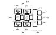
- FIG. 1B is a top view of the vacuum processing apparatus shown in FIG. 1A.
- FIG. 2 is a side view showing a schematic configuration of a vacuum processing unit of the vacuum processing apparatus according to the embodiment shown in FIG.
- FIG. 3 is a schematic plan view of a cross-section of the vacuum processing unit shown in FIG. 2 taken along line AA.
- FIG. 4 is a schematic plan view of a cross section of the vacuum processing unit shown in FIG. 2 taken along line AA.
- FIG. 5 is a side view schematically showing the configuration of the vacuum processing unit shown in FIG. 2, viewed from the side facing the plane BB.
- FIG. 6 is a diagram schematically showing the schematic configuration of the gas supply unit according to the embodiment shown in FIG.
- FIG. 7 is a time chart showing the flow of operations over time for adjusting the temperature of the top plate performed by the plasma processing unit of the vacuum processing apparatus according to the embodiment shown in FIG.
- FIG. 1A is a diagram schematically showing the outline of the configuration of a vacuum processing apparatus having a plasma processing apparatus according to this embodiment, and is a perspective view showing the outline of the overall configuration of the vacuum processing apparatus.
- 1B is a top view of the vacuum processing apparatus shown in FIG. 1A. 1A and 1B, the right side is the front side and the left side is the rear side.
- the vacuum processing apparatus of the present embodiment roughly has a vacuum side block 1000 and an atmosphere side block 2000 along the front-rear direction (left-right direction in the drawing). These are connected through a passage whose communication is airtightly opened and closed by a gate valve (not shown).
- the vacuum-side block 1000 has a vacuum transfer block 1100 and a vacuum processing unit 1200 which are connected to each other. is conveyed.
- the atmosphere-side block 2000 includes an atmosphere transport container 2110 in which the sample is transported, and an atmosphere transport container 2110 in which the internal pressure is maintained at a value equivalent to or close to (in this example, slightly higher than) the atmospheric pressure.
- a cassette mounting table 2100 is arranged on the front surface of the apparatus and has a cassette mounting table 2100 on the upper surface of which a cassette capable of accommodating a plurality of samples to be processed is placed inside.
- three cassette mounting tables 2120 a to 2120 c are arranged horizontally along the front surface of the atmospheric transfer container 2110 .
- the vacuum transfer block 1100 of this example includes a plurality of vacuum transfer containers 1110a and 1110b having a substantially rectangular shape in plan view, an intermediate chamber container 1120 connected to these and communicating with each other, the vacuum transfer container 1110b and the atmosphere. and a lock chamber container 1130 that connects with the transport container 2110 .
- a plurality of vacuum processing units 1200a to 1200d are connected to the side walls of each of the vacuum transfer containers 1110a and 1110b of this example.
- Each of the four vacuum processing units 1200a to 1200d of this example includes a vacuum container having a processing chamber inside which is decompressed to a predetermined degree of vacuum, and a vacuum pump disposed below the chamber for evacuating and decompressing the internal processing chamber. are detachably connected to the side walls of the vacuum vessels and the side walls of the vacuum transfer vessels 1110a and 1110b. Furthermore, a gate, which is a passage that penetrates through these side walls and communicates the insides of both, is arranged, and the gate is airtightly closed or opened by a gate valve (not shown). A sample to be processed is carried in and out between the processing chamber in the vacuum container of the vacuum processing unit 1200 and the transfer chamber in the vacuum transfer container through the opened gate.
- the processing chamber which is the space inside the vacuum vessel, is airtightly sealed with a valve or the like and partitioned, and the interior is evacuated by driving a vacuum pump (see the vacuum pump 202 in FIG. 3). Then, the pressure is reduced to a predetermined pressure.
- a gas for processing the sample is supplied to the decompressed space from a gas supply pipeline connected to a gas storage tank (not shown) as a gas source, and an electric field or a magnetic field is generated from a supply means for supplying an electric field or a magnetic field. is supplied to excite the gas and plasma is formed in the space above the mounting surface of the sample stage.
- the surface on which the cassette mounting tables 2120a to 2120c are arranged on the front side of the housing constituting the atmospheric transfer container 2110 is arranged along the line along which the cassettes are transferred on the floor of a building such as a clean room. spaced apart from the adjacent vacuum processing apparatus.
- the space around the vacuum processing apparatus such as the space between the vacuum processing units 1200 adjacent in the front-rear direction and the space behind the vacuum processing apparatus (left side in FIG. 1B), is used by workers to pass through or perform work. It is a space for work that can be done, and the distance is larger than the width of at least one person in the left and right direction.
- a plurality (two in this example) of vacuum transfer containers 1110a and 1110b are connected in the front-rear direction (left-right direction in FIG. 1B) with an intermediate chamber container 1120 interposed therebetween, They are arranged with their side walls facing each other.
- Each of the vacuum transfer containers 1110a and 1110b has a rectangular shape in a plan view, or a shape similar to the rectangular shape, and is oriented in the left-right direction (the up-down direction in FIG. 1B) when viewed from the front of the vacuum processing apparatus.
- Vacuum processing units 1200 are connected to the side wall surfaces on the sides of .
- Two vacuum processing units 1200 are arranged adjacent to each other with at least a space between the vacuum vessels in the front-rear direction (left-right direction in FIG. 1B). Therefore, this space is a space in which new components can be mounted without interfering with other devices, and is the only space other than the wet cleaning work area and maintenance area of the vacuum processing apparatus.
- FIG. 2 is a side view showing a schematic configuration of a vacuum processing unit 1200 in the vacuum processing apparatus according to the embodiment shown in FIG.
- This embodiment shows the configuration of the vacuum processing units 1200a, 1200b, 1200c, and 1200d shown in FIG. 1B. Therefore, the vacuum processing unit 1200a will be described here as an example.
- the vacuum processing unit 1200a is roughly divided into the following three parts.
- One such part is a processing section 200 including a vacuum vessel 201 (vacuum chamber) having a processing chamber inside, and a vacuum pump 202 including a turbomolecular pump disposed below the vacuum vessel 201 and evacuating the inside of the processing chamber. be.
- the other part is a plasma forming part 300 arranged above the vacuum vessel 201 to form and propagate an electric field or magnetic field to be supplied into the processing chamber.
- the remaining one portion is the bed portion 100 which is arranged below the processing portion 200 and serves as a platform for supporting the processing portion 200 and the plasma forming portion 300 thereabove from below.
- the vacuum container 201 of the processing unit 200 has a processing chamber inside and is partitioned by hermetically sealing the inside from the outside atmosphere.
- the vacuum vessel 201 has, for example, a loading port, that is, an opening at the top for loading the sample into the processing chamber, and the internal space on the side of the opening can be partitioned by a gate valve. It has a structure.
- the processing chamber has an opening through which the substrate is loaded, and has a structure in which the internal space on the side of the opening is kept airtight by the gate valve.
- the processing chamber in the vacuum vessel 201 includes a cylindrical processing chamber, a cylindrical sample stage arranged such that the central axes of the processing chamber coincide with each other or are close to each other, and a sample stage. It has a substrate electrode disposed therein and supplied with a high frequency bias power.
- a sample (wafer) is transported onto the mounting surface of the sample table in the processing chamber of the vacuum vessel 201, and while being held thereon, is generated by plasma generated using a processing gas introduced into the chamber. , a target film having a film structure preliminarily formed and arranged on the sample surface is etched.
- a vacuum pump 202 is arranged below the vacuum vessel 201 and is connected to the vacuum vessel 201 to exhaust the gas in the vacuum vessel.
- the plasma forming section 300 is arranged above the processing container of the processing section 200 .
- a high-frequency oscillator 301, a wafer bias power supply 302, a wafer bias matching device 303, an ESC power supply 304, a coil section 305, and the like are provided.
- the high-frequency oscillator 301 constitutes plasma generating means, and is composed of, for example, a magnetron or the like that forms an electric field for generating plasma in the processing chamber.
- a wafer bias power supply 302 supplies bias power to the substrate electrode.
- the substrate electrode is arranged in the vacuum vessel 201 and has a metallic disk shape arranged inside a sample table on which the sample is placed, adsorbed and held on the mounting surface, which is the upper surface of the sample, during processing.
- a wafer bias matcher 303 adjusts the bias power supplied to the substrate electrode.
- the ESC power supply 304 supplies DC power to the electrodes arranged inside the dielectric film forming the mounting surface of the substrate electrode in order to electrostatically attract the object to be processed to the substrate electrode.
- the substrate electrode is arranged so as to cover the upper surface of the sample stage in order to electrostatically attract the sample onto the mounting surface of the upper surface of the sample stage.
- the coil section 305 is arranged above the vacuum vessel and constitutes plasma generation means including means for generating an electric field and a magnetic field. In this embodiment, it is connected to a portion on the outer peripheral side of the vacuum vessel 201 above the bed section 100, fastened with bolts, screws, or the like, positioned, and arranged parallel to the central axis of the vacuum vessel 201 in the vertical direction. It has a lifter 306 with a shaft. The coil portion 305 is connected to the shaft of the lifter 306 as a single unit, and the portion connected to the coil portion 305 moves up and down along the shaft, thereby moving the coil portion 305 in the vertical direction. can be done.
- the bed section 100 is arranged below the vacuum vessel 201 and the vacuum pump 202 of the processing section 200, and includes a coil power supply, a power distribution unit, a processing chamber mount, a level adjustment adjuster, and the like.
- a cylindrical member that constitutes the vacuum vessel 201 is pivoted using the pivots 203 and 204. can be done.
- FIG. 3 and 4 are diagrams schematically showing a plane view of a cross section of the vacuum processing unit shown in FIG. 2 taken along plane AA.
- the upward arrow in the drawing indicates the direction in which the vacuum transfer container 1110a connected to the vacuum processing unit 1200a is arranged, and the downward arrow in the drawing indicates the horizontal direction when viewed from the front of the vacuum processing apparatus.
- a space in which a work space is arranged in which a worker can pass or work can be performed.
- the lifter 306 is mounted on the upper surface of the outer peripheral region of a base plate 310 which constitutes a part of the vacuum container 201 and is arranged at the lower end of the container and whose lower surface is connected to the vacuum pump 202 .
- the lifter 306 has its vertical shaft body positioned with respect to the base plate 310 and the vacuum vessel 201 by fastening screws, bolts, or the like.
- the shaft of the lifter 306 is rotatably connected to the base plate 310 connected to the cylindrical discharge chamber chamber partial discharge portion and its outer peripheral side, and the discharge base plate and the coil arranged above it are connected to each other.
- Unit 305, high frequency oscillator 301, wafer bias power supply 302, wafer bias matching device 303, and ESC power supply 304 are connected. With this configuration, the discharge unit base plate connected to the lifter 306 is a mechanism for moving up and down.
- the discharge base plate and the upper part thereof are arranged.
- the discharge chamber section, the coil section 305, and the like are lifted by a predetermined distance, and then swung together with the swivel section 203 about the vertical axis of the lifter 306 to open the upper portion of the vacuum vessel 201.
- FIG. Further, the sample stage ring base 402 on which the upper container is placed is rotated about the vertical axis of the lifter 306 together with the swivel part 203, exposing the ring-shaped upper end of the cylindrical lower container 401.
- the lower container 401 is removed from the base plate 310 and maintenance and inspection work is performed on the upper container, the lower container 401 and the base plate 310 .
- FIG. 5 is a side view schematically showing the configuration of the vacuum processing unit shown in FIG. 2, viewed from the side facing the plane BB.
- a gas supply unit UA arranged on the side surface of the lifter 306 and a gas supply unit UA for adjusting the supply of gas for processing the sample supplied into the processing chamber inside the vacuum container 201 of the vacuum processing unit 1200a.
- a gas supply unit UB arranged above the bed section 100 below the gas supply unit UA.
- the gas supply units UA and UB that supply these mixed gases have pipes through which a plurality of types of gases flow in the internal space, and flow controllers and pipes for the respective gases on the pipes that are opened and closed.
- Gas boxes A and B (FIG. 6) in which valves for opening and closing the flow of gas are arranged in parallel and surrounded by a box (container) are provided.
- gas box A of the gas supply unit UA four gas pipes extending in parallel from above a box (referred to as a first box) penetrate the top wall of the box and extend to the inside. In addition, one gas pipe extends downward through the bottom wall of the box.
- gas box B of the gas supply unit UB 20 gas pipes extending upward in parallel from below the bed portion 100 penetrate the bottom wall of the box and extend to the inside, and also penetrate the top wall of the box.
- a single gas pipe extends upward.
- Each of the two gas pipes extending through the bottom wall and the top wall of the upper and lower gas boxes A and B is connected to the vacuum vessel 201 as one mixed gas supply pipe 600 for the processing gas. Connected.
- FIG. 6 is a diagram schematically showing the schematic configuration of the gas supply unit according to the embodiment shown in FIG.
- the gas box A is shown upside down with respect to the arrangement shown in FIG.
- gas box A In the gas box A, four gas supply lines (pipes) a to d are arranged in parallel inside a box having a rectangular shape when viewed from the side.
- a flow controller for increasing or decreasing the flow rate, at least one valve for opening and closing the piping, and a detector for detecting the flow rate or pressure of the gas are provided inside the gas supply lines a to d.
- the material of the raw material which has combustibility such as BCl 3 and becomes a liquid phase at a temperature controlled in a building such as a clean room in which a vacuum processing apparatus is installed, is vaporized.
- a plurality of types of gases including gas hereinafter referred to as low vapor pressure gas
- Low vapor pressure gases include, but are not limited to, SiCl 4 and BCl 3 .
- the lower end sides of the gas supply lines a to d inside the box of the gas box A penetrate the box bottom wall (the box top wall in FIG. 5) and extend to the outside.
- the upper end of each of the gas supply lines a to d is connected to one gas supply pipe (first pipe) y in the space inside the box, and the upper wall of the box (the lower surface of the box in FIG. wall) and extends to the outside.
- a second box a rectangular box
- x are arranged in parallel, and on each pipe there is a flow controller for adjusting the flow rate of gas, at least one valve for opening and closing the pipe, and a detector for detecting the flow rate or pressure of the gas.
- the lower ends of the gas supply lines e to x pass through the bottom wall of the box, extend further downward from the floor of the building in which the vacuum processing apparatus is installed, and are connected to the gas source.
- Each type of gas is supplied to the gas box B from under the floor of the building.
- the upper end sides of the gas supply lines e to x are connected to one gas supply pipe (second pipe) z inside the box and extend outside through the upper wall of the box.
- the gas supply pipe y and the gas supply pipe z are merged, they are connected to one mixed gas supply pipe (third pipe) 600 . Further, the mixed gas supply pipe 600 is connected inside the processing chamber. Therefore, the mixed gas generated by joining the gas supply pipe y and the gas supply pipe z at the connecting portion is supplied as a processing gas into the processing chamber inside the vacuum vessel 201 via the mixed gas supply pipe 600. .
- a valve 601 is arranged on the mixed gas supply pipe 600 to open and close the flow of gas in the pipe.
- the length of the gas supply pipe y from the box of gas box A to the connection point with the mixed gas supply pipe 600, and the gas supply from the box of gas box B to the connection point with the mixed gas supply pipe 600 The lengths of the pipes z are configured to be equal.
- the positions of the gas boxes A and B and the gas supply lines a to x are arranged so that the length of the pipes, including the mixed gas supply pipe 600, from the gas boxes A and B to the vacuum vessel 201 is the shortest.
- the structure of the gas lines such as the arrangement and connection points between the gas supply pipes y and z and the mixed gas supply pipe 600, is appropriately selected.
- gas box A is for supplying multiple types of gases, including low vapor pressure gases.
- gas box B is for supplying normal gas other than low vapor pressure gas.
- a plurality of gas supply pipes for the gas boxes A and B are arranged at positions furthest (uppermost upstream) from the gas outlet for supplying purge gas such as argon gas (Ar gas) and nitrogen gas ( N2 gas). be.
- purge gas such as argon gas (Ar gas) and nitrogen gas ( N2 gas).
- a filter, a manual valve, a regulator, a first air operation valve, a mass flow controller (flow rate regulator), and a second air operation valve are arranged on each gas supply line from the upstream side in the direction of gas flow. .
- the gas boxes A and B are arranged vertically near the connection position with the mixed gas supply pipe 600 .
- the pipes from the gas supply lines in these gas boxes A and B to the connection position with the mixed gas supply pipe 600 are made as short as possible according to the equation of continuity and Bernoulli's theorem for the purpose of improving responsiveness. , is preferably reduced in diameter.
- the distance from each gas supply line to the connection point is configured so that the gas arrival times are equal.
- the box body of the gas box A is connected to a gas exhaust pipe used for adjusting the temperature of a dielectric circular top plate 307 (FIG. 2) that shields the upper part of the vacuum vessel 201, as will be described later.
- the inside of the box A is heated to a temperature of 40 to 50° C., which is higher than the temperature inside the building (normal temperature) and can suppress the liquefaction of the low vapor pressure gas, by using the heat of the exhausted gas.
- dividing the gas supply units UA and UB has the following advantages.
- Gas box A accommodates only low vapor pressure gas piping and purge gas piping. can be heated effectively.
- the top plate 307 in this embodiment constitutes the upper lid of the vacuum vessel 201 of the vacuum processing unit 1200a, and transmits a high-frequency electric field, for example, in the microwave band, formed and transmitted by the high-frequency oscillator 301 such as a magnetron, to the vacuum vessel. It has a function of introducing into the inside of 201 from above. Therefore, it is necessary to adjust the temperature of the top plate 307 to a value within a predetermined range (90° C. in this example). For temperature control, a cylindrical cavity vessel connected to the lower end of the waveguide and having the same or slightly larger diameter than the top panel 307 is placed above the top panel 307.
- Air heated by heaters 308 and 309 arranged on the outer peripheral side of the waveguide through which the high-frequency electric field propagates is introduced through the introduction port. Also, the heated air is discharged from the hollow container through an outlet. Thereby, the temperature of the top plate 307 is adjusted.
- FIG. 7 is a time chart showing the flow of operations over time for adjusting the top plate temperature performed by the plasma processing unit of the vacuum processing apparatus shown in FIG.
- the values on the vertical axis represent, from the top, the temperature [° C.] of the top plate 307 in FIG. 2, heater ON/OFF timing, and plasma ON/OFF timing.
- a control device (not shown) can control the heater in conjunction with plasma deactivation.
- the top plate 307 When plasma is formed in the processing chamber within the vacuum vessel 201 at time t1, the top plate 307 is also warmed by the heat input from the formed plasma during the processing of the sample. Therefore, if power is continuously supplied to the heaters 308 and 309, the temperature of the top plate 307 may increase beyond the desired range.
- the power supply to the heaters 308 and 309 is stopped, and the air in the building around the vacuum processing unit 1200a, which is generally maintained at a so-called normal temperature of about 25° C., is removed from the heaters 308 and 309 whose heat generation is interrupted. It is fed into the hollow container from the passage inlet.
- the air heated by the plasma and having a temperature lower than the temperature of the top plate 307 swirls and flows over the back surface (upper surface) of the top plate 307 for heat exchange.
- the temperature of 307 does not rise too high and remains within the desired range.
- the heating of the top plate 307 by the plasma is interrupted. be done.
- the air heated by the heaters 308 and 309 is supplied from the inlet into the hollow container, and heats the top plate 307, thereby maintaining the temperature of the top plate 307 at a value equivalent to that during processing until time t3.
- the temperature of the top plate 307 is similarly adjusted while alternately repeating plasma generation (t3 to t4) and power supply to the heaters 308 and 309 (t4 to t5).
- the air heated by the heaters 308 and 309 and supplied into the hollow container for adjusting the temperature of the top plate 307 is exhausted from the exhaust port formed in the waveguide after sufficient heat exchange. be.
- the air is exhausted, it is heated to a predetermined temperature higher than room temperature by the heaters 308, 309 or plasma, so if the air is discharged into the building, the thermal energy contained in the air is wasted. Therefore, in this embodiment, the thermal energy of the exhausted air is effectively used.
- the exhausted air is introduced into the box body of the gas box A through the air inlet 603 of the gas box A shown in FIG.
- the heat of the air used to adjust the temperature of the top plate 307 is used to heat the piping of the gas supply line inside the box, and the temperature of the low vapor pressure gas flowing through it is 40 to 40.
- the temperature is set to 50° C., liquefaction of the low vapor pressure gas can be suppressed.
- the gas box A is placed at a position close to the air exhaust port of the hollow container (for example, within 2m). By arranging in such a position, it is possible to prevent the exhaust air from being excessively cooled while moving from the waveguide outlet to the air inlet 603 of the gas box A.
- the air inlet 603 and the air outlet 604 are arranged in parallel with the gas supply line a so that the air fills the inside of the gas box A and can sufficiently exchange heat with the gas flowing through the gas supply line.
- 1 to d are arranged on both sides of the side walls in the row direction, and are also arranged on the upper end of one side wall and the lower end of the other side, and are arranged at different height positions in the vertical direction so that the air can flow into the box. They are arranged so as to flow inside from one diagonal position toward the other diagonal position.
- the low-vapor-pressure gas piping be arranged closer to the air inlet port 603 than the purge gas piping.
- the heat of the air used to adjust the temperature of the top plate 307 is used to heat the gas supply pipe of the gas box A, which has the following advantages.
- the temperature of the entire inside of the gas box A can be raised uniformly, the occurrence of local cold spots can be suppressed, and the adverse effects of liquefaction of low vapor pressure gas can be suppressed.
- a low vapor pressure gas that may be liquefied is separated from other types of gas, and a gas supply pipe is arranged, and a gas supply pipe including a flow controller for the low vapor pressure gas is arranged. It is possible to increase the temperature inside the housing and reduce the liquefaction of the gas, contributing to the improvement of the safety and reliability of the plasma processing apparatus.
Landscapes
- Engineering & Computer Science (AREA)
- Physics & Mathematics (AREA)
- Plasma & Fusion (AREA)
- Chemical & Material Sciences (AREA)
- Analytical Chemistry (AREA)
- General Physics & Mathematics (AREA)
- Condensed Matter Physics & Semiconductors (AREA)
- Manufacturing & Machinery (AREA)
- Computer Hardware Design (AREA)
- Microelectronics & Electronic Packaging (AREA)
- Power Engineering (AREA)
- Drying Of Semiconductors (AREA)
- Treatment Of Fiber Materials (AREA)
Abstract
ランニングコストを抑制しつつ、安全性の高いプラズマ処理装置を提供する。真空容器と、前記真空容器の内部に配置される処理室と、前記処理室内にプラズマを形成するために前記処理室内に処理用ガスを供給する処理用ガスラインを備えたガス供給ユニットとを有するプラズマ処理装置において、前記処理ユニットは、複数種類のガスを各々種類毎に通流させる複数の配管と、前記配管を囲う箱体とを有し、前記箱体には、所定の範囲に温度調節された空気が供給される。
Description
本発明は、プラズマ処理装置に関する。
真空容器内の処理室に複数のガスを供給して、処理室内に配置された半導体ウエハ等の処理対象の基板上の試料を処理するプラズマ処理装置において、複数種のガスからなる混合ガスを処理ガスとして供給することが行われる。このようなプラズマ処理装置を用いた従来の技術が、例えば特許文献1、2に開示されている。
特許文献1に開示された技術によれば、処理室内でSiCl4ガスとO2ガスの混合ガス、またはSiCl4ガスとメタンガスの混合ガスを用いてプラズマを形成することにより、処理室内に堆積膜を堆積させる。その後、フッ素元素を含有する第一のガスを用いて前記処理室内をプラズマクリーニングし、前記処理室内をプラズマクリーニングする。さらに、被処理材を前記処理室内に配置された試料台に載置し、前記被処理材を前記試料台に載置した後、前記被処理材をプラズマエッチングし、前記被処理材をプラズマエッチングした後、フッ素元素を含有する第二のガスを用いて前記処理室内をプラズマクリーニングする。
また、特許文献2に開示された技術によれば、処理室内にて金属元素を含有する膜が配置された試料をプラズマエッチングする際に、ホウ素元素を含有するガスを用いて前記処理室内をプラズマクリーニングし、前記プラズマクリーニング後、プラズマを用いて前記ホウ素元素を除去する。さらに前記ホウ素元素を除去後、フッ素元素を含有するガスを用いて前記処理室内をプラズマクリーニングし、前記フッ素元素を含有するガスによるプラズマクリーニング後、シリコン元素を含有するガスを用いたプラズマにより堆積膜を前記処理室内に堆積させ、前記堆積膜の堆積後、前記試料をプラズマエッチングする。
上記の従来技術においては、次の課題がある。
すなわち、従来技術において、混合ガスを用いて被処理材をエッチングするためのプラズマを形成する場合、各ガスが気体の状態を保つようにガス温度を適切な範囲内に管理することが要求される。特に、SiCl4等の低蒸気圧のガスは、凝縮する温度が常温に近接しているため、真空処理装置を設置する建屋から供給される際に、液化を防いで気体状態を維持するための工夫を要する。このような低蒸気圧のガスの液化を防ぐためには、一般的にSiCl4ガス供給用の配管にヒータを巻きつけて加温することにより、当該ガスの温度を気体状態を維持可能な範囲内に維持する対策が考えられる。
すなわち、従来技術において、混合ガスを用いて被処理材をエッチングするためのプラズマを形成する場合、各ガスが気体の状態を保つようにガス温度を適切な範囲内に管理することが要求される。特に、SiCl4等の低蒸気圧のガスは、凝縮する温度が常温に近接しているため、真空処理装置を設置する建屋から供給される際に、液化を防いで気体状態を維持するための工夫を要する。このような低蒸気圧のガスの液化を防ぐためには、一般的にSiCl4ガス供給用の配管にヒータを巻きつけて加温することにより、当該ガスの温度を気体状態を維持可能な範囲内に維持する対策が考えられる。
しかしながら、発明者らの検討によれば、上記対策では主に次のような問題があることが判明した。
(1)ガスを供給するための配管は、一般的に相互にかなり密集して配置されるため、狭いスペースにヒータを巻くための作業に手間取り、プラズマ処理装置の設置あるいは運転開始までの時間が長くなる。
(2)さらに、一般的に、このような複数種類のガスを供給するガス用配管を1箇所に纏めて1つの容器(ガスボックス)内を通るように配置される。しかし、ヒータを各配管に巻きつける対策を施すことでガスボックスの容積が大きくなり、それにより他部品との干渉を招き実装スペースの確保が難しくなったり、あるいはガスボックス内に収納できるガス配管の数を低減せざるを得なくなり、プラズマ処理装置の機能を低下させるおそれがある。また、ガスボックス内は、配管の継手などから漏れ出るガスを外部に放出するためにガスパージを通常行っているが、ガスボックスの容器内の容積が増大することで、ガスパージ効率が落ちるおそれがある。
(3)また、ガス配管へのヒータの巻き付けが不均一であると、局所的に温度が低下する部位(コールドスポット)が生じ、ここにガスが滞留すると液化が生じてしまうおそれがある。
(4)さらに、ヒータに供給する電力が追加で必要になるため、プラズマ処理装置の稼働時の電力が増加する。
(5)また、可燃性を有するガスを利用する場合、その供給配管をガスボックス内に配置する際に、安全性確保の観点からガスボックスより着火源をなくす必要がある。ヒータは着火源となりうるため、可燃性を有するガスの供給配管が通るガスボックス内で使用することは困難である。さらに、可燃性のガスが漏れ出た場合に備えて、ガスボックス内のガス濃度を着火のおそれのないレベルまで希釈するために、ガスボックス内にパージ用のガスを供給することも行われる。したがって、仮に着火源とはならない加温装置にてガス配管を加温することができたとしても、ガスボックスの容積増大に伴い、パージ用のガスの流量増大が必要となり、プラズマ処理装置の運転コストが増大する。
本発明は、上記課題に鑑みてなされたものであり、ランニングコストを抑制しつつ、安全性の高いプラズマ処理装置を提供することを目的とする。
上記課題を解決するために、代表的な本発明のプラズマ処理装置の一つは、真空容器と、前記真空容器の内部に配置される処理室と、前記処理室内にプラズマを形成するために前記処理室内に低蒸気圧ガスを供給する配管を備えたガス供給ユニットとを有するプラズマ処理装置であって、
前記配管の周囲に、常温より高い温度の空気を供給することにより、前記配管を通過する低蒸気圧ガスを気体状態に維持することにより達成される。
前記配管の周囲に、常温より高い温度の空気を供給することにより、前記配管を通過する低蒸気圧ガスを気体状態に維持することにより達成される。
代表的な本発明のプラズマ処理装置の一つは、真空容器と、前記真空容器の内部に配置される処理室と、前記処理室内にプラズマを形成するために前記処理室内に処理用ガスを供給する処理用ガスラインを備えたガス供給ユニットとを有するプラズマ処理装置であって、
前記処理ユニットは、複数種類のガスを各々種類毎に通流させる複数の配管と、前記配管を囲う箱体とを有し、
前記箱体には、所定の範囲に温度調節された空気が供給されることにより達成される。
前記処理ユニットは、複数種類のガスを各々種類毎に通流させる複数の配管と、前記配管を囲う箱体とを有し、
前記箱体には、所定の範囲に温度調節された空気が供給されることにより達成される。
本発明によれば、ランニングコストを抑制しつつ、安全性の高いプラズマ処理装置を提供することができる。
以下、本発明の実施形態について図面を用いて説明する。
[実施形態1]
以下、本発明の実施形態1を図1乃至7を用いて説明する。
まず、図1A,1Bを用いて、本実施形態に係るプラズマ処理装置の構成について説明する。図1Aは、本実施形態に係るプラズマ処理装置を有する真空処理装置の構成の概略を模式的に示す図であり、該真空処理装置の全体の構成の概略を示す斜視図である。また、図1Bは、図1Aに示す真空処理装置の上面図である。図1A,1Bにて右側を前面側、左側を後面側とする。
以下、本発明の実施形態1を図1乃至7を用いて説明する。
まず、図1A,1Bを用いて、本実施形態に係るプラズマ処理装置の構成について説明する。図1Aは、本実施形態に係るプラズマ処理装置を有する真空処理装置の構成の概略を模式的に示す図であり、該真空処理装置の全体の構成の概略を示す斜視図である。また、図1Bは、図1Aに示す真空処理装置の上面図である。図1A,1Bにて右側を前面側、左側を後面側とする。
図において、本実施形態の真空処理装置は、前後方向(図で左右方向)に沿って、大きく分けて真空側ブロック1000と大気側ブロック2000とを有している。これらの間は、図示しないゲートバルブによりその連通が気密に開閉される通路を介して連結されている。
真空側ブロック1000は、相互に連結された真空搬送ブロック1100および真空処理ユニット1200を有し、各々は真空容器を有して減圧された真空容器内部の空間に対して、半導体ウエハ等の処理対象である基板状の試料が搬送される。
大気側ブロック2000は、内部の圧力が大気圧と同等またはこれに近似した(本例では僅かに高い)値に維持される容器内部を試料が搬送される大気搬送容器2110、および大気搬送容器2110の前面に配置され内側に処理対象の試料を複数枚収納可能なカセットが上面に載せられるカセット載置台2100を有する。カセット載置台2100は本例では、2120a乃至2120cの3台が、大気搬送容器2110の前面に沿って水平方向に並べられて配置される。
本例の真空搬送ブロック1100は、平面視で略矩形状を有した複数の真空搬送容器1110a,1110bと、これらに接続されて内部同士が連通する中間室容器1120と、真空搬送容器1110bと大気搬送容器2110とを接続するロック室容器1130とを有する。本例の真空搬送容器1110a,1110bの各々の側壁面には、複数の真空処理ユニット1200a~1200d(総称して1200とする)が接続されている。
本例の4つ真空処理ユニット1200a~1200dは、それぞれ内部に所定の真空度まで減圧される処理室を有する真空容器と、その下方に配置され内部の処理室を排気して減圧する真空ポンプとを備え、各々の真空容器の側壁と真空搬送容器1110a,1110bの側壁面とが着脱可能に連結される。さらに、これらの側壁を貫通して両者の内部を連通する通路であるゲートが配置され、当該ゲートは図示しないゲートバルブにより気密に閉塞または開放される。開放されたゲートを通して処理対象の試料が、真空処理ユニット1200の真空容器内の処理室と真空搬送容器内の搬送室との間で搬入、搬出される。
試料の表面処理は、真空容器内部の空間である処理室を、バルブ等により気密に封止して区画した上で、その内部を真空ポンプ(図3の真空ポンプ202を参照)の駆動により排気し、所定の圧力まで減圧することにより行われる。
そして、当該減圧した空間に試料を処理するためのガスを、図示しないガス源であるガス貯留タンクと連結されたガス供給管路から供給しつつ、電界または磁界を供給する供給手段から電界または磁界を供給して当該ガスを励起し、試料台の載置面上方の空間にプラズマを形成する。
真空処理ユニット1200の真空処理容器の詳細構成については後述する。
本実施形態の真空処理装置は、大気搬送容器2110を構成する筐体の前面側のカセット載置台2120a乃至2120cが配置される面を、クリーンルーム等の建屋の床上のカセットが搬送されるラインに沿って、隣接する真空処理装置と間隔を空けて配置される。前後方向で隣り合う真空処理ユニット1200同士の間の空間、および真空処理装置の後方(図1Bの左方)側の空間といった真空処理装置の周囲の空間は、作業者が通る、あるいは作業を実施できる作業用のスペースとなっており、少なくとも人間一人の左右方向の幅より大きい距離が空けられている。
また、本実施形態の真空処理装置は、前後方向(図1Bの左右方向)に複数(本例では2個)の真空搬送容器1110a、1110bが、中間室容器1120を間に挟んで連結され、その側壁面を対向させ配置されている。また、各々の真空搬送容器1110a,1110bは平面視で矩形、またはこれと見做せる程度に近似した形状を有し、真空処理装置の前方から見て左右方向(図1Bの上下方向)の各々の側の側壁面に、真空処理ユニット1200がそれぞれ連結されている。そして、前後方向(図1Bの左右方向)について、2つの真空処理ユニット1200が、少なくとも各々の真空容器同士の間に空間を空けて隣り合って配置されている。よって、この空間は他機器に干渉することなく新規部品を実装可能な空間であり、かつ真空処理装置のウェットクリーニング作業エリアおよびメンテナンスエリアでない唯一の空間である。
次に、真空処理ユニット1200の構成について説明する。図2は、図1に示す実施形態に係る真空処理装置における、真空処理ユニット1200の構成の概略を示す側面図である。本実施形態は、図1Bに示す真空処理ユニット1200a,1200b,1200c,1200dの構成を示すものであるが、これらはいずれも同等の部品の形状、構造や相互の相対的な配置等の構成を有しているので、ここでは真空処理ユニット1200aを例に挙げて説明する。
真空処理ユニット1200aは、大きく分けて、以下の3つの部分に分けられる。1つの該部分は、内部に処理室を有する真空容器201(真空チャンバ)、および真空容器201の下方に配置され、処理室内部を排気するターボ分子ポンプを含む真空ポンプ202を含む処理部200である。
他の1つの該部分は、真空容器201の上方に配置されて処理室内に供給する電界または磁界を形成して伝播させるプラズマ形成部300である。残りの1つの該部分は、処理部200の下方に配置され、処理部200およびこの上方のプラズマ形成部300を下方から支持する台となっているベッド部100である。
処理部200の真空容器201は、内部に処理室を有して外部の大気に対して内側が気密に封止されて区画されている。また、真空容器201は、図示していないが、例えば、上部に試料を処理室内に搬入する搬入口、つまり開口部を有し、当該開口部側の内部空間を仕切り弁によって仕切ることが可能な構造となっている。換言すれば、処理室は、基板を搬入する開口部を有し、当該開口部側の内部空間を仕切り弁によって機密に保持される構造となっている。
真空容器201内の処理室には、円筒形を有した当該処理室と、その中心軸同士を合致またはこれと見做せる程度に近接させて配置され円筒形を有した試料台と、試料台内部に配置され、高周波のバイアス電力が供給される基板電極を有する。試料(ウエハ)は、真空容器201の処理室内の試料台の載置面上に搬送され、これに保持された状態でチャンバの内部に導入された処理用のガスを用いて形成されたプラズマにより、試料表面に予め形成、配置された膜構造の対象の膜がエッチング処理される。真空ポンプ202は、真空容器201の下方に配置され、また当該真空容器201に連結し、真空容器内のガスを排気する。
プラズマ形成部300は、処理部200の処理容器上方に配置されている。そして、高周波発振部301、ウエハバイアス電源302、ウエハバイアス整合器303、ESC電源304、コイル部305などを備えている。高周波発振部301は、プラズマ生成手段を構成するものであって、例えば、処理室内にプラズマを生成するための電界を形成するマグネトロン等からなる。
ウエハバイアス電源装置302は、基板電極にバイアス電力を供給する。基板電極は、真空容器201内に配置され、試料が処理中にその上面である載置面に載せられて吸着、保持される試料台の内部に配置される金属製円板形状を有する。ウエハバイアス整合器303は、基板電極に供給するバイアス電力を調整する。
ESC電源304は、基板電極に被処理体を静電吸着するために、当該基板電極の載置面を構成する誘電体膜の内部に配置された電極に直流電力を供給する。基板電極は、試料台上面の載置面上に試料を静電吸着させるため、試料台の上面を覆うように配置される。
そして、これらは、処理部200の真空容器201上方で処理室の上方と側方外周を囲んで配置され、直流電力が供給され円筒形を有したコイル部305の上面上方に配置されている。コイル部305は、真空容器の上方に配置され、電界、磁界の発生手段を含むプラズマ発生手段を構成する。なお、本実施形態では、ベッド部100の上方で真空容器201の外周側の箇所に連結されボルトやネジ等で締結されて位置決めされ、真空容器201の上下方向の中心軸に平行に配置された軸体を有したリフター306を有している。リフター306の軸体には、全体が1つのユニットとしてコイル部305が連結され、コイル部305との連結部が軸体に沿って上下に移動することでコイル部305を上下方向に移動させることができる。
ベッド部100は、処理部200の真空容器201および真空ポンプ202の下方に配置されており、コイル電源、分電ユニット、処理室架台、レベル調整用アジャスタなどを備えている。
本実施形態では、以下、図3,4に示すように、真空処理ユニット1200aのメンテナンス作業では、真空容器201を構成する円筒形状を有した部材を旋回部203や204を用いて旋回移動させることができる。
図3及び図4は、図2に示す真空処理ユニットをA-A面で切った断面を平面視して概略を示す図である。図の上向き矢印は、当該真空処理ユニット1200aに連結された真空搬送容器1110aが配置された方向を示すものであり、図の下向き矢印は、真空処理装置の前方から見て左右方向に配置された空間であって、作業者が通る、あるいは作業を行なうことができる作業スペースが配置された方向である。
本実施形態の真空処理装置では、真空処理ユニット1200aをメンテナンスする作業中に、図4に示すように、リフター306の軸体に旋回可能に連結された旋回部203または204を用いて、真空容器201を構成する円筒形の部材を旋回させ作業スペースに移動させた上で、部品の交換や清掃等の保守、点検の作業を行う。
リフター306は、真空容器201の一部を構成し当該容器下端に配置されその下面が真空ポンプ202に接続されたベースプレート310の外周側領域の上面に載せられている。またリフター306は、ネジやボルト等の締結により、上下方向の軸体がベースプレート310および真空容器201に対して位置決めされている。リフター306の軸体は、円筒形の放電室チャンバ部分放電部とその外周側に接続されたベースプレート310と、当該軸回りに旋回可能に接続されており、放電ベースプレートとその上方に配置されたコイル部305および高周波発振部301、ウエハバイアス電源302と、ウエハバイアス整合器303、およびESC電源304とが接続されている。この構成によりリフター306に接続された放電部ベースプレートと共に、これらは上下する機構になっている。
真空処理ユニット1200aのメンテナンス作業において、真空容器201内部が大気圧と同等の圧力にされた上で内部が雰囲気に開放(大気開放)される際には、先ず、放電ベースプレートとその上方に配置された放電室チャンバ部およびコイル部305等が所定距離だけ持ち上げられ、その後、旋回部203と共にリフター306の上下方向の軸回りに旋回移動されて真空容器201上部が開放される。さらに、上部容器の載せられた試料台リングベース402が旋回部203と共にリフター306の上下方向の軸回りに回転移動されて、円筒形を有した下部容器401のリング状の上端部が露出された状態にされ、その後に下部容器401がベースプレート310上から取り外されて、上部容器や下部容器401、ベースプレート310に対して保守、点検の作業が行われる。
図5は、図2に示す真空処理ユニットをB-B面に対向して側面視した構成の概略を示す側面図である。
図5において、真空処理ユニット1200aの真空容器201内部の処理室内に供給される試料を処理するためのガスの供給を調節するガス供給装置は、リフター306の側面に配置されたガス供給ユニットUAと、ガス供給ユニットUAの下方であってベッド部100の上部に配置されたガス供給ユニットUBとを備えている。これらの混合ガスを供給するガス供給ユニットUA,UBは、内部の空間に複数種類のガスが各々の内部を通流する配管と、当該配管上に各ガスの流量調節器および配管を開閉してガスの通流を開閉するバルブとが並列に配置され、これらが箱体(容器)によって囲われたガスボックスA,B(図6)を備える。
図において、ガス供給ユニットUAのガスボックスAは、箱体(第1の箱体とする)の上方から並列して延びる4本のガス用配管が箱体上面壁を貫通して内部まで延在すると共に、箱体下面壁を貫通して1本のガス用配管が下方に延在している。ガス供給ユニットUBのガスボックスBは、ベッド部100下方から上向きに並列に伸びる20本のガス用の配管が箱体下面壁を貫通して内部にまで延在すると共に、箱体上面壁を貫通して1本のガス用配管が上方に延在している。上下のガスボックスA,Bの箱体下面壁、上面壁を貫通して伸びる2本のガス用配管の各々は、接続されて1本の処理用ガスの混合ガス供給配管600として真空容器201に接続される。
図6は、図5に示す実施形態に係るガス供給ユニットの概略構成を模式的に示す図である。なお、ガスボックスAは構成の理解を助けるため、図5に示した配置に対して、上下を逆にして示されている。
ガスボックスAにおいて、側面視で矩形状を有した箱体の内部に、4本のガス供給ライン(配管)a~dが並列に配置されており、各々の配管上にはガスの通流量を増減して調節する流量調節器と、配管を開閉する少なくとも1つのバルブと当該ガスの流量または圧力を検知する検知器が備えられている。ガス供給ラインa~dの内部は、BCl3等の可燃性を有して真空処理装置が設置されたクリーンルーム等の建屋内の調節された温度においては液相となる原材料の物質を蒸気化したガス(以下、低蒸気圧ガスという)を含む複数種類のガスがそれぞれ通流する。なお、ガス供給ラインa~dの少なくとも一本を、低蒸気圧ガスが通過すれば足りる。低蒸気圧ガスとしては、SiCl4,BCl3等があるが、これに限られない。
図6において、ガスボックスAの箱体内部のガス供給ラインa~dの下端側は、箱体下面壁(図5では箱体上面壁)を貫通して外部へと延在している。一方、ガス供給ラインa~dの各々の上端は、箱体の内部の空間で1本のガス供給配管(第1の配管)yに接続されて、箱体上面壁(図5では箱体下面壁)を貫通して外部に延在している。
ガスボックスBにおいて、側面視で矩形状を有した箱体(第2の箱体とする)の内部に、低蒸気圧ガスを通流させない複数種類のガスごとのガス供給ライン(配管)e~xが並列に配置されており、各々の配管上にはガスの通流量を増減して調節する流量調節器と、配管を開閉する少なくとも1つのバルブと当該ガスの流量または圧力を検知する検知器が備えられている。
図6において、ガス供給ラインe~xの下端側は、箱体下面壁を貫通して、真空処理装置が設置された建屋の床面からさらに下方へと延在してガス源に接続されており、これにより建屋の床下から供給される各種類のガスがガスボックスBに供給される。一方、ガス供給ラインe~xの上端側は、箱体内部で1本のガス供給配管(第2の配管)zに接続され、箱体上面壁を貫通して外部に延在している。
ガス供給配管yとガス供給配管zとは合流した後、1本の混合ガス供給配管(第3の配管)600に接続されている。さらに混合ガス供給配管600は、処理室の内部に接続されている。このため、ガス供給配管yとガス供給配管zの接続部で合流して生成される混合ガスは、混合ガス供給配管600を介して処理用ガスとして、真空容器201内部の処理室内に供給される。なお、混合ガス供給配管600上には、当該配管のガスの通流を開放、閉塞するバルブ601が配置されている。
本例において、ガスボックスAの箱体から混合ガス供給配管600との接続箇所までのガス供給配管yの長さと、ガスボックスBの箱体から混合ガス供給配管600との接続箇所までのガス供給配管zの長さは等しくなるように構成されている。本実施形態では、混合ガス供給配管600を含めてガスボックスAとガスボックスBから真空容器201までの配管長が最短になるように、ガスボックスA,Bの位置、ガス供給ラインa~xの配置やガス供給配管y,zと混合ガス供給配管600との接続箇所等のガスラインの構造が、適切に選択される。
上記したように、ガスボックスAは低蒸気圧ガスを含む複数の種類のガスを供給するためのものである。一方、ガスボックスBは低蒸気圧ガス以外の通常ガスを供給するためのものである。ガスボックスA,Bの複数のガス供給配管は、パージガス、例えばアルゴンガス(Arガス)や、窒素ガス(N2ガス)を供給するものが、ガス出口から最も遠い位置(最上流)に配置される。ガスボックスAでは、パージガス以外のガス供給ラインには低蒸気圧ガスが供給され、ガスボックスBでは、他の種類のガスが通流するものとなっている。また、各ガス供給ライン上には、ガスの流れ方向について上流側から、フィルタ、手動バルブ、レギュレータ、第1エアオペレーションバルブ、マスフローコントローラ(流量調節器)、第2エアオペレーションバルブが配置されている。
ガスボックスA,Bは、混合ガス供給配管600との接続位置の近傍で上下に配置されている。また、これらガスボックスA,B内のガス供給ラインから混合ガス供給配管600との接続位置までの配管は、応答性の向上を目的として、連続の式とベルヌーイの定理に従い、できるだけ長さが短く、径が小さくされていることが好ましい。また、均一な処理用ガスの供給を目的として、各ガス供給ラインから当該接続箇所までの距離は、ガスの到達時間が等しくなるように構成されている。
また、ガスボックスAの箱体は、後述するように真空容器201の上部を遮蔽する誘電体性の円形の天板307(図2)の温度調節に用いた気体の排気配管が接続され、ガスボックスA内は、排気された気体の熱を利用して、建屋内の温度(常温)より高く低蒸気圧ガスの液化を抑制できる40~50℃の温度に加熱されている。
上記のように、ガス供給ユニットUA,UBを分割することには、下記の利点がある。
(1)ガスボックスAは、低蒸気圧ガス用の配管とパージガス用の配管のみを収容しており、箱体が小型化されるため、内部空間の熱容量が従来のガスボックスよりも小さく、効率的に加熱できる。
(2)ガスボックスA,Bに分割することで、箱体の容量が低下するため、ガスパージ効率が向上する。
(3)ガスボックスA,Bを小型化することで、処理用ガスの供給部近くにガス供給ユニットUA,UBを実装し易くなり、応答性が向上する。
本実施形態における天板307は、真空処理ユニット1200aの真空容器201の上蓋を構成して、マグネトロン等の高周波発振部301で形成され伝達された例えばマイクロ波帯の高周波電界を透過させて真空容器201の内部に上方から導入する機能を有する。そのため、天板307の温度を、所定の範囲内の値(本例では90℃)に調節する必要がある。温度調節のため、天板307の上方には、導波管の下端に接続され天板307と同じかわずかに大きな直径を有した円筒形の空洞容器が配置されており、この空洞容器に、高周波電界が伝播する導波管の外周側に配置されたヒータ308、309により加温された空気が、導入口を介して導入される。また、該空洞容器から、加温された空気が排出口を介して排出される。これにより天板307の温度調節が行われる。
図7は、図1に示す真空処理装置のプラズマ処理ユニットが実施する天板温度調節の時間の経過に伴う動作の流れを示すタイムチャートである。本図において、縦軸の値は、上から、図2の天板307の温度[℃]、ヒータON/OFFのタイミング、プラズマON/OFFのタイミングを表す。プラズマの消勢に連動したヒータの制御は、不図示の制御装置により行うことができる。
真空処理ユニット1200aの運転が時刻t0から開始されると、図2に示すヒータ308、309に電力が供給されて(ONにされ)て発熱し、真空処理ユニット1200aの周囲の雰囲気(本例では空気)を加熱して、空洞容器の上面との接続部の近傍に配置された導入口から空洞容器内に温められた空気を供給する。この加熱された空気は、時刻t0~t1の期間中に空洞容器内の天板307に接しつつ、その上を旋回することで十分に熱交換を行い、天板307の温度を所望の範囲内の温度(例えば90℃)に調節する。
時刻t1に、真空容器201内の処理室内にプラズマが形成されると、試料の処理中において、天板307は、形成されるプラズマからの入熱によっても温められる。このため、ヒータ308,309に給電し続けると、天板307の温度が所望の範囲より増大してしまうおそれがある。
そこで、ヒータ308,309への給電を停止するとともに、一般的に25℃前後の所謂常温に維持されている真空処理ユニット1200a周囲の建屋内の空気を、発熱が中断されたヒータ308,309を通り導入口から空洞容器内に供給する。これにより、プラズマにより加熱された天板307の温度より低い温度の空気が、天板307の背面(上面)上を旋回して流れて熱交換を行うため、時刻t1~t2の間、天板307の温度が上がりすぎることがなく、所望の範囲内の値に維持される。
これに対し、時刻t2で処理室内のプラズマが消火されると、プラズマによる天板307の加熱が中断されるため、天板307の温度低下を阻止すべく、再度ヒータ308,309に電力が供給される。これにより、当該ヒータ308,309により加熱された空気は、導入口から空洞容器内に供給され、天板307を加温することで、時刻t3まで天板307の温度を処理中と同等の値に調節する。以下、時刻t3以降、同様にしてプラズマの生成(t3~t4)と、ヒータ308,309への給電(t4~t5)とを交互に繰り返しつつ、同様な天板307の温度調節が行われる。
以上のように、ヒータ308,309により加熱され天板307の温度の調節のために空洞容器内に供給された空気は、十分に熱交換した後に導波管に形成された排気口から排気される。排気された時点での空気は、ヒータ308,309またはプラズマにより、常温より高い所定温度に加温されているため、これを建屋内に放出すると、空気に含まれる熱エネルギーが無駄になる。そこで、本実施形態では、排気された空気の熱エネルギーを有効利用している。
本実施形態では、当該排気された空気は、図6に示すガスボックスAの空気導入口603を通してガスボックスAの箱体内に導入され、内部を加熱した後に、空気排出口604から流出する。ガスボックスAでは、天板307の温度調節に用いられた空気が持つ熱を利用して、箱体内のガス供給ラインの配管を加温し、その中を流れる低蒸気圧ガスの温度が40~50℃になるようにして、低蒸気圧ガスが液化することを抑制することができる。
このような排気空気の熱を有効に利用するため、ガスボックスAは空洞容器の空気の排気口に近い位置(例えば2m以内)に配置される。このような位置に配置することにより、排気空気が導波管の排気口からガスボックスAの空気導入口603に移動する間に、冷やされすぎることを抑制できる。また、空気導入口603と空気排出口604とは、空気がガスボックスAの箱体内に充満し、ガス供給ラインを流れるガスと十分に熱交換できるように、並列に並べられたガス供給ラインa~dを、並び方向に挟む両側の側壁に配置される共に、一方の側壁の上端部と他方の下端部とに配置され、各々の上下方向の高さ位置を異ならせて、空気が箱体内部を一方の対角位置から他方の対角位置に向けて流れるように配置されている。この場合、低蒸気圧ガス用の配管は、パージガス用の配管よりも、空気導入口603側に配置されると好ましい。
以上の実施形態によれば、天板307の温度の調節に用いられた空気の熱を利用してガスボックスAのガス供給配管を加熱することにより、以下の利点がある。
(1)ガスボックスAの内部全体の温度を一様に高くすることができ、局所的なコールドスポットの生起が抑制され、低蒸気圧ガスの液化による悪影響を抑制できる。
(2)ガスボックスAの温度の調節のみのために電力を使用しないため、省エネに優れ、運転コストの増大を抑制できる。
本実施形態によれば、液化するおそれのある低蒸気圧ガスを他の種類のガスとに分けてガス供給用の配管を配置し、当該低蒸気圧ガスの流量調節器を含むガス供給配管を内蔵した箱体内の温度を高くしてガスの液化を低減することができ、プラズマ処理装置の安全性や信頼性の向上に貢献する。
1000・・・真空側ブロック、
1100・・・真空搬送ブロック、
1110・・・真空搬送容器、
1120・・・中間室容器、
1130・・・ロック室容器、
1200・・・真空処理ユニット、
2000・・・大気側ブロック、
2100・・・カセット載置台、
2110・・・大気搬送容器、
2120a~c・・・カセット載置台、
100・・・ベッド部、
200・・・処理部、
201・・・真空容器、
202・・・真空ポンプ、
203・・・旋回部、
204・・・旋回部、
300・・・プラズマ形成部、
301・・・高周波発振部、
302・・・ウエハバイアス電源、
303・・・ウエハバイアス整合器、
304・・・ESC電源、
305・・・コイル部、
306・・・リフター、
307・・・天板、
308・・・ヒータ、
309・・・ヒータ、
310・・・ベースプレート、
401・・・下部容器、
402・・・試料台リングベース、
600・・・混合ガス供給配管、
UA・・・ガス供給ユニット、
UB・・・ガス供給ユニット、
a~x・・・ガス供給ライン。
Claims (10)
- 真空容器と、前記真空容器の内部に配置される処理室と、前記処理室内にプラズマを形成するために前記処理室内に低蒸気圧ガスを供給する配管を備えたガス供給ユニットとを有するプラズマ処理装置であって、
前記配管の周囲に、常温より高い温度の空気を供給することにより、前記配管を通過する低蒸気圧ガスを気体状態に維持する、プラズマ処理装置。 - 真空容器と、前記真空容器の内部に配置される処理室と、前記処理室内にプラズマを形成するために前記処理室内に処理用ガスを供給する処理用ガスラインを備えたガス供給ユニットとを有するプラズマ処理装置であって、
前記処理ユニットは、複数種類のガスを各々種類毎に通流させる複数の配管と、前記配管を囲う箱体とを有し、
前記箱体には、所定の範囲に温度調節された空気が供給される、プラズマ処理装置。 - 請求項2に記載のプラズマ処理装置において、
前記処理ユニットは、前記配管の内部を流れるガスの流量を調節する流量調節器と、複数の前記配管が前記流量調節器の下流側の箇所で合流するように接続された合流部とを有しており、前記箱体は、前記配管とともに、前記流量調節器と前記合流部を囲っている、プラズマ処理装置。 - 請求項2に記載のプラズマ処理装置において、
前記箱体は、並列する複数の前記配管を並び方向に挟む両側の壁のうち一方の壁に、前記温度調節された空気を導入する導入口を備え、他方の壁に、前記箱体内の空気を排気する排出口を備えた、プラズマ処理装置。 - 請求項4に記載のプラズマ処理装置において、
前記導入口と前記排出口は、前記箱体の対角位置に配置されている、プラズマ処理装置。 - 請求項2に記載のプラズマ処理装置において、
低蒸気圧ガスを通流させる配管を含む複数の配管を収容した第1の箱体と、低蒸気圧ガス以外のガスを通流させる配管を収容した第2の箱体と、を有し、前記第1の箱体に、温度調節された空気が供給される、プラズマ処理装置。 - 請求項6に記載のプラズマ処理装置において、
前記第1の箱体に進入した複数の前記配管は、合流して第1の配管につながり、
前記第2の箱体を進入した複数の前記配管は、合流して第2の配管につながり、
前記第1の配管と前記第2の配管は、さらに合流して第3の配管を介して前記処理室につながる、プラズマ処理装置。 - 請求項7に記載のプラズマ処理装置において、
前記第1の箱体から前記第2の配管との合流部までの前記第1の配管の長さは、前記第2の箱体から前記第1の配管との合流部までの前記第2の配管の長さに等しい、プラズマ処理装置。 - 請求項2に記載のプラズマ処理装置において、
前記プラズマ処理装置は、前記真空容器の上蓋を構成する天板と、前記天板に接するように形成された空洞容器と、外部から前記空洞容器内に供給される空気を加熱するヒータとを有し、
前記空洞容器を通過した空気が、前記箱体に供給される、プラズマ処理装置。 - 請求項9に記載のプラズマ処理装置において、
前記処理室に形成されるプラズマにより前記天板が加熱され、前記ヒータによる加熱は、前記プラズマの生成が中断した時に行われる、プラズマ処理装置。
Priority Applications (5)
| Application Number | Priority Date | Filing Date | Title |
|---|---|---|---|
| JP2022546089A JP7386348B2 (ja) | 2021-06-21 | 2021-06-21 | プラズマ処理装置 |
| PCT/JP2021/023318 WO2022269659A1 (ja) | 2021-06-21 | 2021-06-21 | プラズマ処理装置 |
| CN202180017653.9A CN115715424A (zh) | 2021-06-21 | 2021-06-21 | 等离子体处理装置 |
| KR1020227029789A KR20230001008A (ko) | 2021-06-21 | 2021-06-21 | 플라스마 처리 장치 |
| TW111122807A TWI827101B (zh) | 2021-06-21 | 2022-06-20 | 電漿處理裝置 |
Applications Claiming Priority (1)
| Application Number | Priority Date | Filing Date | Title |
|---|---|---|---|
| PCT/JP2021/023318 WO2022269659A1 (ja) | 2021-06-21 | 2021-06-21 | プラズマ処理装置 |
Publications (1)
| Publication Number | Publication Date |
|---|---|
| WO2022269659A1 true WO2022269659A1 (ja) | 2022-12-29 |
Family
ID=84544293
Family Applications (1)
| Application Number | Title | Priority Date | Filing Date |
|---|---|---|---|
| PCT/JP2021/023318 WO2022269659A1 (ja) | 2021-06-21 | 2021-06-21 | プラズマ処理装置 |
Country Status (5)
| Country | Link |
|---|---|
| JP (1) | JP7386348B2 (ja) |
| KR (1) | KR20230001008A (ja) |
| CN (1) | CN115715424A (ja) |
| TW (1) | TWI827101B (ja) |
| WO (1) | WO2022269659A1 (ja) |
Citations (4)
| Publication number | Priority date | Publication date | Assignee | Title |
|---|---|---|---|---|
| JPH11168092A (ja) * | 1997-12-04 | 1999-06-22 | Denso Corp | 気相成長方法および気相成長装置 |
| JP2001044186A (ja) * | 1999-07-27 | 2001-02-16 | Tokyo Electron Ltd | 成膜装置 |
| JP2008053456A (ja) * | 2006-08-24 | 2008-03-06 | Fujitsu Ltd | 処理ガス供給方法、基板処理方法、半導体装置の製造方法、処理ガス供給装置、基板処理装置、および記録媒体 |
| JP2011100820A (ja) * | 2009-11-05 | 2011-05-19 | Hitachi Kokusai Electric Inc | 基板処理装置 |
Family Cites Families (7)
| Publication number | Priority date | Publication date | Assignee | Title |
|---|---|---|---|---|
| US5958510A (en) * | 1996-01-08 | 1999-09-28 | Applied Materials, Inc. | Method and apparatus for forming a thin polymer layer on an integrated circuit structure |
| US5997642A (en) * | 1996-05-21 | 1999-12-07 | Symetrix Corporation | Method and apparatus for misted deposition of integrated circuit quality thin films |
| JP2009084625A (ja) * | 2007-09-28 | 2009-04-23 | Tokyo Electron Ltd | 原料ガスの供給システム及び成膜装置 |
| WO2011158691A1 (ja) | 2010-06-16 | 2011-12-22 | 日本電気株式会社 | 抵抗変化素子及び抵抗変化素子の製造方法 |
| JP6169666B2 (ja) | 2015-10-20 | 2017-07-26 | 株式会社日立ハイテクノロジーズ | プラズマ処理方法 |
| JP6630649B2 (ja) | 2016-09-16 | 2020-01-15 | 株式会社日立ハイテクノロジーズ | プラズマ処理方法 |
| JP6980406B2 (ja) * | 2017-04-25 | 2021-12-15 | 株式会社日立ハイテク | 半導体製造装置及び半導体装置の製造方法 |
-
2021
- 2021-06-21 JP JP2022546089A patent/JP7386348B2/ja active Active
- 2021-06-21 KR KR1020227029789A patent/KR20230001008A/ko unknown
- 2021-06-21 CN CN202180017653.9A patent/CN115715424A/zh active Pending
- 2021-06-21 WO PCT/JP2021/023318 patent/WO2022269659A1/ja active Application Filing
-
2022
- 2022-06-20 TW TW111122807A patent/TWI827101B/zh active
Patent Citations (4)
| Publication number | Priority date | Publication date | Assignee | Title |
|---|---|---|---|---|
| JPH11168092A (ja) * | 1997-12-04 | 1999-06-22 | Denso Corp | 気相成長方法および気相成長装置 |
| JP2001044186A (ja) * | 1999-07-27 | 2001-02-16 | Tokyo Electron Ltd | 成膜装置 |
| JP2008053456A (ja) * | 2006-08-24 | 2008-03-06 | Fujitsu Ltd | 処理ガス供給方法、基板処理方法、半導体装置の製造方法、処理ガス供給装置、基板処理装置、および記録媒体 |
| JP2011100820A (ja) * | 2009-11-05 | 2011-05-19 | Hitachi Kokusai Electric Inc | 基板処理装置 |
Also Published As
| Publication number | Publication date |
|---|---|
| JP7386348B2 (ja) | 2023-11-24 |
| CN115715424A (zh) | 2023-02-24 |
| TWI827101B (zh) | 2023-12-21 |
| TW202301417A (zh) | 2023-01-01 |
| JPWO2022269659A1 (ja) | 2022-12-29 |
| KR20230001008A (ko) | 2023-01-03 |
Similar Documents
| Publication | Publication Date | Title |
|---|---|---|
| TWI416643B (zh) | Vacuum isolation device and treatment method | |
| US6176198B1 (en) | Apparatus and method for depositing low K dielectric materials | |
| KR101665371B1 (ko) | 기판 처리 장치, 반도체 장치의 제조 방법 및 기록 매체 | |
| KR101989141B1 (ko) | 성막 장치, 성막 장치의 클리닝 방법 및 기억 매체 | |
| JP2010129666A (ja) | 基板処理装置及び半導体装置の製造方法 | |
| WO2018167846A1 (ja) | 基板処理装置、半導体装置の製造方法およびプログラム | |
| JP2013136839A (ja) | 真空処理システム | |
| JP2010040695A (ja) | 基板処理装置および原料補充方法 | |
| JP4927623B2 (ja) | ロードロック装置の昇圧方法 | |
| JP2009088315A (ja) | 基板処理装置 | |
| KR102282154B1 (ko) | 기판 처리 장치 및 반도체 장치의 제조 방법 및 프로그램 | |
| JP2008300444A (ja) | 半導体製造装置 | |
| WO2022269659A1 (ja) | プラズマ処理装置 | |
| KR101116875B1 (ko) | 진공처리장치 | |
| JP2015185578A (ja) | ガス供給部、基板処理装置及び半導体装置の製造方法 | |
| JP6202720B2 (ja) | プラズマ処理装置およびプラズマ処理方法 | |
| CN100593228C (zh) | 真空处理装置以及真空处理方法 | |
| JP2016162794A (ja) | 真空処理装置 | |
| JPH10223719A (ja) | 基板搬送装置、基板処理装置および基板搬送方法 | |
| JP2008084924A (ja) | 伝熱ガス供給機構および伝熱ガス供給方法、ならびに基板処理装置および基板処理方法 | |
| JP3738494B2 (ja) | 枚葉式の熱処理装置 | |
| CN115725961A (zh) | 半导体器件的制造方法、衬底处理装置及记录介质 | |
| JP5825948B2 (ja) | 基板処理装置及び半導体装置の製造方法 | |
| JP2004339566A (ja) | 基板処理装置 | |
| JPWO2018220731A1 (ja) | 処理装置 |
Legal Events
| Date | Code | Title | Description |
|---|---|---|---|
| ENP | Entry into the national phase |
Ref document number: 2022546089 Country of ref document: JP Kind code of ref document: A |
|
| WWE | Wipo information: entry into national phase |
Ref document number: 17908781 Country of ref document: US |
|
| 121 | Ep: the epo has been informed by wipo that ep was designated in this application |
Ref document number: 21946950 Country of ref document: EP Kind code of ref document: A1 |
|
| NENP | Non-entry into the national phase |
Ref country code: DE |