WO2022154125A1 - 玉軸受用冠型保持器、及び玉軸受 - Google Patents
玉軸受用冠型保持器、及び玉軸受 Download PDFInfo
- Publication number
- WO2022154125A1 WO2022154125A1 PCT/JP2022/001447 JP2022001447W WO2022154125A1 WO 2022154125 A1 WO2022154125 A1 WO 2022154125A1 JP 2022001447 W JP2022001447 W JP 2022001447W WO 2022154125 A1 WO2022154125 A1 WO 2022154125A1
- Authority
- WO
- WIPO (PCT)
- Prior art keywords
- cage
- radial
- ball
- ball bearings
- Prior art date
- Legal status (The legal status is an assumption and is not a legal conclusion. Google has not performed a legal analysis and makes no representation as to the accuracy of the status listed.)
- Ceased
Links
Images




























Classifications
-
- F—MECHANICAL ENGINEERING; LIGHTING; HEATING; WEAPONS; BLASTING
- F16—ENGINEERING ELEMENTS AND UNITS; GENERAL MEASURES FOR PRODUCING AND MAINTAINING EFFECTIVE FUNCTIONING OF MACHINES OR INSTALLATIONS; THERMAL INSULATION IN GENERAL
- F16C—SHAFTS; FLEXIBLE SHAFTS; ELEMENTS OR CRANKSHAFT MECHANISMS; ROTARY BODIES OTHER THAN GEARING ELEMENTS; BEARINGS
- F16C33/00—Parts of bearings; Special methods for making bearings or parts thereof
- F16C33/30—Parts of ball or roller bearings
- F16C33/38—Ball cages
- F16C33/3806—Details of interaction of cage and race, e.g. retention, centring
-
- F—MECHANICAL ENGINEERING; LIGHTING; HEATING; WEAPONS; BLASTING
- F16—ENGINEERING ELEMENTS AND UNITS; GENERAL MEASURES FOR PRODUCING AND MAINTAINING EFFECTIVE FUNCTIONING OF MACHINES OR INSTALLATIONS; THERMAL INSULATION IN GENERAL
- F16C—SHAFTS; FLEXIBLE SHAFTS; ELEMENTS OR CRANKSHAFT MECHANISMS; ROTARY BODIES OTHER THAN GEARING ELEMENTS; BEARINGS
- F16C33/00—Parts of bearings; Special methods for making bearings or parts thereof
- F16C33/30—Parts of ball or roller bearings
- F16C33/38—Ball cages
- F16C33/41—Ball cages comb-shaped
- F16C33/412—Massive or moulded comb cages, e.g. snap ball cages
- F16C33/414—Massive or moulded comb cages, e.g. snap ball cages formed as one-piece cages, i.e. monoblock comb cages
- F16C33/416—Massive or moulded comb cages, e.g. snap ball cages formed as one-piece cages, i.e. monoblock comb cages made from plastic, e.g. injection moulded comb cages
-
- F—MECHANICAL ENGINEERING; LIGHTING; HEATING; WEAPONS; BLASTING
- F16—ENGINEERING ELEMENTS AND UNITS; GENERAL MEASURES FOR PRODUCING AND MAINTAINING EFFECTIVE FUNCTIONING OF MACHINES OR INSTALLATIONS; THERMAL INSULATION IN GENERAL
- F16C—SHAFTS; FLEXIBLE SHAFTS; ELEMENTS OR CRANKSHAFT MECHANISMS; ROTARY BODIES OTHER THAN GEARING ELEMENTS; BEARINGS
- F16C33/00—Parts of bearings; Special methods for making bearings or parts thereof
- F16C33/30—Parts of ball or roller bearings
- F16C33/38—Ball cages
- F16C33/3837—Massive or moulded cages having cage pockets surrounding the balls, e.g. machined window cages
- F16C33/3843—Massive or moulded cages having cage pockets surrounding the balls, e.g. machined window cages formed as one-piece cages, i.e. monoblock cages
- F16C33/3856—Massive or moulded cages having cage pockets surrounding the balls, e.g. machined window cages formed as one-piece cages, i.e. monoblock cages made from plastic, e.g. injection moulded window cages
-
- F—MECHANICAL ENGINEERING; LIGHTING; HEATING; WEAPONS; BLASTING
- F16—ENGINEERING ELEMENTS AND UNITS; GENERAL MEASURES FOR PRODUCING AND MAINTAINING EFFECTIVE FUNCTIONING OF MACHINES OR INSTALLATIONS; THERMAL INSULATION IN GENERAL
- F16C—SHAFTS; FLEXIBLE SHAFTS; ELEMENTS OR CRANKSHAFT MECHANISMS; ROTARY BODIES OTHER THAN GEARING ELEMENTS; BEARINGS
- F16C33/00—Parts of bearings; Special methods for making bearings or parts thereof
- F16C33/30—Parts of ball or roller bearings
- F16C33/38—Ball cages
- F16C33/3887—Details of individual pockets, e.g. shape or ball retaining means
-
- F—MECHANICAL ENGINEERING; LIGHTING; HEATING; WEAPONS; BLASTING
- F16—ENGINEERING ELEMENTS AND UNITS; GENERAL MEASURES FOR PRODUCING AND MAINTAINING EFFECTIVE FUNCTIONING OF MACHINES OR INSTALLATIONS; THERMAL INSULATION IN GENERAL
- F16C—SHAFTS; FLEXIBLE SHAFTS; ELEMENTS OR CRANKSHAFT MECHANISMS; ROTARY BODIES OTHER THAN GEARING ELEMENTS; BEARINGS
- F16C33/00—Parts of bearings; Special methods for making bearings or parts thereof
- F16C33/30—Parts of ball or roller bearings
- F16C33/38—Ball cages
- F16C33/41—Ball cages comb-shaped
- F16C33/418—Details of individual pockets, e.g. shape or ball retaining means
-
- F—MECHANICAL ENGINEERING; LIGHTING; HEATING; WEAPONS; BLASTING
- F16—ENGINEERING ELEMENTS AND UNITS; GENERAL MEASURES FOR PRODUCING AND MAINTAINING EFFECTIVE FUNCTIONING OF MACHINES OR INSTALLATIONS; THERMAL INSULATION IN GENERAL
- F16C—SHAFTS; FLEXIBLE SHAFTS; ELEMENTS OR CRANKSHAFT MECHANISMS; ROTARY BODIES OTHER THAN GEARING ELEMENTS; BEARINGS
- F16C33/00—Parts of bearings; Special methods for making bearings or parts thereof
- F16C33/30—Parts of ball or roller bearings
- F16C33/66—Special parts or details in view of lubrication
- F16C33/6603—Special parts or details in view of lubrication with grease as lubricant
- F16C33/6629—Details of distribution or circulation inside the bearing, e.g. grooves on the cage or passages in the rolling elements
Definitions
- the present invention relates to a crown type cage for ball bearings and a ball bearing.
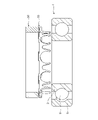
- a ball bearing 1 as shown in FIG. 34 is used to support a rotating portion of various rotating machines.
- the ball bearing 1 rolls between an inner ring 3 having an inner ring track 2 on the outer peripheral surface, an outer ring 5 arranged concentrically with the inner ring 3 and having an outer ring track 4 on the inner peripheral surface, and the inner ring track 2 and the outer ring track 4.
- It includes a plurality of balls 6 that are movably arranged.
- Each ball 6 is rotatably held by the cage 100. Further, the outer peripheral edges of the pair of annular shield plates 7 and 7 are locked to both ends of the inner peripheral surface of the outer ring 5 in the axial direction, respectively.
- the pair of shield plates 7 and 7 prevent a lubricant such as grease existing in the bearing space from leaking to the outside and dust floating on the outside from entering the bearing space.
- a contact type seal may be used instead of the non-contact type shield plates 7 and 7.
- the cage 100 is a resin crown type cage.
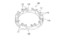
- the cage 100 is formed between an annular main portion 109, a plurality of pillar portions 110 projecting from the main portion 109 in the circumferential direction at predetermined intervals in the axial direction, and adjacent pillar portions 110, and forms a ball 6. It is provided with a spherical pocket 111 that can be held.
- the pillar portion 110 has a pair of claw portions 112, 112 whose tip portions are arranged at intervals from each other.
- the two adjacent claws 112 and 112 forming the pocket 111 hold the ball 6 to prevent the cage 100 from falling off from between the outer ring 5 and the inner ring 3 in the axial direction.
- FIGS. 34 to 36 stress acts on the cage 100 due to centrifugal force during high-speed rotation, and the cage 100 may be deformed to the outer diameter side.
- FIG. 34 the state in which the cage 100 is deformed is shown by a broken line.
- the cage 100 may come into contact with the outer ring 5 (see part A in FIG. 34), or the cage 100 may come into contact with the shield plate 7 (see part B in FIG. 34).
- the vessel 100 may wear, vibrate, or generate heat.
- Patent Document 1 and Patent Document 2 disclose techniques for reducing the weight of the cage.
- Patent Document 1 discloses that a slime portion is formed on an end surface of the crown type cage opposite to the end surface on the pocket forming portion side. This slimy portion improves the axial left-right mass balance of the crown-type cage and reduces the weight of the back side portion.
- the cage described in Patent Document 2 has an annular base portion and an axial portion extending in the axial direction from the base portion.
- the outer diameter of the axial portion is smaller than the outer diameter of the base portion.
- a hole penetrating in the axial direction is formed in the base portion so as to communicate with the recessed area of the axial portion.
- Patent Document 3 discloses that a protrusion is provided on the bottom surface of the back side of the pocket.
- Patent Document 4 states that in a cage for holding a ball of a bearing, the diameter of the circumscribed circle of each pocket constituting the cage should be equal to or less than the pitch circle diameter of a plurality of balls held in each pocket. It is disclosed. This prevents the tip of each convex portion constituting the cage from interfering with the inner peripheral surface of the outer ring even during high-speed rotation of the bearing, and reduces the material of the cage to reduce the manufacturing cost. I'm aiming.
- the material of the cage it is desirable to use a resin material containing, for example, a fibrous reinforcing agent, which is more rigid than the conventionally used polyamide 46 (PA46) and polyamide 66 (PA66). If the density of the rigid resin material does not change so much, the deformation of the cage due to centrifugal force can be suppressed according to the rate of improvement in rigidity.
- a resin material containing, for example, a fibrous reinforcing agent which is more rigid than the conventionally used polyamide 46 (PA46) and polyamide 66 (PA66). If the density of the rigid resin material does not change so much, the deformation of the cage due to centrifugal force can be suppressed according to the rate of improvement in rigidity.
- a rigid resin material that is, a material having a large flexural modulus (Young's modulus)
- Young's modulus generally has a low elongation in many cases. Therefore, not only is it difficult to deform during high-speed rotation, but it is also difficult to deform when a ball is assembled in the pocket of the cage, which may impair the life of the cage (particularly the claw portion).
- the present invention has been made in view of the above circumstances, and is a crown for ball bearings that reduces the strain generated in the cage when the ball is inserted into the pocket of the cage and makes it possible to use a highly rigid resin material.
- the primary purpose is to provide mold cages and ball bearings.
- the opening diameter of the pocket 111 of the conventional cage 100 is designed to be narrower than the diameter of the incorporated ball. Therefore, when the ball 6 is incorporated into the cage 100, the ball 6 is incorporated while expanding the pair of claw portions 112 of the cage 100 in the circumferential direction, so that an excessive strain is generated in the claw portion 112 of the cage 100. There was a possibility of shortening the life.
- the pocket opening diameter As a countermeasure, it is conceivable to design the pocket opening diameter to be widened so that the cage 100 is not damaged. However, in this design, it is necessary to set the pocket opening diameter wider as the elongation of the material used for the cage 100 becomes smaller. If the pocket opening diameter is made too wide, the cage 100 may come off from the ball 6 when subjected to axial vibration.
- Polyamides 6 and 6 or polyamides 4 and 6 are generally used for the crown type cage, but in an environment such as a high temperature region, PPS (polyphenylene sulfide) and PEEK (polyetheretherketone) are used. A material with low elongation is used.
- PPS polyphenylene sulfide
- PEEK polyetheretherketone
- the present invention has been made in view of the above circumstances, and a crown for ball bearings capable of incorporating a cage into a ball incorporated in a bearing without increasing the pocket opening diameter even if the material has a small elongation.
- a second object is to provide mold cages and ball bearings.
- cages are used to hold balls, but resin cages, especially crown-type cages, are used for the purpose of responding to higher rotation speeds of motor bearings due to electrification of automobiles and further reducing weight.
- the resin crown-shaped cage is formed between an annular main part, a plurality of pillars projecting from the main part in the circumferential direction at predetermined intervals in the axial direction, and adjacent pillars to hold balls. It has a possible pocket.
- the pillar portion has a pair of claw portions whose tips are arranged at intervals from each other. The two adjacent claws hold the ball to prevent the cage from falling off from between the outer ring and the inner ring in the axial direction.
- an entrance is provided that has a width shorter than the diameter of the ball and is for inserting into the ball. That is, the diameter of the inlet portion is designed to be narrower than the diameter of the ball to be inserted. Therefore, when the cage is incorporated into the bearing, the cage is inserted into the ball while expanding the claw portion of the cage in the circumferential direction. At this time, since the flat back surface of the cage is in surface contact with the lower pushing jig, etc., the portion where the cage can be deformed is exclusively the claw portion, and when the cage is inserted into the ball, the claw portion is formed. Excessive stress may be generated at the root, which may shorten the life of the cage.
- the insertion work of the cage is limited to the extent that the range of expanding the claws can be suppressed to the extent that the life of the cage can be suppressed.
- a third object of the present invention is to provide a crown type cage for ball bearings and a ball bearing into which a cage can be smoothly inserted.
- the above object of the present invention is achieved by the following configuration.
- (1) The main part of the ring and A plurality of pillars protruding in the axial direction at predetermined intervals in the circumferential direction from the main portion, A spherical pocket formed between the adjacent pillars and capable of holding a ball, A crown-type cage for ball bearings
- the pillar portion has a pair of claw portions whose tip portions are arranged at intervals from each other, and a connecting portion for connecting the pair of claw portions.
- a portion protruding in the axial direction is provided on the bottom surface of the main portion.
- a crown type cage for ball bearings made of resin.
- a first convex portion protruding in the axial direction is provided on the radial outer portion of the bottom surface of the main portion.
- the crown type cage for ball bearings according to (1), wherein at least a part of the first convex portion overlaps with the pocket in the circumferential direction and the radial direction.
- An entrance portion having a width shorter than the diameter of the ball and for inserting the ball is provided between the tips of the two adjacent claws constituting the pocket.
- the radius of curvature of the spherical concave surface of the pocket is larger than the radius of curvature of the rolling surface of the ball.
- the outer diameter D1 of the claw portion is smaller than the outer diameter D2 of the main portion.
- the radial width t1 of the claw portion is 1 ⁇ 2 or less of the radial width t2 of the main portion.
- the axial width H1 from the upper surface of the connecting portion of the column portion to the bottom surface of the main portion is 1 ⁇ 2 or less of the axial width H2 of the crown type cage for ball bearings (1) or (2).
- the crown type cage for ball bearings is 1 ⁇ 2 or less of the axial width H2 of the crown type cage for ball bearings (1) or (2).
- the crown type cage for ball bearings is 1 ⁇ 2 or less of the axial width H2 of the crown type cage for ball bearings (1) or (2).
- the crown type cage for ball bearings for ball bearings.
- a second convex portion protruding in the axial direction is provided on the bottom surface of the main portion. At least a part of the second convex portion overlaps with the pocket in the circumferential direction and the radial direction.
- the radial range and the circumferential range in which the second convex portion is provided are substantially the same as the radial range and the circumferential range in which the concave surface of the main portion constituting the pocket is provided.
- Crown type cage for ball bearings (7) The crown type cage for ball bearings according to any one of (1) to (6), wherein an opening is provided between the adjacent pockets in the main portion.
- the axial width H1 from the upper surface of the connecting portion of the pillar portion to the bottom surface of the main portion is larger than the axial width H3 of the main portion at the bottom of the pocket (1) to (7).
- the crown type cage for ball bearings according to any one. (9) The crown type for ball bearings according to any one of (1) to (8), wherein the radial width of the claw portion becomes smaller from the main portion side toward the tip end side of the claw portion. Cage. (10)
- the claw portion has a circumferential first surface constituting the pocket and a circumferential second surface opposite to the circumferential first surface. In the two adjacent claws constituting the pocket, the circumferential distance between the two circumferential second surfaces becomes smaller from the main portion side toward the tip end side of the claw portion (1).
- a pocket opening diameter shorter than the diameter of the ball is provided between the tips of two adjacent claws constituting the pocket, and the direction is opposite to one side in the axial direction.
- a pocket opening is provided for inserting the ball toward the other side in the axial direction.
- the portion that constitutes the pocket opening and that first comes into contact with the ball when it is inserted toward the other side in the axial direction is defined as the most advanced portion.
- the most advanced portion is located radially inside the radial center portion of the pocket, the bottom surface of the main portion has a diameter of the pocket as compared with the radially inside portion of the pocket radial center portion.
- the portion protrudes to the other side in the axial direction.
- the bottom surface of the main portion has a diameter of the pocket as compared with the radial outer portion of the pocket radial center portion.
- the entire tip end portion of the claw portion is arranged radially outside the radial center portion of the pocket.
- a convex portion projecting to the other side in the axial direction is provided on the bottom surface of the main portion.
- the entire cutting edge of the claw portion is arranged radially inside the central portion in the radial direction of the pocket.
- the bottom surface of the main portion is an inclined surface that protrudes to the other side in the axial direction from the inside in the radial direction to the outside in the radial direction.
- the bottom surface of the main portion is an inclined surface that protrudes to the other side in the axial direction from the outer side in the radial direction to the inner side in the radial direction.
- the most advanced portion is located at the outermost portion in the radial direction of the pocket opening by projecting the pocket opening to one side in the axial direction from the inner side in the radial direction to the outer side in the radial direction.
- the bottom surface of the main portion is an inclined surface that protrudes to the other side in the axial direction from the outer side in the radial direction to the inner side in the radial direction.
- the most advanced portion is located at the innermost portion in the radial direction of the pocket opening by projecting the pocket opening to one side in the axial direction from the outer side in the radial direction to the inner side in the radial direction.
- the bottom surface of the main portion is an inclined surface that protrudes to the other side in the axial direction from the inside in the radial direction to the outside in the radial direction.
- a convex portion projecting to the other side in the axial direction is provided on the bottom surface of the main portion.
- An entrance portion having a width shorter than the diameter of the ball and for inserting the ball is provided between the tip portions of the two claw portions adjacent to each other across the pocket.
- At least one projecting portion is formed so as to project axially from the bottom surface of the main portion at a position corresponding to the pocket in the circumferential direction.
- the crown type cage for ball bearings according to (1) which is made of resin.
- the bottom surface faces the other facing member, and the bottom surface faces the other facing member.
- the axially protruding height of the protruding portion is smaller than the axial distance from the bottom surface to the other opposing member.
- the protrusion is formed at a position on the center line of the pocket in the circumferential direction.
- a plurality of the protrusions are formed symmetrically with respect to the center line at a position deviated from the position on the center line of the pocket in the circumferential direction.
- the crown type cage for ball bearings according to (25) or (26).
- the bottom surface faces the other facing member, and the bottom surface faces the other facing member.
- the center line of the two bottom surface intermediate positions P2 of the bottom surface in which the pocket is located on the intermediate position between each of the other two adjacent pockets in the circumferential direction and the center line of the pocket in the circumferential direction of the other facing member.
- the center position P3 of the opposite member to be located is defined,
- the tip of the protrusion is located in a region surrounded by a line segment P2-P2 and two line segments P2-P3 in the circumferential direction.
- the crown type cage for ball bearings according to any one of (25) to (28).
- the protruding portion is formed in a region having a width of the entrance portion in the circumferential direction.
- An entrance portion having a width shorter than the diameter of the ball and for inserting the ball is provided between the tip portions of the two claw portions adjacent to each other across the pocket.
- At least two inclined surfaces that are inclined in the axial direction are formed on the bottom surface of the main portion, and the two inclined surfaces intersect to form a top.
- the crown type cage for ball bearings according to (1) which is made of resin. (32) When the crown type cage for ball bearings is used, the bottom surface faces the other facing member, and the bottom surface faces the other facing member.
- the inclined surface is defined between the top and the bottom that is the farthest in the axial direction from the top.
- the axial height of the inclined surface is smaller than the axial distance from the bottom to the other opposing member.
- the top is formed at a position on the center line of the pocket in the circumferential direction.
- the crown type cage for ball bearings according to any one of (1) to (34) which is composed of a resin composition containing polyamide 9T and a fibrous reinforcing material.
- the strain generated in the cage when the balls are inserted into the pockets of the cage can be reduced, and thus the strain is conventionally used in the cage. It is possible to use a highly rigid resin material, which has been difficult to achieve.
- FIG. 19 is a cross-sectional view taken along the line AA of FIG.
- FIG. 19 is a cross-sectional view taken along the line BB of FIG.
- FIG. 9 is a cross-sectional view taken along the line EE of FIG. 39. It is a figure which saw a part of the cage which concerns on 4th Embodiment from the outside in the radial direction.
- FIG. 7 It is a figure which shows the mode that the cage of the 7th Embodiment is incorporated in a bearing.
- A shows the cage of the seventh embodiment
- (b) to (c) are diagrams showing the strain generated in the cage when the cage of the seventh embodiment is incorporated in the bearing.
- B is a view of the cage viewed from the circumferential direction
- (c) is a view of the cage viewed from one side (upper side) in the axial direction.
- A) shows the cage of the comparative example
- (b) to (c) are diagrams showing the strain generated in the cage when the cage of the comparative example is incorporated in the bearing.
- (B) is a view of the cage viewed from the circumferential direction
- (c) is a view of the cage viewed from one side (upper side) in the axial direction.
- FIG. 71 shows the process of inserting a ball between a pair of claws of a crown type cage for ball bearings from the state of FIG. 71.
- the ball bearing crown type cage 10 of the present embodiment is the conventional crown type cage shown in FIGS. 35 to 36. Similar to the cage 100, it can be applied to the ball bearing 1 shown in FIG. 34.
- a polyamide resin such as polyamide 46 or polyamide 66
- a resin such as polybutylene terephthalate, polyphenylene sulfide (PPS), polyether ether ketone (PEEK), or polyether nitrile (PEN).
- PPS polyphenylene sulfide
- PEEK polyether ether ketone
- PEN polyether nitrile
- a resin material having a higher flexural modulus than that of the polyamide 46 or the polyamide 66 can be used.
- the cage 10 may be composed of a resin composition containing polyamide 9T (PA9T) and a fibrous reinforcing material.
- the fibrous reinforcing material is preferably carbon fiber having a fiber diameter of 6 ⁇ m or more and 8 ⁇ m or less, which is added to the resin composition at a ratio of 15% by mass or more and 35% by mass or less.
- As the carbon fiber it is preferable to use a PAN-based carbon fiber obtained by firing acrylonitrile fiber.
- Polyamide 9T can be obtained by adding carbon fiber "Treca (registered trademark) middle fiber" of Toray Industries, Inc. to PA9T "Genesta (registered trademark)” of Kuraray Industries, Ltd.
- the cage 10 may be composed of a resin composition containing a polyamide 10T (PA10T) and a fibrous reinforcing material.
- the fibrous reinforcing material is a glass fiber having a fiber diameter of 6 ⁇ m or more and 13 ⁇ m or less added in a ratio of 20% by mass or more and 50% by mass or less in the resin composition, or 20% by mass or more and 35% by mass in the resin composition. It is preferable that the carbon fibers have a fiber diameter of 5 ⁇ m or more and 9 ⁇ m or less added in the following proportions.
- the cage 10 preferably contains at least one of copper iodide and potassium iodide as an iodide-based heat stabilizer.
- the polyamide 10T one containing glass fiber of "XecoT (registered trademark)" of Unitika Ltd. can be used.
- Examples of the method for manufacturing the cage 10 include a method of injection molding using a mold and a method of manufacturing with a 3D printer.
- an annular cavity corresponding to the cage for the bearing, which is a molded body, is formed in the molding mold, and the resin material (heat) melted from the resin injection gate provided at the peripheral edge of this cavity.
- the cage 10 is manufactured by injecting (plastic resin) and cooling and solidifying the resin material.
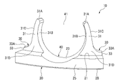
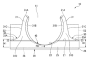
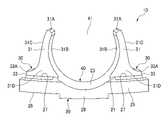
- the crown type cage 10 is formed between an annular main portion 20, a plurality of pillar portions 30 projecting from the upper surface 21 of the main portion 20 in the circumferential direction at predetermined intervals, and adjacent pillar portions 30, 30. It is provided with a spherical pocket 40, which is formed in a shape and can hold a ball 6 (see FIG. 34).
- a plurality of spherical concave surfaces 23 are formed on the upper surface 21 of the main portion 20 at predetermined intervals in the circumferential direction.
- the concave surface 23 is formed over the entire radial width of the main portion 20 and constitutes the pocket 40.
- the pillar portion 30 projects axially from the radial inner portion of the upper surface 21 of the main portion 20. Therefore, the upper surface 21 of the main portion 20 is exposed on the radial outer side of the pillar portion 30.
- the pillar portion 110 projects in the axial direction from the entire radial width of the upper surface of the main portion 109, so that the pillar portion 30 of the present application differs in this respect. That is, in the present application, a configuration is adopted in which the radial outer region (region S1 shown by the broken line in FIG. 4) of the pillar portion 30 (claw portion 31) is cut off.
- the pillar portion 30 has a pair of claw portions 31, 31 and a connecting portion 33 connecting the pair of claw portions 31, 31.
- the tip portions 31A, 31A of the pair of claw portions 31, 31 are arranged so as to be spaced apart from each other in the circumferential direction. Further, between the tip portions 31A and 31A of the two adjacent claw portions 31 and 31 constituting the pocket 40, the width is shorter than the diameter of the ball 6 (see FIG. 34), and the ball 6 is inserted. An entrance 41 is provided for insertion.
- the claw portion 31 has a spherical first surface 31B forming the pocket 40 and a circumferential second surface 31C opposite to the circumferential first surface 31B.
- the second peripheral surfaces 31C and 31C of the pair of claw portions 31 and 31 have curved shapes, respectively, and are smoothly connected by the upper surface 33A of the connecting portion 33.
- the upper surface 33A of the connecting portion 33 corresponds to a substantially U-shaped bottom portion formed by the pair of circumferential second surfaces 31C and 31C.
- the upper surface 33A (the bottom of the pair of circumferential second surfaces 31C and 31C) of the connecting portion 33 is located slightly above the upper surface 21 of the main portion 20 (on one side in the axial direction) (see FIG. 4). Therefore, the bottom portion (upper surface 33A of the connecting portion 33) of the pair of circumferential second surfaces 31C and 31C is located relatively downward (the other side in the axial direction), and forms a substantially U-shaped recess.
- the upper surface of the connecting portion (the bottom portion of the pair of circumferential second surfaces) is located considerably above the upper surface of the main portion 109. That is, in the present application, a configuration is adopted in which the region (region S2 shown by the broken line in FIG. 2) sandwiched between the pair of claw portions 31, 31 in the circumferential direction second surfaces 31C, 31C is cut off.
- the circumferential first surfaces 31B and 31B of the two adjacent claw portions 31 and 31 and the concave surface 23 of the main portion 20 form a pocket 40. These two circumferential first surfaces 31B and 31B and the concave surface 23 are smoothly connected to each other to form a spherical concave surface of the pocket 40.
- the radius of curvature of the spherical concave surface of the pocket 40 is set to be larger than the radius of curvature of the rolling surface of the ball 6 (see FIG. 34).
- the cage 10 since the plurality of pockets 40 are connected by the main portion 20, when a centrifugal force is applied to the cage 10 at the time of high-speed rotation or the like, the cage 10 is radially outward around the main portion 20. Trying to fall. In order to suppress this collapse, in the present application, the regions S1 and S2 are cut off as described above.
- the centrifugal force is F
- the mass is m
- the distance from the axis of rotation to the rotating object (retainer 10) is r
- the angular velocity is ⁇
- F mr ⁇ 2 .
- the stress ⁇ generated in the cage 10 (particularly the bottom of the pocket 40) and the deformation amount ⁇ of the cage 10 are substantially proportional to the centrifugal force F. Therefore, when the axial width of the ball bearing 1, the inner diameter of the inner ring 3, and the outer diameter of the outer ring 5 are constant, it is necessary to reduce the mass m of the cage 10 in order to reduce the stress ⁇ and the amount of deformation ⁇ . .. Further, since the deformation amount ⁇ of the cage 10 is substantially inversely proportional to the rigidity of the cage 10, if the shape of the cage 10 does not change, the rigidity of the cage 10, that is, Young's modulus may be increased.
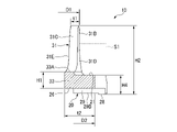
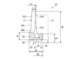
- the outer diameter D1 of the claw portion 31 is set smaller than the outer diameter D2 of the main portion 20. That is, the outer peripheral surface 31D of the claw portion 31 (pillar portion 30) is located inward by (D2-D1) in the radial direction from the outer peripheral surface 25 of the main portion 20.
- the inner peripheral surface 31E of the claw portion 31 (pillar portion 30) is smoothly connected to the inner peripheral surface 24 of the main portion 20 to form an inner peripheral surface of the cage 10 having no step.
- the radial width t1 of the claw portion 31 is set to 1/2 or less of the radial width t2 of the main portion 20.
- the axial width H1 from the upper surface 33A of the connecting portion 33 of the pillar portion 30 to the bottom surface 26 of the main portion 20 is set to 1/2 or less of the axial width H2 of the cage 10.
- the axial width H1 is made too small, the strength of the cage 10 may decrease, or when the cage 10 is manufactured by injection molding, the resin may not flow and voids may occur.
- the radial width of each portion of the cage 10 is preferably 1 mm or more. Therefore, the axial width H1 is preferably larger than the axial width H3 (see FIG. 2) of the main portion 20 at the bottom of the pocket 40 (H1> H3), and the pocket 40 (concave surface 23) of the main portion 20 is formed. It is more preferable to make the width of the non-formed portion larger than the axial width H4 (see FIG. 4) (H1> H4).
- the axial width H3 is the distance between the lowermost surface of the concave surface 23 of the pocket 40 and the bottom surface 26 of the main portion 20. That is, the axial width H3 is the axial width of the portion of the main portion 20 having the shortest axial width. As described above, it is preferable that the dimensional relationship in the axial direction satisfies H3 ⁇ H4 ⁇ H1 ⁇ (H2 / 2).
- the weight of the cage 10 can be reduced and deformation can be suppressed. Therefore, it is possible to prevent the cage 10 from coming into contact with the outer ring 5, the shield plate 7, and the like, and it is possible to suppress wear, vibration, and heat generation of the cage 10.
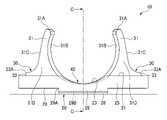
- the bottom surface 26 of the main portion 20 of the cage 10 is provided with a portion protruding in the axial direction. .. More specifically, the bottom surface 26 is provided with a first convex portion 28 projecting in the axial direction.
- the first convex portion 28 projects in the axial direction (the direction opposite to the direction in which the claw portion 31 extends) from the radial outer portion of the bottom surface 26 of the main portion 20.
- the first convex portion 28 of the present embodiment is provided on the outer side portion in the radial direction of the bottom surface 26 of the main portion 20 over the entire circumference.
- the radial width t4 of the first convex portion 28 is set to be relatively smaller than the radial width t2 of the bottom surface 26 of the main portion 20, and the first convex portion 28 is set.
- the claw portion 31 do not overlap in the radial direction.
- the claw portion 31 falls inward in the radial direction, so that the entire claw portion 31 constituting the pocket 40 spreads uniformly and is generated in the cage 10.
- the strain (stress) to be applied can be reduced.
- the ball 6 is inserted into the pocket 40 of the cage 10", but more accurately, the ball 6 is inserted into each pocket 40 of the cage 10.
- the cage 10 is incorporated into the ball bearing 1 by fitting the cage 10 into a plurality of balls 6 arranged between the inner ring 3 and the outer ring 5 of the ball bearing 1.
- the description is for convenience.
- the first convex portion 28 does not necessarily have to be provided over the entire circumference of the bottom surface 26 of the main portion 20, and at least a part of the first convex portion 28 overlaps the pocket 40 in the circumferential direction and the radial direction (axis). It may be provided at a position where it overlaps with the pocket 40 when viewed from the direction). In this case, it is preferable that the plurality of first convex portions 28 are provided at positions overlapping the pocket 40 in the circumferential direction and the radial direction (positions overlapping the pocket 40 when viewed from the axial direction) at predetermined intervals in the circumferential direction. ..
- (Second Embodiment) 6 to 9 disclose the cage 10 according to the second embodiment.
- the cage 10 of the present embodiment is different from the cage 10 of the first embodiment in that the main portion 20 is provided with the opening 27. Since the other configurations are the same as those in the above embodiment, the description thereof will be omitted by adding reference numerals to the drawings.
- the main portion 20 is provided with an opening 27 between adjacent pockets 40 and 40.
- the opening 27 penetrates the bottom surface 26 from the top surface 21 of the main portion 20 in the axial direction.
- the opening 27 is located radially outside the pillar 30 (a pair of claws 31, 31). That is, at least a part of the opening 27 overlaps with the pillar portion 30 (a pair of claw portions 31, 31) in the circumferential direction.
- the peripheral wall portion of the illustrated opening 27 is composed of a stepped surface, a tapered surface, and the like, but the shape thereof is not particularly limited.
- the cage 10 can be easily removed from the mold during injection molding as compared with the case where the opening 27 is composed of a simple flat surface. ..
- the radial width t3 (see FIG. 8) of the opening 27 becomes too large, the radial width of the other portion of the cage 10 (for example, the radial width t4 of the first convex portion 28) becomes small and the strength becomes high.
- the width of each portion of the cage 10 is preferably 1 mm or more. Therefore, the radial width t3 of the opening 27 is preferably about (t2 / 3) ⁇ t3 ⁇ (t2 / 2) with respect to the radial width t2 of the main portion 20.
- the weight of the cage 10 can be reduced and deformation can be suppressed. Therefore, it is possible to prevent the cage 10 from coming into contact with the outer ring 5, the shield plate 7, and the like, and it is possible to suppress wear, vibration, and heat generation of the cage 10.
- FIGS. 10 to 13 disclose the cage 10 according to the third embodiment.
- the cage 10 of the present embodiment is different from the cage 10 of the first embodiment in that the second convex portion 29 is provided on the bottom surface 26 of the main portion 20. Since the other configurations are the same as those in the first embodiment, the description thereof will be omitted by adding reference numerals to the drawings.
- the bottom surface 26 of the main portion 20 is provided with a second convex portion 29 that protrudes in the axial direction (the direction opposite to the direction in which the claw portion 31 extends).
- the second convex portion 29 is provided so that at least a part thereof overlaps with the pocket 40 in the circumferential direction and the radial direction. That is, the bottom surface 26 of the main portion 20 has a plurality of second convex portions 29 formed at predetermined intervals in the circumferential direction below the plurality of pockets 40.
- the second convex portion 29 preferably overlaps the pocket 40 in the circumferential direction and the radial direction. That is, it is preferable that the circumferential range and the radial range in which the second convex portion 29 is provided are substantially the same as the circumferential range and the radial range in which the concave surface 23 of the main portion 20 constituting the pocket 40 is provided.
- the radial width t5 and the circumferential width L2 of the second convex portion 29 are the radial width (radial width t2 of the main portion 20) and the circumferential width L1 of the concave surface 23 of the main portion 20 constituting the pocket 40. Is almost the same as.
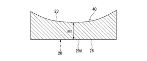
- the shortest distance between the root portions 29A at both ends of the second convex portion 29 in the circumferential direction and the concave surface 23 of the main portion 20 constituting the pocket 40 is M1
- the second convex portion 29 Assuming that the shortest distance between the tip surface (bottom surface) 29B and the concave surface 23 is M2, it is preferable that M1> M2. This is because if the shortest distance M1 is reduced, the stress generated in the pocket 40 due to the centrifugal force becomes higher in the concave surface 23 in the cross section A than in the concave surface 23 in the cross section B shown in FIG.
- first convex portion 28 of the present embodiment further projects in the axial direction (direction opposite to the direction in which the claw portion 31 extends) from the tip surface (bottom surface) 29B of the second convex portion 29. That is, the first convex portion 28 does not extend directly from the bottom surface 26 of the main portion 20, but extends from the tip surface (bottom surface) 29B of the second convex portion 29 provided on the bottom surface 26 of the main portion 20. It can be said that the second convex portion 29 is provided between the first convex portion 28 and the bottom surface 26 of the main portion 20.
- the first convex portion 28 is provided on the radial outer peripheral side of the tip surface (bottom surface) 29B of the second convex portion 29.
- the radial width t4 of the first convex portion 28 is smaller than the radial width t5 of the second convex portion 29. Further, the circumferential width of the first convex portion 28 and the circumferential width of the second convex portion 29 are substantially the same.
- the fulcrum is from the tip 31A of the claw portion 31, the wider the range in which the strain is generated (the strain is dispersed), and the less the strain is generated in the claw portion 31.
- the first convex portion 28 which serves as a fulcrum for the deformation of the claw portion 31, is twisted from the tip portion 31A of the claw portion 31. It can be positioned far away, and the strain generated in the claw portion 31 can be reduced.
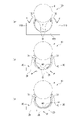
- FIG. 33 (a) to 33 (c) are views showing a strain generation region when the ball is incorporated into the cage, (a) shows the cage 100 of the conventional example, and (b) is the cage 10 of the comparative example. (C) shows the cage 10 of the third embodiment.
- the cage 10 of the comparative example of FIG. 33 (b) is different from the cage 10 of the third embodiment of FIG. 33 (c) in that the first convex portion 28 is not provided on the second convex portion 29.
- the strain region (strain generation region D) generated in the claw portion 112 becomes narrow and strain. Becomes larger.
- the strain generation region D is widened and the strain is lower than that of the conventional example.
- the strain generation region D is further widened, and the strain is further reduced as compared with the comparative example.
- (Fourth Embodiment) 14 to 21 disclose the cage 10 according to the fourth embodiment.
- the cage 10 of the present embodiment is different from the first embodiment in that the main portion 20 is provided with the opening 27 and the bottom surface 26 of the main portion 20 is provided with the second convex portion 29.
- the cage 10 of the present embodiment has a configuration in which the configuration of the cage 10 of the second embodiment (opening 27) and the configuration of the cage 10 of the third embodiment (second convex portion 29) are combined. Have.
- the main portion 20 is provided with an opening 27 between adjacent pockets 40 and 40.
- the opening 27 penetrates the bottom surface 26 from the top surface 21 of the main portion 20 in the axial direction.
- the opening 27 is located radially outside the pillar 30 (a pair of claws 31, 31). That is, at least a part of the opening 27 overlaps with the pillar portion 30 (a pair of claw portions 31, 31) in the circumferential direction.
- the peripheral wall portion of the illustrated opening 27 is composed of a stepped surface, a tapered surface, and the like, but the shape thereof is not particularly limited.
- the radial width t3 (see FIG. 17) of the opening 27 becomes too large, the radial width of the other portion of the cage 10 (for example, the radial width t4 of the first convex portion 28) becomes small and the strength becomes high.
- the width of each portion of the cage 10 is preferably 1 mm or more. Therefore, the radial width t3 of the opening 27 is preferably about (t2 / 3) ⁇ t3 ⁇ (t2 / 2) with respect to the radial width t2 of the main portion 20.
- the weight of the cage 10 can be reduced and deformation can be suppressed. Therefore, it is possible to prevent the cage 10 from coming into contact with the outer ring 5, the shield plate 7, and the like, and it is possible to suppress wear, vibration, and heat generation of the cage 10.
- the bottom surface 26 of the main portion 20 is provided with a second convex portion 29 that protrudes in the axial direction (the direction opposite to the direction in which the claw portion 31 extends).
- the second convex portion 29 is provided so that at least a part thereof overlaps with the pocket 40 in the circumferential direction and the radial direction. That is, the bottom surface 26 of the main portion 20 has a plurality of second convex portions 29 formed at predetermined intervals in the circumferential direction below the plurality of pockets 40.
- the second convex portion 29 preferably overlaps the pocket 40 in the circumferential direction and the radial direction. That is, it is preferable that the circumferential range and the radial range in which the second convex portion 29 is provided are substantially the same as the circumferential range and the radial range in which the concave surface 23 of the main portion 20 constituting the pocket 40 is provided.
- the radial width t5 and the circumferential width L2 of the second convex portion 29 are the radial width (radial width t2 of the main portion 20) and the circumferential width L1 of the concave surface 23 of the main portion 20 constituting the pocket 40. Is almost the same as.
- the shortest distance between the root portions 29A at both ends of the second convex portion 29 in the circumferential direction and the concave surface 23 of the main portion 20 constituting the pocket 40 is M1, and the second convex portion 29.
- M1 the shortest distance between the tip surface (bottom surface) 29B and the concave surface 23
- M1> M2 it is preferable that M1> M2. This is because if the shortest distance M1 is reduced, the stress generated in the pocket 40 due to the centrifugal force becomes higher in the concave surface 23 in the cross section A than in the concave surface 23 in the cross section B shown in FIG.
- first convex portion 28 of the present embodiment further projects in the axial direction (direction opposite to the direction in which the claw portion 31 extends) from the tip surface (bottom surface) 29B of the second convex portion 29. That is, the first convex portion 28 does not extend directly from the bottom surface 26 of the main portion 20, but extends from the tip surface (bottom surface) 29B of the second convex portion 29 provided on the bottom surface 26 of the main portion 20. It can be said that the second convex portion 29 is provided between the first convex portion 28 and the bottom surface 26 of the main portion 20.
- the first convex portion 28 is provided on the outer peripheral side in the radial direction of the tip surface 29B of the second convex portion 29.
- the radial width t4 of the first convex portion 28 is smaller than the radial width t5 of the second convex portion 29. Further, the circumferential width of the first convex portion 28 and the circumferential width of the second convex portion 29 are substantially the same.
- the fulcrum is from the tip 31A of the claw portion 31, the wider the range in which the strain is generated (the strain is dispersed), and the less the strain is generated in the claw portion 31.
- the first convex portion 28 which serves as a fulcrum for the deformation of the claw portion 31, is twisted from the tip portion 31A of the claw portion 31. It can be positioned far away, and the strain generated in the claw portion 31 can be reduced.
- FIG. 22 discloses the cage 10 according to the fifth embodiment.
- the cage 10 of the present embodiment is different from the cage 10 of the above embodiment in the radial dimension of the claw portion 31. Since the other configurations are the same as those in the fourth embodiment, the description thereof will be omitted by adding reference numerals to the drawings.
- the radial width of the claw portion 31 becomes smaller from the main portion 20 side toward the tip portion 31A side of the claw portion 31. That is, the relationship between the radial widths a1, a2, and a3 of the claw portion 31 in FIG. 22 satisfies a1 ⁇ a2 ⁇ a3.
- the stress and strain generated in the claw portion 31 can be reduced. This is particularly effective when the tip portion 31A of the claw portion 31 receives a force from the ball 6. Further, when the cage 10 is injection-molded, it is effective because the cage 10 can be easily removed from the mold.
- the relationship between the radial widths a1, a2, and a3 of the claw portion 31 is a1 ⁇ a2 ⁇ a3.
- the present invention is not limited to this configuration. That is, in the cage 10 of the first to third embodiments, the relationship between the radial widths a1, a2, and a3 of the claw portion 31 may be configured to satisfy a1 ⁇ a2 ⁇ a3.
- FIG. 23 discloses the cage 10 according to the sixth embodiment.
- the cage 10 of the present embodiment is different from the cage 10 of the fourth embodiment in the circumferential distance between the circumferential second surfaces 31C and 31C of the two adjacent claws 31 and 31 constituting the pocket 40. .. Since the other configurations are the same as those in the above embodiment, the description thereof will be omitted by adding reference numerals to the drawings.
- the circumferential distance between the two circumferential second surfaces 31C and 31C is the claw from the main portion 20 side. It becomes smaller toward the tip portion 31A of the portion 31. That is, the relationship of the circumferential distances b1, b2, b3 between the circumferential second surfaces 31C, 31C of the two adjacent claw portions 31, 31 in FIG. 23 satisfies b1 ⁇ b2 ⁇ b3.
- the stress and strain generated in the claw portion 31 can be reduced. This is particularly effective when the tip portion 31A of the claw portion 31 receives a force from the ball 6. Further, when the cage 10 is injection-molded, it is effective because the cage 10 can be easily removed from the mold.
- the relationship between the circumferential distances b1, b2, and b3 satisfies b1 ⁇ b2 ⁇ b3.
- the present invention is not limited to the configuration. That is, in the cages 10 of the first to third and fifth embodiments, the relationship between the circumferential distances b1, b2, and b3 may be configured to satisfy b1 ⁇ b2 ⁇ b3.
- the cage 10 to be analyzed is a crown resin cage used for bearings having an inner diameter of 35 mm.
- the shape was set based on the embodiment of the present invention based on the conventional crown type resin cage.
- the cage 10 of the fourth embodiment shown in FIGS. 14 to 21 was adopted, and as a comparative example, the cage 10 shown in FIGS. 24 to 27 was adopted.
- the cage 10 of the comparative example is different from the cage 10 of the embodiment (fourth embodiment) in that it does not have the first convex portion 28.
- the configuration other than the first convex portion 28 is the same in the comparative example and the embodiment.
- the inner diameter of the cage 10 is 49 mm
- the maximum outer diameter of the main portion 20 is 58 mm
- the axial height of the cage 10 is 10 mm including the first convex portion 28, and the pillar portion 30.
- the axial thickness H1 of the connecting portion 33 of the above is set to 3 mm (in the conventional example as shown in FIGS. 35 and 36, it is about 7 mm).
- the radial width of the tip 31A of the claw portion 31 is 1.2 mm
- the radial width of the opening 27 of the main portion 20 is 2 mm
- the axial width of the second convex portion 29 (from the bottom surface 26 of the main portion 20 to the second convex).
- the distance of the portion 29 to the tip surface 29B) was 0.9 mm
- the axial width of the first convex portion 28 was 0.2 mm
- the radial width of the first convex portion 28 was 1.1 mm.
- the axial height of the cage 10 is 10 mm, and the other dimensions are the same as those of the cage 10 of the embodiment having the first convex portion 28. did.
- the strain became maximum when the center of the ball 6 reached the tip portion 31A (entrance portion 41 of the pocket 40) of the claw portion 31 of the cage 10.
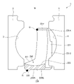
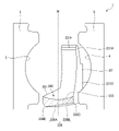
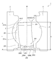
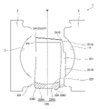
- FIG. 31 which is a cross-sectional view taken along the line DD of FIG. 25
- the cage 10 of the comparative example has a claw portion 31 that is curved in a bow
- the cage portion 31 is a cross-sectional view taken along the line CC of FIG.
- the claw portion 31 of the cage 10 of the embodiment does not follow the bow.
- the deformation magnification of the shown figure was set to 10 times.
- the strain is reduced by providing the first convex portion 28. Assuming that the maximum strain generated in the claw portion 31 of the cage 10 of the comparative example is 1.0, the maximum strain generated in the claw portion 31 of the cage 10 of the example is 0.9, which is a decrease of 10%.
- the cage 10 of each embodiment is incorporated into a ball bearing 1 in which a plurality of balls 6 are already incorporated between the outer ring 5 and the inner ring 3 by using a jig 50.
- the jig 50 has a ring shape.
- the inner and outer diameters of the jig 50 are substantially equal to the inner and outer diameters of the cage 10, and the cage 10 can be urged in the axial direction toward the ball bearing 1.
- FIG. 38 shows a state in which the cage 10 is incorporated in the ball bearing 1.
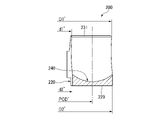
- FIG. 39 is a perspective view of a part of the cage 200 according to the comparative example
- FIG. 40 is a cross-sectional view taken along the line EE of FIG. 39.
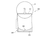
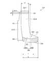
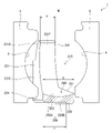
- the cage 200 is a crown-type cage, and has an annular main portion 220, a plurality of pillar portions 230 projecting from the upper surface of the main portion 220 in the circumferential direction at predetermined intervals, and adjacent pillar portions 230. , A spherical pocket 240 formed between 230 and capable of holding a ball.
- the pillar portion 230 protrudes in the axial direction from the entire radial width of the upper surface of the main portion 220.
- the pillar portion 230 has a pair of claw portions 231 and 231 and a connecting portion 233 that connects the pair of claw portions 231 and 231.
- a convex portion 229 that protrudes in the axial direction (the direction opposite to the direction in which the claw portion 231 extends) is provided.
- the convex portion 229 overlaps the pocket 240 in the circumferential direction and the radial direction. That is, the circumferential range and the radial range in which the convex portion 229 is provided are substantially the same as the circumferential range and the radial range in which the pocket 240 is provided. Therefore, the convex portion 229 corresponds to the second convex portion 29 of each embodiment of the present application.
- the cage 200 does not include a cage 28 corresponding to the first convex portion 28 of each embodiment of the present application.
- the outer diameter of the main portion 220 is indicated by D2'
- the inner diameter of the main portion is indicated by d2'
- the outer diameter of the claw portion 231 is indicated by D1'
- the inner diameter of the claw portion is indicated by d1'.
- FIGS. 41 to 43 show how the cage 10 of the fourth embodiment is incorporated into the ball 6 by the jig 50.
- FIG. 41 is a view of a part of the cage 10 according to the fourth embodiment as viewed from the outside in the radial direction.
- FIG. 42 is a partial cross-sectional view of a part of the cage 10 according to the fourth embodiment as viewed from the circumferential direction.
- FIG. 43 is a view of a part of the cage 10 according to the fourth embodiment as viewed from the upper surface side. In FIGS. 41 to 43, the inner ring 3 and the outer ring 5 are not shown.
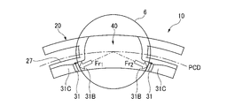
- FIGS. 41 to 43 show the force applied to the first surface 31B in the circumferential direction of the pair of claws 31 constituting the pocket 40 when the ball 6 is inserted into the pocket 40. Since the ball 6 is incorporated between the outer ring 5 and the inner ring 3, it can hardly move in the radial direction. When the balls 6 start to come into contact with the tips of the pair of claws 31, as shown in FIG. 41, the forces in the normal direction are applied to the circumferential first surfaces 31B forming the pockets 40 of the pair of claws 31, respectively. F 1 and F 2 are applied. In FIGS. 42 and 43, the forces F 1 and F 2 are divided into the axial component forces Fz 1 and Fz 2 in the axial direction (vertical direction in FIG.
- the component force Fz 1 applies a force from the tip of the claw portion 31 toward the bottom of the pocket 40. Although not shown, the same applies to the component force Fz 2 .
- FIG. 43 shows the component forces Fr 1 and Fr 2 in the axial direction of the forces F 1 and F 2 .
- the first surface 31B in the circumferential direction of the claw portion 31 has a spherical shape in most parts, and has a cylindrical surface shape in the vicinity of the tip of the claw portion 31. Therefore, the first surface 31B in the circumferential direction of the claw portion 31 has an arcuate cross-sectional shape perpendicular to the axial direction, and is concentric with the center position of the ball 6. Therefore, the direction in which the forces Fr 1 and Fr 2 are applied is the normal direction of the first surface 31B in the circumferential direction of the claw portion 31, and the forces Fr 1 and Fr 2 pass through the central position of the ball 6.
- the first convex portion 28 is provided on the outer side in the radial direction
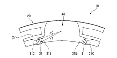
- the claw portion 31 is provided on the inner side in the radial direction. Therefore, when the axial component force Fz 1 is applied to the claw portion 31 as shown in FIG. 42, the claw portion 31 uses the inner peripheral edge of the first convex portion 28 in contact with the jig 50 as a fulcrum P. A moment M acts in the direction in which the jig is about to fall toward the inner circumference.
- the cage 10 of the present application is made of resin, and the axial thickness of the main portion 20 is sufficiently thinner than the radial width. Therefore, when the axial forces Fz 1 and Fz 2 are applied to the claw portion 31, the main portion 20 is twisted and elastically deformed, and as shown in FIG. 44, the main portion 20 is inclined inward in the radial direction.
- the cage 10 after elastic deformation is shown by a solid line, and the cage 10 before elastic deformation is shown by a broken line.
- the claw portion 31 is also tilted inward in the radial direction.
- the radial width t1 of the claw portion 31 of the cage 10 of the present application is 1 ⁇ 2 or less of the radial width t2 of the main portion 20 (see FIG. 18), and the claw portion 31 is larger than the pitch circle diameter PCD of the cage 10. It is arranged radially inside. Therefore, when the claw portion 31 is tilted inward in the radial direction, as shown in FIG. 45, the radius r0 of the entrance portion of the narrowest pocket 40 formed by the tip of the claw portion 31 expands as if it were r1.
- the cage 10 after elastic deformation is shown by a solid line
- the cage 10 before elastic deformation is shown by a broken line.
- the ball 6 When the ball 6 further moves in the axial direction and is inserted into the pocket 40, the ball 6 is incorporated between the outer ring 5 and the inner ring 3, so that the ball 6 can hardly move in the radial direction. Therefore, since the radius of the entrance portion of the pocket 40 is widened to r1, the amount of laterally expanding the claw portion 31 by the component forces Fr 1 and Fr 2 (see FIG. 43) in the axial direction is small. , The strain and stress generated in the claw portion 31 are reduced.
- FIGS. 46 to 48 show how the cage 200 of the comparative example is incorporated in the ball 6.
- FIG. 46 is a view of a part of the cage 200 according to the comparative example as viewed from the outside in the radial direction.
- FIG. 47 is a partial cross-sectional view of a part of the cage 200 according to the comparative example as viewed from the circumferential direction.
- FIG. 48 is a view of a part of the cage 10 according to the comparative example as viewed from the upper surface side.
- FIGS. 46 to 48 show the force applied to the inner peripheral surfaces of the pair of claw portions 231 constituting the pocket 240 when the ball 6 is inserted into the pocket 240. Since the ball 6 is incorporated between the outer ring 5 and the inner ring 3, it can hardly move in the radial direction. When the ball 6 starts to come into contact with the tips of the pair of claws 231 and as shown in FIG. It takes.
- the forces F1 and F2 are divided into axial component forces F z1 and F z2 , respectively (vertical direction in FIG. 47), and axial component forces F r1 and F r2 , respectively. Is shown. Since only one of the pair of claw portions 231 is shown in FIG. 47, only the component force F z1 of F1 is shown among the forces F z1 and F z2 in the axial direction, and the component force of F2 is shown. F z2 is not shown.
- the component force F z1 is applied with a force from the tip of the claw portion 31 toward the bottom of the pocket 40. Although not shown, the same applies to the component force F z2 .
- the cage 10 of the fourth embodiment does not have the first convex portion 28 will be considered. That is, the cage 10 of the comparative example is provided with the second convex portion 29, but the second convex portion 29 is not provided with the first convex portion 28.
- FIG. 49 is a view of a part of the cage 10 according to the comparative example from the inside in the radial direction.
- FIG. 50 is a partial cross-sectional view of a part of the cage 10 according to the comparative example as viewed from the circumferential direction.
- FIG. 51 is a view of a part of the cage 10 according to the comparative example as viewed from the upper surface side.
- the ball 6 when it starts to come into contact with the tip of the claw portion 31 is shown by a broken line
- the ball 6 when it enters the entrance of the pocket 40 is shown by a solid line.
- FIGS. 49 to 51 the cage 10 before elastic deformation is shown by a broken line, and the cage 10 after elastic deformation is shown by a solid line.
- the entire surface of the second convex portion 29 is in contact with the jig 50, and the second convex portion 29 There is no gap between the jig 50 and the jig 50.
- the forces Fr 10 and Fr 20 acting on the tip of the claw portion 31 try to push the claw portion 31 apart, but the entire surface of the second convex portion 29 is the jig 50.
- the second convex portion 29 can hardly be deformed because it is in contact with the claw portion 31, and only the claw portion 31 can be deformed. Therefore, in the cage 10 of the comparative example, the strain is concentrated on the claw portion 31, unlike the case where the first convex portion 28 is provided as in the present application.
- FIG. 52 is a view of a part of the cage 10 according to the fourth embodiment as viewed from the inside in the radial direction.
- FIG. 53 is a partial cross-sectional view of a part of the cage 10 according to the fourth embodiment as viewed from the circumferential direction.
- FIG. 54 is a view of a part of the cage 10 according to the fourth embodiment as viewed from the upper surface side.
- the ball 6 when it starts to come into contact with the tip of the claw portion 31 is shown by a broken line
- the ball 6 when it enters the entrance of the pocket 40 is shown by a solid line.
- FIGS. 52 to 54 the cage 10 before elastic deformation is shown by a broken line, and the cage 10 after elastic deformation is shown by a solid line.
- the second convex portion 29 does not come into contact with the jig 50. Even if the second convex portion 29 comes into contact with the jig 50, since the inner peripheral edge of the second convex portion 29 has an arc shape, two points at both ends of the inner peripheral edge of the second convex portion 29 in the circumferential direction. Only slightly touches the jig 50. Further, the inner peripheral edge of the first convex portion 28 comes into contact with the jig 50.
- the reason for such a contact state is that the ball 6 pushes the claw portion 31 arranged on the inner side in the radial direction in the axial direction, so that the inner peripheral edge of the first convex portion 28 arranged on the outer side in the radial direction is used as a fulcrum P. This is because the claw portion 31 tends to fall inward in the radial direction.
- the portion of the cage 10 on the axially opposite side of the portion where the claw portion 31 is located, that is, the radial inner portion of the second convex portion 29 is cured. It hardly comes into contact with the tool 50. Therefore, a gap is formed between the second convex portion 29 and the jig 50.
- the thickness of the main portion 20 in the axial direction is sufficiently thinner than the width in the radial direction, when the axial forces Fz 1 and Fz 2 are applied to the claw portion 31, the main portion 20 is twisted and elastic. Deforms and tilts inward in the radial direction. When the main portion 20 is tilted inward in the radial direction, the claw portion 31 is also tilted inward in the radial direction.
- the pocket 40 is also expanded, so that the forces Fr 1 and Fr 2 that the ball 6 tries to spread the claw portion 31 do not have the first convex portion 28 and only the second convex portion 29 is provided as in the comparative example.
- the force acting on the claw portion 31 is smaller than Fr 10 and Fr 20 (Fr 1 ⁇ Fr 10 and Fr 2 ⁇ Fr 20 ), so that the amount of deformation of the claw portion 31 is also small.
- the second convex portion 29 is deformable in addition to the claw portion 31, the force acting on the claw portion 31 is reduced, and the strain generated in the claw portion 31 is reduced. ..
- the crown type cage for ball bearings and the ball bearings according to the seventh to tenth embodiments of the present invention will be described with reference to the drawings.
- the ball bearing is assembled by placing a plurality of balls evenly distributed between the inner and outer rings in the revolution direction and inserting a cage into them.
- the balls are placed in the cage for easy understanding. Will be described in the embodiment of inserting.
- the ball bearing crown type cage (hereinafter, also referred to as “crown type cage” or simply “retainer”) 210 of the present embodiment is the conventional crown type cage shown in FIGS. 35 to 36. Similar to the cage 100, it is applied to the ball bearing 1 shown in FIG. 34.
- the crown cage 210 includes, for example, polyamide 6 (PA6), polyamide 66 (PA66), polyamide 46 (PA46), polyamide 9T (PA9T), polyamide 10T (PA10T), polyphenylene terephide (PPS), polyether ether ketone (PPS). PEEK), polyacetal (POM), polybutylene terephthalate (PBT), polyethylene terephthalate (PET) and other resin materials, or other resin materials.
- a resin composition may be prepared by adding 5 to 50 wt% of a fibrous reinforcing material (glass fiber, carbon fiber, aramid fiber, cellulose nanofiber, etc.). Examples of the method for manufacturing the cage 210 include a method of injection molding using a mold and a method of manufacturing with a 3D printer.
- the crown type cage 210 is adjacent to an annular main portion 220 and a plurality of pillar portions 230 projecting from the upper surface 221 of the main portion 220 in the circumferential direction at predetermined intervals on one side (upper side in the drawing) in the axial direction.
- a spherical pocket 240 formed between the matching pillar portions 230 and 230 and capable of holding the ball 6 (see FIG. 34) is provided.
- a plurality of spherical concave surfaces 223 are formed on the upper surface 221 of the main portion 220 at predetermined intervals in the circumferential direction.
- the concave surface 223 is formed over the entire radial width of the main portion 220 and constitutes the pocket 240.
- the pillar portion 230 projects from the radial inner portion of the upper surface 221 of the main portion 220 to one side in the axial direction. Therefore, the outer peripheral surface 231D of the pillar portion 230 is located radially inside the outer peripheral surface 225 of the main portion 220, and the upper surface 221 of the main portion 220 is exposed on the radial outside of the pillar portion 230.
- the pillar portion 110 projects in the axial direction from the entire radial width of the upper surface of the main portion 109, so that the pillar portion 230 of the present application differs in this respect.
- the pillar portion 230 has a pair of claw portions 231 and 231 and a connecting portion 233 that connects the pair of claw portions 231 and 231.
- the tip portions 231A and 231A of the pair of claw portions 231 and 231 are arranged so as to be spaced apart from each other in the circumferential direction. Further, between the tip portions 231A and 231A of the two adjacent claw portions 231 and 231 constituting the pocket 240, a pocket opening diameter 241A shorter than the diameter of the ball 6 (see FIG. 34) is provided, and the pocket opening diameter is 241A. A pocket opening 241 is provided for inserting the ball 6 toward the other side in the axial direction, which is the direction opposite to the one side in the axial direction.
- the claw portion 231 has a spherical first surface 231B forming the pocket 240 and a circumferential second surface 231C opposite to the circumferential first surface 231B.
- the peripheral second surfaces 231C and 231C of the pair of claw portions 231 and 231 have curved shapes, respectively, and are connected to each other by the connecting portion 233.
- the circumferential first surfaces 231B and 231B of the two adjacent claw portions 231 and 231 and the concave surface 223 of the main portion 220 form a pocket 240. These two circumferential first surfaces 231B and 231B and the concave surface 223 are smoothly connected to each other to form a spherical concave surface of the pocket 240.
- the radius of curvature of the spherical concave surface of the pocket 240 is set to be larger than the radius of curvature of the rolling surface of the ball 6 (see FIG. 34).
- the inner peripheral surface 231E of the claw portion 231 (pillar portion 230) is smoothly connected to the inner peripheral surface 224 of the main portion 220 to form the inner peripheral surface of the cage 210 having no step.
- the ball 6 faces from one side in the axial direction (upper in the figure) to the other side in the axial direction (lower in the figure) which is opposite to one side in the axial direction. Is inserted.
- the tip portion 231A of the claw portion 231 the portion located closest to the pocket 240 side and forming the pocket opening 241 is referred to as the most advanced portion 231F.
- the state-of-the-art portion 231F is the portion that the ball 6 first contacts when it is inserted into the pocket opening 241.
- the most advanced portion 231F of the present embodiment extends flatly over the entire radial width of the tip portion 231A of the claw portion 231. More specifically, the most advanced portion 231F has a rectangular shape (a1> a2) having a radial width a1 and an axial width a2 when viewed from the circumferential direction.
- the entire leading edge portion 231F is arranged radially inside the pocket 240 in the radial center portion (the radial center portion of the concave surface 223 of the main portion 220) M. That is, the radial width a1 of the most advanced portion 231F is less than half (a1 ⁇ b / 2) of the radial width b of the bottom (concave surface 223) of the pocket 240.
- the bottom surface 226 of the main portion 220 is radially inside the radial center portion M of the pocket 240.
- the outer portion 226B in the radial direction of the central portion M in the radial direction of the pocket 240 has a shape protruding to the other side in the axial direction (lower in the drawing).
- the bottom surface 226 of the main portion 220 is provided with a convex portion 228 which is a portion protruding to the other side in the axial direction.
- the radial distance c from the inner peripheral surface 224 of the main portion 220 to the inner peripheral surface of the convex portion 228 is more than half (b / 2 ⁇ c) of the radial width b of the bottom (concave surface 223) of the pocket 240. Therefore, the entire convex portion 228 is arranged radially outward of the radial central portion M of the pocket 240.
- the bottom surface 226 of the main portion 220 protrudes to the other side in the axial direction (downward in the drawing) in the radial outer portion 226B as compared with the radial inner portion 226A.
- the convex portion 228 of the present embodiment is provided on the radial outer portion of the bottom surface 226 of the main portion 220 over the entire circumference.
- the convex portion 228 does not necessarily have to be provided over the entire circumference of the bottom surface 226 of the main portion 220, and at least a part of the convex portion 228 overlaps the pocket 240 in the circumferential direction and the radial direction (viewed from the axial direction). It may be provided at a position where it overlaps with the pocket 240). In this case, it is preferable that a plurality of convex portions 228 are provided at positions overlapping the pocket 240 in the circumferential direction and the radial direction (positions overlapping the pocket 240 when viewed from the axial direction) at predetermined intervals in the circumferential direction.
- FIGS. 58 to 59 show how the ball 6 is incorporated into the cage 210 with the cage 210 mounted on the plate-shaped member 250.
- FIG. 58 shows a state immediately before the ball 6 is incorporated into the cage 210
- FIG. 59 shows a state in which the ball 6 is being incorporated into the cage 210.
- the claw portion 231 is located at the position where the convex portion 228 is located. It falls in the opposite direction. That is, since the convex portion 228 is on the outer side in the radial direction, the claw portion 231 falls inward in the radial direction.
- the arrow m1 indicates the direction in which the claw portion 231 falls. Further, the amount of radial movement of the tip portion 231A of the claw portion 231 between before the ball 6 is assembled (FIG. 58) and during the assembly of the ball 6 (FIG. 59) is indicated by d. There is.
- the pocket opening 241 near the tip portion 231A of the claw portion 231 moves inward in the radial direction, the position where the pocket opening 241 and the ball 6 come into contact is also displaced inward in the radial direction. Therefore, when the ball 6 is incorporated, the portion having a small diameter of the ball 6 passes through the pocket opening 241. Therefore, the strain generated in the claw portion 231 is reduced, and the life of the cage 210 can be extended. ..
- the cage 210 is used as a plate-shaped member 250 (the plate-shaped member 250 is a jig for incorporating the cage 210 into a plurality of balls 6 in an actual bearing assembly process. Corresponding.) It is shown that the ball 6 is incorporated in the cage 210 in a state of being placed on the cage 210.
- FIG. 60 shows a state immediately before the ball 6 is incorporated into the cage 210
- FIG. 61 shows a state in which the ball 6 is being incorporated into the cage 210.
- the arrow m2 indicates the direction in which the claw portion 231 falls.
- the reason why the claw portion 231 collapses when the ball 6 is incorporated into the cage 210 is that the ball 6 and the cage 210 (the most advanced portion 231F) come into contact with each other (load point Q) and are convex. Since the contact point (support point R) between the portion 228 and the plate-shaped member 250 is far apart and the load directions are not balanced, the ball 6 pockets 240 while tilting the claw portion 231 in the radial direction in an attempt to balance. This is because it will be incorporated into. That is, as shown in FIG.
- the claw portion 231 is tilted so that the contact load f1 from the ball 6 to the cage 210 and the contact loads f2 and f3 from the plate-shaped member 250 to the cage 210 are balanced.
- the ball 6 is incorporated into the pocket 240.
- the ball 6 can be incorporated without increasing the pocket opening diameter 241A even when a material having low elongation is used.
- FIGS. 62 (a) to 63 (c) The results of analyzing the strain generated in the cage when the ball is incorporated in the cage are shown in FIGS. 62 (a) to 63 (c). This analysis result is the result when the diameter of the ball 6 is maximized at the position of the pocket opening 241 when the ball 6 is gradually pushed into the cage 210.
- FIG. 62 (a) shows the cage 210 of the seventh embodiment
- FIGS. 62 (b) to 62 (c) show the cage 210 when the ball 6 is incorporated in the cage 210 of the seventh embodiment. Shows the strain that occurs in.
- FIG. 62 (b) is a view of the cage 210 viewed from the circumferential direction
- FIG. 62 (c) is a view of the cage 210 viewed from one side (upper side) in the axial direction.
- FIG. 63 (a) shows the cage 210 of the comparative example
- FIGS. 63 (b) to 63 (c) show the strain generated in the cage 210 when the ball 6 is incorporated in the cage 210 of the comparative example. show.
- FIG. 63 (b) is a view of the cage 210 viewed from the circumferential direction
- FIG. 63 (c) is a view of the cage 210 viewed from one side (upper side) in the axial direction.
- the convex portion 228 is not provided on the bottom surface 226 of the main portion 220.
- the configuration other than the convex portion 228 is the same for the cage 210 of the seventh embodiment and the comparative example.
- the maximum strain generated in the cage 210 of the comparative example is 3.7%, whereas the maximum strain generated in the cage 210 of the seventh embodiment is 2.3%, and the cage 210 of the seventh embodiment has a maximum strain of 2.3%. It was clarified that the generation of strain can be suppressed.
- Table 1 shows the bending fracture strain of the thermoplastic resin material.
- PA46-GF25 is a polyamide 46 to which 25 wt% of glass fiber is added
- PA9T-GF25 is a polyamide 9T to which 25 wt% of glass fiber is added
- PA9T-CF20 is 20 wt% of carbon fiber is added to polyamide 9T
- PA10T-CF20 is obtained by adding 20 wt% of carbon fiber to polyamide 10T.
- thermoplastic resins shown in Table 1 even materials having a small bending fracture strain (PA9T-GF25, PA9T-CF20, PA10T-CF20) can be used as the material of the cage 210 of the seventh embodiment. Is. As described above, according to the cage 210 of the seventh embodiment, since the generation of strain can be suppressed, the ball 6 can be incorporated without increasing the pocket opening diameter 241A even for a material having a small elongation. be.
- the pillar portion 230 projects from the radial inner portion of the upper surface 221 of the main portion 220 to one side in the axial direction, and the entire cutting edge portion 231F (pocket opening 241) of the claw portion 231 is the pocket 240. It was arranged radially inside the central portion M in the radial direction of the above.
- the present invention is not limited to this configuration, and as shown in FIG. 64, the pillar portion 230 projects from the radial outer portion of the upper surface of the main portion 220 to one side in the axial direction, and the most advanced portion of the claw portion 231.
- the entire 231F (pocket opening 241) may be arranged radially outside the radial center portion M of the pocket 240.
- the bottom surface 226 of the main portion 220 is radially outside the radial center portion M of the pocket 240.
- the pocket 240 protrudes to the other side in the axial direction (downward in the drawing) in the radial inner portion 226A from the radial central portion M.
- a convex portion 228 projecting to the other side in the axial direction is provided on the bottom surface 226 of the main portion 220. Then, the entire convex portion 228 is arranged radially inward with respect to the radial central portion M of the pocket 240. With such a configuration, the bottom surface 226 of the main portion 220 protrudes to the other side in the axial direction (downward in the drawing) in the radial inner portion 226A as compared with the radial outer portion 226B.
- the ball 6 when the ball 6 is incorporated into the cage 210 on the plate-shaped member 250 (see FIGS. 58 to 61), the point where the ball 6 and the cage 210 (state-of-the-art portion 231F) come into contact (load point). Q) and the contact point (support point R) between the convex portion 228 and the plate-shaped member 250 are far apart from each other, and the load directions are not balanced.
- the ball 6 is incorporated into the pocket 240. That is, the most advanced portion 231F of the claw portion 231 is on the radial outer side, while the convex portion 228 is on the radial inner side, so that the claw portion 231 falls radially outward.
- the claw portion 231 tilts outward in the radial direction, so that the portion having a small diameter of the ball 6 passes through the pocket opening 241 and is generated in the claw portion 231. The strain is reduced, and the life of the cage 210 can be extended.
- FIG. 65 discloses the cage 210 according to the eighth embodiment.
- the cage 210 of the present embodiment is different from the cage 210 of the seventh embodiment in that the bottom surface 226 of the main portion 220 is an inclined surface. Since the other configurations are substantially the same as those in the above embodiment, the description thereof will be omitted by adding reference numerals to the drawings.
- the entire cutting edge portion 231F (pocket opening 241) of the claw portion 231 is arranged radially inside the radial center portion M of the pocket 240.
- the convex portion 228 is not provided on the bottom surface 226 of the main portion 220.
- the bottom surface of the main portion 220 is provided with a portion that protrudes to the other side in the axial direction. That is, the bottom surface 226 of the main portion 220 is an inclined surface that projects from the inner side in the radial direction to the outer side in the radial direction toward the other side in the axial direction (downward in the drawing).
- the radial outermost portion 226C (the portion protruding most axially to the other side) of the inclined surface of the bottom surface 226 is arranged radially outer than the radial central portion M of the pocket 240.
- the radial distance e from the inner peripheral surface 224 of the main portion 220 to the outermost radial portion 226C is set to be half or more of the radial width b of the bottom (concave surface 223) of the pocket 240 (e ⁇ b). / 2).
- the bottom surface 226 of the main portion 220 is axially larger than the radial inner portion 226A of the pocket 240 in the radial central portion M and in the radial outer portion 226B of the pocket 240 in the radial central portion M. It protrudes to the other side (downward in the figure).
- the most advanced portion 231F of the claw portion 231 is radially inward, whereas the radial outermost portion 226C of the bottom surface (inclined surface) 226 is radially outward, so that the claw portion 231 is radially inward. Fall down.
- the claw portion 231 falls inward in the radial direction, so that the portion having a small diameter of the ball 6 passes through the pocket opening 241 and is generated in the claw portion 231. The strain is reduced, and the life of the cage 210 can be extended.
- the pillar portion 230 projects from the radial inner portion of the upper surface 221 of the main portion 220 to one side in the axial direction, and the entire cutting edge portion 231F (pocket opening 241) of the claw portion 231 is the pocket 240. It was arranged radially inside the central portion M in the radial direction of the above.
- the present invention is not limited to this configuration, and as shown in FIG. 66, the pillar portion 230 projects from the radial outer portion of the upper surface 221 of the main portion 220 to one side in the axial direction, and the tip of the claw portion 231 is the most advanced.
- the entire portion 231F (pocket opening 241) may be arranged radially outside the radial center portion M of the pocket 240.
- the bottom surface 226 of the main portion 220 is the radial center of the pocket 240.
- the pocket 240 protrudes to the other side in the axial direction (downward in the drawing) at the radial inner portion 226A from the radial central portion M.
- the bottom surface 226 of the main portion 220 is an inclined surface that protrudes from the outer side in the radial direction to the inner side in the radial direction toward the other side in the axial direction (downward in the figure).
- the innermost portion 226D in the radial direction of the inclined surface of the bottom surface 226 (the portion projecting to the other side in the axial direction) is arranged radially inside the central portion M in the radial direction of the pocket 240.
- the most advanced portion 231F of the claw portion 231 is on the radial outer side, while the radial innermost portion 226D of the bottom surface (inclined surface) 226 is on the radial inner side, so that the claw portion 231 is on the radial outer side. Fall down.
- the claw portion 231 tilts outward in the radial direction, so that the portion having a small diameter of the ball 6 passes through the pocket opening 241 and is generated in the claw portion 231. The strain is reduced, and the life of the cage 210 can be extended.
- FIG. 67 discloses the cage 210 according to the ninth embodiment.
- the cage 210 of the present embodiment is different from the cage 210 of the above-described embodiment in that the bottom surface 226 of the main portion 220 is an inclined surface and the tip portion 231A of the claw portion 231 is an inclined surface. Since the other configurations are substantially the same as those in the above embodiment, the description thereof will be omitted by adding reference numerals to the drawings.
- the tip portion 231A of the claw portion 231 is an inclined surface that protrudes to one side in the axial direction (upper in the drawing) from the inner side in the radial direction to the outer side in the radial direction.
- the pocket opening 241 also projects in one axial direction from the inside in the radial direction to the outside in the radial direction. Therefore, the most advanced portion 231F of the claw portion 231 which is a portion constituting the pocket opening 241 and which is the portion which the ball 6 first contacts when the ball 6 is inserted into the cage 210 is the portion of the pocket opening 241. It is located at the outermost portion 241B in the radial direction.
- the most advanced portion 231F (radial outermost portion 241B) of the claw portion 231 is located radially outside the radial central portion M of the pocket 240, and the radial innermost portion 241C of the pocket opening 241 is located. It is located inside the radial center of the pocket 240 in the radial direction.
- the bottom surface 226 of the main portion 220 is an inclined surface that projects from the outer side in the radial direction to the inner side in the radial direction toward the other side in the axial direction (downward in the figure).
- the innermost portion 226D in the radial direction of the inclined surface of the bottom surface 226 (the portion projecting to the other side in the axial direction) is arranged radially inside the central portion M in the radial direction of the pocket 240.
- the bottom surface 226 of the main portion 220 is axially larger in the radial inner portion 226A than the radial central portion M of the pocket 240 than in the radial outer portion 226B of the pocket 240 in the radial central portion M. It protrudes to the other side (downward in the figure).
- g be the axial distance from the radial innermost portion 226D of the bottom surface 226 to the axial one-sided (upper) end of the radial outermost portion 241B (state-of-the-art portion 231F) of the pocket opening 241.
- the axial distance from the radial innermost portion 226D of the bottom surface 226 to the axial one-sided (upper) end of the radial innermost portion 241C of the pocket opening 241 is h
- the bottom surface 226 is the largest in the radial direction.
- the gap (diameter distance i) on the other side (lower in the figure) of the axial direction between the outermost portion 226C in the radial direction of the bottom surface 226 and the plate-shaped member 250 is filled.
- the ball 6 is incorporated into the pocket 240 while tilting the claw portion 231 in the radial direction. That is, the most advanced portion 231F of the claw portion 231 is on the radial outer side, while the radial innermost portion 226D of the bottom surface (inclined surface) 226 is on the radial inner side, so that the claw portion 231 is on the radial outer side. Fall down.
- the claw portion 231 tilts outward in the radial direction, so that the portion having a small diameter of the ball 6 passes through the pocket opening 241 and is generated in the claw portion 231. The strain is reduced, and the life of the cage 210 can be extended.
- the tip portion 231A of the claw portion 231 is formed as an inclined surface that protrudes to one side in the axial direction (upper in the drawing) from the inner side in the radial direction to the outer side in the radial direction.
- the opening 241 also projects in one axial direction from the inside in the radial direction to the outside in the radial direction.
- the most advanced portion 231F of the claw portion 231 was located at the outermost portion 241B in the radial direction of the pocket opening 241.
- the present invention is not limited to this configuration, and as shown in FIG. 68, the tip portion 231A of the claw portion 231 is located on one side in the axial direction (upper in the drawing) from the outer side in the radial direction to the inner side in the radial direction. ) May be an inclined surface.
- the pocket opening 241 also protrudes to one side in the axial direction from the outer side in the radial direction to the inner side in the radial direction. Therefore, the most advanced portion 231F of the claw portion 231 that constitutes the pocket opening 241 and is the portion that first comes into contact with the ball 6 when the ball 6 is inserted is the innermost portion in the radial direction of the pocket opening 241. Located in section 241C.
- the most advanced portion 231F (radial innermost portion 241C) of the claw portion 231 is located radially inside the radial central portion M of the pocket 240, and the radial outermost portion 241B of the pocket opening 241 is located. , It is located radially outside the central portion M of the pocket 240 in the radial direction.
- the bottom surface 226 of the main portion 220 is on the other side in the axial direction (FIG. Protruding to (middle, downward).
- the bottom surface 226 of the main portion 220 is an inclined surface that projects from the inside in the radial direction to the outside in the radial direction toward the other side in the axial direction (downward in the figure).
- the radial outermost portion 226C (the portion protruding most axially to the other side) of the inclined surface of the bottom surface 226 is arranged radially outer than the radial central portion M of the pocket 240.
- the claw portion 231 is provided in the radial direction so as to fill the gap on the other side (lower side in the drawing) of the axial direction between the innermost portion 226D in the radial direction of the bottom surface 226 and the plate-shaped member 250.
- the ball 6 is incorporated into the pocket 240 while being knocked down. That is, the most advanced portion 231F of the claw portion 231 is radially inward, whereas the radial outermost portion 226C of the bottom surface (inclined surface) 226 is radially outward, so that the claw portion 231 is radially inward. Fall down.
- FIG. 69 discloses the cage 210 according to the tenth embodiment.
- the cage 210 of the present embodiment is different from the cage 210 of the above-described embodiment in that the convex portion 228 is provided on the bottom surface 226 of the main portion 220 and the tip portion 231A of the claw portion 231 is an inclined surface. Since the other configurations are substantially the same as those in the above embodiment, the description thereof will be omitted by adding reference numerals to the drawings.
- the tip portion 231A of the claw portion 231 is an inclined surface that protrudes to one side in the axial direction (upper in the drawing) from the inner side in the radial direction to the outer side in the radial direction.
- the pocket opening 241 also protrudes to one side in the axial direction from the inner side in the radial direction to the outer side in the radial direction. Therefore, the most advanced portion 231F of the claw portion 231 which is a portion constituting the pocket opening 241 and which is the portion which the ball 6 first contacts when the ball 6 is inserted into the cage 210 is the portion of the pocket opening 241. It is located at the outermost portion 241B in the radial direction.
- the most advanced portion 231F (radial outermost portion 241B) of the claw portion 231 is located radially outside the radial central portion M of the pocket 240, and the radial innermost portion 241C of the pocket opening 241 is located. It is located inside the radial center of the pocket 240 in the radial direction.
- the bottom surface 226 of the main portion 220 is on the other side in the axial direction (FIG. Protruding to (middle, downward).
- a convex portion 228 projecting to the other side in the axial direction is provided on the bottom surface 226 of the main portion 220. Then, the entire convex portion 228 is arranged radially inward with respect to the radial central portion M of the pocket 240. That is, the radial distance j from the outer peripheral surface 225 of the main portion 220 to the outer peripheral surface of the convex portion 228 is more than half (j ⁇ b / 2) of the radial width b of the bottom (concave surface 223) of the pocket 240. With such a configuration, the bottom surface 226 of the main portion 220 protrudes to the other side in the axial direction (downward in the drawing) in the radial inner portion 226A as compared with the radial outer portion 226B.
- g be the axial distance from the radial innermost portion 226D of the bottom surface 226 to the axial one-sided (upper) end of the radial outermost portion 241B (state-of-the-art portion 231F) of the pocket opening 241.
- the axial distance from the radial innermost portion 226D of the bottom surface 226 to the axially one-sided (upper) end of the radial innermost portion 241C of the pocket opening 241 is h
- the bottom surface 226 is the largest in the radial direction.
- the ball 6 is incorporated into the pocket 240 while tilting the claw portion 231 in the radial direction. That is, the most advanced portion 231F of the claw portion 231 is on the radial outer side, while the convex portion 228 of the bottom surface (inclined surface) 226 is on the radial inner side, so that the claw portion 231 falls radially outward.
- the claw portion 231 tilts outward in the radial direction, so that the portion having a small diameter of the ball 6 passes through the pocket opening 241 and is generated in the claw portion 231. The strain is reduced, and the life of the cage 210 can be extended.
- the tip portion 231A of the claw portion 231 is formed as an inclined surface that protrudes to one side in the axial direction (upper in the drawing) from the inner side in the radial direction to the outer side in the radial direction.
- the opening 241 also projects in one axial direction from the inside in the radial direction to the outside in the radial direction.
- the most advanced portion 231F of the claw portion 231 was located at the outermost portion 241B in the radial direction of the pocket opening 241.
- the present invention is not limited to this configuration, and as shown in FIG. 70, the tip portion 231A of the claw portion 231 is located on one side in the axial direction (upper in the drawing) from the outer side in the radial direction to the inner side in the radial direction. ) May be an inclined surface.
- the pocket opening 241 also protrudes to one side in the axial direction from the outer side in the radial direction to the inner side in the radial direction. Therefore, the most advanced portion 231F of the claw portion 231 that constitutes the pocket opening 241 and is the portion that first comes into contact with the ball 6 when the ball 6 is inserted is the innermost portion in the radial direction of the pocket opening 241. Located in section 241C.
- the most advanced portion 231F (radial innermost portion 241C) of the claw portion 231 is located radially inside the radial central portion M of the pocket 240, and the radial outermost portion 241B of the pocket opening 241 is The pocket 240 is located radially outside the central portion M in the radial direction.
- the bottom surface 226 of the main portion 220 is on the other side in the axial direction (FIG. Protruding to (middle, downward).
- a convex portion 228 projecting to the other side in the axial direction is provided on the bottom surface 226 of the main portion 220. Then, the entire convex portion 228 is arranged radially outward from the radial central portion M of the pocket 240. With such a configuration, the bottom surface 226 of the main portion 220 protrudes to the other side in the axial direction (downward in the drawing) in the radial outer portion 226B as compared with the radial inner portion 226A.
- the claw portion 231 is provided in the radial direction so as to fill the gap on the other side (lower side in the drawing) of the axial direction between the innermost portion 226D in the radial direction of the bottom surface 226 and the plate-shaped member 250.
- the ball 6 is incorporated into the pocket 240 while being knocked down. That is, the most advanced portion 231F of the claw portion 231 is radially inward, while the convex portion 228 of the bottom surface (inclined surface) 226 is radially outward, so that the claw portion 231 falls inward in the radial direction.
- the claw portion 231 falls inward in the radial direction, so that the portion having a small diameter of the ball 6 passes through the pocket opening 241 and is generated in the claw portion 231. The strain is reduced, and the life of the cage 210 can be extended.
- the crown type cage for ball bearings and the ball bearings according to the eleventh to fourteenth embodiments of the present invention will be described with reference to the drawings.
- the ball 6 is inserted into the pocket 340 of the cage 310
- the cage 310 is incorporated into the ball bearing 1 by fitting the cage 310 into a plurality of balls 6 arranged between the inner ring 3 and the outer ring 5 of the ball bearing 1 instead of inserting the cage 310.
- the ball 6 is inserted into the pocket 340
- the ball 6 is pushed into the pocket 340
- the description is for convenience.
- the ball bearing 1 is a device that supports the rotating portions of various rotating machines, and includes an inner ring 3 having an inner ring track 2 on the outer peripheral surface and an outer ring 5 arranged concentrically with the inner ring 3 and having an outer ring track 4 on the inner peripheral surface.
- a plurality of balls 6 that are rotatably arranged between the inner ring track 2 and the outer ring track 4 are provided.
- Each ball 6 is rotatably held by the cage 310. Further, the outer peripheral edges of the pair of annular shield plates 7 and 7 are locked to both ends of the inner peripheral surface of the outer ring 5 in the axial direction, respectively.
- the pair of shield plates 7 and 7 prevent a lubricant such as grease existing in the bearing space from leaking to the outside and dust floating on the outside from entering the bearing space.
- a contact type seal may be used instead of the non-contact type shield plates 7 and 7.
- a thermoplastic resin particularly a polyamide resin such as polyamide 46 or polyamide 66, polybutylene terephthalate, polyphenylene sulfide (PPS), polyether ether ketone (PEEK), polyether nitrile (A resin composition obtained by adding 10 to 50 wt% of a fibrous reinforcing material (for example, glass fiber or carbon fiber) to a resin such as PEN) is used.
- a thermoplastic resin particularly a polyamide resin such as polyamide 46 or polyamide 66, polybutylene terephthalate, polyphenylene sulfide (PPS), polyether ether ketone (PEEK), polyether nitrile
- PPS polyphenylene sulfide
- PEEK polyether ether ketone
- a resin composition obtained by adding 10 to 50 wt% of a fibrous reinforcing material for example, glass fiber or carbon fiber
- a resin material having a higher flexural modulus than that of the polyamide 46 or the polyamide 66 can be used as the material of the cage 310.
- the cage 310 may be composed of a resin composition containing a thermoplastic resin such as polyamide 9T (PA9T) and a fibrous reinforcing material.
- the fibrous reinforcing material is preferably carbon fiber having a fiber diameter of 6 ⁇ m or more and 8 ⁇ m or less, which is added to the resin composition at a ratio of 15% by mass or more and 35% by mass or less.
- As the carbon fiber it is preferable to use a PAN-based carbon fiber obtained by firing acrylonitrile fiber.
- Polyamide 9T can be obtained by adding carbon fiber "Treca (registered trademark) middle fiber" of Toray Industries, Inc. to PA9T "Genesta (registered trademark)” of Kuraray Industries, Ltd.
- the cage 310 may be composed of a resin composition containing polyamide 10T (PA10T) and a fibrous reinforcing material.
- the fibrous reinforcing material is a glass fiber having a fiber diameter of 6 ⁇ m or more and 13 ⁇ m or less added in a ratio of 20% by mass or more and 50% by mass or less in the resin composition, or 20% by mass or more and 35% by mass in the resin composition. It is preferable that the carbon fibers have a fiber diameter of 5 ⁇ m or more and 9 ⁇ m or less added in the following proportions.
- the cage 310 preferably contains at least one of copper iodide and potassium iodide as an iodide-based heat stabilizer.
- the polyamide 10T one containing glass fiber of "XecoT (registered trademark)" of Unitika Ltd. can be used.
- Examples of the method for manufacturing the cage 310 include a method of injection molding using a mold and a method of manufacturing with a 3D printer.
- an annular cavity corresponding to the cage for the bearing, which is a molded body, is formed in the molding mold, and the resin material (heat) melted from the resin injection gate provided at the peripheral edge of this cavity.
- the cage 310 is manufactured by injecting (plastic resin) and cooling and solidifying the resin material.
- the crown-shaped cage 310 includes an annular main portion 320, a plurality of pillar portions 330 projecting from the upper surface of the main portion 320 in the circumferential direction at predetermined intervals, and a plurality of pillar portions 330. To be equipped. Further, the crown type cage 310 is formed between the adjacent pillar portions 330 and 330, respectively, and has a plurality of spherical pockets 340 capable of holding the balls 6.
- the crown type cage 310 has a pair of claws 331 protruding in the axial direction at the axial end of the pillar 330 so as to face the axial opening of each pocket 340.
- the pocket 340 side of the claw portion 331 is smoothly connected to the surface of the pocket 340, and the side opposite to the pocket 340 of the claw portion 331 is integrally connected to the pillar portion 330 via the connecting portion 333.
- a pair of claw portions 331 and 331 are formed so as to protrude from both ends in the circumferential direction of one pillar portion 330.
- the pair of claw portions 331 and 331 are adjacent to each other with the pocket 340 in between, and the tip portions 331A and 331A of the pair of claw portions 331 and 331 are spaced apart from each other in the circumferential direction.
- the tip portions 331A and 331A of the two claw portions 331 and 331 adjacent to each other with the pocket 340 sandwiched between them have a width shorter than the diameter of the ball 6 and an entrance portion for inserting the ball 6. 341 is provided.
- Two claws 331 and 331 adjacent to each other with the pocket 340 sandwiching the pocket 340 hold the ball 6 to prevent the cage 310 from falling off from between the outer ring 5 and the inner ring 3 in the axial direction.
- the flat bottom surface (back surface; the other side surface in the axial direction) 322 is axially opposite to the surface (upper surface of the main portion 320) on which the pillar portion 330 is formed in the main portion 320. It is defined to be located in.
- the bottom surface 322 of the main portion 320 is provided with a portion that protrudes in the axial direction. That is, at least one protrusion 324 as a protrusion is formed so as to protrude in the axial direction from the bottom surface 322.
- a plurality of protrusions 324 are formed on the bottom surface 322 at predetermined intervals in the circumferential direction of the crown type cage 310. In particular, each protrusion 324 is formed at a position corresponding to the pocket 340 in the circumferential direction.
- the cage 310 When assembling the ball bearing 1, the cage 310 is inserted into the ball bearing 1 having the inner ring 3, the outer ring 5, and the ball 6. This can be equated with a model in which the ball 6 is pushed into the cage 310 with the jig 350 supporting the bottom surface 322 fixing the cage 310 at a predetermined position, as shown in FIGS. 72 and 73. Since the width of the inlet portion 341 is shorter than the diameter of the ball 6, the claw portion 331 expands outward in the circumferential direction, and stress and strain due to deformation are generated in the claw portion 331 and the connection portion 333.
- the protrusion 324 of the present embodiment is not formed on the bottom surface, and the entire bottom surface is held in surface contact with the jig. If the ball is pushed in in this state, the portion where the cage can be deformed is exclusively the claw portion, and excessive stress or strain is generated in the claw portion and the connecting portion, which may shorten the life of the cage 310.
- the work of inserting the ball into the pocket is performed by limiting the range of expanding the claw portion to the extent that the shortening of the life of the cage can be suppressed.
- the cage 310 of the eleventh embodiment has a protrusion 324 formed so as to project axially from the bottom surface 322, and the protrusion 324 is formed at a position corresponding to the pocket 340 in the circumferential direction.
- the tip of the protrusion 324 comes into contact with the jig 350, and a gap g is secured between the bottom surface 322 of the cage 310 and the jig 350.
- the two claws 331 and 331 open in the circumferential direction, and the connecting portion 333 with the tip of the protrusion 324 as a fulcrum.
- the portion between the pockets 340 and 340 including the above is deformed in the direction of the jig 350. Due to this deformation action, stress and strain can be dispersed using the entire cage 310, and the stress and strain generated in the claw portion 331 and the connection portion 333 can be reduced as compared with the conventional cage. As a result, it is possible to prevent the life of the cage 310 from being shortened.
- the portion between the pockets 340 and 340 can be greatly deformed to widen the entrance portion 341 between the two claw portions 331 and 31. Therefore, it is not necessary to increase the diameter of the inlet portion 341 even if a resin material having low elongation is used. Therefore, it is possible to prevent the cage 310 from coming off the ball 6, that is, the ball bearing 1, even when it receives vibration in the axial direction.
- the protrusion height of the protrusion 324 is set to be smaller than the axial distance b from the bottom surface 322 to the facing member 370 (a). ⁇ B).
- the protrusion 324 is formed on the bottom surface 322 at the position P1 on the center line L of the pocket 340 in the circumferential direction.
- FIG. 75 shows the crown cage 310 of the twelfth embodiment.
- at least two inclined surfaces 325 and 325 inclined in the axial direction are formed on the bottom surface 322 as protruding portions instead of the protrusions 324, and the two inclined surfaces 325 and 325 intersect with each other.
- a top 327 is formed.
- the top portion 327 comes into contact with the jig 350, and the bottom surface 322 of the cage 310 and the jig 350 are separated from each other.
- a gap g (see FIGS. 72 and 73) is secured. Therefore, the same effect as that of the eleventh embodiment can be obtained.
- the inclined surface 325 is defined between the top 327 and the bottom 329, which is the farthest in the axial direction from the top 327. That is, the inclined surface 325 is inclined in the axial direction toward the pillar portion 330 from the top portion 327 to the bottom portion 329 in the circumferential direction.
- the bottom surface 322 of the cage 310 is axially opposed to another opposing member 370 such as a shield plate 7.
- the inclined height c of the inclined surface 325 is preferably set to be smaller than the axial distance b from the bottom portion 329 to the facing member 370 (c ⁇ b).
- the top portion 327 is formed on the bottom surface 322 at a position on the center line L of the pocket 340 in the circumferential direction. By forming the top portion 327 at this position, the portions on both sides in the circumferential direction of the pocket 340 are uniformly deformed, and the work of inserting the ball 6 into the pocket 340 becomes smooth.
- the bottom surface 322 faces another facing member 370 when the cage 310 is used, the bottom surface 322 is located on the intermediate position M between the pocket 340 and each of the other two pockets 340 adjacent to each other in the circumferential direction.
- the two bottom surface intermediate positions P2 and the facing member center position P3 located on the center line L of the pocket 340 in the circumferential direction of the facing member 370 are defined.
- the two inclined surfaces 325, 325 and the top 327 are preferably located in the region surrounded by the line segment P2-P2 and the two line segments P2-P3 and P2-P3 in the circumferential direction.
- a lightening 322a is formed from the bottom surface 322 toward the pillar portion 330 at each circumferential position where the pillar portion 330 is formed.
- FIG. 76 shows the crown cage 310 of the thirteenth embodiment.
- the two protrusions 324 and 324 as the protrusions are located at positions corresponding to the pockets 340 in the circumferential direction, but are centered at positions deviated from the positions on the center line L of the pockets 340 in the circumferential direction. It is formed symmetrically with respect to the line L. According to such a form, since the two protrusions 324 and 324 come into contact with the jig 350 during the work of FIGS. 72 and 73, the cage 310 can be deformed in a stable state.
- the number of protrusions 324 is not limited to two, and any plurality of protrusions 324 can be provided.
- the plurality of protrusions 324 are formed in the region surrounded by the line segment P2-P2 and the two line segments P2-P3 and P2-P3 in the circumferential direction. It is preferable to be located.
- a plurality of protrusions 324 and 324 are formed outside this region, a sufficient gap between the jig 350 and the cage can be secured at the time of assembling the cage 310 into the bearing as shown in FIGS. 72 and 73. This is because there is a risk of hindering the smooth deformation of the cage 310.
- the protrusion 324 has a line segment P2-P2 and two line segments P2-P3, P2 in the circumferential direction. -Preferably located in the area surrounded by P3.
- FIG. 77 shows the crown cage 310 of the fourteenth embodiment.
- the protrusion 324 as the protrusion is a flat protrusion and has a flat tip surface.
- the circumferential width of the protrusion 324 is substantially equal to the circumferential width of the pocket 340, but it may be increased or decreased as appropriate. According to such a form, when the cage 310 as shown in FIGS. 72 and 73 is assembled into the bearing, the flat tip surface of the protrusion 324 comes into contact with the jig 350, so that the cage 310 is held in a stable state. The vessel 310 can be deformed.
- the flat protrusion 324 has a line segment P2-P2 and two line segments P2-P3, P2 in the circumferential direction. -Preferably located in the area surrounded by P3.
- a sufficient gap between the jig 350 and the cage 310 can be secured at the time of assembling the cage 310 into the bearing as shown in FIGS. 72 and 73. This is because there is a risk of hindering the deformation of the cage 310.
- the protrusion 324 is preferably formed between the two connecting portions 333 indicated by the region d in the circumferential direction. That is, the protrusion 324 is arranged at a position overlapping the pocket 340, the pair of claw portions 331 and 331, and the connecting portion 333 in the circumferential direction. If the protrusion 324 is formed outside this region, the cage 310 may be stretched during the work of assembling the cage 310 into the bearing as shown in FIGS. 72 and 73, and the deformation of the cage 310 may be suppressed. Because.
- FIG. 78 is described using the configuration of the fourteenth embodiment, the same applies to the protrusions 324 of the eleventh embodiment (see FIGS. 71 to 74) and the thirteenth embodiment (see FIG. 76). In addition, it is preferably formed between the two connecting portions 333 in the circumferential direction.
- the protrusion 324 does not have to be connected between the inner diameter surface 311 and the outer diameter surface 312 in the radial direction, and is partially formed between the inner diameter surface 311 and the outer diameter surface 312 in the radial direction as shown in FIG. 79. May be done.
- the protruding portion of the present invention may be a portion protruding from the bottom surface 322 at a position corresponding to the pocket 340 in the circumferential direction, and the specific shape of the protruding portion is not particularly limited.
- it may be a protrusion having a curved surface (arch surface) whose side surface is curved.
- the inclined surface 325 can be not only a straight inclined surface but also a curved inclined surface.
- the top 327 formed by intersecting the inclined surfaces 325 and 325 may also be a curved surface.
- the present invention is not limited to the above-described embodiment, and can be modified or applied by those skilled in the art based on the combination of the configurations of the embodiments with each other, the description of the specification, and the well-known technique.
- the invention is planned and is included in the scope for which protection is sought.
Landscapes
- Engineering & Computer Science (AREA)
- General Engineering & Computer Science (AREA)
- Mechanical Engineering (AREA)
- Rolling Contact Bearings (AREA)
Priority Applications (4)
| Application Number | Priority Date | Filing Date | Title |
|---|---|---|---|
| US18/272,683 US12467501B2 (en) | 2021-01-18 | 2022-01-17 | Crown-shaped retainer for ball bearing, and ball bearing |
| DE112022000668.4T DE112022000668T5 (de) | 2021-01-18 | 2022-01-17 | Kronenförmiger Halter für Kugellager, und Kugellager |
| CN202280010661.5A CN116745539A (zh) | 2021-01-18 | 2022-01-17 | 滚珠轴承用冠型保持架以及滚珠轴承 |
| JP2022575669A JP7452710B2 (ja) | 2021-01-18 | 2022-01-17 | 玉軸受用冠型保持器、及び玉軸受 |
Applications Claiming Priority (6)
| Application Number | Priority Date | Filing Date | Title |
|---|---|---|---|
| JP2021005915 | 2021-01-18 | ||
| JP2021-005914 | 2021-01-18 | ||
| JP2021-005915 | 2021-01-18 | ||
| JP2021005914 | 2021-01-18 | ||
| JP2021041572 | 2021-03-15 | ||
| JP2021-041572 | 2021-03-15 |
Publications (1)
| Publication Number | Publication Date |
|---|---|
| WO2022154125A1 true WO2022154125A1 (ja) | 2022-07-21 |
Family
ID=82448207
Family Applications (1)
| Application Number | Title | Priority Date | Filing Date |
|---|---|---|---|
| PCT/JP2022/001447 Ceased WO2022154125A1 (ja) | 2021-01-18 | 2022-01-17 | 玉軸受用冠型保持器、及び玉軸受 |
Country Status (4)
| Country | Link |
|---|---|
| US (1) | US12467501B2 (https=) |
| JP (1) | JP7452710B2 (https=) |
| DE (1) | DE112022000668T5 (https=) |
| WO (1) | WO2022154125A1 (https=) |
Citations (8)
| Publication number | Priority date | Publication date | Assignee | Title |
|---|---|---|---|---|
| JP2002147463A (ja) * | 2000-11-13 | 2002-05-22 | Nsk Ltd | 冠型保持器 |
| JP2003247553A (ja) * | 2002-02-22 | 2003-09-05 | Nsk Ltd | 玉軸受 |
| JP2004084782A (ja) * | 2002-08-27 | 2004-03-18 | Nsk Ltd | ラジアル玉軸受 |
| JP2006200594A (ja) * | 2005-01-18 | 2006-08-03 | Nsk Ltd | 転がり軸受用保持器 |
| JP2009197906A (ja) * | 2008-02-21 | 2009-09-03 | Ntn Corp | 冠形保持器及び玉軸受 |
| JP2009536998A (ja) * | 2006-05-12 | 2009-10-22 | アクチボラゲット エス ケイ エフ | ボール軸受のための保持器及びころがり軸受組立体 |
| KR20200093753A (ko) * | 2019-01-29 | 2020-08-06 | 셰플러코리아(유) | 볼 베어링용 케이지 |
| CN111649068A (zh) * | 2020-07-20 | 2020-09-11 | 马纯 | 一种高速轴承保持架 |
Family Cites Families (15)
| Publication number | Priority date | Publication date | Assignee | Title |
|---|---|---|---|---|
| JPH11264418A (ja) | 1998-03-18 | 1999-09-28 | Ntn Corp | 転がり軸受用保持器 |
| JP3891741B2 (ja) * | 1999-09-14 | 2007-03-14 | 日本精工株式会社 | 玉軸受用冠型保持器及び玉軸受 |
| DE102005028756A1 (de) * | 2005-06-22 | 2007-01-04 | Texparts Gmbh | Schnappkäfig für ein Wälzlager |
| JP2008138835A (ja) * | 2006-12-05 | 2008-06-19 | Ntn Corp | オルタネータ用軸受 |
| FR2911934B1 (fr) * | 2007-01-26 | 2009-09-18 | Skf Ab | Cage pour roulement a billes |
| JP2008274977A (ja) | 2007-04-25 | 2008-11-13 | Nsk Ltd | 合成樹脂製冠型保持器及び転がり軸受 |
| FR2921451B1 (fr) * | 2007-09-26 | 2010-02-26 | Skf Ab | Palier a roulement et cage pour un tel palier |
| JP5272737B2 (ja) | 2009-01-05 | 2013-08-28 | 日本精工株式会社 | 冠型保持器及び玉軸受 |
| DE102014208484A1 (de) * | 2014-05-07 | 2015-11-12 | Schaeffler Technologies AG & Co. KG | Kugellagerkäfig |
| JP2020019861A (ja) * | 2018-07-31 | 2020-02-06 | 東レ株式会社 | ポリアミド樹脂組成物およびそれを含む成形品 |
| KR102132346B1 (ko) * | 2018-11-29 | 2020-07-09 | 셰플러코리아(유) | 오일 윤활 볼 베어링용 케이지 |
| KR102045291B1 (ko) * | 2018-11-29 | 2019-11-15 | 셰플러코리아(유) | 원심력에 대한 개선된 변형 저항을 가지는 볼 베어링용 케이지 |
| JP7283255B2 (ja) | 2019-06-25 | 2023-05-30 | 株式会社デンソー | スイッチの過電流検出装置 |
| JP2021005915A (ja) | 2019-06-25 | 2021-01-14 | 株式会社日立製作所 | 鉄道車両用駆動装置、鉄道車両、および編成列車 |
| JP2021041572A (ja) | 2019-09-09 | 2021-03-18 | キヤノンファインテックニスカ株式会社 | 記録装置 |
-
2022
- 2022-01-17 WO PCT/JP2022/001447 patent/WO2022154125A1/ja not_active Ceased
- 2022-01-17 DE DE112022000668.4T patent/DE112022000668T5/de active Pending
- 2022-01-17 JP JP2022575669A patent/JP7452710B2/ja active Active
- 2022-01-17 US US18/272,683 patent/US12467501B2/en active Active
Patent Citations (8)
| Publication number | Priority date | Publication date | Assignee | Title |
|---|---|---|---|---|
| JP2002147463A (ja) * | 2000-11-13 | 2002-05-22 | Nsk Ltd | 冠型保持器 |
| JP2003247553A (ja) * | 2002-02-22 | 2003-09-05 | Nsk Ltd | 玉軸受 |
| JP2004084782A (ja) * | 2002-08-27 | 2004-03-18 | Nsk Ltd | ラジアル玉軸受 |
| JP2006200594A (ja) * | 2005-01-18 | 2006-08-03 | Nsk Ltd | 転がり軸受用保持器 |
| JP2009536998A (ja) * | 2006-05-12 | 2009-10-22 | アクチボラゲット エス ケイ エフ | ボール軸受のための保持器及びころがり軸受組立体 |
| JP2009197906A (ja) * | 2008-02-21 | 2009-09-03 | Ntn Corp | 冠形保持器及び玉軸受 |
| KR20200093753A (ko) * | 2019-01-29 | 2020-08-06 | 셰플러코리아(유) | 볼 베어링용 케이지 |
| CN111649068A (zh) * | 2020-07-20 | 2020-09-11 | 马纯 | 一种高速轴承保持架 |
Also Published As
| Publication number | Publication date |
|---|---|
| US20240141954A1 (en) | 2024-05-02 |
| US12467501B2 (en) | 2025-11-11 |
| DE112022000668T5 (de) | 2023-11-09 |
| JP7452710B2 (ja) | 2024-03-19 |
| JPWO2022154125A1 (https=) | 2022-07-21 |
Similar Documents
| Publication | Publication Date | Title |
|---|---|---|
| CN108026970B (zh) | 圆锥滚子轴承 | |
| JP7420274B2 (ja) | 玉軸受用冠型保持器、及び玉軸受 | |
| CN102089541B (zh) | 圆锥滚子轴承用树脂制保持器和圆锥滚子轴承 | |
| JP5251164B2 (ja) | 円すいころ軸受 | |
| CN109964055A (zh) | 滚动轴承用保持架以及滚动轴承 | |
| KR102769415B1 (ko) | 볼 베어링용 관형 유지기 및 볼 베어링 | |
| JP2009281399A (ja) | 深溝玉軸受用保持器及び深溝玉軸受 | |
| JP2008286319A (ja) | クリーナモータ軸受用合成樹脂製冠型保持器、クリーナモータ用転がり軸受 | |
| JP2011185385A (ja) | 転がり軸受およびその冠形保持器 | |
| JP7452710B2 (ja) | 玉軸受用冠型保持器、及び玉軸受 | |
| CN116745539A (zh) | 滚珠轴承用冠型保持架以及滚珠轴承 | |
| CN119053795A (zh) | 滚珠轴承用冠型保持架及滚珠轴承 | |
| TWI776014B (zh) | 滾球軸承保持架及滾球軸承 | |
| JP2013036608A (ja) | 冠形保持器及び転がり軸受 | |
| US20250271032A1 (en) | Crown-type retainer for ball bearing, and ball bearing | |
| CN111043158A (zh) | 锥形滚子轴承 | |
| JP2023170089A (ja) | 治具、及び玉軸受の製造方法 | |
| JP2022149864A (ja) | 樹脂保持器 | |
| JP2024146055A (ja) | 玉軸受用保持器及び玉軸受 | |
| JP2007127199A (ja) | 転がり軸受用保持器及び転がり軸受 | |
| JP6451190B2 (ja) | 軸受用保持器の製造方法 | |
| CN117480329A (zh) | 轴承用树脂保持器和滚动轴承 | |
| JP2008111456A (ja) | ラジアル玉軸受用合成樹脂製冠型保持器及びラジアル玉軸受 | |
| JP2025032800A (ja) | 軸受用冠型保持器、及び転がり軸受 | |
| WO2017141437A1 (ja) | 軸受用保持器、及びその製造方法 |
Legal Events
| Date | Code | Title | Description |
|---|---|---|---|
| 121 | Ep: the epo has been informed by wipo that ep was designated in this application |
Ref document number: 22739530 Country of ref document: EP Kind code of ref document: A1 |
|
| ENP | Entry into the national phase |
Ref document number: 2022575669 Country of ref document: JP Kind code of ref document: A |
|
| WWE | Wipo information: entry into national phase |
Ref document number: 18272683 Country of ref document: US |
|
| WWE | Wipo information: entry into national phase |
Ref document number: 202280010661.5 Country of ref document: CN |
|
| WWE | Wipo information: entry into national phase |
Ref document number: 112022000668 Country of ref document: DE |
|
| 122 | Ep: pct application non-entry in european phase |
Ref document number: 22739530 Country of ref document: EP Kind code of ref document: A1 |
|
| WWG | Wipo information: grant in national office |
Ref document number: 18272683 Country of ref document: US |