WO2021166980A1 - 半導体装置 - Google Patents
半導体装置 Download PDFInfo
- Publication number
- WO2021166980A1 WO2021166980A1 PCT/JP2021/006016 JP2021006016W WO2021166980A1 WO 2021166980 A1 WO2021166980 A1 WO 2021166980A1 JP 2021006016 W JP2021006016 W JP 2021006016W WO 2021166980 A1 WO2021166980 A1 WO 2021166980A1
- Authority
- WO
- WIPO (PCT)
- Prior art keywords
- region
- concentration
- semiconductor substrate
- peak
- oxygen
- Prior art date
- Legal status (The legal status is an assumption and is not a legal conclusion. Google has not performed a legal analysis and makes no representation as to the accuracy of the status listed.)
- Ceased
Links
Images


Classifications
-
- H—ELECTRICITY
- H10—SEMICONDUCTOR DEVICES; ELECTRIC SOLID-STATE DEVICES NOT OTHERWISE PROVIDED FOR
- H10P—GENERIC PROCESSES OR APPARATUS FOR THE MANUFACTURE OR TREATMENT OF DEVICES COVERED BY CLASS H10
- H10P30/00—Ion implantation into wafers, substrates or parts of devices
- H10P30/20—Ion implantation into wafers, substrates or parts of devices into semiconductor materials, e.g. for doping
- H10P30/202—Ion implantation into wafers, substrates or parts of devices into semiconductor materials, e.g. for doping characterised by the semiconductor materials
- H10P30/204—Ion implantation into wafers, substrates or parts of devices into semiconductor materials, e.g. for doping characterised by the semiconductor materials into Group IV semiconductors
-
- H—ELECTRICITY
- H10—SEMICONDUCTOR DEVICES; ELECTRIC SOLID-STATE DEVICES NOT OTHERWISE PROVIDED FOR
- H10D—INORGANIC ELECTRIC SEMICONDUCTOR DEVICES
- H10D12/00—Bipolar devices controlled by the field effect, e.g. insulated-gate bipolar transistors [IGBT]
- H10D12/411—Insulated-gate bipolar transistors [IGBT]
- H10D12/441—Vertical IGBTs
-
- H—ELECTRICITY
- H10—SEMICONDUCTOR DEVICES; ELECTRIC SOLID-STATE DEVICES NOT OTHERWISE PROVIDED FOR
- H10D—INORGANIC ELECTRIC SEMICONDUCTOR DEVICES
- H10D12/00—Bipolar devices controlled by the field effect, e.g. insulated-gate bipolar transistors [IGBT]
- H10D12/01—Manufacture or treatment
- H10D12/031—Manufacture or treatment of IGBTs
- H10D12/032—Manufacture or treatment of IGBTs of vertical IGBTs
- H10D12/038—Manufacture or treatment of IGBTs of vertical IGBTs having a recessed gate, e.g. trench-gate IGBTs
-
- H—ELECTRICITY
- H10—SEMICONDUCTOR DEVICES; ELECTRIC SOLID-STATE DEVICES NOT OTHERWISE PROVIDED FOR
- H10D—INORGANIC ELECTRIC SEMICONDUCTOR DEVICES
- H10D12/00—Bipolar devices controlled by the field effect, e.g. insulated-gate bipolar transistors [IGBT]
- H10D12/411—Insulated-gate bipolar transistors [IGBT]
- H10D12/441—Vertical IGBTs
- H10D12/461—Vertical IGBTs having non-planar surfaces, e.g. having trenches, recesses or pillars in the surfaces of the emitter, base or collector regions
- H10D12/481—Vertical IGBTs having non-planar surfaces, e.g. having trenches, recesses or pillars in the surfaces of the emitter, base or collector regions having gate structures on slanted surfaces, on vertical surfaces, or in grooves, e.g. trench gate IGBTs
-
- H—ELECTRICITY
- H10—SEMICONDUCTOR DEVICES; ELECTRIC SOLID-STATE DEVICES NOT OTHERWISE PROVIDED FOR
- H10D—INORGANIC ELECTRIC SEMICONDUCTOR DEVICES
- H10D30/00—Field-effect transistors [FET]
- H10D30/01—Manufacture or treatment
- H10D30/021—Manufacture or treatment of FETs having insulated gates [IGFET]
-
- H—ELECTRICITY
- H10—SEMICONDUCTOR DEVICES; ELECTRIC SOLID-STATE DEVICES NOT OTHERWISE PROVIDED FOR
- H10D—INORGANIC ELECTRIC SEMICONDUCTOR DEVICES
- H10D30/00—Field-effect transistors [FET]
- H10D30/60—Insulated-gate field-effect transistors [IGFET]
-
- H—ELECTRICITY
- H10—SEMICONDUCTOR DEVICES; ELECTRIC SOLID-STATE DEVICES NOT OTHERWISE PROVIDED FOR
- H10D—INORGANIC ELECTRIC SEMICONDUCTOR DEVICES
- H10D62/00—Semiconductor bodies, or regions thereof, of devices having potential barriers
- H10D62/10—Shapes, relative sizes or dispositions of the regions of the semiconductor bodies; Shapes of the semiconductor bodies
- H10D62/102—Constructional design considerations for preventing surface leakage or controlling electric field concentration
- H10D62/103—Constructional design considerations for preventing surface leakage or controlling electric field concentration for increasing or controlling the breakdown voltage of reverse-biased devices
- H10D62/105—Constructional design considerations for preventing surface leakage or controlling electric field concentration for increasing or controlling the breakdown voltage of reverse-biased devices by having particular doping profiles, shapes or arrangements of PN junctions; by having supplementary regions, e.g. junction termination extension [JTE]
- H10D62/106—Constructional design considerations for preventing surface leakage or controlling electric field concentration for increasing or controlling the breakdown voltage of reverse-biased devices by having particular doping profiles, shapes or arrangements of PN junctions; by having supplementary regions, e.g. junction termination extension [JTE] having supplementary regions doped oppositely to or in rectifying contact with regions of the semiconductor bodies, e.g. guard rings with PN or Schottky junctions
-
- H—ELECTRICITY
- H10—SEMICONDUCTOR DEVICES; ELECTRIC SOLID-STATE DEVICES NOT OTHERWISE PROVIDED FOR
- H10D—INORGANIC ELECTRIC SEMICONDUCTOR DEVICES
- H10D62/00—Semiconductor bodies, or regions thereof, of devices having potential barriers
- H10D62/10—Shapes, relative sizes or dispositions of the regions of the semiconductor bodies; Shapes of the semiconductor bodies
- H10D62/17—Semiconductor regions connected to electrodes not carrying current to be rectified, amplified or switched, e.g. channel regions
- H10D62/393—Body regions of DMOS transistors or IGBTs
-
- H—ELECTRICITY
- H10—SEMICONDUCTOR DEVICES; ELECTRIC SOLID-STATE DEVICES NOT OTHERWISE PROVIDED FOR
- H10D—INORGANIC ELECTRIC SEMICONDUCTOR DEVICES
- H10D62/00—Semiconductor bodies, or regions thereof, of devices having potential barriers
- H10D62/50—Physical imperfections
- H10D62/53—Physical imperfections the imperfections being within the semiconductor body
-
- H—ELECTRICITY
- H10—SEMICONDUCTOR DEVICES; ELECTRIC SOLID-STATE DEVICES NOT OTHERWISE PROVIDED FOR
- H10D—INORGANIC ELECTRIC SEMICONDUCTOR DEVICES
- H10D62/00—Semiconductor bodies, or regions thereof, of devices having potential barriers
- H10D62/60—Impurity distributions or concentrations
-
- H—ELECTRICITY
- H10—SEMICONDUCTOR DEVICES; ELECTRIC SOLID-STATE DEVICES NOT OTHERWISE PROVIDED FOR
- H10D—INORGANIC ELECTRIC SEMICONDUCTOR DEVICES
- H10D64/00—Electrodes of devices having potential barriers
- H10D64/111—Field plates
- H10D64/117—Recessed field plates, e.g. trench field plates or buried field plates
-
- H—ELECTRICITY
- H10—SEMICONDUCTOR DEVICES; ELECTRIC SOLID-STATE DEVICES NOT OTHERWISE PROVIDED FOR
- H10D—INORGANIC ELECTRIC SEMICONDUCTOR DEVICES
- H10D8/00—Diodes
- H10D8/422—PN diodes having the PN junctions in mesas
-
- H—ELECTRICITY
- H10—SEMICONDUCTOR DEVICES; ELECTRIC SOLID-STATE DEVICES NOT OTHERWISE PROVIDED FOR
- H10P—GENERIC PROCESSES OR APPARATUS FOR THE MANUFACTURE OR TREATMENT OF DEVICES COVERED BY CLASS H10
- H10P30/00—Ion implantation into wafers, substrates or parts of devices
- H10P30/20—Ion implantation into wafers, substrates or parts of devices into semiconductor materials, e.g. for doping
- H10P30/208—Ion implantation into wafers, substrates or parts of devices into semiconductor materials, e.g. for doping of electrically inactive species
-
- H—ELECTRICITY
- H10—SEMICONDUCTOR DEVICES; ELECTRIC SOLID-STATE DEVICES NOT OTHERWISE PROVIDED FOR
- H10P—GENERIC PROCESSES OR APPARATUS FOR THE MANUFACTURE OR TREATMENT OF DEVICES COVERED BY CLASS H10
- H10P34/00—Irradiation with electromagnetic or particle radiation of wafers, substrates or parts of devices
- H10P34/40—Irradiation with electromagnetic or particle radiation of wafers, substrates or parts of devices with high-energy radiation
-
- H—ELECTRICITY
- H10—SEMICONDUCTOR DEVICES; ELECTRIC SOLID-STATE DEVICES NOT OTHERWISE PROVIDED FOR
- H10P—GENERIC PROCESSES OR APPARATUS FOR THE MANUFACTURE OR TREATMENT OF DEVICES COVERED BY CLASS H10
- H10P95/00—Generic processes or apparatus for manufacture or treatments not covered by the other groups of this subclass
- H10P95/40—Treatments of semiconductor bodies to modify their internal properties, e.g. to produce internal imperfections
- H10P95/402—Treatments of semiconductor bodies to modify their internal properties, e.g. to produce internal imperfections of silicon bodies
-
- H—ELECTRICITY
- H10—SEMICONDUCTOR DEVICES; ELECTRIC SOLID-STATE DEVICES NOT OTHERWISE PROVIDED FOR
- H10P—GENERIC PROCESSES OR APPARATUS FOR THE MANUFACTURE OR TREATMENT OF DEVICES COVERED BY CLASS H10
- H10P95/00—Generic processes or apparatus for manufacture or treatments not covered by the other groups of this subclass
- H10P95/90—Thermal treatments, e.g. annealing or sintering
Definitions
- the present invention relates to a semiconductor device.
- Patent Document 1 Japanese Unexamined Patent Publication No. 2013-153183
- the semiconductor device has a small variation in donor concentration.
- a semiconductor device including a semiconductor substrate having an upper surface and a lower surface and having a first conductive type bulk donor distributed throughout.
- the semiconductor device may comprise a first conductive high concentration region that includes a central position in the depth direction of the semiconductor substrate and the donor concentration is higher than the bulk donor doping concentration.
- the semiconductor device may be provided inside the semiconductor substrate in contact with the upper surface of the semiconductor substrate, and may include an oxygen reduction region on the upper surface side where the oxygen chemical concentration decreases as it approaches the upper surface of the semiconductor substrate.
- the oxygen chemical concentration distribution in the depth direction of the semiconductor substrate may include a position where the oxygen chemical concentration becomes the maximum value and may have a maximum value region where the oxygen chemical concentration is 50% or more of the maximum value.
- the first peak of the impurity chemical concentration may be arranged at the end of the high concentration region in the depth direction. The first peak may be arranged in the maximum value region or on the upper surface side of the semiconductor substrate from the maximum value region.
- the distribution of the impurity chemical concentration in the depth direction has a lower hem from the first peak toward the lower surface and an upper hem from the first peak toward the upper surface where the impurity chemical concentration sharply decreases from the lower hem. good.
- the high concentration region may be provided from the first peak to the lower surface of the semiconductor substrate.
- the oxygen chemical concentration distribution may have an oxygen concentration peak at which the oxygen chemical concentration shows a maximum value.
- It may have a second peak of hydrogen chemical concentration arranged between the first peak and the lower surface.
- the semiconductor device may be arranged on the lower surface side of the upper surface side oxygen reduction region, and may include a lower surface side oxygen reduction region in which the oxygen chemical concentration decreases as the semiconductor substrate approaches the lower surface.
- the second peak of the hydrogen chemical concentration may be located in the lower oxygen reduction region.
- the second peak of the hydrogen chemical concentration may be arranged in the maximum value region.
- the semiconductor device may include a first conductive type drift region provided on the semiconductor substrate.
- the semiconductor device may be arranged between the drift region and the lower surface and may include a buffer region having a higher doping concentration than the drift region.
- the second peak of the hydrogen chemical concentration may be located in the buffer region.
- the recombination center concentration distribution in the depth direction of the semiconductor substrate may have a recombination concentration peak.
- the recombination concentration peak may be arranged in a region where the oxygen chemical concentration is 70% or more of the maximum value.
- the first peak may be arranged in a region where the oxygen chemical concentration is 70% or more of the maximum value.
- the bulk donor may be phosphorus or antimony.
- the second conductive type bulk acceptor may be distributed throughout the semiconductor substrate.
- the bulk acceptor may be boron.
- the chemical concentration of impurities may be the chemical concentration of hydrogen.
- the semiconductor device may be provided with one or more guard rings having a second conductive type, which are in contact with the upper surface of the semiconductor substrate.
- the semiconductor device may be provided further outside the outermost guard ring and may include a first conductive or second conductive channel stopper that is in contact with the top surface of the semiconductor substrate and has a higher bulk donor doping concentration.
- the channel stopper may contain hydrogen.
- Hydrogen may be distributed from the lower surface of the semiconductor substrate to the channel stopper.
- a peak of hydrogen chemical concentration may be provided in the channel stopper.
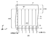
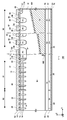
- FIG. 1 It is sectional drawing which shows an example of the semiconductor device 100.
- the oxygen chemical concentration C OX, impurity chemical concentration C I, hydrogen chemical concentration C H In the position shown in line A-A of FIG. 1, the oxygen chemical concentration C OX, impurity chemical concentration C I, hydrogen chemical concentration C H, and shows an example of the distribution of the depth direction of the VOH defect concentration N VOH.
- the oxygen chemical concentration C OX, impurity chemical concentration C I, hydrogen chemical concentration C H In the position shown in line A-A of FIG. 1, the oxygen chemical concentration C OX, impurity chemical concentration C I, hydrogen chemical concentration C H, and shows another example of the distribution of the depth direction of the VOH defect concentration N VOH
- one side in the direction parallel to the depth direction of the semiconductor substrate is referred to as "upper” and the other side is referred to as “lower”.
- the upper surface is referred to as the upper surface and the other surface is referred to as the lower surface.
- the “up” and “down” directions are not limited to the direction of gravity or the direction when the semiconductor device is mounted.
- Cartesian coordinate axes of the X-axis, the Y-axis, and the Z-axis only specify the relative positions of the components and do not limit the specific direction.
- the Z axis does not limit the height direction with respect to the ground.
- the + Z-axis direction and the ⁇ Z-axis direction are opposite to each other. When the positive and negative directions are not described and the Z-axis direction is described, it means the direction parallel to the + Z-axis and the -Z-axis.
- the X-axis and the Y-axis are orthogonal axes parallel to the upper surface and the lower surface of the semiconductor substrate. Further, the axis perpendicular to the upper surface and the lower surface of the semiconductor substrate is defined as the Z axis.
- the direction of the Z axis may be referred to as a depth direction.
- the direction parallel to the upper surface and the lower surface of the semiconductor substrate including the X-axis and the Y-axis may be referred to as a horizontal direction.
- the upper surface side of the semiconductor substrate in the present specification it refers to a region from the center to the upper surface in the depth direction of the semiconductor substrate.
- the lower surface side of the semiconductor substrate it refers to a region from the center to the lower surface in the depth direction of the semiconductor substrate.
- error When referred to as “same” or “equal” in the present specification, it may include a case where there is an error due to manufacturing variation or the like.
- the error is, for example, within 10%.
- the conductive type of the doping region doped with impurities is described as P type or N type.
- an impurity may mean, in particular, either an N-type donor or a P-type acceptor, and may be referred to as a dopant.
- doping means that a donor or acceptor is introduced into a semiconductor substrate to obtain a semiconductor exhibiting an N-type conductive type or a semiconductor exhibiting a P-type conductive type.
- the doping concentration means the concentration of a donor or the concentration of an acceptor in a thermal equilibrium state.
- the net doping concentration means the net concentration of the donor concentration as the concentration of positive ions and the acceptor concentration as the concentration of negative ions, including the polarity of the charge.
- the donor concentration N D, the acceptor concentration and N A, the net doping concentration of the net at any position is N D -N A.
- the donor has the function of supplying electrons to the semiconductor.
- the acceptor has a function of receiving electrons from a semiconductor.
- Donors and acceptors are not limited to the impurities themselves.
- a VOH defect in which pores (V), oxygen (O) and hydrogen (H) are bonded in a semiconductor functions as a donor that supplies electrons.
- the description of P + type or N + type means that the doping concentration is higher than that of P type or N type
- the description of P-type or N-type means that the doping concentration is higher than that of P-type or N-type. It means that the concentration is low.
- the doping concentration is higher than that of P ++ type or N + type.
- the chemical concentration refers to the atomic density of impurities measured regardless of the state of electrical activation.
- the chemical concentration (atomic density) can be measured by, for example, secondary ion mass spectrometry (SIMS).
- the net doping concentration described above can be measured by a voltage-capacity measurement method (CV method).
- the carrier concentration measured by the spread resistance measurement method (SR method) may be used as the net doping concentration.
- the carrier concentration measured by the CV method or the SR method may be a value in a thermal equilibrium state.
- the donor concentration is sufficiently higher than the acceptor concentration, so that the carrier concentration in the region may be used as the donor concentration.
- the carrier concentration in the region may be used as the acceptor concentration.
- the peak value may be used as the concentration of donor, acceptor or net doping in the region.
- the concentration of donor, acceptor or net doping is substantially uniform, the average value of the concentration of donor, acceptor or net doping in the region may be used as the concentration of donor, acceptor or net doping.
- the carrier concentration measured by the SR method may be lower than the concentration of the donor or acceptor.
- the carrier mobility of the semiconductor substrate may be lower than the value in the crystalline state. The decrease in carrier mobility occurs when carriers are scattered due to disorder of the crystal structure due to lattice defects or the like.
- the concentration of the donor or acceptor calculated from the carrier concentration measured by the CV method or the SR method may be lower than the chemical concentration of the element indicating the donor or acceptor.
- the donor concentration of phosphorus or arsenic as a donor in a silicon semiconductor, or the acceptor concentration of boron (boron) as an acceptor is about 99% of these chemical concentrations.
- the donor concentration of hydrogen as a donor in a silicon semiconductor is about 0.1% to 10% of the chemical concentration of hydrogen.
- FIG. 1 is a cross-sectional view showing an example of the semiconductor device 100.
- the semiconductor device 100 includes a semiconductor substrate 10.
- the semiconductor substrate 10 is a substrate made of a semiconductor material.
- the semiconductor substrate 10 is a silicon substrate.
- At least one of a transistor element such as an insulated gate bipolar transistor (IGBT) and a diode element such as a freewheeling diode (FWD) is formed on the semiconductor substrate 10.
- a transistor element such as an insulated gate bipolar transistor (IGBT) and a diode element such as a freewheeling diode (FWD) is formed on the semiconductor substrate 10.
- IGBT insulated gate bipolar transistor
- FWD freewheeling diode
- N-type bulk donors are distributed throughout.
- the bulk donor is a donor due to the dopant contained in the ingot substantially uniformly during the production of the ingot that is the source of the semiconductor substrate 10.
- the bulk donor in this example is an element other than hydrogen.
- Bulk donor dopants are, for example, Group V and Group VI elements, such as, but are not limited to, phosphorus, antimony, arsenic, selenium or sulfur.
- the bulk donor in this example is phosphorus.
- Bulk donors are also included in the P-type region.
- the semiconductor substrate 10 may be a wafer cut out from a semiconductor ingot, or may be a chip obtained by fragmenting the wafer.
- the semiconductor ingot may be manufactured by any one of the Czochralski method (CZ method), the magnetic field application type Czochralski method (MCZ method), and the float zone method (FZ method).
- the oxygen chemical concentration contained in the substrate produced by the MCZ method is, for example, 1 ⁇ 10 17 to 7 ⁇ 10 17 atoms / cm 3 .
- the oxygen chemical concentration contained in the substrate manufactured by the FZ method is, for example, 1 ⁇ 10 15 to 5 ⁇ 10 16 atoms / cm 3 .
- the bulk donor concentration may use the chemical concentration of the bulk donor distributed throughout the semiconductor substrate 10, and may be a value between 90% and 100% of the chemical concentration. In a semiconductor substrate doped with a Group V or Group VI dopant such as phosphorus, the bulk donor concentration may be 1 ⁇ 10 11 / cm 3 or more and 3 ⁇ 10 13 / cm 3 or less.
- the bulk donor concentration of the semiconductor substrate doped with the group V and group VI dopants is preferably 1 ⁇ 10 12 / cm 3 or more and 1 ⁇ 10 13 / cm 3 or less.
- a non-doped substrate that does not substantially contain a bulk dopant such as phosphorus may be used as the semiconductor substrate 10.
- the bulk donor concentration ( NB0 ) of the non-doping substrate is, for example, 1 ⁇ 10 10 / cm 3 or more and 5 ⁇ 10 12 / cm 3 or less.
- the bulk donor concentration ( NB0 ) of the non-doping substrate is preferably 1 ⁇ 10 11 / cm 3 or more.
- the bulk donor concentration ( NB0 ) of the non-doping substrate is preferably 5 ⁇ 10 12 / cm 3 or less.
- the semiconductor substrate 10 has an upper surface 21 and a lower surface 23.
- the upper surface 21 and the lower surface 23 are two main surfaces of the semiconductor substrate 10.
- the orthogonal axes in the plane parallel to the upper surface 21 and the lower surface 23 are the X-axis and the Y-axis
- the axes perpendicular to the upper surface 21 and the lower surface 23 are the Z-axis.
- a charged particle beam is injected into the semiconductor substrate 10 from the lower surface 23 at a predetermined depth position Z1.
- the main surface of the semiconductor substrate 10 into which the charged particle beam is injected is not limited to the lower surface 23, and may be the upper surface 21.
- the distance in the Z-axis direction from the upper surface 21 may be referred to as a depth position.
- the central position of the semiconductor substrate 10 in the depth direction is defined as the depth position Zc.
- the depth position Z1 is a position where the distance from the upper surface 21 in the Z-axis direction is Z1.
- the depth position Z1 is arranged on the upper surface 21 side (the region between the depth position Zc and the upper surface 21) of the semiconductor substrate 10.
- Injecting a charged particle beam into the depth position Z1 means that the average distance (also referred to as a range) for the charged particle to pass through the inside of the semiconductor substrate 10 is Z1.
- the charged particles are accelerated by the acceleration energy corresponding to the predetermined depth position Z1 and introduced into the semiconductor substrate 10.
- the region where the charged particles have passed through the inside of the semiconductor substrate 10 is defined as the passing region 106.
- the passage region 106 is from the lower surface 23 of the semiconductor substrate 10 to the depth position Z1.
- the charged particle is a particle capable of forming a lattice defect in the passing region 106.
- the charged particles are, for example, hydrogen ions, helium ions, or electrons.
- the charged particles may be injected into the entire surface of the semiconductor substrate 10 on the XY plane, or may be injected into only a part of the region.
- the semiconductor substrate 10 has a first peak 401 of charged particle concentration at the depth position Z1.
- the charged particle is hydrogen. That is, the semiconductor substrate 10 of this example has the first peak 401 in the depth direction of the hydrogen chemical concentration at the depth position Z1.
- the first peak 401 may be a peak in the helium chemical concentration distribution.
- lattice defects such as single-atomic pores (V) and double-atomic pores (VV), which are mainly pores, are present. It is formed. Atoms adjacent to the vacancies have dangling bonds. Lattice defects include interstitial atoms, dislocations, etc., and in a broad sense, donors and acceptors may also be included. Sometimes referred to simply as a lattice defect. Further, the crystallinity of the semiconductor substrate 10 may be strongly disturbed due to the formation of many lattice defects by injecting charged particles into the semiconductor substrate 10. In the present specification, this disorder of crystallinity may be referred to as disorder.
- oxygen is contained in the entire semiconductor substrate 10.
- the oxygen is intentionally or unintentionally introduced during the manufacture of semiconductor ingots.
- hydrogen is contained in at least a part of the passage region 106. The hydrogen may be intentionally injected into the semiconductor substrate 10.
- hydrogen ions are injected from the lower surface 23 into the depth position Z2.
- the hydrogen ion in this example is a proton.
- the main surface of the semiconductor substrate 10 into which hydrogen ions are injected is not limited to the lower surface 23, and may be the upper surface 21.
- the semiconductor substrate 10 of this example has a second peak 402 of hydrogen chemical concentration at the depth position Z2. In FIG. 1, the first peak 401 and the second peak 402 are schematically shown by broken lines.
- the depth position Z2 may be included in the passage area 106.
- the depth position Z2 of this example is arranged on the lower surface 23 side (the region between the depth position Zc and the lower surface 23) of the semiconductor substrate 10.
- the hydrogen injected into the depth position Z1 may be diffused into the passing region 106, and hydrogen may be introduced into the passing region 106 by another method. In these cases, hydrogen ions may not be injected into the depth position Z2.
- the passage region 106 is formed in the semiconductor substrate 10 and hydrogen ions are injected into the semiconductor substrate 10, hydrogen (H), pores (V) and oxygen (O) are bonded inside the semiconductor substrate 10.
- VOH defects are formed.
- heat-treating the semiconductor substrate 10 sometimes referred to as annealing in the present specification
- hydrogen is diffused and the formation of VOH defects is promoted.
- heat-treating after forming the passing region 106 hydrogen can be bonded to the vacancies, so that hydrogen can be suppressed from being released to the outside of the semiconductor substrate 10.
- the VOH defect functions as a donor that supplies electrons.
- VOH defects may be referred to simply as hydrogen donors.
- a hydrogen donor is formed in the passing region 106.
- the doping concentration of the hydrogen donor at each position is lower than the chemical concentration of hydrogen at each position.
- the ratio of the chemical concentration of hydrogen to the doping concentration of the hydrogen donor (VOH defect) with respect to the chemical concentration of hydrogen is a value of 0.1% to 30% (that is, 0.001 or more and 0.3 or less). good.
- the ratio of the chemical concentration of hydrogen to the doping concentration of the hydrogen donor (VOH defect) is 1% to 5%.
- VOH defects having a distribution similar to the chemical concentration distribution of hydrogen and VOH defects having a distribution similar to the distribution of pore defects in the passage region 106 are used as hydrogen donors or donors. Called hydrogen.
- the donor concentration in the passing region 106 of the semiconductor substrate 10 can be made higher than the doping concentration of the bulk donor (sometimes simply referred to as the bulk donor concentration).
- the semiconductor substrate 10 having a predetermined bulk donor concentration must be prepared according to the characteristics of the element to be formed on the semiconductor substrate 10, particularly the rated voltage or the withstand voltage.
- the donor concentration of the semiconductor substrate 10 can be adjusted by controlling the dose amount of the charged particles. Therefore, the semiconductor device 100 can be manufactured by using a semiconductor substrate having a bulk donor concentration that does not correspond to the characteristics of the device or the like.
- the dose amount of charged particles can be controlled with relatively high accuracy. Therefore, the concentration of lattice defects generated by injecting charged particles can be controlled with high accuracy, and the donor concentration in the passing region can be controlled with high accuracy.
- the depth position Z1 may be arranged in a range of half or less of the thickness of the semiconductor substrate 10 with reference to the upper surface 21, or may be arranged in a range of 1/4 or less of the thickness of the semiconductor substrate 10.
- the depth position Z2 may be arranged in a range of half or less of the thickness of the semiconductor substrate 10 with reference to the lower surface 23, or may be arranged in a range of 1/4 or less of the thickness of the semiconductor substrate 10.
- the depth position Z1 and the depth position Z2 are not limited to these ranges.
- the semiconductor substrate 10 has an oxygen reduction region 450 on the upper surface side.
- the upper surface side oxygen reduction region 450 is a region inside the semiconductor substrate 10 and is a region in contact with the upper surface 21 of the semiconductor substrate 10. Further, the upper surface side oxygen reduction region 450 is a region in which the oxygen chemical concentration decreases as the depth position approaches the upper surface 21.
- the oxygen reduction region 450 on the upper surface side may be a region in which the oxygen chemical concentration decreases over a length of 3% or more of the substrate thickness of the semiconductor substrate 10, and the oxygen chemical concentration extends over a length of 5% or more of the substrate thickness. It may be a region where the concentration decreases, and may be a region where the oxygen chemical concentration decreases over a length of 10% or more of the substrate thickness.
- the substrate thickness refers to the thickness of the semiconductor substrate 10 in the depth direction.
- the semiconductor ingot or the wafer cut out from the ingot contains almost uniform concentration of oxygen in the entire substrate.
- the variation in oxygen chemical concentration between substrates is relatively large.
- the concentration of VOH defects formed by injecting hydrogen tends to vary.
- the semiconductor substrate 10 is annealed at a predetermined annealing temperature and a predetermined annealing time.
- the semiconductor substrate 10 may be annealed in the state of a wafer cut out from the ingot, or may be annealed in the state of a chip cut out from the wafer.
- Annealing is preferably performed before injection of the charged particle beam.
- the annealing before injection of the charged particle beam may be referred to as oxygen annealing.
- the oxygen annealing time is such a long time that oxygen having a concentration of a solid solution limit corresponding to the oxygen annealing temperature is introduced into the substrate.
- the oxygen annealing time may be 1 hour or more, 2 hours or more, or 10 hours or more.
- the solid solution limit of oxygen refers to the limit concentration of oxygen that can be dissolved in the substrate, and changes depending on the oxygen annealing temperature.
- the oxygen annealing temperature is, for example, 1000 ° C. or higher, but is not limited thereto.
- the oxygen annealing temperature may be set so that the solid solution limit of oxygen is sufficiently higher than the oxygen chemical concentration of the semiconductor substrate 10 before oxygen annealing.
- oxygen annealing with an oxygen annealing time of a certain time or longer oxygen having a chemical concentration substantially matching the solid solution limit is introduced into the semiconductor substrate 10. Therefore, the oxygen chemical concentration of the semiconductor substrate 10 can be controlled by controlling the oxygen annealing temperature so that the solid solution limit is set according to the desired oxygen chemical concentration. Further, since the oxygen annealing temperature can be controlled relatively easily, the variation in oxygen chemical concentration between the substrates can be reduced.
- the upper surface side oxygen reduction region 450 is formed on the semiconductor substrate 10.
- An oxygen reduction region on the lower surface side is also formed in a region in contact with the lower surface 23 of the semiconductor substrate 10. However, when the lower surface 23 side of the semiconductor substrate 10 is ground, the oxygen reduction region on the lower surface side may not remain.
- the variation in oxygen chemical concentration in the semiconductor substrate 10 can be reduced. Therefore, it becomes easy to control the concentration of VOH defects, and it becomes easy to control the donor concentration of the semiconductor substrate 10.
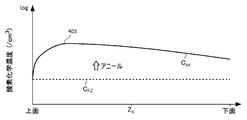
- FIG. 2 is, at the position shown in line A-A of FIG. 1, the depth of the oxygen chemical concentration C OX, impurity chemical concentration C I, hydrogen chemical concentration C H, VOH defect concentration N VOH, and net doping concentration N D An example of distribution in the vertical direction is shown.
- FIG. 2 shows each distribution after performing oxygen annealing and hydrogen annealing after hydrogen injection.
- the horizontal axis of FIG. 2 indicates the depth position from the upper surface 21, and the vertical axis indicates each concentration per unit volume on the logarithmic axis.
- the chemical concentration in FIG. 2 is measured by, for example, the SIMS method. 2 shows a bulk donor concentration N B with a broken line. Bulk donor concentration N B may be uniform throughout the semiconductor substrate 10.
- the semiconductor substrate 10 of this example is an MCZ substrate as an example.
- the distribution of oxygen chemical concentration COX has an upper surface oxygen reduction region 450.
- oxygen in the vicinity of the upper surface 21 is diffused outward.
- the lower surface 23 side of the semiconductor substrate 10 is ground after oxygen annealing. Therefore, the lower surface 23 of the semiconductor substrate 10 is not provided with an oxygen reduction region on the lower surface side.
- the reduction rate of the oxygen chemical concentration with respect to the unit distance in the depth direction may increase as it approaches the upper surface 21. That is, the closer to the upper surface 21, the steeper the oxygen chemical concentration may be.
- the distribution of oxygen chemical concentration COX has a maximum value region 452.
- the maximum value region 452 is a region in which the oxygen chemical concentration C OX is the maximum value C OX_max in the depth direction and the oxygen chemical concentration C OX is a predetermined boundary concentration C b or more.
- the boundary concentration C b may be 50%, 70%, 80% or more, 90% or more, or 100% of the maximum value COX_max.
- the upper surface side oxygen reduction region 450 of this example is arranged between the maximum value region 452 and the upper surface 21. Let Zb be the depth position of the boundary between the oxygen reduction region 450 on the upper surface side and the maximum value region 452. Further, the maximum value region 452 of this example is provided from the depth position Zb to the lower surface 23.
- the maximum value COX_max may be 3 ⁇ 10 15 atoms / cm 3 or more and 2 ⁇ 10 18 atoms / cm 3 or less.
- the maximum value COX_max may be 1 ⁇ 10 16 atoms / cm 3 or more, and may be 1 ⁇ 10 17 atoms / cm 3 or more.
- the maximum value COX_max may be 1 ⁇ 10 18 atoms / cm 3 or less, and may be 1 ⁇ 10 17 atoms / cm 3 or less.
- Impurity chemical concentration C I has a first peak 401 in the depth position Z1.
- the impurity is hydrogen.
- Distribution of the impurity chemical concentration C I includes an upper skirt 411 that impurity chemical concentration C I toward the upper surface 21 from the first peak 401 is reduced, the impurity chemical concentration C I toward the lower surface 23 from the first peak 401 is reduced It has a lower hem 421 and.
- impurities hydrogen in this example
- the upper hem 411 is steeply impurity chemical concentration C I than the lower skirt 421 may be reduced.
- the lower hem 421 may be provided from the first peak 401 to the lower surface 23.
- Impurity chemical concentration C I can be a chemical concentration of implanted hydrogen from the bottom surface 23 to the depth position Z1 of the semiconductor substrate 10.
- the first peak 401 may be arranged in the upper surface side oxygen reduction region 450.
- the depth position Z1 of the first peak 401 may be arranged on the upper surface 21 side of the depth position Zc.
- the depth position Z1 of the first peak 401 may be arranged on the upper surface 21 side of the depth position Z b.
- Hydrogen chemical concentration C H of the present example the first peak 401, disposed at a depth position Z2 between the lower surface 23, a second peak 402.
- the second peak 402 of this example is arranged in the maximum value region 452.
- the value of the chemical concentration of the second peak 402 may be larger than the value of the chemical concentration of the first peak 401. This facilitates the diffusion of hydrogen into the passage region 106.
- the value of the second peak 402 may be twice or more, five times or more, ten times or more, or 100 times or more the value of the first peak 401.
- Distribution of the hydrogen chemical concentration C H is an upper skirt 412 that hydrogen chemical concentration C H toward the upper surface 21 of the second peak 402 is reduced, the hydrogen chemical concentration C H toward the lower surface 23 of the second peak 402 is reduced It has a lower hem 422 and. As described in FIG. 1, hydrogen ions are injected from the lower surface 23 into the depth position Z2. Therefore, the upper hem 412, steeply hydrogen chemical concentration C H than the lower skirt 422 may be reduced. However, since hydrogen is diffused from the second peak 402 to the first peak 401 by heat-treating the semiconductor substrate 10, the upper hem 412 may have a gentler portion than the lower hem 422. Each position between the first peak 401 and a second peak 402, may be present hydrogen with 10 times more chemical concentration of bulk donor concentration N B may be present hydrogen more than 100 times, 200 times or more hydrogen may be present.
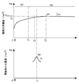
- the distribution of the VOH defect concentration N VOH of this example has a third peak 403 at the depth position Z1. At the depth position Z1, many pore defects are formed due to the injection of charged particle beams. Therefore, many VOH defects are likely to be formed at the depth position Z1. Further, the distribution of the VOH defect concentration N VOH of this example has a fourth peak 404 at the depth position Z2. At the depth position Z2, many vacancy defects due to hydrogen ion implantation are formed. Therefore, many VOH defects are likely to be formed at the depth position Z2.
- Distribution of VOH defect concentration N VOH includes an upper skirt 413 VOH defect concentration N VOH decreases toward the third peak 403 on the upper surface 21, VOH defect concentration N VOH decreases toward the lower surface 23 from the third peak 403 It has a lower hem 423 and.
- the upper hem 413 may have a steeper VOH defect concentration N VOH than the lower hem 423.
- Distribution of VOH defect concentration N VOH includes an upper skirt 414 VOH defect concentration N VOH decreases toward the upper surface 21 from the fourth peak 404, VOH defect concentration N VOH decreases toward the lower surface 23 from the fourth peak 404 It has a lower hem 424 and.
- the upper hem 414 may have a steeper VOH defect concentration N VOH than the lower hem 424.
- the net doping concentration N D of this example has a concentration obtained by adding the bulk donor concentration N B and the VOH defect concentration N VOH.
- Bulk donor concentration N B since almost constant in the entire semiconductor substrate 10, the shape of the distribution of net doping concentration N D is similar to the shape of the distribution of VOH defect concentration N VOH.
- Distribution of net doping concentration N D of the present embodiment includes a fifth peak 425 in the depth position Z1. Further, the distribution of the net doping concentration N D of this example has a sixth peak 426 in the depth position Z2. Distribution of net doping concentration N D includes an upper skirt 435 that the net doping concentration N D toward the top surface 21 from the fifth peak 425 is reduced, the net doping concentration toward the lower surface 23 from the fifth peak 425 N D Has a lower hem 445 and a reduced hem. The upper hem 435 may have a steeper net doping concentration N D than the lower hem 445.
- Distribution of net doping concentration N D includes an upper skirt 436 that the net doping concentration N D decreases toward the upper surface 21 from the sixth peak 426, net doping concentration toward the lower surface 23 from the sixth peak 426 N D Has a lower hem 446 and is reduced.
- the upper hem 436 may have a steeper net doping concentration N D than the lower hem 446.
- the positions of the vertices of the first peak 401, the third peak 403, and the fifth peak 425 do not have to be exactly the same.
- the positions of the vertices of the second peak 402, the fourth peak 404, and the sixth peak 426 do not have to be exactly the same. If the vertices of the other peak are arranged within the full width at half maximum of one peak, the two peaks may be provided at the same position.
- the passage region 106 because VOH defects are formed, the donor concentration in the pass region 106 is higher than the bulk donor concentration N B.
- the donor concentration is a region higher than the bulk donor concentration N B, referred to as a high-concentration region 460.
- the high-concentration region 460 includes the depth position Zc of the semiconductor substrate 10 and is provided over a predetermined length in the depth direction.
- the length of the high concentration region 460 in the depth direction may be 50% or more, 60% or more, 70% or more, 80% or more, 90% or more of the substrate thickness. It may be the above.
- the high concentration region 460 of this example is provided from the first peak 401 to the lower surface 23.
- a high concentration region 460 may be provided above the first peak 401.
- the first peak 401 has a predetermined full width at half maximum in the depth direction. Therefore, a pore defect is formed above the first peak 401, and a high concentration region 460 is formed. However, the high concentration region 460 above the first peak 401 has a smaller width in the depth direction than the high concentration region 460 below the first peak 401.
- VOH defect concentration N VOH may be a higher region than bulk donor concentration N B.
- the VOH defect concentration N VOH can be controlled with high precision, it is possible to suppress the variation in donor concentration.
- VOH defect concentration N VOH may be more than twice the bulk donor concentration N B, may be more than five times, and may be 10 times or more.
- the first peak 401 is arranged at the end of the high concentration region 460 on the upper surface 21 side.
- the first peak 401 may be arranged in the maximum value region 452 or on the upper surface 21 side of the maximum value region 452.
- the first peak 401 of this example is arranged in the oxygen reduction region 450 on the upper surface side.
- the first peak 401 the oxygen chemical concentration C OX is, may be placed in more than 10% of the area of maximum value C OX_max may be arranged in more than 30% of the area may be arranged in more than 50% of the area , 70% or more of the region may be arranged, and 90% or more of the region may be arranged.
- the oxygen chemical concentration C OX is small, the fluctuation of the oxygen chemical concentration C OX becomes large with respect to the displacement in the depth direction.
- FIG. 3 shows each distribution after the heat treatment.
- the oxygen chemical concentration COX is different from the example of FIG.
- Other concentration distributions are the same as in the example of FIG.
- the semiconductor substrate 10 of this example is, for example, an FZ substrate.
- Oxygen chemical concentration C OX of this embodiment a depth position Z p, having an oxygen concentration peak 405 showing the maximum value C OX_max.
- Range of the maximum value C OX_max may be similar to the range of the maximum value C OX_max in FIG.
- the distribution of the oxygen chemical concentration COX of this example has a lower surface side oxygen reduction region 454 in addition to the maximum value region 452 and the upper surface side oxygen reduction region 450 shown in FIG.
- the lower surface side oxygen reduction region 454 is a region that is in contact with the lower surface 23 and the oxygen chemical concentration COX decreases as it approaches the lower surface 23.
- the maximum value region 452 is arranged between the upper surface side oxygen reduction region 450 and the lower surface side oxygen reduction region 454.
- the lower surface side oxygen reduction region 454 may be a region in which the oxygen chemical concentration COX gradually decreases as compared with the upper surface side oxygen reduction region 450.
- the lower surface side oxygen reduction region 454 may be longer than the upper surface side oxygen reduction region 450 in the depth direction. As a result, the fluctuation of the oxygen chemical concentration COX in the semiconductor substrate 10 can be made relatively small as compared with the case where the upper surface side oxygen reduction region 450 is long.
- the length of the lower surface side oxygen reduction region 454 in the depth direction may be 30% or more, 40% or more, or 50% or more of the substrate thickness.
- the second peak 402 and the fourth peak 404 of this example are arranged in the lower surface side oxygen reduction region 454.
- the first peak 401 may be arranged in the upper surface side oxygen reduction region 450.
- the depth position Z1 of the first peak 401 may be arranged on the upper surface 21 side of the depth position Zc.
- Depth position Z1 of the first peak 401 may be disposed on the top surface 21 side of the depth position Z p.
- the depth position Z1 of the first peak 401 may be arranged on the upper surface 21 side of the depth position Z b.
- the depth position Z1 of the first peak 401 may be arranged between the depth position Z p and the depth position Z b.
- FIG. 4 is a diagram showing an example of changes in the oxygen chemical concentration distribution of the MCZ substrate before and after oxygen annealing.
- the MCZ substrate Before oxygen annealing, the MCZ substrate has a relatively high oxygen chemical concentration C MCZ.
- the oxygen chemical concentration C MCZ is higher than, for example, the solid solution limit of the oxygen annealing temperature.
- oxygen in the substrate diffuses outward, and the oxygen chemical concentration COX in the substrate becomes substantially equal to the solid solution limit.
- the oxygen chemical concentration COX becomes smaller as it approaches the upper surface 21.
- the lower surface 23 side is ground after oxygen annealing. Therefore, on the lower surface 23 side, the oxygen chemical concentration COX is substantially constant.
- FIG. 5 is a diagram showing an example of changes in the oxygen chemical concentration distribution of the FZ substrate before and after oxygen annealing.
- the FZ substrate Before oxygen annealing, the FZ substrate has a relatively low oxygen chemical concentration C FZ.
- the oxygen chemical concentration C FZ is lower than, for example, the solid solution limit of the oxygen annealing temperature.
- oxygen is introduced into the substrate, and the oxygen chemical concentration COX in the substrate becomes substantially equal to the solid solution limit in a region where the distance from the upper surface 21 of the semiconductor substrate 10 is small. Since oxygen is difficult to be introduced in the region where the distance from the upper surface 21 is large, the oxygen chemical concentration COX gradually decreases as the distance from the upper surface 21 increases.
- the oxygen chemical concentration COX becomes smaller as it approaches the upper surface 21. Therefore, the oxygen chemical concentration COX may have an oxygen concentration peak 405.
- the lower surface 23 side is ground after oxygen annealing. Therefore, on the lower surface 23 side, the oxygen chemical concentration COX does not have a peak and gradually and monotonically decreases toward the lower surface 23.
- the oxygen chemical concentration inside the semiconductor substrate 10 can be controlled by the oxygen annealing temperature or the like. Therefore, the variation in VOH defect concentration can be reduced.
- FIG. 6 is a diagram showing a distribution example of the recombination center concentration Nr and the oxygen chemical concentration COX.
- the oxygen chemical concentration COX is similar to the example shown in FIG. 2 or FIG.
- FIG. 6 in the distribution of the oxygen chemical concentration COX shown in FIG. 3, the vicinity of the upper surface 21 is enlarged and shown.
- a recombination center such as a vacancy defect may be formed for the purpose of adjusting the lifetime of the carrier.
- a recombination center can be formed by injecting charged particles such as hydrogen, helium, or an electron beam into the semiconductor substrate 10.
- the recombination center concentration N r has a recombination center peak 406 in the depth position Z r.
- a calculation method using a well-known calculation software or tool is known for the pore density (see, for example, http://www.srim.org/).
- the position of the minimum value of the specific resistance distribution in the depth direction of the semiconductor substrate 10 may be the position of the recombination center peak 406.
- the recombination center peak 406 may be formed on the upper surface 21 side of the semiconductor substrate 10 in a region where the oxygen chemical concentration COX is 70% or more.
- the recombination center peak 406 can combine with hydrogen to form a VOH defect. Therefore, if the oxygen chemical concentration COX varies widely, the concentration at the recombination center tends to vary, and it becomes difficult to accurately adjust the carrier lifetime.
- the recombination center peak 406 is arranged in a region where the oxygen chemical concentration COX concentration is relatively stable, so that the recombination center concentration can be easily controlled and the carrier lifetime can be accurately controlled. Can be adjusted.
- the oxygen chemical concentration C OX is well formed in the region of 80% or more of the maximum value C OX_max, it may be arranged in more than 90% of the area.
- Depth position Z r may be the same position and depth position Z1 of the charged particle beam is injected. That is, the carrier lifetime may be adjusted by injecting a charged particle beam into the depth position Z1. Further, the depth position Zr may be a position near the depth position Z1 and closer to the injection surface (lower surface 23 in this example) of the charged particle beam than the depth position Z1.
- the charged particle injected into the depth position Z1 is a hydrogen ion
- the recombination center in the vicinity of the depth position Z1 becomes a VOH defect by binding with hydrogen. Therefore, recombination center concentration at the depth position Z1 is lowered, the depth position Z r is implanted surface of the hydrogen ions (in this example the lower surface 23) is shifted to the side.
- Distance depth position Z1 and depth position Z r may be at 5 ⁇ m or less, may be at 3 ⁇ m or less, may be 1 ⁇ m or less.
- the depth position Z r may be a position different from the depth position Z1.
- FIG. 7 is a diagram illustrating the position of the third peak 403.
- examples of deformation of the position of the third peak 403 are shown as the third peaks 403-1, 4032, and 403-3.
- the semiconductor substrate 10 is provided with any third peak 403.
- the third peak 403-1 is arranged between the oxygen concentration peak 405 and the boundary position Zb.
- Boundary position Zb is the maximum value region 452 of the oxygen chemical concentration C OX, a boundary position between the upper surface oxygen reduction region 450.
- the high concentration region 460 see FIGS. 2 and 3 can be formed long, and the variation in the value of the third peak 403 can be suppressed.
- the third peak 403-2 is arranged in the upper surface side oxygen reduction region 450.
- the high concentration region 460 can be formed longer.
- the third peak 403-3 according to another example is arranged between the oxygen concentration peak 405 and the depth position Zc. In this case, the third peak 403-3, variations in oxygen chemical concentration C OX may be disposed gentle region relatively.
- the third peak 403-3 may be arranged in the maximum value region 452.
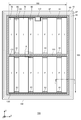
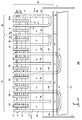
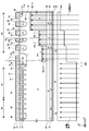
- FIG. 8 is an example of a top view of the semiconductor device 100.
- FIG. 8 shows the positions where each member is projected onto the upper surface of the semiconductor substrate 10. In FIG. 8, only a part of the members of the semiconductor device 100 is shown, and some members are omitted.
- the semiconductor device 100 includes the semiconductor substrate 10 described with reference to FIGS. 1 to 7.
- the semiconductor substrate 10 has an end side 102 when viewed from above. When simply referred to as a top view in the present specification, it means that the semiconductor substrate 10 is viewed from the top surface side.
- the semiconductor substrate 10 of this example has two sets of end sides 102 facing each other in a top view. In FIG. 1, the X-axis and the Y-axis are parallel to either end 102. The Z-axis is perpendicular to the upper surface of the semiconductor substrate 10.
- the semiconductor substrate 10 is provided with an active portion 160.
- the active portion 160 is a region in which a main current flows in the depth direction between the upper surface and the lower surface of the semiconductor substrate 10 when the semiconductor device 100 operates.
- An emitter electrode is provided above the active portion 160, but is omitted in FIG.
- the active unit 160 is provided with at least one of a transistor unit 70 including a transistor element such as an IGBT and a diode unit 80 including a diode element such as a freewheeling diode (FWD).
- a transistor unit 70 including a transistor element such as an IGBT and a diode unit 80 including a diode element such as a freewheeling diode (FWD).
- the transistor portion 70 and the diode portion 80 are alternately arranged along a predetermined arrangement direction (X-axis direction in this example) on the upper surface of the semiconductor substrate 10.
- the active portion 160 may be provided with only one of the transistor portion 70 and the diode portion 80.
- the symbol “I” is attached to the region where the transistor portion 70 is arranged, and the symbol “F” is attached to the region where the diode portion 80 is arranged.
- the direction perpendicular to the arrangement direction in the top view may be referred to as a stretching direction (Y-axis direction in FIG. 8).
- the transistor portion 70 and the diode portion 80 may each have a longitudinal length in the stretching direction. That is, the length of the transistor portion 70 in the Y-axis direction is larger than the width in the X-axis direction. Similarly, the length of the diode portion 80 in the Y-axis direction is larger than the width in the X-axis direction.
- the stretching direction of the transistor portion 70 and the diode portion 80 may be the same as the longitudinal direction of each trench portion described later.
- the diode portion 80 has an N + type cathode region in a region in contact with the lower surface of the semiconductor substrate 10.
- the region provided with the cathode region is referred to as a diode portion 80. That is, the diode portion 80 is a region that overlaps with the cathode region in the top view.
- a P + type collector region may be provided on the lower surface of the semiconductor substrate 10 in a region other than the cathode region.
- the diode portion 80 may also include an extension region 81 in which the diode portion 80 is extended in the Y-axis direction to the gate wiring described later.
- a collector area is provided on the lower surface of the extension area 81.
- the transistor portion 70 has a P + type collector region in a region in contact with the lower surface of the semiconductor substrate 10. Further, in the transistor portion 70, a gate structure having an N-type emitter region, a P-type base region, a gate conductive portion and a gate insulating film is periodically arranged on the upper surface side of the semiconductor substrate 10.
- the semiconductor device 100 may have one or more pads above the semiconductor substrate 10.
- the semiconductor device 100 of this example has a gate pad 112.
- the semiconductor device 100 may have pads such as an anode pad, a cathode pad, and a current detection pad.
- Each pad is arranged in the vicinity of the end side 102.
- the vicinity of the end side 102 refers to a region between the end side 102 and the emitter electrode in top view.
- each pad may be connected to an external circuit via wiring such as a wire.
- a gate potential is applied to the gate pad 112.
- the gate pad 112 is electrically connected to the conductive portion of the gate trench portion of the active portion 160.
- the semiconductor device 100 includes a gate wiring that connects the gate pad 112 and the gate trench portion. In FIG. 8, the gate wiring is hatched with diagonal lines.
- the gate wiring of this example has an outer peripheral gate wiring 130 and an active side gate wiring 131.
- the outer peripheral gate wiring 130 is arranged between the active portion 160 and the end side 102 of the semiconductor substrate 10 in a top view.
- the outer peripheral gate wiring 130 of this example surrounds the active portion 160 in a top view.
- the region surrounded by the outer peripheral gate wiring 130 in the top view may be the active portion 160.
- the outer peripheral gate wiring 130 is connected to the gate pad 112.
- the outer peripheral gate wiring 130 is arranged above the semiconductor substrate 10.
- the outer peripheral gate wiring 130 may be a metal wiring containing aluminum or the like.
- the active side gate wiring 131 is provided in the active portion 160. By providing the active side gate wiring 131 in the active portion 160, it is possible to reduce variations in the wiring length from the gate pad 112 in each region of the semiconductor substrate 10.
- the active side gate wiring 131 is connected to the gate trench portion of the active portion 160.
- the active side gate wiring 131 is arranged above the semiconductor substrate 10.
- the active side gate wiring 131 may be wiring formed of a semiconductor such as polysilicon doped with impurities.
- the active side gate wiring 131 may be connected to the outer peripheral gate wiring 130.
- the active side gate wiring 131 of this example is provided so as to extend in the X-axis direction from one outer peripheral gate wiring 130 to the other outer peripheral gate wiring 130 at substantially the center in the Y-axis direction so as to cross the active portion 160. There is.
- the transistor portion 70 and the diode portion 80 may be alternately arranged in the X-axis direction in each divided region.
- the semiconductor device 100 includes a temperature sense unit (not shown) which is a PN junction diode made of polysilicon or the like, and a current detection unit (not shown) which simulates the operation of a transistor unit provided in the active unit 160. May be good.
- a temperature sense unit (not shown) which is a PN junction diode made of polysilicon or the like
- a current detection unit (not shown) which simulates the operation of a transistor unit provided in the active unit 160. May be good.
- the semiconductor device 100 of this example includes an edge termination structure portion 90 between the active portion 160 and the end side 102.
- the edge terminal structure portion 90 of this example is arranged between the outer peripheral gate wiring 130 and the end side 102.
- the edge termination structure 90 relaxes the electric field concentration on the upper surface side of the semiconductor substrate 10.
- the edge termination structure 90 has a plurality of guard rings 92.
- the guard ring 92 is a P-shaped region in contact with the upper surface of the semiconductor substrate 10.
- the guard ring 92 may surround the active portion 160 in top view.
- the plurality of guard rings 92 are arranged at predetermined intervals between the outer peripheral gate wiring 130 and the end side 102.
- the guard ring 92 arranged on the outside may surround the guard ring 92 arranged on the inside.
- the outside refers to the side close to the end side 102, and the inside refers to the side close to the outer peripheral gate wiring 130.
- the edge termination structure 90 may further include at least one of a field plate and a resurf provided in an annular shape surrounding the active portion 160.
- FIG. 9 is an enlarged view of the area A in FIG.
- the region A is a region including the transistor portion 70, the diode portion 80, and the active side gate wiring 131.
- the semiconductor device 100 of this example includes a gate trench portion 40, a dummy trench portion 30, a well region 11, an emitter region 12, a base region 14, and a contact region 15 provided inside the upper surface side of the semiconductor substrate 10.
- the gate trench portion 40 and the dummy trench portion 30 are examples of trench portions, respectively.
- the semiconductor device 100 of this example includes an emitter electrode 52 and an active side gate wiring 131 provided above the upper surface of the semiconductor substrate 10.
- the emitter electrode 52 and the active side gate wiring 131 are provided separately from each other.
- An interlayer insulating film is provided between the emitter electrode 52 and the active side gate wiring 131 and the upper surface of the semiconductor substrate 10, but this is omitted in FIG.
- a contact hole 54 is provided so as to penetrate the interlayer insulating film.
- each contact hole 54 is hatched with diagonal lines.
- the emitter electrode 52 is provided above the gate trench portion 40, the dummy trench portion 30, the well region 11, the emitter region 12, the base region 14, and the contact region 15.
- the emitter electrode 52 passes through the contact hole 54 and comes into contact with the emitter region 12, the contact region 15, and the base region 14 on the upper surface of the semiconductor substrate 10. Further, the emitter electrode 52 is connected to the dummy conductive portion in the dummy trench portion 30 through a contact hole provided in the interlayer insulating film.
- the emitter electrode 52 may be connected to the dummy conductive portion of the dummy trench portion 30 at the tip of the dummy trench portion 30 in the Y-axis direction.
- the active side gate wiring 131 is connected to the gate trench portion 40 through a contact hole provided in the interlayer insulating film.
- the active side gate wiring 131 may be connected to the gate conductive portion of the gate trench portion 40 at the tip portion 41 of the gate trench portion 40 in the Y-axis direction.
- the active side gate wiring 131 is not connected to the dummy conductive portion in the dummy trench portion 30.
- the emitter electrode 52 is made of a material containing metal. In FIG. 9, the range in which the emitter electrode 52 is provided is shown. For example, at least a part of the emitter electrode 52 is formed of an aluminum or aluminum-silicon alloy, for example, a metal alloy such as AlSi or AlSiCu.
- the emitter electrode 52 may have a barrier metal formed of titanium, a titanium compound, or the like in the lower layer of the region formed of aluminum or the like. Further, the contact hole may have a plug formed by embedding tungsten or the like so as to be in contact with the barrier metal and aluminum or the like.
- the well region 11 is provided so as to overlap the active side gate wiring 131.
- the well region 11 is extended to a predetermined width so as not to overlap with the active side gate wiring 131.
- the well region 11 of this example is provided away from the end of the contact hole 54 in the Y-axis direction on the active side gate wiring 131 side.
- the well region 11 is a second conductive type region having a higher doping concentration than the base region 14.
- the base region 14 of this example is P-type, and the well region 11 is P + type.
- Each of the transistor portion 70 and the diode portion 80 has a plurality of trench portions arranged in the arrangement direction.
- the transistor portion 70 of this example one or more gate trench portions 40 and one or more dummy trench portions 30 are alternately provided along the arrangement direction.
- the diode portion 80 of this example is provided with a plurality of dummy trench portions 30 along the arrangement direction.
- the diode portion 80 of this example is not provided with the gate trench portion 40.
- the gate trench portion 40 of this example connects two straight portions 39 (portions that are linear along the stretching direction) and two straight portions 39 that extend along the stretching direction perpendicular to the arrangement direction. It may have a tip 41.
- the stretching direction in FIG. 9 is the Y-axis direction.
- the tip portion 41 is provided in a curved shape in a top view.
- the dummy trench portion 30 is provided between the straight portions 39 of the gate trench portion 40.
- One dummy trench portion 30 may be provided between the straight portions 39, and a plurality of dummy trench portions 30 may be provided.
- the dummy trench portion 30 may have a linear shape extending in the stretching direction, and may have a straight portion 29 and a tip portion 31 as in the gate trench portion 40.
- the semiconductor device 100 shown in FIG. 9 includes both a linear dummy trench portion 30 having no tip portion 31 and a dummy trench portion 30 having a tip portion 31.
- the diffusion depth of the well region 11 may be deeper than the depth of the gate trench portion 40 and the dummy trench portion 30.
- the ends of the gate trench portion 40 and the dummy trench portion 30 in the Y-axis direction are provided in the well region 11 in the top view. That is, at the end of each trench in the Y-axis direction, the bottom of each trench in the depth direction is covered with the well region 11. Thereby, the electric field concentration at the bottom of each trench can be relaxed.
- a mesa part is provided between each trench part in the arrangement direction.
- the mesa portion refers to a region sandwiched between trench portions inside the semiconductor substrate 10.
- the upper end of the mesa portion is the upper surface of the semiconductor substrate 10.
- the depth position of the lower end of the mesa portion is the same as the depth position of the lower end of the trench portion.
- the mesa portion of this example is provided on the upper surface of the semiconductor substrate 10 by extending in the stretching direction (Y-axis direction) along the trench.
- the transistor portion 70 is provided with a mesa portion 60
- the diode portion 80 is provided with a mesa portion 61.
- a mesa portion when simply referred to as a mesa portion in the present specification, it refers to each of the mesa portion 60 and the mesa portion 61.
- a base region 14 is provided in each mesa section. Of the base region 14 exposed on the upper surface of the semiconductor substrate 10 in the mesa portion, the region closest to the active side gate wiring 131 is referred to as the base region 14-e. In FIG. 9, the base region 14-e arranged at one end in the extending direction of each mesa portion is shown, but the base region 14-e is also arranged at the other end of each mesa portion. Has been done.
- Each mesa portion may be provided with at least one of a first conductive type emitter region 12 and a second conductive type contact region 15 in a region sandwiched between base regions 14-e in a top view.
- the emitter region 12 of this example is N + type
- the contact region 15 is P + type.
- the emitter region 12 and the contact region 15 may be provided between the base region 14 and the upper surface of the semiconductor substrate 10 in the depth direction.
- the mesa portion 60 of the transistor portion 70 has an emitter region 12 exposed on the upper surface of the semiconductor substrate 10.
- the emitter region 12 is provided in contact with the gate trench portion 40.
- the mesa portion 60 in contact with the gate trench portion 40 may be provided with an exposed contact region 15 on the upper surface of the semiconductor substrate 10.
- Each of the contact region 15 and the emitter region 12 in the mesa portion 60 is provided from one trench portion in the X-axis direction to the other trench portion.
- the contact region 15 and the emitter region 12 of the mesa portion 60 are alternately arranged along the extending direction (Y-axis direction) of the trench portion.
- the contact region 15 and the emitter region 12 of the mesa portion 60 may be provided in a stripe shape along the extending direction (Y-axis direction) of the trench portion.
- an emitter region 12 is provided in a region in contact with the trench portion, and a contact region 15 is provided in a region sandwiched between the emitter regions 12.
- the emitter region 12 is not provided in the mesa portion 61 of the diode portion 80.
- a base region 14 and a contact region 15 may be provided on the upper surface of the mesa portion 61.
- a contact region 15 may be provided in contact with the respective base regions 14-e in the region sandwiched between the base regions 14-e on the upper surface of the mesa portion 61.
- a base region 14 may be provided in a region sandwiched between the contact regions 15 on the upper surface of the mesa portion 61.
- the base region 14 may be arranged over the entire region sandwiched between the contact regions 15.
- a contact hole 54 is provided above each mesa portion.
- the contact hole 54 is arranged in a region sandwiched between the base regions 14-e.
- the contact hole 54 of this example is provided above each region of the contact region 15, the base region 14, and the emitter region 12.
- the contact hole 54 is not provided in the region corresponding to the base region 14-e and the well region 11.
- the contact hole 54 may be arranged at the center of the mesa portion 60 in the arrangement direction (X-axis direction).
- an N + type cathode region 82 is provided in a region adjacent to the lower surface of the semiconductor substrate 10.
- a P + type collector region 22 may be provided on the lower surface of the semiconductor substrate 10 in a region where the cathode region 82 is not provided.
- FIG. 9 the boundary between the cathode region 82 and the collector region 22 is shown by a dotted line.
- the cathode region 82 is arranged away from the well region 11 in the Y-axis direction.
- the pressure resistance can be improved by securing the distance between the P-shaped region (well region 11) formed to a deep position and having a relatively high doping concentration and the cathode region 82.
- the end of the cathode region 82 of this example in the Y-axis direction is located farther from the well region 11 than the end of the contact hole 54 in the Y-axis direction.
- the end of the cathode region 82 in the Y-axis direction may be located between the well region 11 and the contact hole 54.
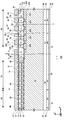
- FIG. 10 is a diagram showing an example of a bb cross section in FIG.
- the bb cross section is an XZ plane passing through the emitter region 12 and the cathode region 82.
- the semiconductor device 100 of this example has a semiconductor substrate 10, an interlayer insulating film 38, an emitter electrode 52, and a collector electrode 24 in the cross section.
- the interlayer insulating film 38 is provided on the upper surface of the semiconductor substrate 10.
- the interlayer insulating film 38 is a film containing at least one layer of an insulating film such as silicate glass to which impurities such as boron and phosphorus are added, a thermal oxide film, and other insulating films.
- the interlayer insulating film 38 is provided with the contact hole 54 described in FIG.
- the emitter electrode 52 is provided above the interlayer insulating film 38.
- the emitter electrode 52 is in contact with the upper surface 21 of the semiconductor substrate 10 through the contact hole 54 of the interlayer insulating film 38.
- the collector electrode 24 is provided on the lower surface 23 of the semiconductor substrate 10.
- the emitter electrode 52 and the collector electrode 24 are made of a metal material such as aluminum.
- the direction (Z-axis direction) connecting the emitter electrode 52 and the collector electrode 24 is referred to as a depth direction.
- the semiconductor substrate 10 has an N-type bulk doping region 18.
- the bulk doping region 18 is a region where the doping concentration of the bulk doping region 18 matches the donor concentration of the bulk donor.
- the bulk doping region 18 is provided in each of the transistor portion 70 and the diode portion 80.
- the mesa portion 60 of the transistor portion 70 is provided with an N + type emitter region 12 and a P-type base region 14 in order from the upper surface 21 side of the semiconductor substrate 10.
- a bulk doping region 18 is provided below the base region 14.
- the mesa portion 60 may be provided with an N + type storage region 16.
- the storage region 16 is located between the base region 14 and the bulk doping region 18.
- the emitter region 12 is exposed on the upper surface 21 of the semiconductor substrate 10 and is provided in contact with the gate trench portion 40.
- the emitter region 12 may be in contact with the trench portions on both sides of the mesa portion 60.
- the emitter region 12 has a higher doping concentration than the bulk doping region 18.
- the base region 14 is provided below the emitter region 12.
- the base region 14 of this example is provided in contact with the emitter region 12.
- the base region 14 may be in contact with the trench portions on both sides of the mesa portion 60.
- the storage area 16 is provided below the base area 14.
- the accumulation region 16 is an N + type region having a higher doping concentration than the bulk doping region 18.
- IE effect carrier injection promoting effect
- the storage region 16 may be provided so as to cover the entire lower surface of the base region 14 in each mesa portion 60.
- the mesa portion 61 of the diode portion 80 is provided with a P-type base region 14 in contact with the upper surface 21 of the semiconductor substrate 10. Below the base region 14, a bulk doping region 18 is provided. In the mesa portion 61, the accumulation region 16 may be provided below the base region 14.
- an N + type buffer region 20 may be provided on the lower surface 23 side of the bulk doping region 18 and the high concentration region 460.
- the doping concentration in the buffer region 20 is higher than the doping concentration in the bulk doping region 18.
- the buffer region 20 has one or more donor concentration peaks with higher donor concentrations than the bulk doping region 18. The plurality of donor concentration peaks are arranged at different positions in the depth direction of the semiconductor substrate 10.
- the donor concentration peak in the buffer region 20 may be, for example, a hydrogen (proton) or phosphorus concentration peak.
- the buffer region 20 may include a second peak 402 of hydrogen chemical concentration (see FIG. 2, etc.).
- the buffer region 20 may function as a field stop layer that prevents the depletion layer extending from the lower end of the base region 14 from reaching the P + type collector region 22 and the N + type cathode region 82.
- a P + type collector region 22 is provided below the buffer region 20.
- the acceptor concentration in the collector region 22 is higher than the acceptor concentration in the base region 14.
- the collector region 22 may include the same acceptors as the base region 14, or may include different acceptors.
- the acceptor of the collector region 22 is, for example, boron.
- an N + type cathode region 82 is provided below the buffer region 20.
- the donor concentration in the cathode region 82 is higher than the donor concentration in the bulk doping region 18.
- the donor of the cathode region 82 is, for example, hydrogen or phosphorus.
- the elements that serve as donors and acceptors in each region are not limited to the above-mentioned examples.
- the collector region 22 and the cathode region 82 are exposed on the lower surface 23 of the semiconductor substrate 10 and are connected to the collector electrode 24.
- the collector electrode 24 may come into contact with the entire lower surface 23 of the semiconductor substrate 10.
- the emitter electrode 52 and the collector electrode 24 are made of a metal material such as aluminum.
- One or more gate trench portions 40 and one or more dummy trench portions 30 are provided on the upper surface 21 side of the semiconductor substrate 10. Each trench portion penetrates the base region 14 from the upper surface 21 of the semiconductor substrate 10 and reaches the bulk doping region 18. In the region where at least one of the emitter region 12, the contact region 15 and the storage region 16 is provided, each trench portion also penetrates these doping regions and reaches the bulk doping region 18. The penetration of the trench portion through the doping region is not limited to those manufactured in the order of forming the doping region and then forming the trench portion. Those in which a doping region is formed between the trench portions after the trench portion is formed are also included in those in which the trench portion penetrates the doping region.
- the transistor portion 70 is provided with a gate trench portion 40 and a dummy trench portion 30.
- the diode portion 80 is provided with a dummy trench portion 30 and is not provided with a gate trench portion 40.
- the boundary between the diode portion 80 and the transistor portion 70 in the X-axis direction is the boundary between the cathode region 82 and the collector region 22.
- the gate trench portion 40 has a gate trench, a gate insulating film 42, and a gate conductive portion 44 provided on the upper surface 21 of the semiconductor substrate 10.
- the gate insulating film 42 is provided so as to cover the inner wall of the gate trench.
- the gate insulating film 42 may be formed by oxidizing or nitriding the semiconductor on the inner wall of the gate trench.
- the gate conductive portion 44 is provided inside the gate trench and inside the gate insulating film 42. That is, the gate insulating film 42 insulates the gate conductive portion 44 and the semiconductor substrate 10.
- the gate conductive portion 44 is formed of a conductive material such as polysilicon.
- the gate conductive portion 44 may be provided longer than the base region 14 in the depth direction.
- the gate trench portion 40 in the cross section is covered with an interlayer insulating film 38 on the upper surface 21 of the semiconductor substrate 10.
- the gate conductive portion 44 is electrically connected to the gate wiring. When a predetermined gate voltage is applied to the gate conductive portion 44, a channel due to an electron inversion layer is formed on the surface layer of the interface in the base region 14 in contact with the gate trench portion 40.
- the dummy trench portion 30 may have the same structure as the gate trench portion 40 in the cross section.
- the dummy trench portion 30 has a dummy trench, a dummy insulating film 32, and a dummy conductive portion 34 provided on the upper surface 21 of the semiconductor substrate 10.
- the dummy conductive portion 34 may be connected to an electrode different from the gate pad.
- the dummy conductive portion 34 may be connected to a dummy pad (not shown) connected to an external circuit different from the gate pad, and control different from that of the gate conductive portion 44 may be performed.
- the dummy conductive portion 34 may be electrically connected to the emitter electrode 52.
- the dummy insulating film 32 is provided so as to cover the inner wall of the dummy trench.
- the dummy conductive portion 34 is provided inside the dummy trench and inside the dummy insulating film 32.
- the dummy insulating film 32 insulates the dummy conductive portion 34 and the semiconductor substrate 10.
- the dummy conductive portion 34 may be formed of the same material as the gate conductive portion 44.
- the dummy conductive portion 34 is formed of a conductive material such as polysilicon.
- the dummy conductive portion 34 may have the same length as the gate conductive portion 44 in the depth direction.
- the gate trench portion 40 and the dummy trench portion 30 of this example are covered with an interlayer insulating film 38 on the upper surface 21 of the semiconductor substrate 10.
- the bottom of the dummy trench portion 30 and the gate trench portion 40 may be curved downward (curved in cross section).
- the semiconductor substrate 10 has the same manner as any of the examples described in FIGS. 1-6, the oxygen chemical concentration C OX, impurity chemical concentration C I, hydrogen chemical concentration C H, and the distribution of VOH defect concentration N VOH .
- the first peak 401 is indicated by a cross, and the high concentration region 460 is hatched with diagonal lines.
- the buffer region 20, the cathode region 82, and the collector region 22 may also be included in the high concentration region 460, but diagonal lines are omitted in FIG.
- the high concentration region 460 may be provided from the first peak 401 to the lower surface 23.
- the high concentration region 460 contains VOH defects.
- the bulk doping region 18 and the high concentration region 460 may be collectively referred to as a drift region 19.
- the drift region 19 may be a region in which the depletion layer expands when a voltage is applied to the semiconductor device 100 and supports more than half of the applied voltage.
- FIG. 11 is a diagram showing an example of a cc cross section in FIG.
- the cc cross section is an XZ plane that passes through the edge termination structure portion 90, the transistor portion 70, and the diode portion 80.
- the structures of the transistor portion 70 and the diode portion 80 are the same as those of the transistor portion 70 and the diode portion 80 described with reference to FIGS. 9 and 10.
- the structures of the gate trench portion 40 and the dummy trench portion 30 are shown in a simplified manner.
- a well region 11 is provided between the edge terminal structure portion 90 and the transistor portion 70.
- the well region 11 is a P + type region in contact with the upper surface 21 of the semiconductor substrate 10.
- the well region 11 may be provided deeper than the lower ends of the gate trench portion 40 and the dummy trench portion 30. A part of the gate trench portion 40 and the dummy trench portion 30 may be arranged inside the well region 11.
- An interlayer insulating film 38 covering the well region 11 may be provided on the upper surface 21 of the semiconductor substrate 10.
- electrodes and wiring such as an emitter electrode 52 and an outer peripheral gate wiring 130 are provided above the interlayer insulating film 38.
- the emitter electrode 52 is provided so as to extend from above the active portion 160 to above the well region 11.
- the emitter electrode 52 may be connected to the well region 11 via a contact hole provided in the interlayer insulating film 38.
- the outer peripheral gate wiring 130 is arranged between the emitter electrode 52 and the edge terminal structure portion 90.
- the emitter electrode 52 and the outer peripheral gate wiring 130 are arranged separately from each other, but in FIG. 11, the gap between the emitter electrode 52 and the outer peripheral gate wiring 130 is omitted.
- the outer peripheral gate wiring 130 is electrically insulated from the well region 11 by the interlayer insulating film 38.
- the edge termination structure 90 is provided with a plurality of guard rings 92, a plurality of second high concentration regions 202, a plurality of field plates 94, and a channel stopper 174. Further, the first peak 401 and the high concentration region 460 are also provided in at least a part of the edge terminal structure portion 90.
- the high concentration region 460 may be provided below the guard ring 92.
- the first peak 401 and the high concentration region 460 of the edge termination structure portion 90 may be provided continuously with the first peak 401 and the high concentration region 460 of the transistor portion 70 and the diode portion 80.
- the first peak 401 and the high concentration region 460 may be provided over the entire X-axis direction of the edge termination structure 90.
- the first peak 401 of this example is provided below the second high-concentration region 202 described later (that is, at a position deeper than the second high-concentration region 202 when viewed from the upper surface 21).
- the first peak 401 may be arranged at a position deeper than the lower end of the guard ring 92. That is, the first peak 401 may be arranged between the lower end of the guard ring 92 and the lower surface 23 of the semiconductor substrate 10.
- the first peak 401 may be arranged at a position deeper than the lower end of the well region 11.
- the first peak 401 may be arranged at a position deeper than the lower end of the trench portion.
- the high-concentration region 460 shown in FIG. 11 is not in contact with the guard ring 92, but the high-concentration region 460 may be in contact with the lower end of the guard ring 92.
- the high concentration region 460 may be provided up to between the two guard rings 92.
- the high concentration region 460 may or may not be in contact with the well region 11.
- the high concentration region 460 may or may not be in contact with the trench portion.
- the high concentration region 460 may be provided below the second high concentration region 202.
- the high concentration region 460 may be in contact with the well region 11.
- the high concentration region 460 may be in contact with the trench portion.
- the high concentration region 460 does not have to be in contact with any of the emitter region 12, the base region 14, and the storage region 16.
- the high concentration region 460 may be in contact with the accumulation region 16.
- the high concentration region 460 may be in contact with the base region 14.
- the high concentration region 460 does not have to be in contact with the channel stopper 174, and may be in contact with the channel stopper 174.
- the high-concentration region 460 may have the same length in the depth direction or may be different in the entire edge terminal structure portion 90. In the high concentration region 460, the edge-terminated structure portion 90 and the active portion 160 may have the same or different lengths in the depth direction.
- a collector region 22 may be provided in a region in contact with the lower surface 23.
- Each guard ring 92 may be provided on the upper surface 21 so as to surround the active portion 160.
- the plurality of guard rings 92 may have a function of spreading the depletion layer generated in the active portion 160 to the outside of the semiconductor substrate 10. As a result, electric field concentration inside the semiconductor substrate 10 can be prevented, and the withstand voltage of the semiconductor device 100 can be improved.
- the guard ring 92 of this example is a P + type semiconductor region formed by ion implantation in the vicinity of the upper surface 21.
- the guard ring 92 can be formed by selectively injecting a P-type dopant such as boron from the upper surface 21 of the semiconductor substrate 10 and heat-treating it.
- the depth of the bottom of the guard ring 92 may be deeper than the depth of the bottom of the gate trench 40 and the dummy trench 30.
- the depth of the bottom of the guard ring 92 may be the same as or different from the depth of the bottom of the well region 11.
- the upper surface of the guard ring 92 is covered with an interlayer insulating film 38.
- the field plate 94 is formed of a metal such as aluminum or a conductive material such as polysilicon.
- the field plate 94 may be formed of an aluminum-silicon alloy, for example, a metal alloy such as AlSi or AlSiCu.
- the field plate 94 may be made of the same material as the outer peripheral gate wiring 130 or the emitter electrode 52.
- the field plate 94 is provided on the interlayer insulating film 38.
- the field plate 94 of this example is connected to the guard ring 92 through a through hole provided in the interlayer insulating film 38.
- the channel stopper 174 is an N-type or P-type region that is arranged further outside than the outermost guard ring 92 and is exposed on the upper surface 21 of the semiconductor substrate 10.
- the outside refers to the side where the distance from the active portion 160 increases in the top view. That is, the outermost guard ring 92 refers to the guard ring 92 farthest from the active portion 160 in the X-axis direction.
- the channel stopper 174 of this example is provided so as to be exposed on the upper surface 21 and the side wall in the vicinity of the end side 102 of the semiconductor substrate 10.
- the channel stopper 174 is an N-type region having a higher doping concentration than the bulk doping region 18.
- the doping concentration of the channel stopper 174 may be higher than the doping concentration of the high concentration region 460.
- the channel stopper 174 has a function of terminating the depletion layer generated in the active portion 160 in the vicinity of the end side 102 of the semiconductor substrate 10.
- a protective film such as polyimide or a nitride film, the protective film may be omitted in the drawings of the present specification.
- the second high concentration region 202 is an N-type region having a donor concentration higher than the doping concentration of the bulk donor.
- the second high concentration region 202 is provided between two adjacent guard rings 92.
- the second high-concentration region 202 may be in contact with the upper surface 21 of the semiconductor substrate 10.
- the second high-concentration region 202 of this example is provided in a range shallower than the lower end of the guard ring 92 from the upper surface 21.
- the second high concentration region 202 may be provided deeper than the lower end of the guard ring 92.
- the second high concentration region 202 may also be provided between the well region 11 and the guard ring 92.
- the second high-concentration region 202 may be formed by injecting a donor from the upper surface 21 of the semiconductor substrate 10 and heat-treating it using the field plate 94 as a mask. In this case, at least a part of the second high concentration region 202 is formed in the region not covered by the field plate 94. At least a part of the second high concentration region 202 of this example does not overlap with the field plate 94 in the Z-axis direction.
- the donor injected into the second high concentration region 202 may be phosphorus, hydrogen, or another donor. When the second high concentration region 202 is formed deeply, the acceleration energy of the donor may be changed to inject the donor into a plurality of depth positions.
- the second high concentration region 202 may be formed by injecting a donor from the upper surface 21 of the semiconductor substrate 10 and heat-treating it without using the field plate 94 as a mask.
- boron is selectively ion-implanted as a P-type dopant and a guard ring is formed by heat treatment.
- phosphorus is ion-implanted as an N-type dopant and heat-treated to form a second high-concentration region 202.
- the temperature of the heat treatment after injecting the P-type dopant is higher than the temperature of the heat treatment after injecting the N-type dopant.
- the dose amount of the N-type dopant in ion implantation may be lower than the dose amount of the P-type dopant.
- the ion implantation of the N-type dopant may be implanted in the region forming the guard ring, or may be selectively implanted so as to avoid the region forming the guard ring.
- the second high-concentration region 202 and the high-concentration region 460 are arranged apart from each other in the Z-axis direction.
- a region having the same donor concentration as the bulk donor concentration may be provided between the second high concentration region 202 and the high concentration region 460.
- the hydrogen injection and heat treatment steps are preferably performed at the end of the manufacturing process of the semiconductor device 100. For example, by injecting hydrogen after forming a protective film on the field plate 94 or the like, the disappearance of the hydrogen donor can be suppressed.
- the degree of spread of the depletion layer in the edge end structure portion 90 also varies.
- the bulk doping region 18 of the bulk donor concentration occupies a large region on the upper surface 21 side of the edge terminal structure portion 90. Since the bulk donor concentration is the concentration of the donor contained in the semiconductor substrate 10 from the time of manufacture, it is relatively easy to vary.
- the second high-concentration region 202 and the high-concentration region 460 are formed by ion implantation or the like. Since the concentration of ion implantation is relatively easy to control, the variation in donor concentration in the second high concentration region 202 and the high concentration region 460 is relatively small. Therefore, by providing the second high-concentration region 202 and the high-concentration region 460, it is possible to reduce the variation in the degree of spread of the depletion layer extending from below the well region 11 to the edge-terminated structure 90 in the X-axis direction, and to reduce the variation in the degree of spread in the X-axis direction. The withstand voltage variation of the device 100 can also be reduced. Further, by providing the second high-concentration region 202 and the high-concentration region 460, it is possible to prevent the depletion layer from spreading too much in the X-axis direction in the edge terminal structure portion 90.
- the line d-d shown in FIG. 11 the carrier concentration N C, phosphorus chemical concentration C P, VOH defect concentration N VOH, and shows an example of the distribution of the impurity chemical concentration C I.
- the impurity in this example is hydrogen.
- the impurity chemical concentration C I represents hydrogen chemical concentration.
- the d-d line passes through the second high-concentration region 202, the bulk doping region 18, the high-concentration region 460, the buffer region 20, and the collector region 22 at the edge termination structure 90.
- the carrier concentration distribution may be the same as the net doping concentration distribution.
- the bulk donor is phosphorus.
- the second high-concentration region 202 is formed by injecting phosphorus from the upper surface 21 of the semiconductor substrate 10.
- Bulk donor concentrations are approximately uniform throughout the depth direction.
- the minimum value of the donor concentration distributed throughout the semiconductor substrate 10 may be used.
- the bulk donor concentration may be the minimum value of the phosphorus concentration in the semiconductor substrate 10.
- the phosphorus concentration distribution in the second high concentration region 202 has a phosphorus concentration peak 318 at which the phosphorus concentration becomes a maximum value.
- the depth position of the phosphorus concentration peak 318 corresponds to the phosphorus injection position.
- the hydrogen chemical concentration in the high concentration region 460 reaches a maximum value at the first peak 401.
- the VOH defect density distribution may be a distribution that reflects the hydrogen chemical concentration distribution or a distribution that is similar to the hydrogen chemical concentration distribution.
- the positions of the inflection points such as the maximum, the minimum, and the kink of each distribution may be arranged at substantially the same depth position.
- the substantially same depth position may have an error smaller than the full width at half maximum of the first peak 401, for example.
- the carrier concentration distribution of this example has a peak 408 at the same depth position as the first peak 401. Further, in the second high concentration region 202, the peak 314 is provided at the same depth position as the phosphorus concentration peak 318. If the distance between the peak 408 and peak 314 is sufficiently large, between the peaks 314 and the peak 408, bulk doped region 18 having a base carrier concentration N 00 corresponding to the bulk donor concentration N B it is provided.
- the high concentration region 460 may have a flat portion 313 having a substantially uniform carrier concentration between the first peak 401 and the buffer region 20.
- Flat portion 313, the first peak 401 and the buffer region 20 minimum N 0 or more carrier concentration between the carrier concentration in the range of 2 times the minimum value N 0 may be varied.
- Flat portion 313, the minimum value N 0 or more, well carrier concentration in the range of 1.5 times or less of the minimum value N 0 is not changed, the minimum value N 0 or more, less 1.2 times the minimum value N 0
- the carrier concentration may vary within the range.
- the length of the flat portion 313 in the Z-axis direction may be half or more of the length of the high-concentration region 460 in the Z-axis direction. Further, in the high concentration region 460, the carrier concentration may gradually decrease from the peak 408 toward the buffer region 20.
- the distribution of the VOH defect concentration N VOH may also have the flat portion 323 at the same depth position as the flat portion 313. Similar to the flat portion 313, the flat portion 323 also has a VOH defect density that fluctuates within a range of not less than the minimum value of the VOH defect density between the first peak 401 and the buffer region 20 and not more than twice the minimum value. good.
- the VOH defect density of the flat portion 323 may fluctuate within a range of the minimum value or more and 1.5 times or less of the minimum value, and VOH in a range of the minimum value or more and 1.2 times or less of the minimum value.
- the defect density may vary.
- the length of the flat portion 323 in the Z-axis direction may be half or more of the length of the high-concentration region 460 in the Z-axis direction.
- the peak value N 1 of the carrier concentration in the second high concentration region 202 is larger than the minimum value N 0 of the carrier concentration in the high concentration region 460.
- the peak value N 1 may be twice or more, five times or more, or ten times or more the minimum value N 0.
- the peak value N 1 may be 10 times or more, or 100 times or more, the base carrier concentration N 00.
- the buffer region 20 of this example has a plurality of donor concentration peaks 407 having different depth positions.
- At least one donor concentration peak 407 may be a hydrogen donor concentration peak. That is, the hydrogen chemical concentration peak may be provided at the same depth position as the donor concentration peak 407.
- the peak of the hydrogen chemical concentration functions as the second peak 402 described in FIG. 2 and the like. All donor concentration peaks 407 may be hydrogen donor concentration peaks.
- FIG. 13A is a diagram showing another example of the cc cross section in FIG.
- the range in the depth direction in which the high concentration region 460 is provided is different from the example shown in FIG.
- the position of the first peak 401 in the depth direction may also be different from the example shown in FIG.
- Other structures are the same as the example shown in FIG.
- the high concentration region 460 of this example is in contact with the guard ring 92.
- the high concentration region 460 includes at least the lower end of the guard ring 92.
- the high concentration region 460 may also be provided between two guard rings 92 adjacent to each other.
- the high concentration region 460 of this example is not in contact with the second high concentration region 202.
- the high concentration region 460 may be provided on the upper surface 21 side of the bottom surface of the trench portion. That is, the high-concentration region 460 may be provided up to a mesa portion sandwiched between adjacent trench portions.
- a bulk donor concentration bulk doping region 18 may be provided between the high concentration region 460 and the second high concentration region 202.
- the first peak 401 of this example is in contact with the guard ring 92. That is, the first peak 401 is arranged above the lower end of the guard ring 92.
- the guard ring 92 since the lower end of the guard ring 92 is covered with the high concentration region 460, it is possible to reduce the variation in the donor concentration in the region where the electric field is likely to be concentrated. Therefore, the variation in withstand voltage can be further reduced.
- FIG. 13B is a diagram showing another example of the cc cross section in FIG.
- the range in the depth direction in which the high concentration region 460 is provided is different from the example shown in FIG. 13A.
- the position of the first peak 401 in the depth direction may also be different from the example shown in FIG. 13A.
- Other structures may be the same as the example shown in FIG. 13A.
- the channel stopper 174 of this example contains hydrogen.
- the first peak 401 is arranged at a depth position that overlaps with the channel stopper 174.
- the peak of the hydrogen chemical concentration is arranged at a position where it overlaps with the channel stopper 174. That is, hydrogen is distributed from the lower surface 23 of the semiconductor substrate 10 to the depth position where it overlaps with the channel stopper 174.
- Hydrogen may be contained in the emitter region 12, the contact region 15, the base region 14 or the storage region 16.
- the first peak 401 may overlap with the emitter region 12, may overlap with the contact region 15, may overlap with the base region 14, and may overlap with the storage region 16.
- the high concentration region 460 is provided up to a depth position where it overlaps with the channel stopper 174.
- the high concentration region 460 may be provided up to the upper surface 21 of the semiconductor substrate 10, and may be provided up to a position below the upper surface 21.
- a second high concentration region 202 may be provided between the high concentration region 460 and the upper surface 21, and a bulk doping region 18 may be provided.
- a high concentration region 460 is provided, and the bulk doping region 18 does not remain. Therefore, it is possible to prevent the depletion layer extending in the X-axis direction from extending to the outside of the channel stopper 174.
- FIG. 13C is a diagram showing another example of the cc cross section in FIG.
- the range in the depth direction in which the high concentration region 460 is provided is different from the example shown in FIG. 13A or FIG. 13B.
- the first peak 401 does not exist in the semiconductor substrate 10.
- Other structures may be identical to the examples shown in FIG. 13A or FIG. 13B.
- impurities are injected from the lower surface 23 or the upper surface 21 of the semiconductor substrate 10 so as to penetrate the semiconductor substrate 10. That is, the acceleration energy of hydrogen ions is adjusted so that the range of hydrogen ions becomes larger than the thickness of the semiconductor substrate 10. Therefore, the semiconductor substrate 10 is not provided with the first peak 401.
- an absorber such as a shielding member 350, which will be described later, may or may not be used.
- the high concentration region 460 is formed from the lower surface 23 to the upper surface 21 of the semiconductor substrate 10.
- the second high-concentration region 202 may not be provided, and the second high-concentration region 202 may be provided so as to overlap with the high-concentration region 460.
- a high concentration region 460 is provided, and the bulk doping region 18 does not remain. Therefore, it is possible to prevent the depletion layer extending in the X-axis direction from extending to the outside of the channel stopper 174. Further, since the first peak 401 does not exist, a doping region (for example, an emitter region 12, a base region 14, a contact region 15, a storage region 16, a well region 11, and a guard) locally provided on the upper surface 21 side of the semiconductor substrate 10 are present. The influence on the ring 92) can be reduced.
- a doping region for example, an emitter region 12, a base region 14, a contact region 15, a storage region 16, a well region 11, and a guard
- FIG. 14 is a diagram showing another example of the cc cross section in FIG.
- the range in the depth direction in which the second high-concentration region 202 and the high-concentration region 460 are provided is different from the example shown in FIGS. 11, 13A, 13B, or 13C.
- Other structures are identical to the examples shown in FIGS. 11, 13A, 13B, or 13C.
- a part of the second high-concentration region 202 and a part of the high-concentration region 460 of this example are provided in the same region.
- the lower end of the second high-concentration region 202 is arranged within the range of the high-concentration region 460, and the upper end of the high-concentration region 460 is arranged within the range of the second high-concentration region 202.
- the second high-concentration region 202 and the high-concentration region 460 can be connected to reduce the bulk donor concentration region in the edge-terminated structure 90. Therefore, the withstand voltage variation can be further reduced.
- the second high concentration region 202 may be formed to a position deeper than the lower end of the guard ring 92. As a result, the second high-concentration region 202 and the high-concentration region 460 can be easily connected. In another example, the second high density region 202 may be formed to a position shallower than the lower end of the guard ring 92.
- the first peak 401 of this example is arranged in the second high concentration region 202. The first peak 401 may be provided at a position in contact with the guard ring 92. As a result, the high-concentration region 460 can be formed close to the upper surface 21, and the second high-concentration region 202 and the high-concentration region 460 can be easily connected.
- the bulk doping region 18 having a bulk donor concentration may or may not remain further outside the guard ring 92 arranged on the outermost side, and the second high concentration region 202 does not remain. May be provided. In this example, it does not remain.
- the second high concentration region 202 does not cover a part of the lower end of the guard ring 92. As shown by the broken line in FIG. 14, the second high concentration region 202 may cover the entire guard ring 92.
- FIG. 15 is a diagram showing another example of the cc cross section in FIG.
- the arrangement of the high concentration region 460 in at least a part of the region 91 of the edge termination structure 90 is different from the example shown in FIGS. 11, 13A, 13B, 13C or 14. do.
- a third high concentration region 203 may be provided instead of the second high concentration region 202.
- the third high-concentration region 203 is a high-concentration region formed to a position deeper than the second high-concentration region 202.
- the region 91 may be provided with one or more of the bulk doping region 18, the second high concentration region 202, the high concentration region 460 and the third high concentration region 203.
- Other structures are identical to the examples shown in FIGS. 11, 13A, 13B, 13C or 14.
- the high-concentration region 460 in FIG. 15 is not provided in the region 91 having a predetermined width in contact with the end side 102 of the semiconductor substrate 10 in the edge termination structure portion 90.
- Region 91 may include one or more guard rings 92.
- the region 91 may be provided with a bulk doping region 18 with a bulk donor concentration instead of the high concentration region 460.
- the high concentration region 460 does not have to be formed in the edge termination structure 90.
- the outer peripheral edge of the high concentration region 460 may be located on the inner peripheral side of the guard ring 92 which is the innermost circumference.
- the region 91 may also be provided with a high concentration region 460.
- the high-concentration region 460 of the region 91 may have the same length in the Z-axis direction as the high-concentration region 460 arranged inside the region 91, and may be short or long.
- the edge termination structure 90 inside the region 91 has the same structure as the example shown in FIGS. 11, 13A, 13B, 13C or 14.
- the edge termination structure 90 inside the region 91 includes one or more guard rings 92.
- the high concentration region 460 may be provided in a range including the lower end of the guard ring 92 and not including the lower end of the guard ring 92. It may be provided.
- the second high concentration region 202 may or may not be provided in the region 91.
- an N-type third high concentration region 203 having a donor concentration higher than the bulk donor concentration may be provided instead of the second high concentration region 202.
- the donor concentration in the third high concentration region 203 may be the same as or different from the donor concentration in the second high concentration region 202.
- the third high-concentration region 203 is provided from the upper surface 21 of the semiconductor substrate 10 to a position deeper than the lower end of the second high-concentration region 202.
- the third high-concentration region 203 of this example may be provided to a position deeper than the lower end of the guard ring 92.
- a bulk doping region 18 is provided between the third high concentration region 203 and the buffer region 20.
- the third high concentration region 203 may be formed by injecting a donor such as phosphorus or hydrogen from the upper surface 21.
- the injection depth of the donor in the third high concentration region 203 may be deeper than the injection depth of the donor in the second high concentration region 202.
- the heat treatment for the second high concentration region 202 and the third high concentration region 203 may be performed individually or in common.
- FIG. 16 is a diagram showing another example of the cc cross section in FIG.
- the semiconductor device 100 of this example differs from the semiconductor device 100 described in FIGS. 1 to 15 in the range on the XY plane in which the high concentration region 460 is provided.
- the range on the XY plane where the first peak 401 is provided may also be different from the examples described in FIGS. 1 to 15.
- the structure other than the high concentration region 460 and the first peak 401 may be the same as any of the embodiments described in FIGS. 1 to 15.
- the arrangement of the high concentration region 460 and the first peak 401 is different from the example shown in FIG.
- the second high concentration region 202 is not provided as compared with the example shown in FIG.
- Other structures are the same as the example shown in FIG.
- the high concentration region 460 of this example is provided in a range in which at least a part thereof is provided in the edge termination structure portion 90 and does not reach the active portion 160.
- the high concentration region 460 may be provided only in the edge termination structure portion 90, or may be provided from the edge termination structure portion 90 to the lower part of the well region 11. In the example of FIG. 16, the high concentration region 460 is provided from the end of the semiconductor substrate 10 in the X-axis direction to the lower part of the well region 11.
- the edge termination structure 90 is provided with the high concentration region 460, the spread of the depletion layer in the edge termination structure 90 can be suppressed, and the area of the edge termination structure 90 on the XY plane can be reduced.
- FIG. 17 is a diagram showing another example of the cc cross section in FIG.
- the semiconductor device 100 of this example differs from the example described in FIG. 16 in that a second high concentration region 202 is provided.
- the other structure is the same as the semiconductor device 100 of any aspect described in FIG. Also in this example, it is possible to suppress the spread of the depletion layer in the edge terminal structure portion 90 while preventing the characteristic fluctuation of the active portion 160.
- FIG. 18A is a diagram showing another example of the cc cross section in FIG.
- the upper end position of the high concentration region 460 in the Z-axis direction and the position of the first peak 401 in the Z-axis direction are different from the examples described in FIGS. 16 or 17.
- Other structures are identical to any of the examples described in FIG. 16 or FIG.
- the second high concentration region 202 is provided as in the example of FIG.
- the upper end position of the high concentration region 460 in the Z-axis direction and the position of the first peak 401 in the Z-axis direction are the same as those described in FIG. 13A. Also in this example, it is possible to suppress the spread of the depletion layer in the edge terminal structure portion 90 while preventing the characteristic fluctuation of the active portion 160.
- FIG. 18B is a diagram showing another example of the cc cross section in FIG.
- the range in the depth direction in which the high concentration region 460 is provided is different from the example shown in FIG. 18A.
- the position of the first peak 401 in the depth direction may also be different from the example shown in FIG. 18A.
- Other structures may be identical to the example shown in FIG. 18A.
- the range in which the high concentration region 460 is provided and the depth position in which the first peak 401 is provided are the same as in the example of FIG. 13B. That is, the first peak 401 of this example is arranged at a depth position where it overlaps with the channel stopper 174. Similarly, the peak of the hydrogen chemical concentration is arranged at a position where it overlaps with the channel stopper 174. The high concentration region 460 of this example is provided up to a depth position where it overlaps with the channel stopper 174.
- a high concentration region 460 is provided, and the bulk doping region 18 does not remain. Therefore, it is possible to prevent the depletion layer extending in the X-axis direction from extending to the outside of the channel stopper 174.
- FIG. 18C is a diagram showing another example of the cc cross section in FIG.
- the range in the depth direction in which the high concentration region 460 is provided is different from the example shown in FIG. 18A or FIG. 18B.
- the first peak 401 does not exist in the semiconductor substrate 10.
- Other structures may be identical to the examples shown in FIG. 18A or FIG. 18B.
- impurities hydrogen
- the depth range in which the high concentration region 460 is provided is the same as in the example of FIG. 13C. That is, the high concentration region 460 is formed from the lower surface 23 to the upper surface 21 of the semiconductor substrate 10.
- a high concentration region 460 is provided, and the bulk doping region 18 does not remain. Therefore, it is possible to prevent the depletion layer extending in the X-axis direction from extending to the outside of the channel stopper 174. Further, since the first peak 401 does not exist, the influence on the doping region (for example, the well region 11, the guard ring 92) locally provided on the upper surface 21 side of the semiconductor substrate 10 can be reduced.
- FIG. 19 is a diagram showing another example of the cc cross section in FIG.
- the structure of the second high concentration region 202 is different from the example shown in FIGS. 18A, 18B or 18C. Other structures are identical to the examples shown in FIGS. 18A, 18B or 18C.
- the second high concentration region 202 of this example has the same structure as the example shown in FIG. Also in this example, it is possible to suppress the spread of the depletion layer in the edge terminal structure portion 90 while preventing the characteristic fluctuation of the active portion 160.
- FIG. 20 is a diagram showing another example of the cc cross section in FIG.
- the semiconductor device 100 of this example is different from the semiconductor device 100 described with reference to FIGS. 16 to 19 in that the high concentration region 460 has a plurality of regions having different lengths in the Z-axis direction. Further, the position of the first peak 401 in the Z-axis direction is also different in each region of the high concentration region 460.
- Other structures are identical to any of the examples described in FIGS. 16-19.
- the high concentration region 460 has an inner portion and an outer portion provided outside the inner portion.
- the outside refers to the side of the XY plane far from the active portion 160.
- the outer portion has a longer length in the Z-axis direction than the inner portion.
- the high-concentration region 460 includes the high-concentration region 460-1, the high-concentration region 460-2, and the high-concentration region 460-3.
- the high-concentration region 460-2 is arranged outside the high-concentration region 460-1, and is provided longer than the high-concentration region 460-1 in the Z-axis direction.
- the high-concentration region 460-3 is arranged outside the high-concentration region 460-2, and is provided longer than the high-concentration region 460-2 in the Z-axis direction. That is, assuming that the high-concentration region 460-1 is the inner portion, the high-concentration region 460-2 and the high-concentration region 460-3 are the outer portions. Further, when the high concentration region 460-2 is the inner portion, the high concentration region 460-3 is the outer portion. In this example, the length of each region of the high-concentration region 460 in the Z-axis direction changes stepwise.
- each high concentration region 460 may be arranged in the drift region 19.
- the upper end of the high concentration region 460-3 may be located at a position overlapping the guard ring 92 or the well region 11.
- the first peak 401-2 contained in the high concentration region 460-2 is provided at a position higher in the Z-axis direction than the first peak 401-1 contained in the high concentration region 460-1.
- the first peak 401-3 included in the high-concentration region 460-3 is provided at a position above the first peak 401-2 included in the high-concentration region 460-2 in the Z-axis direction.
- the semiconductor device 100 of this example since the high concentration region 460 in the vicinity of the active portion 160 is short in the Z-axis direction, the influence of the high concentration region 460 on the characteristics of the active portion 160 can be suppressed. Further, since the high concentration region 460 away from the active portion 160 is long in the Z-axis direction, the spread of the depletion layer in the edge termination structure portion 90 can be suppressed.
- FIG. 21A is a diagram showing another example of the cc cross section in FIG.
- the semiconductor device 100 of this example is different from the semiconductor device 100 described with reference to FIGS. 16 to 19 in that the high concentration region 460 has a plurality of regions having different lengths in the Z-axis direction. Further, the position of the first peak 401 in the Z-axis direction is also different in each region of the high concentration region 460.
- Other structures are identical to any of the examples described in FIGS. 16-19.
- the high-concentration region 460 of this example is different from the high-concentration region 460 of FIG. 20 in that the length in the Z-axis direction gradually increases as the distance from the active portion 160 increases.
- Other structures may be the same as in the example of FIG.
- the first peak 401 of this example is arranged on the upper side as the distance from the active portion 160 increases.
- the upper end of the high concentration region 460 may be entirely arranged in the drift region 19.
- a part of the upper end of the high concentration region 460 may be arranged at a position overlapping the guard ring 92 or the well region 11.
- the influence of the high concentration region 460 on the characteristics of the active portion 160 can be suppressed.
- the spread of the depletion layer in the edge terminal structure portion 90 can be suppressed.
- FIG. 21B is a diagram showing another example of the cc cross section in FIG.
- the depth range in which the high concentration region 460 is provided and the position of the first peak 401 are different from the example of FIG. 21A.
- Other structures are the same as in the example of FIG. 21A.
- the depth position of the first peak 401 is closer to the upper surface 21 as the distance from the active portion 160 increases.
- the depth position of the peak of the hydrogen chemical concentration approaches the upper surface 21 as the distance from the active portion 160 increases.
- a peak of hydrogen chemical concentration may be provided at the position of the first peak 401.
- the first peak 401 overlaps with the channel stopper 174.
- the first peak 401 may also overlap with one or more guard rings 92.
- hydrogen ions injected from the lower surface 23 may penetrate the semiconductor substrate 10.
- the first peak 401 is not provided in the region where the hydrogen ion penetrates.
- the channel stopper 174 the first peak 401 may not be provided in the region in contact with the side wall of the semiconductor substrate 10.
- the length of the high concentration region 460 gradually increases in the Z-axis direction as the distance from the active portion 160 increases.
- the high-concentration region 460 of this example is formed from the lower surface 23 to a position where it is in contact with or overlaps with the channel stopper 174.
- the region below the channel stopper 174 of this example is provided with a high concentration region 460, and the bulk doping region 18 does not remain. Therefore, it is possible to prevent the depletion layer extending in the X-axis direction from extending to the outside of the channel stopper 174.
- FIG. 22 is a diagram showing an example of a method for forming the high concentration region 460 described in FIG. 20.
- hydrogen ions are irradiated from the lower surface 23 side in a state where the shielding member 350 is arranged below the lower surface 23 of the semiconductor substrate 10.
- the shielding member 350 covers the entire active portion 160 and at least a part of the edge termination structure portion 90.
- the shielding member 350 covering the active portion 160 has a thickness sufficient to completely shield hydrogen ions so that they do not reach the semiconductor substrate 10.
- the shielding member 350 covering the region where the high-concentration region 460 should be provided has a thickness corresponding to the length of each high-concentration region 460 in the Z-axis direction. That is, the longer the high concentration region 460 is formed, the thinner the shielding member 350 is. By thinning the shielding member 350, hydrogen ions reach deep into the semiconductor substrate 10 and the high concentration region 460 becomes long.
- the shielding member 350 of this example becomes thinner in a stepped manner as the distance from the active portion 160 increases.
- a shielding member 350 may or may not be provided below the high concentration region 460-3.
- the collector electrode 24 is provided, but the lower surface 23 may be irradiated with hydrogen ions before the collector electrode 24 is formed.
- FIG. 23 is a diagram showing an example of a method for forming the high concentration region 460 described in FIG. 21A.
- the shape of the shielding member 350 is different from the example of FIG.
- Other conditions are the same as in the example of FIG.
- the shielding member 350 becomes thinner linearly or curvedly as the distance from the active portion 160 increases.
- a shielding member 350 may or may not be provided below the high concentration region 460-3.
- the specific resistance (resistivity) of the high concentration region 460 is lower than the specific resistance of the drift region 19 in the active portion 160 (transistor portion 70 or diode portion 80).
- the specific resistance of the high concentration region 460 may be 1 / 1.5 or less and 1/10 or more of the specific resistance of the drift region 19 of the active portion 160.
- the specific resistance of the high concentration region 460 may be 1/2 or less of the specific resistance of the drift region 19 of the active portion 160.
- the central value in the Z-axis direction of each region may be used, or the average value may be used.
- the specific resistance of the drift region 19 of the active portion 160 may have a value according to the rated voltage of the semiconductor device 100.
- the specific resistance when the rated voltage is 600V, the specific resistance is 20 to 80 ⁇ cm, when the rated voltage is 1200V, the specific resistance is 40 to 120 ⁇ cm, and when the rated voltage is 1700V, the specific resistance is 60 to 200 ⁇ cm.
- the specific resistance When the rated voltage is 3300V, the specific resistance may be 150 to 450 ⁇ cm.
- the semiconductor substrate 10 may have the second conductive type bulk acceptors distributed throughout.
- Bulk acceptors like bulk donors, are acceptors that are uniformly introduced into the ingot during the manufacture of the ingot.
- the bulk acceptor may be boron.
- the bulk acceptor concentration may be lower than the bulk donor concentration. That is, the ingot is N type.
- bulk acceptor concentrations range from 5 ⁇ 10 11 (/ cm 3 ) to 9 ⁇ 10 13 (/ cm 3 )
- bulk donor concentrations range from 5 ⁇ 10 12 (/ cm 3 ) to 1 ⁇ 10 14 (/ cm 3). / Cm 3 ).
- the bulk acceptor concentration may be 1% or more of the bulk donor concentration, 10% or more, and 50% or more.
- the bulk acceptor concentration may be 99% or less, 95% or less, and 90% or less of the bulk donor concentration.
- the net doping concentration in the semiconductor substrate 10 before injecting hydrogen ions or the like can be reduced. Therefore, the absolute value of the variation in the net doping concentration of the semiconductor substrate 10 can be reduced. Therefore, the resistivity can be easily adjusted by hydrogen ion implantation.
- the oxygen annealing described in FIGS. 1 to 7 may be performed before forming a structure other than the bulk doping region 18 among the structures described in FIGS. 8 to 23.
- oxygen annealing may be performed after forming each doping region inside the semiconductor substrate 10.
- each film such as the interlayer insulating film 38 and the gate insulating film 42 may be formed. As a result, deterioration of the characteristics of the insulating film and the like due to oxygen annealing can be suppressed.
- an N-type dopant such as phosphorus may be injected into the upper surface of the semiconductor substrate 10 before oxygen annealing.
- the N-type dopant may be selectively injected in a top view, or may be injected over the entire surface.
- the N-type dopant may be injected into the region forming the third high concentration region 203.
- the semiconductor substrate 10 is annealed at 1100 ° C. or higher and 1300 ° C. or lower for 20 hours or longer in an oxygen atmosphere (first annealing).
- first annealing As a result, the N-type dopant can be diffused to a relatively deep depth.
- the N-type dopant may be diffused until it reaches the high concentration region 460. Thereby, the donor concentration of the semiconductor substrate 10 can be adjusted over the entire depth direction.
- oxygen having a concentration equivalent to that of the solid solution limit is introduced into the semiconductor substrate 10.
- the semiconductor substrate 10 is annealed at a temperature lower than that of the first annealing (second annealing).
- the second annealing may be performed in an oxygen atmosphere.
- the annealing time of the second annealing may be shorter than that of the first annealing.
- the first annealing is 900 ° C. or higher, 1000 ° C. or lower, and 15 hours or less.
- oxygen in the semiconductor substrate 10 is diffused outward, and an oxygen reduction region 450 on the upper surface side is formed.
- a structure other than the third high concentration region 203 may be formed.
- the second annealing may be included in the step of forming the structure on the upper surface 21 side of the semiconductor substrate 10.
- the temperature of the first annealing may be 1000 ° C. or lower. In this case, it is possible to suppress the introduction of oxygen into the semiconductor substrate 10 in the first annealing.
Landscapes
- Thin Film Transistor (AREA)
- Metal-Oxide And Bipolar Metal-Oxide Semiconductor Integrated Circuits (AREA)
- Recrystallisation Techniques (AREA)
Priority Applications (4)
| Application Number | Priority Date | Filing Date | Title |
|---|---|---|---|
| DE112021000055.1T DE112021000055T5 (de) | 2020-02-18 | 2021-02-17 | Halbleitervorrichtung |
| JP2022501951A JP7279846B2 (ja) | 2020-02-18 | 2021-02-17 | 半導体装置 |
| CN202180004693.XA CN114175270A (zh) | 2020-02-18 | 2021-02-17 | 半导体装置 |
| US17/581,973 US12087827B2 (en) | 2020-02-18 | 2022-01-23 | Semiconductor device |
Applications Claiming Priority (2)
| Application Number | Priority Date | Filing Date | Title |
|---|---|---|---|
| JP2020-025326 | 2020-02-18 | ||
| JP2020025326 | 2020-02-18 |
Related Child Applications (1)
| Application Number | Title | Priority Date | Filing Date |
|---|---|---|---|
| US17/581,973 Continuation US12087827B2 (en) | 2020-02-18 | 2022-01-23 | Semiconductor device |
Publications (1)
| Publication Number | Publication Date |
|---|---|
| WO2021166980A1 true WO2021166980A1 (ja) | 2021-08-26 |
Family
ID=77392157
Family Applications (1)
| Application Number | Title | Priority Date | Filing Date |
|---|---|---|---|
| PCT/JP2021/006016 Ceased WO2021166980A1 (ja) | 2020-02-18 | 2021-02-17 | 半導体装置 |
Country Status (5)
| Country | Link |
|---|---|
| US (1) | US12087827B2 (https=) |
| JP (1) | JP7279846B2 (https=) |
| CN (1) | CN114175270A (https=) |
| DE (1) | DE112021000055T5 (https=) |
| WO (1) | WO2021166980A1 (https=) |
Cited By (2)
| Publication number | Priority date | Publication date | Assignee | Title |
|---|---|---|---|---|
| JPWO2023157330A1 (https=) * | 2022-02-17 | 2023-08-24 | ||
| WO2024122541A1 (ja) * | 2022-12-08 | 2024-06-13 | 富士電機株式会社 | 半導体装置および半導体装置の製造方法 |
Citations (4)
| Publication number | Priority date | Publication date | Assignee | Title |
|---|---|---|---|---|
| JP2015090953A (ja) * | 2013-11-07 | 2015-05-11 | 富士電機株式会社 | Mos型半導体装置の製造方法 |
| WO2017047276A1 (ja) * | 2015-09-16 | 2017-03-23 | 富士電機株式会社 | 半導体装置および半導体装置の製造方法 |
| WO2018034250A1 (ja) * | 2016-08-19 | 2018-02-22 | ローム株式会社 | 半導体装置および半導体装置の製造方法 |
| WO2019117248A1 (ja) * | 2017-12-14 | 2019-06-20 | 富士電機株式会社 | 半導体装置 |
Family Cites Families (20)
| Publication number | Priority date | Publication date | Assignee | Title |
|---|---|---|---|---|
| JP4096722B2 (ja) | 2002-12-06 | 2008-06-04 | 富士電機デバイステクノロジー株式会社 | 半導体装置の製造方法 |
| JP5104314B2 (ja) | 2005-11-14 | 2012-12-19 | 富士電機株式会社 | 半導体装置およびその製造方法 |
| DE502007003501D1 (de) | 2006-01-20 | 2010-06-02 | Infineon Technologies Austria | Nden halbleiterwafers und halbleiterbauelement |
| JP5261927B2 (ja) * | 2006-12-11 | 2013-08-14 | パナソニック株式会社 | 半導体装置 |
| JP2008177296A (ja) * | 2007-01-17 | 2008-07-31 | Toyota Central R&D Labs Inc | 半導体装置、pnダイオード、igbt、及びそれらの製造方法 |
| JP5523901B2 (ja) | 2010-04-02 | 2014-06-18 | 株式会社豊田中央研究所 | Pinダイオード |
| DE102011113549B4 (de) | 2011-09-15 | 2019-10-17 | Infineon Technologies Ag | Ein Halbleiterbauelement mit einer Feldstoppzone in einem Halbleiterkörper und ein Verfahren zur Herstellung einer Feldstoppzone in einem Halbleiterkörper |
| DE102013216195B4 (de) | 2013-08-14 | 2015-10-29 | Infineon Technologies Ag | Verfahren zur Nachdotierung einer Halbleiterscheibe |
| US9312135B2 (en) | 2014-03-19 | 2016-04-12 | Infineon Technologies Ag | Method of manufacturing semiconductor devices including generating and annealing radiation-induced crystal defects |
| DE102014114683B4 (de) | 2014-10-09 | 2016-08-04 | Infineon Technologies Ag | Verfahren zur herstellung eines halbleiter-wafers mit einer niedrigen konzentration von interstitiellem sauerstoff |
| DE102014116666B4 (de) | 2014-11-14 | 2022-04-21 | Infineon Technologies Ag | Ein Verfahren zum Bilden eines Halbleiterbauelements |
| JP6268117B2 (ja) | 2015-03-27 | 2018-01-24 | 株式会社日立製作所 | 半導体装置およびその製造方法、並びに電力変換システム |
| WO2016204227A1 (ja) | 2015-06-17 | 2016-12-22 | 富士電機株式会社 | 半導体装置および半導体装置の製造方法 |
| DE102016112139B3 (de) | 2016-07-01 | 2018-01-04 | Infineon Technologies Ag | Verfahren zum Reduzieren einer Verunreinigungskonzentration in einem Halbleiterkörper |
| DE102016118012A1 (de) | 2016-09-23 | 2018-03-29 | Infineon Technologies Ag | Halbleiterbauelement und Verfahren zum Bilden eines Halbleiterbauelements |
| JP6678549B2 (ja) | 2016-09-27 | 2020-04-08 | 株式会社 日立パワーデバイス | 半導体装置およびその製造方法、並びに電力変換システム |
| DE102016120771B3 (de) | 2016-10-31 | 2018-03-08 | Infineon Technologies Ag | Verfahren zum Herstellen von Halbleitervorrichtungen und Halbleitervorrichtung, die wasserstoff-korrelierte Donatoren enthält |
| DE102017117753A1 (de) * | 2017-08-04 | 2019-02-07 | Infineon Technologies Austria Ag | Verfahren zur herstellung von halbleitervorrichtungen mitsuperjunction-strukturen |
| DE112019000094T5 (de) | 2018-03-19 | 2020-09-24 | Fuji Electric Co., Ltd. | Halbleitervorrichtung und verfahren zum herstellen einerhalbleitervorrichtung |
| DE112019008041B4 (de) | 2018-10-18 | 2026-02-05 | Fuji Electric Co., Ltd. | Halbleitervorrichtung und herstellungsverfahren davon |
-
2021
- 2021-02-17 JP JP2022501951A patent/JP7279846B2/ja active Active
- 2021-02-17 WO PCT/JP2021/006016 patent/WO2021166980A1/ja not_active Ceased
- 2021-02-17 DE DE112021000055.1T patent/DE112021000055T5/de active Pending
- 2021-02-17 CN CN202180004693.XA patent/CN114175270A/zh active Pending
-
2022
- 2022-01-23 US US17/581,973 patent/US12087827B2/en active Active
Patent Citations (4)
| Publication number | Priority date | Publication date | Assignee | Title |
|---|---|---|---|---|
| JP2015090953A (ja) * | 2013-11-07 | 2015-05-11 | 富士電機株式会社 | Mos型半導体装置の製造方法 |
| WO2017047276A1 (ja) * | 2015-09-16 | 2017-03-23 | 富士電機株式会社 | 半導体装置および半導体装置の製造方法 |
| WO2018034250A1 (ja) * | 2016-08-19 | 2018-02-22 | ローム株式会社 | 半導体装置および半導体装置の製造方法 |
| WO2019117248A1 (ja) * | 2017-12-14 | 2019-06-20 | 富士電機株式会社 | 半導体装置 |
Cited By (6)
| Publication number | Priority date | Publication date | Assignee | Title |
|---|---|---|---|---|
| JPWO2023157330A1 (https=) * | 2022-02-17 | 2023-08-24 | ||
| WO2023157330A1 (ja) * | 2022-02-17 | 2023-08-24 | 富士電機株式会社 | 半導体装置およびその製造方法 |
| JP7687514B2 (ja) | 2022-02-17 | 2025-06-03 | 富士電機株式会社 | 半導体装置およびその製造方法 |
| WO2024122541A1 (ja) * | 2022-12-08 | 2024-06-13 | 富士電機株式会社 | 半導体装置および半導体装置の製造方法 |
| JPWO2024122541A1 (https=) * | 2022-12-08 | 2024-06-13 | ||
| JP7827170B2 (ja) | 2022-12-08 | 2026-03-10 | 富士電機株式会社 | 半導体装置および半導体装置の製造方法 |
Also Published As
| Publication number | Publication date |
|---|---|
| JP7279846B2 (ja) | 2023-05-23 |
| US12087827B2 (en) | 2024-09-10 |
| US20220149159A1 (en) | 2022-05-12 |
| DE112021000055T5 (de) | 2022-06-30 |
| JPWO2021166980A1 (https=) | 2021-08-26 |
| CN114175270A (zh) | 2022-03-11 |
Similar Documents
| Publication | Publication Date | Title |
|---|---|---|
| US11824095B2 (en) | Semiconductor device and semiconductor device manufacturing method | |
| US11742249B2 (en) | Semiconductor device and fabrication method for semiconductor device | |
| JP7544160B2 (ja) | 半導体装置および半導体装置の製造方法 | |
| JP6989061B2 (ja) | 半導体装置および製造方法 | |
| WO2020100997A1 (ja) | 半導体装置および製造方法 | |
| JP7476996B2 (ja) | 半導体装置 | |
| JPWO2020230900A1 (ja) | 半導体装置および半導体装置の製造方法 | |
| WO2021029285A1 (ja) | 半導体装置 | |
| CN113632236B (zh) | 半导体装置和半导体装置的制造方法 | |
| US12087827B2 (en) | Semiconductor device | |
| JP7473075B2 (ja) | 半導体装置 | |
| JP7452632B2 (ja) | 半導体装置および半導体装置の製造方法 | |
| WO2021201216A1 (ja) | 半導体装置および半導体装置の製造方法 | |
| WO2021145397A1 (ja) | 半導体装置および半導体装置の製造方法 | |
| WO2020217683A1 (ja) | 半導体装置および製造方法 | |
| WO2023145805A1 (ja) | 半導体装置および製造方法 | |
| JP7683287B2 (ja) | 半導体装置および製造方法 | |
| WO2021125147A1 (ja) | 半導体装置および半導体装置の製造方法 | |
| WO2024122541A1 (ja) | 半導体装置および半導体装置の製造方法 |
Legal Events
| Date | Code | Title | Description |
|---|---|---|---|
| 121 | Ep: the epo has been informed by wipo that ep was designated in this application |
Ref document number: 21756320 Country of ref document: EP Kind code of ref document: A1 |
|
| ENP | Entry into the national phase |
Ref document number: 2022501951 Country of ref document: JP Kind code of ref document: A |
|
| 122 | Ep: pct application non-entry in european phase |
Ref document number: 21756320 Country of ref document: EP Kind code of ref document: A1 |