WO2021090673A1 - ワイヤーハーネスおよびワイヤーハーネスの固定構造 - Google Patents
ワイヤーハーネスおよびワイヤーハーネスの固定構造 Download PDFInfo
- Publication number
- WO2021090673A1 WO2021090673A1 PCT/JP2020/039366 JP2020039366W WO2021090673A1 WO 2021090673 A1 WO2021090673 A1 WO 2021090673A1 JP 2020039366 W JP2020039366 W JP 2020039366W WO 2021090673 A1 WO2021090673 A1 WO 2021090673A1
- Authority
- WO
- WIPO (PCT)
- Prior art keywords
- wire harness
- frame
- seat member
- seat
- skeleton frame
- Prior art date
- Legal status (The legal status is an assumption and is not a legal conclusion. Google has not performed a legal analysis and makes no representation as to the accuracy of the status listed.)
- Ceased
Links
Images


Classifications
-
- B—PERFORMING OPERATIONS; TRANSPORTING
- B60—VEHICLES IN GENERAL
- B60R—VEHICLES, VEHICLE FITTINGS, OR VEHICLE PARTS, NOT OTHERWISE PROVIDED FOR
- B60R16/00—Electric or fluid circuits specially adapted for vehicles and not otherwise provided for; Arrangement of elements of electric or fluid circuits specially adapted for vehicles and not otherwise provided for
- B60R16/02—Electric or fluid circuits specially adapted for vehicles and not otherwise provided for; Arrangement of elements of electric or fluid circuits specially adapted for vehicles and not otherwise provided for electric constitutive elements
- B60R16/0207—Wire harnesses
- B60R16/0215—Protecting, fastening and routing means therefor
-
- B—PERFORMING OPERATIONS; TRANSPORTING
- B60—VEHICLES IN GENERAL
- B60N—SEATS SPECIALLY ADAPTED FOR VEHICLES; VEHICLE PASSENGER ACCOMMODATION NOT OTHERWISE PROVIDED FOR
- B60N2/00—Seats specially adapted for vehicles; Arrangement or mounting of seats in vehicles
- B60N2/002—Seats provided with an occupancy detection means mounted therein or thereon
- B60N2/0021—Seats provided with an occupancy detection means mounted therein or thereon characterised by the type of sensor or measurement
- B60N2/0035—Seats provided with an occupancy detection means mounted therein or thereon characterised by the type of sensor or measurement characterised by the sensor data transmission, e.g. wired connections or wireless transmitters therefor; characterised by the sensor data processing, e.g. seat sensor signal amplification or electric circuits for providing seat sensor information
-
- B—PERFORMING OPERATIONS; TRANSPORTING
- B60—VEHICLES IN GENERAL
- B60N—SEATS SPECIALLY ADAPTED FOR VEHICLES; VEHICLE PASSENGER ACCOMMODATION NOT OTHERWISE PROVIDED FOR
- B60N2/00—Seats specially adapted for vehicles; Arrangement or mounting of seats in vehicles
- B60N2/02—Seats specially adapted for vehicles; Arrangement or mounting of seats in vehicles the seat or part thereof being movable, e.g. adjustable
- B60N2/0224—Non-manual adjustments, e.g. with electrical operation
- B60N2/02246—Electric motors therefor
- B60N2/02253—Electric motors therefor characterised by the transmission between the electric motor and the seat or seat parts
-
- B—PERFORMING OPERATIONS; TRANSPORTING
- B60—VEHICLES IN GENERAL
- B60N—SEATS SPECIALLY ADAPTED FOR VEHICLES; VEHICLE PASSENGER ACCOMMODATION NOT OTHERWISE PROVIDED FOR
- B60N2/00—Seats specially adapted for vehicles; Arrangement or mounting of seats in vehicles
- B60N2/02—Seats specially adapted for vehicles; Arrangement or mounting of seats in vehicles the seat or part thereof being movable, e.g. adjustable
- B60N2/0224—Non-manual adjustments, e.g. with electrical operation
- B60N2/0244—Non-manual adjustments, e.g. with electrical operation with logic circuits
- B60N2/0264—Non-manual adjustments, e.g. with electrical operation with logic circuits characterised by the type of electrical connection, e.g. wiring, plugs or USB
-
- B—PERFORMING OPERATIONS; TRANSPORTING
- B60—VEHICLES IN GENERAL
- B60N—SEATS SPECIALLY ADAPTED FOR VEHICLES; VEHICLE PASSENGER ACCOMMODATION NOT OTHERWISE PROVIDED FOR
- B60N2/00—Seats specially adapted for vehicles; Arrangement or mounting of seats in vehicles
- B60N2/02—Seats specially adapted for vehicles; Arrangement or mounting of seats in vehicles the seat or part thereof being movable, e.g. adjustable
- B60N2/04—Seats specially adapted for vehicles; Arrangement or mounting of seats in vehicles the seat or part thereof being movable, e.g. adjustable the whole seat being movable
- B60N2/06—Seats specially adapted for vehicles; Arrangement or mounting of seats in vehicles the seat or part thereof being movable, e.g. adjustable the whole seat being movable slidable
-
- B—PERFORMING OPERATIONS; TRANSPORTING
- B60—VEHICLES IN GENERAL
- B60R—VEHICLES, VEHICLE FITTINGS, OR VEHICLE PARTS, NOT OTHERWISE PROVIDED FOR
- B60R16/00—Electric or fluid circuits specially adapted for vehicles and not otherwise provided for; Arrangement of elements of electric or fluid circuits specially adapted for vehicles and not otherwise provided for
- B60R16/02—Electric or fluid circuits specially adapted for vehicles and not otherwise provided for; Arrangement of elements of electric or fluid circuits specially adapted for vehicles and not otherwise provided for electric constitutive elements
- B60R16/023—Electric or fluid circuits specially adapted for vehicles and not otherwise provided for; Arrangement of elements of electric or fluid circuits specially adapted for vehicles and not otherwise provided for electric constitutive elements for transmission of signals between vehicle parts or subsystems
- B60R16/027—Electric or fluid circuits specially adapted for vehicles and not otherwise provided for; Arrangement of elements of electric or fluid circuits specially adapted for vehicles and not otherwise provided for electric constitutive elements for transmission of signals between vehicle parts or subsystems between relatively movable parts of the vehicle, e.g. between steering wheel and column
-
- H—ELECTRICITY
- H01—ELECTRIC ELEMENTS
- H01B—CABLES; CONDUCTORS; INSULATORS; SELECTION OF MATERIALS FOR THEIR CONDUCTIVE, INSULATING OR DIELECTRIC PROPERTIES
- H01B7/00—Insulated conductors or cables characterised by their form
-
- H—ELECTRICITY
- H01—ELECTRIC ELEMENTS
- H01B—CABLES; CONDUCTORS; INSULATORS; SELECTION OF MATERIALS FOR THEIR CONDUCTIVE, INSULATING OR DIELECTRIC PROPERTIES
- H01B7/00—Insulated conductors or cables characterised by their form
- H01B7/40—Insulated conductors or cables characterised by their form with arrangements for facilitating mounting or securing
-
- H—ELECTRICITY
- H02—GENERATION; CONVERSION OR DISTRIBUTION OF ELECTRIC POWER
- H02G—INSTALLATION OF ELECTRIC CABLES OR LINES, OR OF COMBINED OPTICAL AND ELECTRIC CABLES OR LINES
- H02G11/00—Arrangements of electric cables or lines between relatively-movable parts
-
- H—ELECTRICITY
- H02—GENERATION; CONVERSION OR DISTRIBUTION OF ELECTRIC POWER
- H02G—INSTALLATION OF ELECTRIC CABLES OR LINES, OR OF COMBINED OPTICAL AND ELECTRIC CABLES OR LINES
- H02G3/00—Installations of electric cables or lines or protective tubing therefor in or on buildings, equivalent structures or vehicles
- H02G3/30—Installations of cables or lines on walls, floors or ceilings
-
- B—PERFORMING OPERATIONS; TRANSPORTING
- B60—VEHICLES IN GENERAL
- B60N—SEATS SPECIALLY ADAPTED FOR VEHICLES; VEHICLE PASSENGER ACCOMMODATION NOT OTHERWISE PROVIDED FOR
- B60N2230/00—Communication or electronic aspects
- B60N2230/10—Wired data transmission
Definitions
- This disclosure relates to a wire harness and a fixed structure of the wire harness.
- the conventional wire harness allocated to the lower part of the vehicle seat has a structure in which, for example, as shown in Patent Document 1 below, an electric wire covered with a corrugated tube is arranged in a wiring space provided in the lower part of the seat. It has become.
- an object of the present invention is to provide a wire harness and a fixed structure of the wire harness that can be arranged in a small space. To do.
- the wire harness of the present disclosure is a wire harness attached to a frame arranged in the lower part of a vehicle seat, and includes a seat member attached to the frame and an electric wire fixed to the seat member.
- wire harnesses can be routed in a small space.
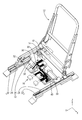
- FIG. 1 is a front perspective view of a vehicle seat.
- FIG. 2 is a front perspective view of the vehicle seat in a state where a part of the skeleton part of the vehicle seat is removed.
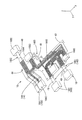
- FIG. 3 is a front perspective view of the skeleton frame in a state where the wire harness is fixed.
- FIG. 4 is a plan view of the skeleton frame in a state where the wire harness is fixed.
- FIG. 5 is a rear perspective view of the skeleton frame in a state where the wire harness is fixed, as seen from the bottom surface.
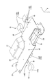
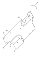
- FIG. 6 is a front perspective view of the wire harness.
- FIG. 7 is a front perspective view of the skeleton frame.
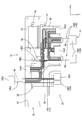
- FIG. 8 is a diagram illustrating a structure in which the seat member is fixed to the skeleton frame by the clip member.
- the wire harness of the present disclosure is (1) A wire harness attached to a frame arranged in the lower part of a vehicle seat, which includes a seat member attached to the frame and an electric wire fixed to the seat member.
- the frame includes a pair of slide portions on which the vehicle seat is placed and slides the vehicle seat, and a skeleton frame connecting the pair of slide portions.
- the seat member is the skeleton frame. It is preferable to be attached to.
- a slide motor that slides the vehicle seat may be attached to the skeleton frame.
- the area of the seat member can be increased as compared with the case where the seat member is fixed to the side surface of the slide portion or the like.
- Many electric wires can be fixed to the seat member.
- the skeleton frame includes a flat surface portion forming a flat surface, and the seat member is attached to the flat surface portion.
- the seat member By providing a flat portion to which the seat member can be attached to the skeleton frame, the seat member can be easily attached to the skeleton frame, and the wiring process of the wire harness can be further simplified.
- the seat member is provided with a first fixing hole, and a second fixing hole is provided at a position of the skeleton frame corresponding to the first fixing hole on the flat surface portion. It is preferable that a clip member for fixing the seat member to the skeleton frame is inserted into the first fixing hole and the second fixing hole.
- the electric wire includes a fixed portion fixed to the seat member and a separated portion separated from the seat member and connected to a connector, and the separated portion protects the separated portion.
- the exterior member is attached.
- the separated portion By providing a separated portion, it is possible to connect the device arranged at a position separated from the seat member and the electric wire. Further, by attaching an exterior member to the separated portion, the separated portion can be protected when a device or the like that may come into contact with the periphery of the separated portion is provided.
- a fixed structure of the wire harness including the wire harness according to any one of (1) to (5) above and a frame arranged at the lower part of the vehicle seat may be used.
- the wire harness 10 of the present disclosure will be described with reference to FIGS. 1 to 8.
- the wire harness 10 is connected to equipment and the like related to the vehicle seat 12 (for example, a slide motor 38, and a seat heater, a blower, a seat memory ECU, a reclining motor, an operation switch, etc., which are not shown).
- the X direction in FIG. 1 will be described as the right side in the left-right direction
- the Y direction will be described as the front side in the front-rear direction
- the Z direction will be described as the upper side in the vertical direction.
- the wire harness 10 includes a plurality of electric wires 14, a plurality of connectors 16, and a wire harness fixing structure 20 fixed to a frame 18 arranged under the vehicle seat 12. , Is configured.
- the cushion portion of the vehicle seat 12 is not shown, and only the skeleton portion is shown.
- the frame 18 is made of a metal member, and includes a pair of rail portions 22, a pair of slide portions 24, and a skeleton frame 26.
- the pair of rail portions 22 are formed so as to extend in the front-rear direction, and are arranged at intervals in the left-right direction.
- a pair of slide portions 24 are attached to the pair of rail portions 22.
- the slide portion 24 has a rectangular tubular shape that is long in the front-rear direction, and can slide on the rail portion 22 in the front-rear direction.
- a vehicle seat 12 is fixed to the upper surface of the slide portion 24. As a result, the vehicle seat 12 can slide in the front-rear direction.
- the skeleton frame 26 is formed so as to extend in the left-right direction, and connects a pair of slide portions 24. As shown in FIGS. 3 to 5 and 7, the skeleton frame 26 includes a first flat surface portion 30 (an example of a flat surface portion), a second flat surface portion 32 (an example of a flat surface portion), and a motor accommodating portion 34. And is configured with.
- first flat surface portion 30 has a long flat plate shape in the left-right direction, and as shown in FIG. 2, both left and right end portions of the first flat surface portion 30 are left and right slide portions. It is fixed at 24. As a result, the skeleton frame 26 is displaced in the front-rear direction in accordance with the slide of the vehicle seat 12.
- the second flat surface portion 32 has a flat plate shape parallel to the first flat surface portion 30, and is connected to the first flat surface portion 30 via the inclined surface portion 36 that is inclined downward.
- the motor accommodating portion 34 has a shape recessed downward from the first flat surface portion 30.
- the motor accommodating portion 34 accommodates a slide motor 38 that slides the vehicle seat 12.
- the first plane portion 30 and the second plane portion 32 of the skeleton frame 26 have a plurality of second fixing holes 42 for fixing the sheet member 40 described later to the skeleton frame 26. Is provided with an opening.
- the wire harness fixing structure 20 includes a seat member 40.
- the sheet member 40 is made of a non-woven fabric.
- a part of the plurality of electric wires 14 is ultrasonically welded to the surface side of the seat member 40 and fixed to the seat member 40.
- the seat member 40 is attached and fixed on the skeleton frame 26 over the first flat surface portion 30, the second flat surface portion 32, and the inclined surface portion 36.
- the sheet member 40 is attached to the skeleton frame 26 with double-sided tape.
- the seat member 40 is provided with a plurality of first fixing holes 44 opened.
- Each of the first fixing holes 44 in the seat member 40 is provided at a position corresponding to each of the second fixing holes 42 in the skeleton frame 26 in a state where the seat member 40 is attached to the skeleton frame 26.
- the plurality of connectors 16 include an on-frame connector 16A arranged to face the skeleton frame 26 and a separation connector 16B arranged at a position separated from the skeleton frame 26. It is configured. Terminals (not shown) are housed inside the on-frame connector 16A and the separation connector 16B, and the terminal of each electric wire 14 is connected to the terminal housed in each connector 16.
- three on-frame connectors 16A are arranged on the first flat surface portion 30 of the skeleton frame 26, and two are arranged on the second flat surface portion 32.
- the first frame upper connector 16A1 and the second frame upper connector 16A2 arranged on the second flat surface portion 32 have a WtoW (Wire to Wire) connector (not shown) of the vehicle body side harness. Is connected. Further, among the frame upper connectors 16A, the WtoW (Wire to Wire) connector of the vehicle body side harness is connected to the third frame upper connector 16A3 arranged at the front end portion on the first flat surface portion 30.
- the on-frame connector 16A4 arranged at the rear end on the first flat surface portion 30 has a wire harness (wire harness) arranged at the rear of the vehicle seat 12.
- the WtoW connector (not shown) of the seat back side harness) is connected.
- a connector (not shown) of an operation switch of the vehicle seat 12 is connected to the connector 16A5 on the fifth frame arranged at the front end portion on the first flat surface portion 30.
- the plurality of separation connectors 16B are connected to co-devices arranged at positions away from the skeleton frame 26 via the separation portion 14B of the electric wire 14 described later.
- a pair of left and right first separation connectors 16B1 located in front of the skeleton frame 26 are connected to a seat memory ECU (Electronic Control Unit) (not shown).
- a seat memory ECU Electronic Control Unit
- the second separation connector 16B2 located behind the skeleton frame 26 is connected to a unit (not shown) that controls a seat heater or the like.
- the third separation connector 16B3 located above the skeleton frame 26 is connected to the slide motor 38.
- the third separation connector 16B3 is not connected to the slide motor 38.
- the plurality of electric wires 14 have a fixed portion 14A that is fused and fixed to the seat member 40, and a separating portion 14B that is separated from the seat member 40 and connected to the separating connector 16B. have.
- the fixing portion 14A is fixed side by side on the seat member 40 for each electric wire bundle connected to each connector 16.
- the separation portion 14B includes a pair of first separation portions 14B1, a second separation portion 14B2, and a third separation portion 14B3.
- the pair of first separation portions 14B1 extend from the front end edge of the first plane portion 30 of the skeleton frame 26 toward the pair of first separation connectors 16B1, and the terminals thereof are housed in the pair of first separation connectors 16B1. It is connected to the terminal (not shown).
- the second separation portion 14B2 extends from the rear end edge of the first plane portion 30 of the skeleton frame 26 toward the second separation connector 16B2, and the terminal thereof is a terminal housed in the second separation connector 16B2 (shown). Is connected to.
- the third separation portion 14B3 extends upward from the trailing edge of the first plane portion 30 of the skeleton frame 26, and its terminal is connected to a terminal (not shown) accommodated in the third separation connector 16B3. ing.
- an exterior member 48 is attached to each of the separated portions 14B (first separated portion 14B1, second separated portion 14B2, and third separated portion 14B3).
- the exterior member 48 is made of a non-woven fabric, and is fixed in a wound state so as to cover the outer periphery of each of the separated portions 14B.
- a sheet member (not shown) is further attached to the skeleton frame 26 from above so as to cover the electric wire 14 in a state where the sheet member 40 to which the electric wire 14 is fused is attached (the state shown in FIG. 3). Be done. As a result, the electric wires 14 fused to the flat surfaces 30 and 32 can be made invisible from the outside, and the electric wires 14 can be protected.
- the wire harness 10 of the present embodiment is a wire harness 10 attached to a frame 18 arranged in the lower part of the vehicle seat 12, and includes a seat member 40 attached to the frame 18 and an electric wire 14 fixed to the seat member 40. , Equipped with.
- the seat member 40 to which the electric wire 14 is fixed to the frame 18 arranged at the lower part of the vehicle seat 12, for example, a corrugated tube through which the electric wire is inserted can be seated as in the conventional case.
- the wiring space can be reduced compared to the configuration in which the wiring is arranged at the bottom of the.
- the wire harness 10 can be arranged in a small space. Further, since it is not necessary to route the wire harness 10 while avoiding the devices provided in the lower part of the seat, the wiring process of the wire harness 10 can be simplified.
- the frame 18 includes a pair of slide portions 24 on which the vehicle seat 12 is mounted and slides the vehicle seat 12, and a skeleton frame 26 connecting the pair of slide portions 24.
- the seat member 40 is a skeleton frame. It is configured to be attached to 26.
- a slide motor 38 that slides the vehicle seat 12 may be attached to the skeleton frame 26.
- the area of the seat member 40 can be increased as compared with the case where the seat member is fixed to the side surface of the slide portion or the like. Therefore, more electric wires 14 can be fixed to the seat member 40. Further, since a large current is required to slide the vehicle seat 12, the present embodiment in which more electric wires 14 can be fixed to the seat member 40 is particularly effective.
- the skeleton frame 26 includes flat surface portions 30 and 32 forming a flat surface, and the seat member 40 is configured to be attached to the flat surface portions 30 and 32.
- the seat member 40 can be easily attached to the skeleton frame 26 by the work of laying the sheet member 40 on the flat surface portions 30 and 32 and spreading the sheet member 40. This makes it possible to further simplify the wiring process of the wire harness 10.
- the seat member 40 is provided with a first fixing hole 44, and a second fixing hole 42 is provided at a position corresponding to the first fixing hole 44 in the flat surface portions 30 and 32 in the skeleton frame 26.
- a clip member 46 for fixing the seat member 40 to the skeleton frame 26 is inserted into the first fixing hole 44 and the second fixing hole 42.
- the electric wire 14 includes a fixed portion 14A fixed to the seat member 40 and a separating portion 14B separated from the seat member 40 and connected to the connector, and the separating portion 14B is provided with the separating portion 14B.
- the exterior member 48 to be protected is attached.
- the separated portion 14B By providing the separated portion 14B, it is possible to connect the equipment arranged at a position separated from the seat member 40 and the electric wire 14. Further, by attaching the exterior member 48 to the separated portion 14B, the separated portion 14B can be protected when a device or the like that may come into contact with the periphery of the separated portion 14B is provided.
- the wire harness fixing structure 20 includes a wire harness 10 and a frame 18 arranged at the lower part of the vehicle seat 12.
- the seat member 40 is made of a non-woven fabric, but the present invention is not limited to this.
- the sheet member may be a woven fabric, or may be a synthetic resin processed into a sheet shape.
- the seat member 40 is fixed to the skeleton frame 26 by inserting the clip member 46 into the first fixing hole 44 and the second fixing hole 42, but the present invention is limited to this.
- the clip member may be a spring clip, and the spring clip may sandwich the seat member and the skeleton frame to fix the seat member to the skeleton frame.
- the exterior member 48 of the separated portion 14B is made of a non-woven fabric like the seat member 40, but the present invention is not limited to this, and other types of exterior members such as corrugated tubes and the like are used. It may be configured to be. Further, if there is no possibility of contacting the periphery of the path of the separated portion, the exterior member may not be set in the separated portion.
- the electric wire 14 is fixed to the seat member 40 by ultrasonic welding, but the present invention is not limited to this.
- the electric wire may be fixed to the sheet member with an adhesive.
- Wire harness 12 Vehicle seat 14: Electric wire 14A: Fixed part 14B: Separation part 14B1: First separation part 14B2: Second separation part 14B3: Third separation part 16: Connector 16A: On-frame connector 16A1: First frame Upper connector 16A2: 2nd frame upper connector 16A3: 3rd frame upper connector 16A4: 4th frame upper connector 16A5: 5th frame upper connector 16B: Separated connector 16B1: 1st separated connector 16B2: 2nd separated connector 16B3: 3rd Separation connector 18: Frame 20: Wire harness fixing structure 22: Rail portion 24: Slide portion 26: Frame frame 30: First flat portion (flat portion) 32: Second flat surface part (flat surface part) 34: Motor accommodating portion 36: Inclined surface portion 38: Slide motor 40: Seat member 42: Second fixing hole 44: First fixing hole 46: Clip member 48: Exterior member
Landscapes
- Engineering & Computer Science (AREA)
- Mechanical Engineering (AREA)
- Aviation & Aerospace Engineering (AREA)
- Transportation (AREA)
- Civil Engineering (AREA)
- Architecture (AREA)
- Structural Engineering (AREA)
- Computer Networks & Wireless Communication (AREA)
- Seats For Vehicles (AREA)
- Insulated Conductors (AREA)
- Details Of Indoor Wiring (AREA)
- Installation Of Indoor Wiring (AREA)
- Electric Cable Arrangement Between Relatively Moving Parts (AREA)
Priority Applications (2)
| Application Number | Priority Date | Filing Date | Title |
|---|---|---|---|
| CN202080073203.7A CN114555425A (zh) | 2019-11-06 | 2020-10-20 | 配线线束以及配线线束的固定构造 |
| US17/772,989 US12384309B2 (en) | 2019-11-06 | 2020-10-20 | Wire harness and wire harness fixing structure |
Applications Claiming Priority (2)
| Application Number | Priority Date | Filing Date | Title |
|---|---|---|---|
| JP2019-201351 | 2019-11-06 | ||
| JP2019201351A JP7306227B2 (ja) | 2019-11-06 | 2019-11-06 | ワイヤーハーネスおよびワイヤーハーネスの固定構造 |
Publications (1)
| Publication Number | Publication Date |
|---|---|
| WO2021090673A1 true WO2021090673A1 (ja) | 2021-05-14 |
Family
ID=75849716
Family Applications (1)
| Application Number | Title | Priority Date | Filing Date |
|---|---|---|---|
| PCT/JP2020/039366 Ceased WO2021090673A1 (ja) | 2019-11-06 | 2020-10-20 | ワイヤーハーネスおよびワイヤーハーネスの固定構造 |
Country Status (4)
| Country | Link |
|---|---|
| US (1) | US12384309B2 (enExample) |
| JP (1) | JP7306227B2 (enExample) |
| CN (1) | CN114555425A (enExample) |
| WO (1) | WO2021090673A1 (enExample) |
Cited By (2)
| Publication number | Priority date | Publication date | Assignee | Title |
|---|---|---|---|---|
| CN116872808A (zh) * | 2023-08-21 | 2023-10-13 | 梅赛德斯-奔驰集团股份公司 | 一种坐垫骨架结构、车辆座椅及车辆 |
| WO2024128074A1 (ja) * | 2022-12-13 | 2024-06-20 | 株式会社オートネットワーク技術研究所 | ワイヤハーネスの配索構造及びワイヤハーネス |
Citations (3)
| Publication number | Priority date | Publication date | Assignee | Title |
|---|---|---|---|---|
| JP2010018106A (ja) * | 2008-07-09 | 2010-01-28 | Yazaki Corp | 配線盤、電動シート、およびワイヤハーネス配索方法 |
| JP2010036667A (ja) * | 2008-08-01 | 2010-02-18 | Toyota Boshoku Corp | ボード |
| JP2015215077A (ja) * | 2014-05-13 | 2015-12-03 | 株式会社パイオラックス | クリップ |
Family Cites Families (18)
| Publication number | Priority date | Publication date | Assignee | Title |
|---|---|---|---|---|
| JPH01148947U (enExample) * | 1988-04-06 | 1989-10-16 | ||
| JPH11198690A (ja) * | 1998-01-09 | 1999-07-27 | Furukawa Electric Co Ltd:The | 車両用電動シート装置の配線部材 |
| JP2002019545A (ja) * | 2000-07-05 | 2002-01-23 | Daihatsu Motor Co Ltd | 自動車におけるハーネス等の配置構造およびその固定具 |
| JP3868749B2 (ja) * | 2001-03-08 | 2007-01-17 | 矢崎総業株式会社 | 車両シート用ワイヤハーネス |
| US7172244B2 (en) * | 2003-06-26 | 2007-02-06 | Lear Corporation | Vehicle seat assembly having a vehicle occupant sensing system and a seat cushion insert positioned therein |
| JP2007112181A (ja) * | 2005-10-18 | 2007-05-10 | Furukawa Electric Co Ltd:The | 車両シート用フラットハーネス組立体及びフラットハーネス配索方法 |
| JP2007181296A (ja) * | 2005-12-27 | 2007-07-12 | Yazaki Corp | ワイヤハーネス配索構造 |
| JP2007212196A (ja) * | 2006-02-07 | 2007-08-23 | Toyota Boshoku Corp | 車両シート用荷重検出装置 |
| JP2006199288A (ja) * | 2006-03-03 | 2006-08-03 | Furukawa Electric Co Ltd:The | 車両用パワーシートの配線方法 |
| JP4827590B2 (ja) * | 2006-04-05 | 2011-11-30 | 矢崎総業株式会社 | ワイヤハーネスの配索構造 |
| JP5424447B2 (ja) * | 2008-07-15 | 2014-02-26 | 矢崎総業株式会社 | ワイヤハーネス |
| JP5248436B2 (ja) * | 2009-07-22 | 2013-07-31 | 矢崎総業株式会社 | ワイヤハーネス配索装置 |
| JP5755858B2 (ja) * | 2010-09-02 | 2015-07-29 | 矢崎総業株式会社 | ワイヤハーネス配索構造 |
| JP5644542B2 (ja) * | 2011-01-26 | 2014-12-24 | 株式会社オートネットワーク技術研究所 | ワイヤハーネス |
| CN102862497B (zh) * | 2012-10-16 | 2014-12-10 | 沈阳延锋江森座椅有限责任公司 | 一种长行程座椅的供电结构 |
| JP6459732B2 (ja) * | 2015-04-07 | 2019-01-30 | トヨタ紡織株式会社 | 乗物用シート |
| JP6827891B2 (ja) * | 2017-07-24 | 2021-02-10 | 株式会社タチエス | シートフレーム |
| JP6356882B1 (ja) * | 2017-07-31 | 2018-07-11 | テイ・エス テック株式会社 | シートへのセンサーの配置構造 |
-
2019
- 2019-11-06 JP JP2019201351A patent/JP7306227B2/ja active Active
-
2020
- 2020-10-20 US US17/772,989 patent/US12384309B2/en active Active
- 2020-10-20 WO PCT/JP2020/039366 patent/WO2021090673A1/ja not_active Ceased
- 2020-10-20 CN CN202080073203.7A patent/CN114555425A/zh active Pending
Patent Citations (3)
| Publication number | Priority date | Publication date | Assignee | Title |
|---|---|---|---|---|
| JP2010018106A (ja) * | 2008-07-09 | 2010-01-28 | Yazaki Corp | 配線盤、電動シート、およびワイヤハーネス配索方法 |
| JP2010036667A (ja) * | 2008-08-01 | 2010-02-18 | Toyota Boshoku Corp | ボード |
| JP2015215077A (ja) * | 2014-05-13 | 2015-12-03 | 株式会社パイオラックス | クリップ |
Cited By (4)
| Publication number | Priority date | Publication date | Assignee | Title |
|---|---|---|---|---|
| WO2024128074A1 (ja) * | 2022-12-13 | 2024-06-20 | 株式会社オートネットワーク技術研究所 | ワイヤハーネスの配索構造及びワイヤハーネス |
| JP2024084212A (ja) * | 2022-12-13 | 2024-06-25 | 株式会社オートネットワーク技術研究所 | ワイヤハーネスの配索構造及びワイヤハーネス |
| JP7768108B2 (ja) | 2022-12-13 | 2025-11-12 | 株式会社オートネットワーク技術研究所 | ワイヤハーネスの配索構造及びワイヤハーネス |
| CN116872808A (zh) * | 2023-08-21 | 2023-10-13 | 梅赛德斯-奔驰集团股份公司 | 一种坐垫骨架结构、车辆座椅及车辆 |
Also Published As
| Publication number | Publication date |
|---|---|
| CN114555425A (zh) | 2022-05-27 |
| JP2021077474A (ja) | 2021-05-20 |
| US12384309B2 (en) | 2025-08-12 |
| JP7306227B2 (ja) | 2023-07-11 |
| US20240149803A1 (en) | 2024-05-09 |
Similar Documents
| Publication | Publication Date | Title |
|---|---|---|
| JP6889715B2 (ja) | 車両用回路体 | |
| JP7056544B2 (ja) | ワイヤハーネス配索部材 | |
| JPH11178174A (ja) | 電線保持具 | |
| WO2021090673A1 (ja) | ワイヤーハーネスおよびワイヤーハーネスの固定構造 | |
| JP6790838B2 (ja) | コネクタ | |
| JP6830466B2 (ja) | ワイヤハーネス | |
| JP6889367B2 (ja) | 乗物用シート | |
| JP7779369B2 (ja) | ワイヤーハーネス | |
| CN105531883A (zh) | 连接器 | |
| CN112384410B (zh) | 线束及线束的装配结构 | |
| US4936631A (en) | Vehicular seat | |
| JP5264252B2 (ja) | 車両シートにおけるワイヤハーネス配索構造 | |
| CN102834978B (zh) | 节点连接器组件 | |
| JP3895663B2 (ja) | コネクタホルダ | |
| JP2006344419A (ja) | コネクタ嵌合具及びコネクタ嵌合方法 | |
| JP2006158151A (ja) | ワイヤハーネスの配索構造 | |
| JP2018010823A (ja) | 端子台 | |
| JP2016152717A (ja) | 電源分配装置 | |
| EP2072319A1 (en) | Support for control units, in particular for vehicle control units and wire bundles | |
| JP2020142559A (ja) | 車両用シート | |
| JP6185313B2 (ja) | 乗物用シートの電気配線配索構造 | |
| US20250174973A1 (en) | Wire harness | |
| JP2009248677A (ja) | 車両シートにおけるワイヤハーネス配索構造 | |
| JP2023183820A (ja) | 部品結合構造及びワイヤハーネス | |
| JPH10194011A (ja) | 中央配置型電気接続箱 |
Legal Events
| Date | Code | Title | Description |
|---|---|---|---|
| 121 | Ep: the epo has been informed by wipo that ep was designated in this application |
Ref document number: 20883686 Country of ref document: EP Kind code of ref document: A1 |
|
| WWE | Wipo information: entry into national phase |
Ref document number: 17772989 Country of ref document: US |
|
| NENP | Non-entry into the national phase |
Ref country code: DE |
|
| 122 | Ep: pct application non-entry in european phase |
Ref document number: 20883686 Country of ref document: EP Kind code of ref document: A1 |
|
| WWG | Wipo information: grant in national office |
Ref document number: 17772989 Country of ref document: US |