JP2006158151A - ワイヤハーネスの配索構造 - Google Patents
ワイヤハーネスの配索構造 Download PDFInfo
- Publication number
- JP2006158151A JP2006158151A JP2004348426A JP2004348426A JP2006158151A JP 2006158151 A JP2006158151 A JP 2006158151A JP 2004348426 A JP2004348426 A JP 2004348426A JP 2004348426 A JP2004348426 A JP 2004348426A JP 2006158151 A JP2006158151 A JP 2006158151A
- Authority
- JP
- Japan
- Prior art keywords
- wire harness
- branch line
- branch
- connection box
- line
- Prior art date
- Legal status (The legal status is an assumption and is not a legal conclusion. Google has not performed a legal analysis and makes no representation as to the accuracy of the status listed.)
- Pending
Links
Images

Classifications
-
- B—PERFORMING OPERATIONS; TRANSPORTING
- B60—VEHICLES IN GENERAL
- B60R—VEHICLES, VEHICLE FITTINGS, OR VEHICLE PARTS, NOT OTHERWISE PROVIDED FOR
- B60R16/00—Electric or fluid circuits specially adapted for vehicles and not otherwise provided for; Arrangement of elements of electric or fluid circuits specially adapted for vehicles and not otherwise provided for
- B60R16/02—Electric or fluid circuits specially adapted for vehicles and not otherwise provided for; Arrangement of elements of electric or fluid circuits specially adapted for vehicles and not otherwise provided for electric constitutive elements
- B60R16/0207—Wire harnesses
- B60R16/0215—Protecting, fastening and routing means therefor
Abstract
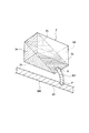
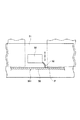
【解決手段】 ワイヤハーネスWHの幹線W1が車体パネル1に固定された状態で配索され、ワイヤハーネスWHの幹線W1より分岐された枝線W2に電気接続箱2が接続され、この電気接続箱2が車体内の所定の収容位置に設置されるワイヤハーネスの配索構造において、枝線W2を電気接続箱2の底面2aに沿って配索し、枝線W2の先端Sと電気接続箱2の底面2aとを枝線W2の分岐位置Pの最短長より長くなる位置で接続した。
【選択図】 図1
Description
W1 幹線
W2 枝線
P 分岐位置
1 車体パネル
2 電気接続箱(取付部品)
2a 底面(下側の面)
2d 正面(一面)
Claims (2)
- ワイヤハーネスの幹線が車体パネルに固定された状態で配索され、前記ワイヤハーネスの幹線より分岐された枝線に取付部品が接続され、この取付部品が車体内の所定の収容位置に設置されるワイヤハーネスの配索構造において、
前記枝線と前記取付部品とを、その取り付け状態で該枝線の分岐位置の最短長より長くなる位置で、かつ該分岐位置の最短位置から真上に延びる該取付部品の一面を除く位置で接続したことを特徴とするワイヤハーネスの配索構造。 - 請求項1記載のワイヤハーネスの配索構造であって、
前記枝線を前記取付部品の下側の面に沿って配索することによって前記分岐位置から該下側の面の最短長より長くなる位置まで導いたことを特徴とするワイヤハーネスの配索構造。
Priority Applications (3)
| Application Number | Priority Date | Filing Date | Title |
|---|---|---|---|
| JP2004348426A JP2006158151A (ja) | 2004-12-01 | 2004-12-01 | ワイヤハーネスの配索構造 |
| EP05026150.2A EP1666310B1 (en) | 2004-12-01 | 2005-11-30 | Wire harness installation structure |
| US11/290,421 US7179997B2 (en) | 2004-12-01 | 2005-12-01 | Wire harness installation structure |
Applications Claiming Priority (1)
| Application Number | Priority Date | Filing Date | Title |
|---|---|---|---|
| JP2004348426A JP2006158151A (ja) | 2004-12-01 | 2004-12-01 | ワイヤハーネスの配索構造 |
Publications (1)
| Publication Number | Publication Date |
|---|---|
| JP2006158151A true JP2006158151A (ja) | 2006-06-15 |
Family
ID=35788140
Family Applications (1)
| Application Number | Title | Priority Date | Filing Date |
|---|---|---|---|
| JP2004348426A Pending JP2006158151A (ja) | 2004-12-01 | 2004-12-01 | ワイヤハーネスの配索構造 |
Country Status (3)
| Country | Link |
|---|---|
| US (1) | US7179997B2 (ja) |
| EP (1) | EP1666310B1 (ja) |
| JP (1) | JP2006158151A (ja) |
Families Citing this family (5)
| Publication number | Priority date | Publication date | Assignee | Title |
|---|---|---|---|---|
| JP2007116782A (ja) * | 2005-10-18 | 2007-05-10 | Yazaki Corp | 配索装置 |
| JP2012111406A (ja) * | 2010-11-26 | 2012-06-14 | Sumitomo Wiring Syst Ltd | ワイヤーハーネス配索構造部およびプロテクタ |
| JP6644824B2 (ja) * | 2018-04-04 | 2020-02-12 | 矢崎総業株式会社 | 分岐回路体及び電線の分岐方法 |
| JP6691164B2 (ja) * | 2018-04-04 | 2020-04-28 | 矢崎総業株式会社 | 分岐回路体及び電線の分岐方法 |
| JP7153037B2 (ja) * | 2020-01-17 | 2022-10-13 | 矢崎総業株式会社 | ワイヤハーネス |
Family Cites Families (19)
| Publication number | Priority date | Publication date | Assignee | Title |
|---|---|---|---|---|
| US1837962A (en) * | 1928-07-03 | 1931-12-22 | Gen Electric | Manufacture of electrical apparatus |
| US2299140A (en) * | 1939-06-28 | 1942-10-20 | Union Carbide & Carbon Corp | Wire harness |
| US3128214A (en) * | 1959-04-06 | 1964-04-07 | Ling Temco Vought Inc | Method of making multiconductor cable |
| US3055971A (en) * | 1959-09-25 | 1962-09-25 | Gen Motors Corp | Panel wiring assemblies |
| US3984622A (en) * | 1976-02-20 | 1976-10-05 | Southern Weaving Company | Multi-conductor cable harness with woven breakout cover and method of making same |
| US4280062A (en) * | 1979-08-22 | 1981-07-21 | Douglas Dynamics Inc. | Auxiliary light wiring harness |
| JP2913951B2 (ja) * | 1991-09-26 | 1999-06-28 | 住友電装株式会社 | ドア用ワイヤーハーネスの配索方法 |
| JPH0546607U (ja) * | 1991-12-04 | 1993-06-22 | 富士重工業株式会社 | ワイヤハーネスの中間口出し装置 |
| JP3312537B2 (ja) | 1994-09-14 | 2002-08-12 | 住友電装株式会社 | 自動車用分岐接続装置 |
| JP3169041B2 (ja) | 1994-10-06 | 2001-05-21 | 矢崎総業株式会社 | 電気接続箱による電線保持方法およびその構造 |
| JP3009024B2 (ja) | 1995-04-14 | 2000-02-14 | 矢崎総業株式会社 | 分岐ワイヤーハーネスの支持構造 |
| JP3022256B2 (ja) | 1995-06-13 | 2000-03-15 | 住友電装株式会社 | 電気接続箱の仮保持機構 |
| JP3031204B2 (ja) | 1995-06-28 | 2000-04-10 | 住友電装株式会社 | 電気接続箱の仮保持機構および該電気接続箱の取付方法 |
| US5994645A (en) * | 1996-06-14 | 1999-11-30 | Sumitomo Wiring Systems, Ltd. | Wiring harness arranging construction |
| US5954538A (en) * | 1997-07-28 | 1999-09-21 | Grand General Accessories Manufacturing Inc. | Set of harnesses for interconnecting a plurality of ornamental light fixtures in a vehicle |
| JP3489724B2 (ja) * | 1998-03-16 | 2004-01-26 | 矢崎総業株式会社 | ワイヤーハーネス |
| JP2000038094A (ja) * | 1998-07-21 | 2000-02-08 | Harness Syst Tech Res Ltd | 車両のインストゥルメントパネルにおける配線構造 |
| US6291770B1 (en) * | 1999-05-14 | 2001-09-18 | Leoni Wiring Systems, Inc. | Wiring system and method therefor |
| US6621688B1 (en) * | 2002-06-26 | 2003-09-16 | Alcoa Fujikura Limited | Electrical distribution system having integral junction box for instrument panel application |
-
2004
- 2004-12-01 JP JP2004348426A patent/JP2006158151A/ja active Pending
-
2005
- 2005-11-30 EP EP05026150.2A patent/EP1666310B1/en active Active
- 2005-12-01 US US11/290,421 patent/US7179997B2/en active Active
Also Published As
| Publication number | Publication date |
|---|---|
| US20060141810A1 (en) | 2006-06-29 |
| US7179997B2 (en) | 2007-02-20 |
| EP1666310B1 (en) | 2013-06-26 |
| EP1666310A1 (en) | 2006-06-07 |
Similar Documents
| Publication | Publication Date | Title |
|---|---|---|
| JP6160469B2 (ja) | スライドシート用ワイヤハーネスの配索装置 | |
| JP2002362254A (ja) | 車両用機器の取付構造 | |
| JP2008061410A (ja) | 電気接続箱 | |
| JP5446043B2 (ja) | インストルメントパネル構造 | |
| JP2006158151A (ja) | ワイヤハーネスの配索構造 | |
| JP2011101511A (ja) | ジャンクションブロック構造体 | |
| JP2021114401A (ja) | ワイヤハーネス | |
| JP5158943B2 (ja) | 電気接続箱内における電線の配索構造 | |
| JP3606090B2 (ja) | 自動車の配線構造 | |
| JP6883921B2 (ja) | ハーネス配索構造 | |
| JP6222694B2 (ja) | 車両用コネクタ固定構造 | |
| JP2018001905A (ja) | 内装部材 | |
| WO2016039446A1 (ja) | 電気接続箱 | |
| JP2009248676A (ja) | 車両シートにおけるワイヤハーネス配索構造 | |
| JP2018191384A (ja) | 水切プロテクタおよびそれを用いたワイヤハーネスの水切構造 | |
| JP7399567B2 (ja) | ハーネス配索構造 | |
| JP2024012059A (ja) | ワイヤハーネスの固定構造 | |
| JP4890929B2 (ja) | 作業機械の電装品収納構造 | |
| JP2007215322A (ja) | ワイヤハーネスの配索構造 | |
| JP4196670B2 (ja) | ワイヤハーネス用プロテクタ | |
| KR0130470Y1 (ko) | 차량 의자의 전기배선구조 | |
| JP6576671B2 (ja) | 電気接続箱 | |
| JP2009295527A (ja) | ワイヤハーネス | |
| JP2022180007A (ja) | 機能追加用電気配線、及びワイヤハーネス | |
| JP2021114400A (ja) | ワイヤハーネス |
Legal Events
| Date | Code | Title | Description |
|---|---|---|---|
| A621 | Written request for application examination |
Free format text: JAPANESE INTERMEDIATE CODE: A621 Effective date: 20070620 |
|
| A131 | Notification of reasons for refusal |
Free format text: JAPANESE INTERMEDIATE CODE: A131 Effective date: 20080603 |
|
| A521 | Written amendment |
Free format text: JAPANESE INTERMEDIATE CODE: A523 Effective date: 20080804 |
|
| A02 | Decision of refusal |
Free format text: JAPANESE INTERMEDIATE CODE: A02 Effective date: 20080826 |
|
| A521 | Written amendment |
Free format text: JAPANESE INTERMEDIATE CODE: A523 Effective date: 20081027 |
|
| A911 | Transfer of reconsideration by examiner before appeal (zenchi) |
Free format text: JAPANESE INTERMEDIATE CODE: A911 Effective date: 20081031 |
|
| A912 | Removal of reconsideration by examiner before appeal (zenchi) |
Free format text: JAPANESE INTERMEDIATE CODE: A912 Effective date: 20081205 |
|
| A521 | Written amendment |
Free format text: JAPANESE INTERMEDIATE CODE: A523 Effective date: 20100726 |