WO2021010107A1 - 冷凍装置、温度センサ取付管及び温度センサ取付構造 - Google Patents
冷凍装置、温度センサ取付管及び温度センサ取付構造 Download PDFInfo
- Publication number
- WO2021010107A1 WO2021010107A1 PCT/JP2020/024671 JP2020024671W WO2021010107A1 WO 2021010107 A1 WO2021010107 A1 WO 2021010107A1 JP 2020024671 W JP2020024671 W JP 2020024671W WO 2021010107 A1 WO2021010107 A1 WO 2021010107A1
- Authority
- WO
- WIPO (PCT)
- Prior art keywords
- temperature sensor
- sensor mounting
- temperature side
- surface area
- large surface
- Prior art date
Links
Images


Classifications
-
- F—MECHANICAL ENGINEERING; LIGHTING; HEATING; WEAPONS; BLASTING
- F25—REFRIGERATION OR COOLING; COMBINED HEATING AND REFRIGERATION SYSTEMS; HEAT PUMP SYSTEMS; MANUFACTURE OR STORAGE OF ICE; LIQUEFACTION SOLIDIFICATION OF GASES
- F25B—REFRIGERATION MACHINES, PLANTS OR SYSTEMS; COMBINED HEATING AND REFRIGERATION SYSTEMS; HEAT PUMP SYSTEMS
- F25B49/00—Arrangement or mounting of control or safety devices
- F25B49/02—Arrangement or mounting of control or safety devices for compression type machines, plants or systems
- F25B49/022—Compressor control arrangements
-
- F—MECHANICAL ENGINEERING; LIGHTING; HEATING; WEAPONS; BLASTING
- F25—REFRIGERATION OR COOLING; COMBINED HEATING AND REFRIGERATION SYSTEMS; HEAT PUMP SYSTEMS; MANUFACTURE OR STORAGE OF ICE; LIQUEFACTION SOLIDIFICATION OF GASES
- F25B—REFRIGERATION MACHINES, PLANTS OR SYSTEMS; COMBINED HEATING AND REFRIGERATION SYSTEMS; HEAT PUMP SYSTEMS
- F25B41/00—Fluid-circulation arrangements
- F25B41/40—Fluid line arrangements
-
- F—MECHANICAL ENGINEERING; LIGHTING; HEATING; WEAPONS; BLASTING
- F25—REFRIGERATION OR COOLING; COMBINED HEATING AND REFRIGERATION SYSTEMS; HEAT PUMP SYSTEMS; MANUFACTURE OR STORAGE OF ICE; LIQUEFACTION SOLIDIFICATION OF GASES
- F25B—REFRIGERATION MACHINES, PLANTS OR SYSTEMS; COMBINED HEATING AND REFRIGERATION SYSTEMS; HEAT PUMP SYSTEMS
- F25B39/00—Evaporators; Condensers
-
- F—MECHANICAL ENGINEERING; LIGHTING; HEATING; WEAPONS; BLASTING
- F25—REFRIGERATION OR COOLING; COMBINED HEATING AND REFRIGERATION SYSTEMS; HEAT PUMP SYSTEMS; MANUFACTURE OR STORAGE OF ICE; LIQUEFACTION SOLIDIFICATION OF GASES
- F25B—REFRIGERATION MACHINES, PLANTS OR SYSTEMS; COMBINED HEATING AND REFRIGERATION SYSTEMS; HEAT PUMP SYSTEMS
- F25B49/00—Arrangement or mounting of control or safety devices
-
- F—MECHANICAL ENGINEERING; LIGHTING; HEATING; WEAPONS; BLASTING
- F25—REFRIGERATION OR COOLING; COMBINED HEATING AND REFRIGERATION SYSTEMS; HEAT PUMP SYSTEMS; MANUFACTURE OR STORAGE OF ICE; LIQUEFACTION SOLIDIFICATION OF GASES
- F25B—REFRIGERATION MACHINES, PLANTS OR SYSTEMS; COMBINED HEATING AND REFRIGERATION SYSTEMS; HEAT PUMP SYSTEMS
- F25B6/00—Compression machines, plants or systems, with several condenser circuits
- F25B6/04—Compression machines, plants or systems, with several condenser circuits arranged in series
-
- F—MECHANICAL ENGINEERING; LIGHTING; HEATING; WEAPONS; BLASTING
- F25—REFRIGERATION OR COOLING; COMBINED HEATING AND REFRIGERATION SYSTEMS; HEAT PUMP SYSTEMS; MANUFACTURE OR STORAGE OF ICE; LIQUEFACTION SOLIDIFICATION OF GASES
- F25B—REFRIGERATION MACHINES, PLANTS OR SYSTEMS; COMBINED HEATING AND REFRIGERATION SYSTEMS; HEAT PUMP SYSTEMS
- F25B7/00—Compression machines, plants or systems, with cascade operation, i.e. with two or more circuits, the heat from the condenser of one circuit being absorbed by the evaporator of the next circuit
-
- F—MECHANICAL ENGINEERING; LIGHTING; HEATING; WEAPONS; BLASTING
- F25—REFRIGERATION OR COOLING; COMBINED HEATING AND REFRIGERATION SYSTEMS; HEAT PUMP SYSTEMS; MANUFACTURE OR STORAGE OF ICE; LIQUEFACTION SOLIDIFICATION OF GASES
- F25D—REFRIGERATORS; COLD ROOMS; ICE-BOXES; COOLING OR FREEZING APPARATUS NOT OTHERWISE PROVIDED FOR
- F25D11/00—Self-contained movable devices, e.g. domestic refrigerators
-
- F—MECHANICAL ENGINEERING; LIGHTING; HEATING; WEAPONS; BLASTING
- F25—REFRIGERATION OR COOLING; COMBINED HEATING AND REFRIGERATION SYSTEMS; HEAT PUMP SYSTEMS; MANUFACTURE OR STORAGE OF ICE; LIQUEFACTION SOLIDIFICATION OF GASES
- F25D—REFRIGERATORS; COLD ROOMS; ICE-BOXES; COOLING OR FREEZING APPARATUS NOT OTHERWISE PROVIDED FOR
- F25D29/00—Arrangement or mounting of control or safety devices
-
- G—PHYSICS
- G01—MEASURING; TESTING
- G01K—MEASURING TEMPERATURE; MEASURING QUANTITY OF HEAT; THERMALLY-SENSITIVE ELEMENTS NOT OTHERWISE PROVIDED FOR
- G01K1/00—Details of thermometers not specially adapted for particular types of thermometer
- G01K1/08—Protective devices, e.g. casings
-
- G—PHYSICS
- G01—MEASURING; TESTING
- G01K—MEASURING TEMPERATURE; MEASURING QUANTITY OF HEAT; THERMALLY-SENSITIVE ELEMENTS NOT OTHERWISE PROVIDED FOR
- G01K1/00—Details of thermometers not specially adapted for particular types of thermometer
- G01K1/14—Supports; Fastening devices; Arrangements for mounting thermometers in particular locations
- G01K1/143—Supports; Fastening devices; Arrangements for mounting thermometers in particular locations for measuring surface temperatures
-
- G—PHYSICS
- G01—MEASURING; TESTING
- G01K—MEASURING TEMPERATURE; MEASURING QUANTITY OF HEAT; THERMALLY-SENSITIVE ELEMENTS NOT OTHERWISE PROVIDED FOR
- G01K13/00—Thermometers specially adapted for specific purposes
- G01K13/02—Thermometers specially adapted for specific purposes for measuring temperature of moving fluids or granular materials capable of flow
- G01K13/026—Thermometers specially adapted for specific purposes for measuring temperature of moving fluids or granular materials capable of flow of moving liquids
-
- F—MECHANICAL ENGINEERING; LIGHTING; HEATING; WEAPONS; BLASTING
- F25—REFRIGERATION OR COOLING; COMBINED HEATING AND REFRIGERATION SYSTEMS; HEAT PUMP SYSTEMS; MANUFACTURE OR STORAGE OF ICE; LIQUEFACTION SOLIDIFICATION OF GASES
- F25B—REFRIGERATION MACHINES, PLANTS OR SYSTEMS; COMBINED HEATING AND REFRIGERATION SYSTEMS; HEAT PUMP SYSTEMS
- F25B2313/00—Compression machines, plants or systems with reversible cycle not otherwise provided for
- F25B2313/031—Sensor arrangements
-
- F—MECHANICAL ENGINEERING; LIGHTING; HEATING; WEAPONS; BLASTING
- F25—REFRIGERATION OR COOLING; COMBINED HEATING AND REFRIGERATION SYSTEMS; HEAT PUMP SYSTEMS; MANUFACTURE OR STORAGE OF ICE; LIQUEFACTION SOLIDIFICATION OF GASES
- F25B—REFRIGERATION MACHINES, PLANTS OR SYSTEMS; COMBINED HEATING AND REFRIGERATION SYSTEMS; HEAT PUMP SYSTEMS
- F25B2400/00—General features or devices for refrigeration machines, plants or systems, combined heating and refrigeration systems or heat-pump systems, i.e. not limited to a particular subgroup of F25B
- F25B2400/16—Receivers
-
- F—MECHANICAL ENGINEERING; LIGHTING; HEATING; WEAPONS; BLASTING
- F25—REFRIGERATION OR COOLING; COMBINED HEATING AND REFRIGERATION SYSTEMS; HEAT PUMP SYSTEMS; MANUFACTURE OR STORAGE OF ICE; LIQUEFACTION SOLIDIFICATION OF GASES
- F25B—REFRIGERATION MACHINES, PLANTS OR SYSTEMS; COMBINED HEATING AND REFRIGERATION SYSTEMS; HEAT PUMP SYSTEMS
- F25B2600/00—Control issues
- F25B2600/02—Compressor control
- F25B2600/021—Inverters therefor
-
- F—MECHANICAL ENGINEERING; LIGHTING; HEATING; WEAPONS; BLASTING
- F25—REFRIGERATION OR COOLING; COMBINED HEATING AND REFRIGERATION SYSTEMS; HEAT PUMP SYSTEMS; MANUFACTURE OR STORAGE OF ICE; LIQUEFACTION SOLIDIFICATION OF GASES
- F25B—REFRIGERATION MACHINES, PLANTS OR SYSTEMS; COMBINED HEATING AND REFRIGERATION SYSTEMS; HEAT PUMP SYSTEMS
- F25B2700/00—Sensing or detecting of parameters; Sensors therefor
- F25B2700/21—Temperatures
- F25B2700/2103—Temperatures near a heat exchanger
-
- F—MECHANICAL ENGINEERING; LIGHTING; HEATING; WEAPONS; BLASTING
- F25—REFRIGERATION OR COOLING; COMBINED HEATING AND REFRIGERATION SYSTEMS; HEAT PUMP SYSTEMS; MANUFACTURE OR STORAGE OF ICE; LIQUEFACTION SOLIDIFICATION OF GASES
- F25B—REFRIGERATION MACHINES, PLANTS OR SYSTEMS; COMBINED HEATING AND REFRIGERATION SYSTEMS; HEAT PUMP SYSTEMS
- F25B2700/00—Sensing or detecting of parameters; Sensors therefor
- F25B2700/21—Temperatures
- F25B2700/2116—Temperatures of a condenser
- F25B2700/21163—Temperatures of a condenser of the refrigerant at the outlet of the condenser
-
- Y—GENERAL TAGGING OF NEW TECHNOLOGICAL DEVELOPMENTS; GENERAL TAGGING OF CROSS-SECTIONAL TECHNOLOGIES SPANNING OVER SEVERAL SECTIONS OF THE IPC; TECHNICAL SUBJECTS COVERED BY FORMER USPC CROSS-REFERENCE ART COLLECTIONS [XRACs] AND DIGESTS
- Y02—TECHNOLOGIES OR APPLICATIONS FOR MITIGATION OR ADAPTATION AGAINST CLIMATE CHANGE
- Y02B—CLIMATE CHANGE MITIGATION TECHNOLOGIES RELATED TO BUILDINGS, e.g. HOUSING, HOUSE APPLIANCES OR RELATED END-USER APPLICATIONS
- Y02B30/00—Energy efficient heating, ventilation or air conditioning [HVAC]
- Y02B30/70—Efficient control or regulation technologies, e.g. for control of refrigerant flow, motor or heating
Definitions
- the present disclosure relates to a refrigerating apparatus, particularly a refrigerating apparatus including a dual refrigerant circuit, and a temperature sensor mounting tube and a temperature sensor mounting structure.
- Patent Document 1 conventionally, a high temperature side refrigerant circuit and a low temperature side refrigerant circuit are provided, and a dual refrigerant circuit for cooling the refrigerant in the low temperature side refrigerant circuit by the refrigerant in the high temperature side refrigerant circuit is provided. Refrigerating equipment is used.
- the controlled device such as a compressor is controlled so that the temperature of the storage where the object to be cooled is placed becomes the target temperature.
- the present disclosure aims to operate the refrigeration system more efficiently.
- the refrigerating apparatus includes a high temperature side refrigerant circuit in which the high temperature side refrigerant circulates, a low temperature side refrigerant circuit in which the low temperature side refrigerant circulates, and a cascade heat exchanger that cools the low temperature side refrigerant with the high temperature side refrigerant.
- a low temperature side decompressor is arranged on the downstream side of the cascade heat exchanger, and a piping portion between the cascade heat exchanger and the low temperature side decompressor is provided.
- a temperature sensor is installed.
- the refrigerating apparatus can be operated more efficiently.
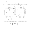
- FIG. 1 shows an example of a refrigerant circuit included in the refrigerating apparatus according to the first embodiment of the present disclosure.
- the refrigerant circuit 1 is provided in, for example, a refrigerating device such as an ultra-low temperature freezer in which the internal temperature of the storage is ⁇ 80 ° C. or lower.
- the refrigerant circuit 1 is a dual refrigerant circuit having a high temperature side refrigerant circuit 10 and a low temperature side refrigerant circuit 20 in which refrigerants circulate independently of each other.
- the high temperature side refrigerant circuit 10 includes a high temperature side compressor 11, a high temperature side condenser 12, a high temperature side decompressor 13, a high temperature side evaporator 14, a dryer 15, and a liquid receiver 16.
- the high temperature side evaporator 14 is an outer tube of the cascade heat exchanger 30 described later, and surrounds the second heat exchanger 23 described later.
- Each of the above devices is connected by a predetermined pipe (high temperature side pipe) so that the refrigerant discharged from the high temperature side compressor 11 (high temperature side refrigerant) returns to the high temperature side compressor 11 again.
- the high temperature side refrigerant circulates in the direction of the arrow in FIG. That is, in the high temperature side refrigerant circuit 10, the high temperature side refrigerant flows through the high temperature side compressor 11, the high temperature side condenser 12, the dryer 15, the high temperature side decompressor 13, the high temperature side evaporator 14, and the liquid receiver 16 in this order. , Return to the high temperature side compressor 11.
- the temperature can be lowered to about ⁇ 40 ° C. in the high temperature side evaporator 14.
- the low temperature side refrigerant circuit 20 includes a low temperature side compressor 21, a first heat exchanger 22, a second heat exchanger 23, a low temperature side decompressor 24, a low temperature side evaporator 25, and a large surface area portion 26. Be prepared.
- each of the above devices is connected by a predetermined pipe (low temperature side pipe) so that the refrigerant discharged from the low temperature side compressor 21 (low temperature side refrigerant) returns to the low temperature side compressor 21 again.
- the low temperature side refrigerant circulates in the direction of the arrow in FIG. That is, in the low temperature side refrigerant circuit 20, the low temperature side refrigerant is the low temperature side compressor 21, the first heat exchanger 22, the second heat exchanger 23, the large surface area portion 26, the low temperature side decompressor 24, and the low temperature side evaporator 25. In this order, and returns to the low temperature side compressor 21.
- an ultralow temperature of ⁇ 80 ° C. or lower can be obtained in the low temperature side evaporator 25.
- the first heat exchanger 22 cools the refrigerant passing through the inside in the gas phase.
- the first heat exchanger 22 may be a condenser that condenses the refrigerant passing through the inside thereof.
- the second heat exchanger 23 is the inner tube of the cascade heat exchanger 30. That is, the second heat exchanger 23, which is an inner pipe, is surrounded by the high temperature side evaporator 14 which is an outer pipe. In the cascade heat exchanger 30, the low-temperature refrigerant passing through the high-temperature side evaporator 14 and the high-temperature refrigerant passing through the second heat exchanger 23 exchange heat. At this time, the high-temperature refrigerant passing through the second heat exchanger 23 condenses. When the first heat exchanger 22 is a condenser, the second heat exchanger 23 cools the liquid phase refrigerant passing through the inside thereof.
- the unit 26 is arranged.
- the large surface area portion 26 is a portion having a larger surface area per unit length in the direction in which the refrigerant flows than any of the low temperature side pipes, particularly the upstream side pipes 26a and the downstream side pipes 26b.
- the large surface area portion 26 is, for example, a large-diameter pipe or a container-shaped member.
- the large-diameter pipe is a pipe having a larger volume per unit length in the direction in which the refrigerant flows than at least the upstream side pipe 26a and the downstream side pipe 26b.
- the container-shaped member is, for example, a dehydrator that adsorbs water in the low-temperature side refrigerant circuit 20.
- the large surface area portion 26 may have an inner diameter of the same size as the inner diameters of the upstream side pipe 26a and the downstream side pipe 26b, and may be thicker than the upstream side pipe 26a and the downstream side pipe 26b. In the following description, the large surface area portion 26 will be described as a container-shaped member.
- the upstream side pipe 26a is connected to the large surface area portion 26 from the upstream side.
- the upstream side pipe 26a may connect the second heat exchanger 23 and the large surface area portion 26.
- a downstream pipe 26b is connected to the large surface area portion 26 from the downstream side.
- the downstream side pipe 26b may connect the large surface area portion 26 and the low temperature side decompressor 24.
- the refrigerant flowing into the large surface area portion 26 is a liquid.
- the liquid refrigerant (low temperature side refrigerant) that flows into the large surface area portion 26 from the upstream side of the large surface area portion 26 and flows out to the downstream side of the large surface area portion 26 is temporarily stored. In other words, it flows inside the large surface area portion 26 at a relatively low speed.
- a temperature sensor T1 for detecting the temperature of the refrigerant passing through the large surface area portion 26 is installed on the surface of the large surface area portion 26.
- the high temperature side refrigerant circuit 10 and the low temperature side refrigerant circuit 20 may each have auxiliary equipment (not shown).
- auxiliary equipment not shown.
- a temperature sensor T1 is installed on the surface of those auxiliary machines. May be good.
- the detected value of the temperature sensor T1 is input to the control unit 40 provided in the refrigerating device.
- the control unit 40 adjusts the high temperature side compressor 11 or the inverter that adjusts the rotation speed thereof, and the low temperature side compressor 21 or its rotation speed based on the set temperature of the storage and the detection value of the temperature sensor T1. Control at least one of the inverters.
- the refrigerating device also includes a temperature sensor other than the temperature sensor T1, for example, a temperature sensor that detects the temperature inside the storage, and the control unit 40 is based on the detection values of a plurality of temperature sensors including the temperature sensor T1.
- the controlled device may be controlled.
- the object to be cooled arranged in the storage is the refrigerant flowing in the low temperature side evaporator 25, that is, the refrigerant circulating in the low temperature side refrigerant circuit 20 (low temperature side refrigerant). ) Is cooled. Further, the temperature sensor T1 is installed on the low temperature side refrigerant circuit 20 side.
- the temperature sensor T1 can detect the temperature of the low temperature side refrigerant that directly acts on the cooling of the cooling object, not the temperature of the high temperature side refrigerant that indirectly acts on the cooling of the cooling object. Therefore, more efficient operation of the refrigerant circuit 1 can be realized by controlling the controlled device such as the high temperature side compressor 11 or the low temperature side compressor 21 by using the detected value of the temperature sensor T1.
- the temperature sensor T1 is not in the gas phase or the gas-liquid mixed state, but is at the position where the refrigerant which is the liquid phase flows, specifically, the downstream side of the second heat exchanger 23 and the upstream side of the low temperature side decompressor 24. It is installed in the piping section located on the side. Liquids have higher thermal conductivity than gases. Therefore, when the temperature of the flowing refrigerant changes, the temperature change of the refrigerant can be detected more quickly in the portion where the liquid phase refrigerant flows than in the portion where the gas phase refrigerant flows. That is, according to the present embodiment, the temperature change of the refrigerant flowing through the low temperature side refrigerant circuit can be detected more quickly, and by extension, more efficient operation of the refrigerant circuit 1 can be realized.
- the low temperature side evaporator 25 is a portion in the refrigerant circuit 1 in which the refrigerant in the lowest temperature state flows, is arranged so as to surround the storage in which the object to be cooled is arranged, and is contained in the heat insulating material. It is in an enclosed state. Therefore, if the temperature sensor T1 is installed in the low temperature side evaporator 25 or the piping near the upstream side or the downstream side thereof, the temperature sensor T1 is also enclosed in the heat insulating material, and it is necessary to remove the heat insulating material when performing maintenance. Occurs. That is, it becomes difficult to maintain the temperature sensor T1.
- the temperature sensor T1 is arranged between the second heat exchanger 23 and the low temperature side decompressor 24, that is, a portion that does not necessarily have to be sealed in the heat insulating material. Therefore, according to this embodiment, maintenance of the temperature sensor T1 or its mounting structure can be easily performed.
- the temperature of the refrigerant flowing in the large surface area portion 26 is also sufficiently lower than the outside air. Therefore, there is a possibility that condensed water or ice adheres to the large surface area portion 26, that is, around the temperature sensor T1. If dew condensation water adheres around the temperature sensor T1, the detection temperature may become inaccurate. Further, if ice adheres, the temperature sensor T1 may be damaged.
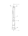
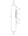
- FIG. 2 is a front view of the temperature sensor mounting pipe 101 according to the first embodiment.
- FIG. 3 is a cross-sectional view taken along the line AA of FIG. 2, that is, a vertical cross-sectional view of the temperature sensor mounting tube 101.
- the temperature sensor mounting pipe 101 is formed by processing a metal pipe, for example, a copper pipe. One end of the temperature sensor mounting pipe 101 is open, forming an open end 102. 2 and 3 show a temperature sensor mounting tube 101 in a state where the opening end 102 is arranged so as to be located on the upper side.
- the description will be made on the assumption that the opening end 102 is located on the upper side, but it goes without saying that the opening end 102 does not have to be located on the upper side.
- the other end of the temperature sensor mounting tube 101 is sealed, forming a sealed end 103.
- the sealing end 103 is formed by crimping the other end of the temperature sensor mounting pipe 101 so that two flat plates are overlapped with each other, and then welding the opposing flat plate-shaped portions to each other. It is formed by sealing the gap between the two with the welded portion 103a.
- the weld 103a extends from the left end to the right end of the flat plate portion for complete sealing.
- the narrowed portion 104 is formed by crimping a portion between the open end portion 102 and the sealing end portion 103. In the example shown in FIG. 2, a gap is left inside the narrowed portion 104, but the narrowed portion 104 may be formed by being crimped so as not to leave a gap.
- a first intermediate portion 105 is formed between the opening end portion 102 and the narrowed portion 104.
- the first intermediate portion 105 is a hollow pipe-shaped portion having one end narrowed.
- a second intermediate portion 106 is formed between the sealing end portion 103 and the narrowed portion 104.
- the second intermediate portion 106 is a hollow pipe-shaped portion having both ends narrowed.
- the distance between the sealing end portion 103 and the narrowed portion 104, that is, the length of the second intermediate portion 106 is larger than the length of the welded portion 103a.
- FIG. 3 shows the temperature sensor T1 inserted into the temperature sensor mounting tube 101 from the opening end.
- the temperature sensor T1 is placed on the narrowed portion 104.
- the temperature sensor T1 may be sandwiched by the narrowed portion 104. According to the temperature sensor mounting tube 101, the temperature sensor T1 can be positioned at a predetermined position regardless of whether it is placed on the narrowed portion 104 or sandwiched by the narrowed portion 104.
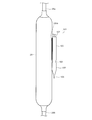
- FIG. 4 is a diagram showing a temperature sensor mounting structure according to the first embodiment of the present disclosure.
- the temperature sensor mounting tube 101 is attached to the large surface area portion 26 made of metal by welding.
- the first intermediate portion 105 is welded to the large surface area portion 26 so that the welded portion 105a is formed.
- the temperature sensor mounting tube 101 is mounted so that the temperature sensor T1 arranged inside the temperature sensor mounting tube 101, that is, the narrowed portion 104 is located at the center of the large surface area portion 26 in the front view. By mounting at such a position, the surface temperature of the large surface area portion 26 can be uniformly sensed, and the temperature of the liquid inside the large surface area portion 26 can be measured more accurately.
- the first intermediate portion 105 is longer than the other portions constituting the temperature sensor mounting pipe 101. Therefore, a sufficient length of the welded portion 105a can be secured, and the temperature sensor mounting pipe 101 can be reliably attached to the large surface area portion 26.
- the length and position of the welded portion 105a are not particularly limited as long as the temperature sensor mounting pipe 101 is securely attached to the large surface area portion 26.
- the temperature sensor mounting pipe 101 When the temperature sensor mounting pipe 101 is attached to the large surface area portion 26 by welding, heat is generated and transmitted to the temperature sensor mounting pipe 101. However, a sufficient distance is secured between the sealing end portion 103 and the narrowed portion 104. Specifically, as described above, the distance between the sealing end portion 103 and the narrowed portion 104 is larger than the length of the welded portion 103a. Therefore, of the heat generated when the temperature sensor mounting tube 101 is attached to the large surface area portion 26 by welding, the amount of heat transferred to the sealing end portion 103 is sufficiently small, and the temperature rise at the sealing end portion 103 is small. Therefore, when the temperature sensor mounting tube 101 is attached to the large surface area portion 26 by welding, it is possible to prevent the welded portion 103a at the sealing end portion 103 from melting and insufficient sealing of the sealing end portion 103. Can be done.
- the temperature sensor T1 After being attached by welding, the temperature sensor T1 is inserted into the temperature sensor attachment tube 101 via the open end 102. As described above, since the temperature sensor T1 is placed on the narrowed portion 104, the temperature sensor T1 can be positioned at a predetermined position.
- the temperature sensor T1 may be sandwiched by the narrowed portion 104.
- the temperature sensor T1 is sandwiched by the narrowed portion 104, even if the large surface area portion 26 vibrates under the influence of, for example, the high temperature side compressor 11 or the low temperature side compressor 21, the temperature sensor mounting tube 101
- the temperature sensor T1 does not run wild inside, and can always maintain a state of being in contact with the large surface area portion 26 via the temperature sensor mounting tube 101. That is, the temperature of the refrigerant can be measured more accurately.
- the temperature sensor T1 can be positioned at a predetermined position as in the case where the temperature sensor T1 is placed on the narrowed portion 104.
- the opening of the opening end 102 is sealed with, for example, a paste-like sealing material (not shown).
- a paste-like sealing material not shown.
- the temperature sensor mounting tube 101 is completely shut off from the outside air. Therefore, for example, even when the large surface area portion 26 becomes low temperature or extremely low temperature, water droplets generated by dew condensation of moisture in the surrounding atmosphere adhere to the temperature sensor T1, and the temperature measurement becomes inaccurate. , It is possible to prevent ice from adhering and damaging the temperature sensor T1.
- the sealing end portion 103 may be sealed by the welded portion 103a before the temperature sensor mounting pipe 101 is attached to the large surface area portion 26, or is attached to the large surface area portion 26 via the welded portion 105a. Later, it may be sealed by the weld 103a. In either case, the sealing end 103 can be sealed by simply welding, so that the lower end of the temperature sensor mounting tube 101 is compared with the case of sealing using, for example, a paste-like sealing material. The part can be easily sealed. When the sealing end 103 is sealed after the temperature sensor mounting tube 101 is attached to the large surface area 26, the working posture tends to be unstable when the sealing end 103 is sealed using a paste-like sealing material. Therefore, the advantage is particularly large.
- the temperature sensor mounting tube is attached to the large surface area portion 26.
- the sealing end portion 103 can be easily sealed. That is, if it is sealed without using a sealing material, it does not necessarily have to be sealed by the welded portion 103a.
- the sealing end portion 103 may be sealed by mechanical coupling such as caulking or pressure contacting the opposing flat plate-shaped portions of the sealing end portion 103 with each other.
- the sealing end 103 may be sealed by material bonding such as brazing welding, ultrasonic welding, and welding.
- the sealing end 103 may be sealed by a chemical bond such as adhesion.
- the sealing end 103 By sealing the sealing end 103 by combining any two or more of mechanical bonding, material bonding, and chemical bonding, the sealing becomes more reliable, and the temperature sensor T1 in the temperature sensor mounting tube 101 can be sealed. It can be more reliably blocked from the outside air.
- Patent Document 2 Japanese Unexamined Patent Publication No. 08-0823308
- the fixing device disclosed in Patent Document 2 requires a caulking operation after inserting the temperature sensor into the fixing device. Therefore, there is a problem that the installation work is troublesome. Further, in the fixing device disclosed in Patent Document 2, the temperature sensor is exposed to the outside air. Therefore, when the temperature is measured by the temperature sensor at a low temperature, moisture in the outside air may condense and the temperature measurement may become inaccurate. Further, when the part where the temperature is measured by the temperature sensor is extremely low temperature, the moisture in the outside air may solidify and damage the temperature sensor.
- An object of the present invention is to provide a sensor mounting structure.
- the temperature sensor mounting tube according to the present disclosure is made of metal and is arranged between an opening end portion having an opening into which the temperature sensor is inserted, a sealing end portion, and the opening end portion and the sealing end portion. It is provided with a narrowed portion.
- the temperature sensor mounting structure includes the temperature sensor mounting pipe and a metal attachment to which the temperature sensor mounting pipe is mounted, and is located between the open end portion and the narrowed portion. The portion is attached to the object to be attached by welding.
- the temperature sensor can be easily mounted and the temperature can be measured accurately without damaging the temperature sensor.
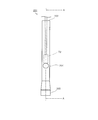
- FIG. 5 is a front view of the temperature sensor mounting tube 201 according to the second embodiment of the present disclosure
- FIG. 6 is a cross-sectional view taken along the line AA of FIG. 5, that is, the temperature sensor mounting tube 201 according to the present disclosure. It is a vertical sectional view of.
- the temperature sensor mounting pipe 201 is formed by processing a pipe made of metal, for example, copper.
- One end of the temperature sensor mounting pipe 201 is open, and constitutes the open end portion 202.
- 5 and 6 show a temperature sensor mounting tube 201 in a state where the opening end 202 is arranged so as to be located on the upper side.
- the description will be made on the assumption that the opening end portion 202 is located on the upper side, but it goes without saying that the opening end portion 202 does not have to be located on the upper side.
- the other end of the temperature sensor mounting tube 201 is sealed and constitutes the sealed end portion 203.
- the sealing end portion 203 is formed by crimping the other end of the temperature sensor mounting pipe 201 so that two flat plates are overlapped with each other, and then welding the opposing flat plate-shaped portions to each other. It is formed by sealing the gap between the two with the welded portion 203a.
- the welded portion 203a extends from the left end to the right end of the flat plate portion for complete sealing.
- the narrowed portion 204 is formed by crimping a portion between the open end portion 202 and the sealing end portion 203. In the example shown in FIG. 5, a gap is left inside the narrowed portion 204, but the narrowed portion 204 may be formed by being crimped so as not to leave a gap.
- a first intermediate portion 205 is formed between the opening end portion 202 and the narrowed portion 204.
- the first intermediate portion 205 is a hollow pipe-shaped portion having one end narrowed.
- a second intermediate portion 206 is formed between the sealing end portion 203 and the narrowed portion 204.
- the second intermediate portion 206 is a hollow pipe-shaped portion having both ends narrowed.
- the distance between the sealing end portion 203 and the narrowed portion 204, that is, the length of the second intermediate portion 206 is larger than the length of the welded portion 203a.
- FIG. 6 shows the temperature sensor T2 inserted into the temperature sensor mounting tube 201 from the opening end.
- the temperature sensor T2 is placed on the narrowed portion 204.
- FIG. 7 is a diagram showing a temperature sensor mounting structure according to the second embodiment of the present disclosure.
- the temperature sensor mounting tube 201 is attached to a large surface area portion 207 made of metal by welding. Specifically, the first intermediate portion 205 is welded to the large surface area portion 207 so that the welded portion 205a is formed.
- the large surface area portion 207 has a larger surface area per unit length in the direction in which the refrigerant flows than both the pipe connected to the large surface area portion 207 from the upstream side and the pipe connected to the large surface area portion 207 from the downstream side. ..
- the large surface area portion 207 is, for example, a large-diameter pipe or a container-shaped member.
- the large-diameter pipe is a pipe having a larger volume per unit length in the direction in which the refrigerant flows than the pipe connected to at least the large surface area portion 207.
- the container-shaped member is, for example, a dehydrator that adsorbs water in the low-temperature side refrigerant circuit 220.
- the large surface area portion 207 has an inner diameter of the same size as the inner diameter of the pipe connected to the large surface area portion 207, and may be a pipe thicker than the pipe. In the following description, the large surface area portion 207 will be described as a container-shaped member.
- the temperature sensor mounting tube 201 is mounted so that the temperature sensor T2 arranged inside the temperature sensor mounting tube 201, that is, the narrowed portion 204 is located at the center of the large surface area portion 207 in the front view. By mounting at such a position, the surface temperature of the large surface area portion 207 can be uniformly sensed, and the temperature of the liquid inside the large surface area portion 207 can be measured more accurately.
- the first intermediate portion 205 is longer than the other portions constituting the temperature sensor mounting pipe 201. Therefore, a sufficient length of the welded portion 205a can be secured, and the temperature sensor mounting pipe 201 can be reliably mounted on the large surface area portion 207.
- the length and position of the welded portion 205a are not particularly limited as long as the temperature sensor mounting pipe 201 is securely attached to the large surface area portion 207.
- the temperature sensor mounting pipe 201 When the temperature sensor mounting pipe 201 is attached to the large surface area portion 207 by welding, heat is generated and transmitted to the temperature sensor mounting pipe 201. However, a sufficient distance is secured between the sealing end portion 203 and the narrowed portion 204. Specifically, as described above, the distance between the sealing end portion 203 and the narrowed portion 204 is larger than the length of the welded portion 203a. Therefore, of the heat generated when the temperature sensor mounting tube 201 is attached to the large surface area portion 207 by welding, the amount of heat transferred to the sealing end portion 203 is sufficiently small, and the temperature rise at the sealing end portion 203 is small. Therefore, when the temperature sensor mounting pipe 201 is attached to the large surface area portion 207 by welding, it is possible to prevent the welded portion 203a at the sealing end portion 203 from melting and insufficient sealing of the sealing end portion 203. Can be done.
- the temperature sensor T2 After being attached by welding, the temperature sensor T2 is inserted into the temperature sensor mounting tube 201 via the open end 202. As described above, since the temperature sensor T2 is placed on the narrowed portion 204, the temperature sensor T2 can be positioned at a predetermined position.
- the temperature sensor T2 may be sandwiched by the narrowed portion 204.
- the temperature sensor T2 does not run wild inside the temperature sensor mounting tube 201 even if the attached object such as the large surface area portion 207 is a vibrating member, and is always The state of contact with the object to be attached can be maintained via the temperature sensor attachment tube 201. That is, the temperature of the object to be measured can be measured more accurately.
- the temperature sensor T2 can be positioned at a predetermined position as in the case where the temperature sensor T2 is placed on the narrowed portion 204.
- the opening of the opening end 202 is sealed with, for example, a paste-like sealing material (not shown).
- a paste-like sealing material not shown.
- the temperature sensor mounting tube 201 is completely shut off from the outside air. Therefore, even when the object to be attached such as the large surface area portion 207 becomes low temperature or extremely low temperature, water droplets generated by dew condensation of moisture in the surrounding atmosphere adhere to the temperature sensor T2, and the temperature measurement is inaccurate. It is possible to prevent the temperature sensor T2 from being damaged due to the adhesion of ice.
- the sealing end portion 203 may be sealed by the welded portion 203a before the temperature sensor mounting pipe 201 is attached to the large surface area portion 207, or is attached to the large surface area portion 207 via the welded portion 205a. Later, it may be sealed by the welded portion 203a.
- the sealing end portion 203 can be sealed by simply welding, the lower end of the temperature sensor mounting tube 201 is compared with the case of sealing using, for example, a paste-like sealing material. The part can be easily sealed.
- the sealing end portion 203 after attaching the temperature sensor mounting tube 201 to the large surface area portion 207 the working posture tends to be unstable when sealing using a paste-like sealing material. Therefore, the advantage is particularly large.
- the temperature sensor mounting tube is attached to the large surface area portion 207.
- the sealing end portion 203 can be sealed by an easy operation. That is, if it is sealed without using a sealing material, it does not necessarily have to be sealed by the welded portion 203a.
- the sealing end portion 203 may be sealed by mechanical coupling such as caulking or pressure contacting the opposing flat plate-shaped portions of the sealing end portion 203 with each other.
- the sealing end 203 may be sealed by material bonding such as brazing welding, ultrasonic welding, and welding.
- the sealing end portion 203 may be sealed by a chemical bond such as adhesion.
- the sealing end portion 203 By sealing the sealing end portion 203 by combining any two or more of mechanical bonding, material bonding, and chemical bonding, the sealing becomes more reliable, and the temperature sensor T2 in the temperature sensor mounting tube 201 can be sealed. It can be more reliably blocked from the outside air.
- FIG. 8 shows an example of a refrigerant circuit included in the refrigerating apparatus according to the second embodiment of the present disclosure.
- the refrigerant circuit 200 is provided in, for example, a refrigerating device such as an ultra-low temperature freezer in which the internal temperature of the storage is ⁇ 80 ° C. or lower.
- the refrigerant circuit 200 is a dual refrigerant circuit having a high temperature side refrigerant circuit 210 and a low temperature side refrigerant circuit 220 in which refrigerants circulate independently of each other.
- the high temperature side refrigerant circuit 210 includes a high temperature side compressor 211, a high temperature side condenser 212, a high temperature side decompressor 213, a high temperature side evaporator 214, a dryer 215, and a liquid receiver 216.
- the high temperature side evaporator 214 is an outer tube of the cascade capacitor 230, which will be described later.
- Each of the above devices is connected by a predetermined pipe (high temperature side pipe) so that the refrigerant discharged from the high temperature side compressor 211 returns to the high temperature side compressor 211 again.
- the high temperature side refrigerant circulates in the direction of the arrow in FIG. That is, in the high temperature side refrigerant circuit 210, the high temperature side refrigerant flows through the high temperature side compressor 211, the high temperature side condenser 212, the dryer 215, the high temperature side decompressor 213, the high temperature side evaporator 214, and the liquid receiver 216 in this order. , Return to the high temperature side compressor 211.
- the temperature can be lowered to about ⁇ 40 ° C. in the high temperature side evaporator 214.
- the low temperature side refrigerant circuit 220 includes a low temperature side compressor 221, a first heat exchanger 222, a second heat exchanger 223, a low temperature side decompressor 224, a low temperature side evaporator 225, and a large surface area portion 207. Be prepared.
- each of the above devices is connected by a predetermined pipe (low temperature side pipe) so that the refrigerant discharged from the low temperature side compressor 221 returns to the low temperature side compressor 221 again.
- the low temperature side refrigerant circulates in the direction of the arrow in FIG. That is, in the low temperature side refrigerant circuit 220, the low temperature side refrigerant is the low temperature side compressor 221, the first heat exchanger 222, the second heat exchanger 223, the large surface area portion 207, the low temperature side decompressor 224, and the low temperature side evaporator 225. Flows in this order and returns to the low temperature compressor 221.
- an ultralow temperature of ⁇ 80 ° C. or lower can be obtained in the low temperature side evaporator 225.
- the first heat exchanger 222 cools the refrigerant passing through the inside in the gas phase.
- the first heat exchanger 222 may be a condenser that condenses the refrigerant passing through the inside thereof.
- the second heat exchanger 223 is the inner tube of the cascade capacitor 230. That is, the second heat exchanger 223, which is an inner pipe, is surrounded by the high temperature side evaporator 214, which is an outer pipe. In the cascade condenser 230, the low-temperature refrigerant passing through the high-temperature side evaporator 214 and the high-temperature refrigerant passing through the second heat exchanger 223 exchange heat. At this time, the high-temperature refrigerant passing through the second heat exchanger 223 condenses. When the first heat exchanger 222 is a condenser, the second heat exchanger 223 cools the liquid phase refrigerant passing through the inside thereof.
- a large surface area portion 207 is arranged on the downstream side of the second heat exchanger 223 and on the upstream side of the low temperature side decompressor 224.
- the large surface area portion 207 may be covered with a heat insulating material composed of a foaming agent.
- the temperature sensor mounting tube 201 is also covered with the heat insulating material.
- the foaming agent does not enter the temperature sensor mounting tube 201. Therefore, since the foaming agent does not intervene between the temperature sensor T2 and the large surface area portion 207, the temperature of the object to be measured can be measured more accurately.
- the refrigerant flowing into the large surface area portion 207 is a liquid.
- the liquid refrigerant that flows into the large surface area portion 207 from the upstream side of the large surface area portion 207 and flows out to the downstream side of the large surface area portion 207 is temporarily stored. In other words, it flows inside the large surface area portion 207 at a relatively low speed. Then, the temperature of the refrigerant passing through the large surface area portion 207 can be quickly transmitted to the temperature sensor T2 via the large surface area portion 207, the welded portion 205a, and the temperature sensor mounting pipe 201.
- the high temperature side refrigerant circuit 210 and the low temperature side refrigerant circuit 220 may each have auxiliary equipment (not shown). Further, those auxiliary machines may be mounted portions to which the temperature sensor mounting pipe 201 is mounted.
- the refrigerating device provided with the refrigerant circuit 200 includes a control unit 240.
- the control unit 240 controls the rotation speeds of the high temperature side compressor 211 and the low temperature side compressor 221 based on the set temperature of the storage and the temperature detected by the temperature sensor T2. According to the temperature sensor mounting structure including the temperature sensor mounting tube 201 and the temperature sensor mounting tube 201, the temperature of the refrigerant in the large surface area portion 207 can be measured more accurately. Therefore, the rotation speed of the high temperature side compressor 211 and the low temperature side compressor 221 can be controlled more appropriately.
- the refrigerating apparatus according to the present disclosure is suitable for a refrigerating apparatus provided with a dual refrigerant circuit such as a cryogenic freezer. Therefore, its industrial applicability is enormous. Further, the temperature sensor mounting tube and the temperature sensor mounting structure according to the present disclosure can be used for measuring the temperature of a member made of metal such as a refrigerating device provided with a refrigerant circuit or an object existing inside the member. Therefore, its industrial applicability is enormous.
Abstract
冷凍装置は、高温側冷媒が循環する高温側冷媒回路と、低温側冷媒が循環する低温側冷媒回路と、前記高温側冷媒によって前記低温側冷媒を冷却するカスケード熱交換器と、を備え、前記低温側冷媒回路には、前記カスケード熱交換器の下流側に低温側減圧器が配置されているとともに、前記カスケード熱交換器と前記低温側減圧器との間の配管部に、温度センサが設置されている。
Description
本開示は、冷凍装置、特に、二元冷媒回路を備える冷凍装置、並びに、温度センサ取付管及び温度センサ取付構造に関する。
例えば特許文献1に開示されるように、従来、高温側冷媒回路と低温側冷媒回路とを備え、高温側冷媒回路中の冷媒によって低温側冷媒回路中の冷媒を冷却する二元冷媒回路を備える冷凍装置が用いられている。
一般的に、冷凍装置は、冷却対象物が配置される収納庫の温度が目標温度になるように、圧縮機等の被制御機器の制御が行われる。
冷凍装置が二元冷媒回路を備える場合、冷媒回路が2系統あり、構成が複雑である。そのため、単に収納庫内の温度を検出し、その温度が目標温度になるように被制御機器を制御するだけでは、必ずしも効率が良い運転にならない可能性がある。
本開示は、冷凍装置をより効率的に作動させることを目的とする。
本開示に係る冷凍装置は、高温側冷媒が循環する高温側冷媒回路と、低温側冷媒が循環する低温側冷媒回路と、前記高温側冷媒によって前記低温側冷媒を冷却するカスケード熱交換器と、を備え、前記低温側冷媒回路には、前記カスケード熱交換器の下流側に低温側減圧器が配置されているとともに、前記カスケード熱交換器と前記低温側減圧器との間の配管部に、温度センサが設置されている。
本開示によれば、冷凍装置をより効率的に作動させることができる。
以下、本開示の実施形態について、図面を参照しつつ詳細に説明する。なお、以下に説明する実施形態は一例であり、本開示はこの実施形態により限定されるものではない。
(第1実施形態)
図1は、本開示の第1実施形態に係る冷凍装置が備える冷媒回路の一例を示している。冷媒回路1は、例えば、収納庫の内部温度が-80℃以下となる超低温フリーザのような冷凍装置に備え付けられている。
図1は、本開示の第1実施形態に係る冷凍装置が備える冷媒回路の一例を示している。冷媒回路1は、例えば、収納庫の内部温度が-80℃以下となる超低温フリーザのような冷凍装置に備え付けられている。
冷媒回路1は、互いに独立して冷媒が循環する高温側冷媒回路10及び低温側冷媒回路20を有する二元冷媒回路である。
高温側冷媒回路10は、高温側圧縮機11と、高温側凝縮器12と、高温側減圧器13と、高温側蒸発器14と、乾燥器15と、受液器16とを備える。
高温側蒸発器14は、後に説明するカスケード熱交換器30の外管であり、後述する第2熱交換器23を取り囲んでいる。
高温側圧縮機11から吐出された冷媒(高温側冷媒)が再び高温側圧縮機11に戻るように上記各機器が所定の配管(高温側配管)で接続されている。高温側冷媒は、図1中の矢印の方向に循環する。すなわち、高温側冷媒回路10では、高温側冷媒が、高温側圧縮機11、高温側凝縮器12、乾燥器15、高温側減圧器13、高温側蒸発器14、受液器16をこの順に流れ、高温側圧縮機11に帰還する。なお、高温側冷媒回路10における冷凍サイクルによって、高温側蒸発器14において-40℃程度まで温度を下げることができる。
低温側冷媒回路20は、低温側圧縮機21と、第1熱交換器22と、第2熱交換器23と、低温側減圧器24と、低温側蒸発器25と、大表面積部26とを備える。
低温側圧縮機21から吐出された冷媒(低温側冷媒)が再び低温側圧縮機21に戻るように上記各機器が所定の配管(低温側配管)で接続されている。低温側冷媒は、図1中の矢印の方向に循環する。すなわち、低温側冷媒回路20では、低温側冷媒が、低温側圧縮機21、第1熱交換器22、第2熱交換器23、大表面積部26、低温側減圧器24、低温側蒸発器25をこの順に流れ、低温側圧縮機21に帰還する。なお、低温側冷媒回路20における冷凍サイクルによって、低温側蒸発器25において-80℃以下の超低温が得られる。
第1熱交換器22は、その内部を通過する冷媒を気相のまま冷却する。なお、第1熱交換器22は、その内部を通過する冷媒を凝縮させる凝縮器であってもよい。
第2熱交換器23は、カスケード熱交換器30の内管である。すなわち、内管である第2熱交換器23が、外管である高温側蒸発器14に囲まれている。カスケード熱交換器30内では、高温側蒸発器14内を通過する低温の冷媒と、第2熱交換器23内を通過する高温の冷媒とが熱交換する。このとき、第2熱交換器23内を通過する高温の冷媒は、凝縮する。なお、第1熱交換器22が凝縮器である場合、第2熱交換器23は、その内部を通過する液相の冷媒を冷却する。
また、第2熱交換器23の下流側に位置する上流側配管26aと、低温側減圧器24の上流側に位置する下流側配管26bとの間には、内部を低温側冷媒が流れる大表面積部26が配置されている。大表面積部26は、低温側配管、特に、上流側配管26a及び下流側配管26bのいずれよりも、冷媒が流れる方向の単位長さ当たりの表面積が大きい部位である。大表面積部26は、例えば、大径の配管や容器状部材である。大径の配管とは少なくとも上流側配管26aおよび下流側配管26bよりも冷媒が流れる方向の単位長さあたりの容積が大きい配管である。また、容器状部材は例えば、低温側冷媒回路20中の水分を吸着するデハイドレータである。また、大表面積部26は、上流側配管26a及び下流側配管26bの内径と同じ大きさの内径を有し、上流側配管26a及び下流側配管26bよりも肉厚の配管であってもよい。以下の説明では、大表面積部26は、容器状部材であるとして説明する。
大表面積部26には、上流側から上流側配管26aが接続されている。上流側配管26aは、第2熱交換器23と大表面積部26を接続してもよい。
大表面積部26には、下流側から下流側配管26bが接続されている。下流側配管26bは、大表面積部26と低温側減圧器24を接続してもよい。
また、大表面積部26に流入する冷媒は液体となっている。
よって、大表面積部26には、大表面積部26の上流側から流入し、大表面積部26の下流側に流出する液体状の冷媒(低温側冷媒)が、一時的に貯留される。言い換えると、大表面積部26の内部を比較的低速で流れる。大表面積部26の表面には、その内部を通過する冷媒の温度を検出する温度センサT1が設置されている。
高温側冷媒回路10及び低温側冷媒回路20は、それぞれ、図示されていない補機を有していても良い。それらの補機が、低温側冷媒回路20において、第2熱交換器23と低温側減圧器24との間に配置されている場合は、それらの補機の表面に温度センサT1を設置してもよい。
温度センサT1の検出値は、冷凍装置が備える制御部40に入力される。制御部40は、収納庫の設定温度及び温度センサT1の検出値等に基づいて、高温側圧縮機11又はその回転数を調整するインバータ、及び、低温側圧縮機21又はその回転数を調整するインバータの少なくとも一方を制御する。なお、冷凍装置は、温度センサT1以外の温度センサ、例えば、収納庫内の温度を検出する温度センサも備え、制御部40は、温度センサT1を含む複数個の温度センサの検出値に基づいて被制御機器を制御してもよいことは勿論である。
以上のように構成された冷媒回路1において、収納庫内に配置された冷却対象物は、低温側蒸発器25内を流れる冷媒、つまり、低温側冷媒回路20内を循環する冷媒(低温側冷媒)によって冷却される。また、温度センサT1は、低温側冷媒回路20側に設置されている。
つまり、温度センサT1は、冷却対象物の冷却に間接的に作用する高温側冷媒の温度ではなく、冷却対象物の冷却に直接的に作用する低温側冷媒の温度を検出することができる。よって、温度センサT1の検出値を用いて高温側圧縮機11又は低温側圧縮機21等の被制御機器を制御することによって、より効率的な冷媒回路1の運転を実現することができる。
しかも、温度センサT1は、気相または気液混合状態ではなく、液相である冷媒が流れる位置、具体的には、第2熱交換器23の下流側であって低温側減圧器24の上流側に位置する配管部に設置されている。液体は気体よりも熱伝導率が大きい。よって、流通する冷媒の温度が変化した場合、気相の冷媒が流れる部位よりも液相の冷媒が流れる部位の方が、より迅速に冷媒の温度変化を検出することができる。すなわち、本実施形態によれば、低温側冷媒回路を流れる冷媒の温度変化を、より迅速に検出することができ、ひいては、より効率的な冷媒回路1の運転を実現することができる。
また、低温側蒸発器25は、冷媒回路1中で最も温度が低い状態の冷媒が流れる部分であり、冷却対象物が配置される収納庫を取り巻くように配置され、かつ、断熱材の中に封入された状態になっている。よって、低温側蒸発器25又はその上流側若しくは下流側近傍の配管に温度センサT1を設置すると、温度センサT1も断熱材の中に封入されてしまい、メンテナンスを行う場合、断熱材を剥がす必要が生じる。つまり、温度センサT1のメンテナンスを行うことが難しくなる。これに対し、本実施形態では、温度センサT1は、第2熱交換器23と低温側減圧器24との間、つまり、必ずしも断熱材の中に封入する必要のない部位に配置されている。よって、本実施形態によれば、温度センサT1またはその取付構造のメンテナンスを容易に行うことができる。
なお、低温側蒸発器25内を流れる冷媒よりも高いとはいえ、大表面積部26内を流れる冷媒の温度も外気に比べると十分に低い。よって、大表面積部26つまり温度センサT1の周囲に結露水または氷が付着する可能性がある。温度センサT1の周囲に結露水が付着すると、検出温度が不正確になるおそれがある。また、氷が付着すると、温度センサT1が破損するおそれがある。
このような事態が発生することを未然に防止するため、温度センサT1を外気と遮断された状態で収納する温度センサ取付管を用いてもよい。図2は、第1実施形態に係る温度センサ取付管101の正面図である。図3は、図2のA-A断面矢視図、つまり、温度センサ取付管101の縦断面図である。
温度センサ取付管101は、金属例えば銅製のパイプを加工することによって形成されている。温度センサ取付管101の一端は、開口しており、開口端部102を構成している。図2及び図3には、開口端部102が上側に位置するように配置された状態の温度センサ取付管101が示されている。以下、開口端部102が上側に位置しているという前提で説明を行うが、開口端部102が上側に位置していなくてもよいことは言うまでもない。
温度センサ取付管101の他端は、封止されており、封止端部103を構成している。封止端部103は、温度センサ取付管101の他端を加締めて2枚の平板が重なったような状態とした後に、対向する平板状部位同士を溶接して、対向する部位同士の間の隙間を溶接部103aで封止することにより形成されている。完全に封止するために、溶接部103aは、平板状部位の左端から右端まで延在する。
狭窄部104は、開口端部102と封止端部103との間の部位を、加締めることによって形成されている。図2に示される例では、狭窄部104の内部には隙間が残されているが、隙間が残らないように加締められて狭窄部104が形成されていてもよい。
開口端部102と狭窄部104との間には、第1中間部105が形成されている。第1中間部105は、一端が窄まっている中空パイプ状の部分である。
封止端部103と狭窄部104との間には、第2中間部106が形成されている。第2中間部106は、両端が窄まっている中空パイプ状の部分である。封止端部103と狭窄部104との間の距離、つまり、第2中間部106の長さは、溶接部103aの長さよりも大きい。
図3には、温度センサ取付管101に開口端部から挿入された温度センサT1が示されている。温度センサT1は、狭窄部104の上に載置されている。なお、温度センサT1は、狭窄部104によって挟持されていてもよい。温度センサ取付管101によれば、狭窄部104の上に載置された場合も、狭窄部104によって挟持された場合も、温度センサT1を所定の位置に位置決めすることができる。
図4は、本開示の第1実施形態に係る温度センサ取付構造を示す図である。温度センサ取付管101は、金属製の大表面積部26に、溶接によって取り付けられている。具体的には、溶接部105aが形成されるように、第1中間部105が、大表面積部26に溶接されている。
また、温度センサ取付管101は、その内部に配置される温度センサT1、つまり、狭窄部104が、正面視で大表面積部26の中央に位置するように取り付けられる。このような位置に取り付けることにより、大表面積部26の表面温度を均一に感知することができ、大表面積部26内部の液体の温度をより正確に測定することができる。
第1中間部105は、温度センサ取付管101を構成する他の部分よりも長い。よって、溶接部105aの長さを十分に確保することができ、温度センサ取付管101を大表面積部26に確実に取り付けることができる。なお、温度センサ取付管101が大表面積部26に確実に取り付けられさえすれば、溶接部105aの長さ及び位置に特に制限はない。
温度センサ取付管101を大表面積部26に溶接で取り付ける際、熱が発生し、温度センサ取付管101に伝わる。ただし、封止端部103と狭窄部104との間には、十分な距離が確保されている。具体的には、前述のとおり、封止端部103と狭窄部104との間の距離は、溶接部103aの長さよりも大きい。よって、温度センサ取付管101を大表面積部26に溶接で取り付ける際に発生する熱のうち、封止端部103に伝わる熱の量は十分に小さく、封止端部103における温度上昇は小さい。したがって、温度センサ取付管101を大表面積部26に溶接で取り付ける際、封止端部103における溶接部103aが溶けてしまい、封止端部103の封止が不十分になることを防止することができる。
溶接によって取り付けられた後、開口端部102を介して、温度センサT1が温度センサ取付管101の内部に挿入される。前述のとおり、温度センサT1は、狭窄部104の上に載置されているので温度センサT1を所定の位置に位置決めすることができる。
なお、温度センサT1は、前述のとおり、狭窄部104によって挟持されていてもよい。温度センサT1が、狭窄部104によって挟持されている場合、大表面積部26が、例えば高温側圧縮機11または低温側圧縮機21の影響を受けて、振動したとしても、温度センサ取付管101の内部で温度センサT1は暴れず、常に温度センサ取付管101を介して、大表面積部26に接触した状態を維持することができる。つまり、より正確に、冷媒の温度を測定することができる。また、温度センサ取付管101によれば、狭窄部104によって挟持された場合も、狭窄部104の上に載置された場合と同様に、温度センサT1を所定の位置に位置決めすることができる。
温度センサT1が挿入された後、開口端部102の開口は、例えばペースト状の封止材(不図示)によって封止される。これによって、温度センサ取付管101は、完全に外気から遮断される。よって、例えば大表面積部26が低温または極低温になる場合であっても、周辺大気中の水分が結露して発生する水滴が温度センサT1に付着し、温度測定が不正確になること、及び、氷が付着し、温度センサT1が破損することを防止することができる。
なお、封止端部103は、温度センサ取付管101を大表面積部26に取り付ける前に、溶接部103aによって封止されていてもよいし、大表面積部26に溶接部105aを介して取り付けた後に、溶接部103aによって封止されてもよい。何れの場合においても、単に封止端部103を溶接するだけで封止することができるので、例えばペースト状の封止材を用いて封止する場合に比べて、温度センサ取付管101の下端部を容易に封止することができる。大表面積部26に温度センサ取付管101を取り付けた後に封止端部103を封止する場合において、ペースト状の封止材を用いて封止する場合は、作業姿勢が不安定なものとなりがちなので、特に利点が大きい。
なお、封止端部103の封止方法として、封止端部103の対向する平板状部位同士が互いに接触して封止される手法が採用されれば、大表面積部26に温度センサ取付管101を取り付けた後に封止端部103を封止する場合において、封止端部103を容易な作業で封止できる。つまり、封止材を用いずに封止されるのであれば、必ずしも溶接部103aによって封止されなくてもよい。
封止端部103の封止方法としては様々な方法が採用され得る。封止端部103は、かしめや封止端部103の対向する平板状部位同士を圧接するなど、機械的結合により封止されていてもよい。封止端部103は、ろう付け溶接、超音波溶着、及び溶接などの材質的結合によって封止されていてもよい。または、封止端部103は、接着などの化学的結合により、封止されていてもよい。
機械的結合、材質的結合及び化学的結合のいずれか2つ以上を組み合わせて封止端部103を封止することで、封止がより確実となり、温度センサ取付管101内の温度センサT1を外気からより確実に遮断することができる。
(第2実施形態)
ところで、従来、例えば特許文献2(特開平08-082308号公報)に開示される温度センサの固定装置が提案されている。
ところで、従来、例えば特許文献2(特開平08-082308号公報)に開示される温度センサの固定装置が提案されている。
しかしながら、特許文献2に開示される固定装置は、固定装置に温度センサを挿入した後のかしめ作業を要するものである。よって、取付作業が面倒であるという問題点を有している。また、特許文献2に開示される固定装置では、温度センサは外気に触れている。そのため、温度センサによって温度測定する部位が低温である場合、外気中の水分が結露し、温度測定が不正確になるおそれがある。さらに、温度センサによって温度測定する部位が極低温である場合、外気中の水分が凝固し、温度センサを破損させてしまうおそれがある。
本開示は、このような状況に鑑みなされたものであり、温度センサを簡単に取り付けることができ、かつ、温度センサを破損させることなく正確に温度を測定することができる温度センサ取付管及び温度センサ取付構造を提供することを課題とする。
本開示に係る温度センサ取付管は、金属製であり、温度センサが挿入される開口を有する開口端部と、封止端部と、前記開口端部と前記封止端部との間に配置された狭窄部と、を備える。
また、本開示に係る温度センサ取付構造は、前記温度センサ取付管と、前記温度センサ取付管が取り付けられる金属製の被取付物と、を備え、開口端部と狭窄部との間に位置する部分が、溶接によって、前記被取付物に取り付けられている。
本開示に係る温度センサ取付管及び温度センサ取付構造によれば、温度センサを簡単に取り付けることができ、かつ、温度センサを破損させることなく正確に温度を測定することができる。
以下、本開示の第2実施形態について、図面を参照しつつ詳細に説明する。
図5は、本開示の第2実施形態に係る温度センサ取付管201の正面図であり、図6は、図5のA-A断面矢視図、つまり、本開示に係る温度センサ取付管201の縦断面図である。温度センサ取付管201は、金属例えば銅製のパイプを加工することによって形成されている。温度センサ取付管201の一端は、開口しており、開口端部202を構成している。図5及び図6には、開口端部202が上側に位置するように配置された状態の温度センサ取付管201が示されている。以下、開口端部202が上側に位置しているという前提で説明を行うが、開口端部202が上側に位置していなくてもよいことは言うまでもない。
温度センサ取付管201の他端は、封止されており、封止端部203を構成している。封止端部203は、温度センサ取付管201の他端を加締めて2枚の平板が重なったような状態とした後に、対向する平板状部位同士を溶接して、対向する部位同士の間の隙間を溶接部203aで封止することにより形成されている。完全に封止するために、溶接部203aは、平板状部位の左端から右端まで延在する。
狭窄部204は、開口端部202と封止端部203との間の部位を、加締めることによって形成されている。図5に示される例では、狭窄部204の内部には隙間が残されているが、隙間が残らないように加締められて狭窄部204が形成されていてもよい。
開口端部202と狭窄部204との間には、第1中間部205が形成されている。第1中間部205は、一端が窄まっている中空パイプ状の部分である。
封止端部203と狭窄部204との間には、第2中間部206が形成されている。第2中間部206は、両端が窄まっている中空パイプ状の部分である。封止端部203と狭窄部204との間の距離、つまり、第2中間部206の長さは、溶接部203aの長さよりも大きい。
図6には、温度センサ取付管201に開口端部から挿入された温度センサT2が示されている。温度センサT2は、狭窄部204の上に載置されている。
図7は、本開示の第2実施形態に係る温度センサ取付構造を示す図である。温度センサ取付管201は、被取付物であり金属製の大表面積部207に、溶接によって取り付けられている。具体的には、溶接部205aが形成されるように、第1中間部205が、大表面積部207に溶接されている。
ここで、大表面積部207は、大表面積部207に上流側から接続する配管及び大表面積部207に下流側から接続する配管のいずれよりも、冷媒が流れる方向の単位長さ当たりの表面積が大きい。大表面積部207は、例えば、大径の配管や容器状部材である。大径の配管とは少なくとも大表面積部207に接続する配管よりも冷媒が流れる方向の単位長さあたりの容積が大きい配管である。また、容器状部材は、例えば、低温側冷媒回路220中の水分を吸着するデハイドレータである。また、大表面積部207は、大表面積部207に接続する配管の内径と同じ大きさの内径を有し、該配管よりも肉厚の配管であってもよい。以下の説明では、大表面積部207は、容器状部材であるとして説明する。
また、温度センサ取付管201は、その内部に配置される温度センサT2、つまり、狭窄部204が、正面視で大表面積部207の中央に位置するように取り付けられる。このような位置に取り付けることにより、大表面積部207の表面温度を均一に感知することができ、大表面積部207内部の液体の温度をより正確に測定することができる。
第1中間部205は、温度センサ取付管201を構成する他の部分よりも長い。よって、溶接部205aの長さを十分に確保することができ、温度センサ取付管201を大表面積部207に確実に取り付けることができる。なお、温度センサ取付管201が大表面積部207に確実に取り付けられさえすれば、溶接部205aの長さ及び位置に特に制限はない。
温度センサ取付管201を大表面積部207に溶接で取り付ける際、熱が発生し、温度センサ取付管201に伝わる。ただし、封止端部203と狭窄部204との間には、十分な距離が確保されている。具体的には、前述のとおり、封止端部203と狭窄部204との間の距離は、溶接部203aの長さよりも大きい。よって、温度センサ取付管201を大表面積部207に溶接で取り付ける際に発生する熱のうち、封止端部203に伝わる熱の量は十分に小さく、封止端部203における温度上昇は小さい。したがって、温度センサ取付管201を大表面積部207に溶接で取り付ける際、封止端部203における溶接部203aが溶けてしまい、封止端部203の封止が不十分になることを防止することができる。
溶接によって取り付けられた後、開口端部202を介して、温度センサT2が温度センサ取付管201の内部に挿入される。前述のとおり、温度センサT2は、狭窄部204の上に載置されているので、温度センサT2を所定の位置に位置決めすることができる。
なお、温度センサT2は、狭窄部204によって挟持されていてもよい。温度センサT2が、狭窄部204によって挟持されている場合、大表面積部207等の被取付物が振動する部材であったとしても、温度センサ取付管201の内部で温度センサT2は暴れず、常に温度センサ取付管201を介して、被取付物に接触した状態を維持することができる。つまり、より正確に、測定対象物の温度を測定することができる。温度センサ取付管201によれば、狭窄部204によって挟持されている場合も、狭窄部204の上に載置された場合と同様に、温度センサT2を所定の位置に位置決めすることができる。
温度センサT2が挿入された後、開口端部202の開口は、例えばペースト状の封止材(不図示)によって封止される。これによって、温度センサ取付管201は、完全に外気から遮断される。よって、例えば大表面積部207等の被取付物が低温または極低温になる場合であっても、周辺大気中の水分が結露して発生する水滴が温度センサT2に付着し、温度測定が不正確になること、及び、氷が付着し、温度センサT2が破損することを防止することができる。
なお、封止端部203は、温度センサ取付管201を大表面積部207に取り付ける前に、溶接部203aによって封止されていてもよいし、大表面積部207に溶接部205aを介して取り付けた後に、溶接部203aによって封止されてもよい。何れの場合においても、単に封止端部203を溶接するだけで封止することができるので、例えばペースト状の封止材を用いて封止する場合に比べて、温度センサ取付管201の下端部を容易に封止することができる。大表面積部207に温度センサ取付管201を取り付けた後に封止端部203を封止する場合において、ペースト状の封止材を用いて封止する場合は、作業姿勢が不安定なものとなりがちなので、特に利点が大きい。
なお、封止端部203の封止方法として、封止端部203の対向する平板状部位同士が互いに接触して封止される手法が採用されれば、大表面積部207に温度センサ取付管201を取り付けた後に封止端部203を封止する場合において、封止端部203を容易な作業で封止できる。つまり、封止材を用いずに封止されるのであれば、必ずしも溶接部203aによって封止されなくてもよい。
封止端部203の封止方法としては様々な方法が採用され得る。封止端部203は、かしめや封止端部203の対向する平板状部位同士を圧接するなど、機械的結合により封止されていてもよい。封止端部203は、ろう付け溶接、超音波溶着、及び溶接などの材質的結合によって封止されていてもよい。または、封止端部203は、接着などの化学的結合により、封止されていてもよい。
機械的結合、材質的結合及び化学的結合のいずれか2つ以上を組み合わせて封止端部203を封止することで、封止がより確実となり、温度センサ取付管201内の温度センサT2を外気からより確実に遮断することができる。
続いて、本開示に係る温度センサ取付管201及び温度センサ取付構造が適用される具体例について説明する。
図8は、本開示の第2実施形態に係る冷凍装置が備える冷媒回路の一例を示している。冷媒回路200は、例えば、収納庫の内部温度が-80℃以下となる超低温フリーザのような冷凍装置に備え付けられている。
冷媒回路200は、互いに独立して冷媒が循環する高温側冷媒回路210及び低温側冷媒回路220を有する二元冷媒回路である。
高温側冷媒回路210は、高温側圧縮機211と、高温側凝縮器212と、高温側減圧器213及び高温側蒸発器214と、乾燥器215と、受液器216とを備える。
高温側蒸発器214は、後に説明するカスケードコンデンサ230の外管である。
高温側圧縮機211から吐出された冷媒が再び高温側圧縮機211に戻るように上記各機器が所定の配管(高温側配管)で接続されている。高温側冷媒は、図8中の矢印の方向に循環する。すなわち、高温側冷媒回路210では、高温側冷媒が、高温側圧縮機211、高温側凝縮器212、乾燥器215、高温側減圧器213、高温側蒸発器214、受液器216をこの順に流れ、高温側圧縮機211に帰還する。なお、高温側冷媒回路210における冷凍サイクルによって、高温側蒸発器214において-40℃程度まで温度を下げることができる。
低温側冷媒回路220は、低温側圧縮機221と、第1熱交換器222と、第2熱交換器223と、低温側減圧器224と、低温側蒸発器225と、大表面積部207とを備える。
低温側圧縮機221から吐出された冷媒が再び低温側圧縮機221に戻るように上記各機器が所定の配管(低温側配管)で接続されている。低温側冷媒は、図8中の矢印の方向に循環する。すなわち、低温側冷媒回路220では、低温側冷媒が、低温側圧縮機221、第1熱交換器222、第2熱交換器223、大表面積部207、低温側減圧器224、低温側蒸発器225をこの順に流れ、低温側圧縮機221に帰還する。なお、低温側冷媒回路220における冷凍サイクルによって、低温側蒸発器225において-80℃以下の超低温が得られる。
第1熱交換器222は、その内部を通過する冷媒を気相のまま冷却する。なお、第1熱交換器222は、その内部を通過する冷媒を凝縮させる凝縮器であってもよい。
第2熱交換器223は、カスケードコンデンサ230の内管である。すなわち、内管である第2熱交換器223が、外管である高温側蒸発器214に取り囲まれている。カスケードコンデンサ230内では、高温側蒸発器214内を通過する低温の冷媒と、第2熱交換器223内を通過する高温の冷媒とが熱交換する。このとき、第2熱交換器223内を通過する高温の冷媒は、凝縮する。なお、第1熱交換器222が凝縮器である場合、第2熱交換器223は、その内部を通過する液相の冷媒を冷却する。
また、第2熱交換器223の下流側であって低温側減圧器224の上流側には、大表面積部207が配置されている。大表面積部207は、発泡剤によって構成される断熱材によって覆われていても良い。この場合、温度センサ取付管201も断熱材によって覆われることとなる。しかしながら、前述のとおり、温度センサ取付管201は完全に封止されているので、温度センサ取付管201の中に発泡剤が侵入することはない。よって、温度センサT2と大表面積部207との間に、発泡剤が介在することがないので、より正確に測定対象物の温度を測定することができる。
また、大表面積部207に流入する冷媒は液体となっている。
よって、大表面積部207には、大表面積部207の上流側から流入し、大表面積部207の下流側に流出する液体状の冷媒が、一時的に貯留される。言い換えると、大表面積部207の内部を比較的低速で流れる。そして、大表面積部207を通過する冷媒の温度を、大表面積部207、溶接部205a及び温度センサ取付管201を介して温度センサT2に速やかに伝達することができる。
高温側冷媒回路210及び低温側冷媒回路220は、それぞれ、図示されていない補機を有していても良い。また、それらの補機を温度センサ取付管201が取り付けられる被取付部としても良い。
冷媒回路200を備える冷凍装置は制御部240を備えている。制御部240は、収納庫の設定温度及び温度センサT2によって検出された温度等に基づいて、高温側圧縮機211及び低温側圧縮機221の回転数等を制御する。温度センサ取付管201及び温度センサ取付管201を備える温度センサ取付構造によれば、より正確に、大表面積部207中の冷媒の温度を測定することができる。よって、より適切に高温側圧縮機211及び低温側圧縮機221の回転数等を制御することができる。
2019年7月18日出願の特願2019-132820および特願2019-132828の日本出願に含まれる明細書、特許請求の範囲、図面および要約書の開示内容は、すべて本願に援用される。
本開示に係る冷凍装置は、極低温フリーザ等、二元冷媒回路を備える冷凍装置に好適である。よって、その産業上の利用可能性は多大である。また、本開示に係る温度センサ取付管及び温度センサ取付構造は、冷媒回路を備える冷凍装置等、金属で構成される部材またはその内部に存在する物体の温度の測定に利用することができる。よって、その産業上の利用可能性は多大である。
1 冷媒回路
10 高温側冷媒回路
11 高温側圧縮機
12 高温側凝縮器
13 高温側減圧器
14 高温側蒸発器
15 乾燥器
16 受液器
20 低温側冷媒回路
21 低温側圧縮機
22 第1熱交換器
23 第2熱交換器
24 低温側減圧器
25 低温側蒸発器
26 大表面積部
26a 上流側配管
26b 下流側配管
30 カスケード熱交換器
40 制御部
101 温度センサ取付管
102 開口端部
103 封止端部
103a 溶接部
104 狭窄部
105 第1中間部
105a 溶接部
106 第2中間部
T1 温度センサ
200 冷媒回路
201 温度センサ取付管
202 開口端部
203 封止端部
203a 溶接部
204 狭窄部
205 第1中間部
205a 溶接部
206 第2中間部
207 大表面積部
210 高温側冷媒回路
211 高温側圧縮機
212 高温側凝縮器
213 高温側減圧器
214 高温側蒸発器
215 乾燥器
216 受液器
220 低温側冷媒回路
221 低温側圧縮機
222 第1熱交換器
223 第2熱交換器
224 低温側減圧器
225 低温側蒸発器
230 カスケードコンデンサ
240 制御部
T2 温度センサ
Claims (9)
- 高温側冷媒が循環する高温側冷媒回路と、
低温側冷媒が循環する低温側冷媒回路と、
前記高温側冷媒によって前記低温側冷媒を冷却するカスケード熱交換器と、を備え、
前記低温側冷媒回路には、前記カスケード熱交換器の下流側に低温側減圧器が配置されているとともに、前記カスケード熱交換器と前記低温側減圧器との間の配管部に、温度センサが設置されている、
冷凍装置。 - 前記配管部は、大表面積部と、前記大表面積部に上流側から接続された上流側配管と、前記大表面積部に下流側から接続された下流側配管とを備え、
前記温度センサは、前記大表面積部に設置されている、
請求項1に記載の冷凍装置。 - 前記温度センサは、前記温度センサを外気と遮断された状態で収納する温度センサ取付管を介して、前記大表面積部に設置されている、
請求項2に記載の冷凍装置。 - 金属製であり、
温度センサが挿入される開口を有する開口端部と、
封止端部と、
前記開口端部と前記封止端部との間に配置された狭窄部と、
を備える、温度センサ取付管。 - 前記封止端部は、対向する平板状部位同士が互いに接触して封止されている、
請求項4に記載の温度センサ取付管。 - 前記封止端部は、機械的結合、材質的結合、および化学的結合のいずれか、もしくは、機械的結合、材質的結合、および化学的結合のいずれか2つ以上の組み合わせによって封止されている、
請求項5に記載の温度センサ取付管。 - 前記封止端部は、溶接によって封止されている、
請求項6に記載の温度センサ取付管。 - 前記狭窄部と前記封止端部との距離は、前記封止端部における溶接長さよりも大きい、
請求項7に記載の温度センサ取付管。 - 請求項4から8のいずれかに記載の温度センサ取付管と、
前記温度センサ取付管が取り付けられる金属製の被取付物と、を備え、
前記開口端部と前記狭窄部との間に位置する部分が、溶接によって、前記被取付物に取り付けられている、
温度センサ取付構造。
Priority Applications (4)
| Application Number | Priority Date | Filing Date | Title |
|---|---|---|---|
| CN202080051171.0A CN114207366B (zh) | 2019-07-18 | 2020-06-23 | 冷冻装置、温度传感器安装管及温度传感器安装结构 |
| JP2021532745A JP7281546B2 (ja) | 2019-07-18 | 2020-06-23 | 冷凍装置、及び、温度センサ取付構造 |
| EP20838880.1A EP3985330A4 (en) | 2019-07-18 | 2020-06-23 | REFRIGERATION DEVICE, TEMPERATURE SENSOR MOUNTING PIPE AND TEMPERATURE SENSOR MOUNTING STRUCTURE |
| US17/575,972 US20220136752A1 (en) | 2019-07-18 | 2022-01-14 | Refrigeration device, temperature sensor mounting pipe, and temperature sensor mounting structure |
Applications Claiming Priority (4)
| Application Number | Priority Date | Filing Date | Title |
|---|---|---|---|
| JP2019132820 | 2019-07-18 | ||
| JP2019-132820 | 2019-07-18 | ||
| JP2019-132828 | 2019-07-18 | ||
| JP2019132828 | 2019-07-18 |
Related Child Applications (1)
| Application Number | Title | Priority Date | Filing Date |
|---|---|---|---|
| US17/575,972 Continuation US20220136752A1 (en) | 2019-07-18 | 2022-01-14 | Refrigeration device, temperature sensor mounting pipe, and temperature sensor mounting structure |
Publications (1)
| Publication Number | Publication Date |
|---|---|
| WO2021010107A1 true WO2021010107A1 (ja) | 2021-01-21 |
Family
ID=74210688
Family Applications (1)
| Application Number | Title | Priority Date | Filing Date |
|---|---|---|---|
| PCT/JP2020/024671 WO2021010107A1 (ja) | 2019-07-18 | 2020-06-23 | 冷凍装置、温度センサ取付管及び温度センサ取付構造 |
Country Status (5)
| Country | Link |
|---|---|
| US (1) | US20220136752A1 (ja) |
| EP (1) | EP3985330A4 (ja) |
| JP (1) | JP7281546B2 (ja) |
| CN (1) | CN114207366B (ja) |
| WO (1) | WO2021010107A1 (ja) |
Citations (12)
| Publication number | Priority date | Publication date | Assignee | Title |
|---|---|---|---|---|
| JPS58174822A (ja) * | 1982-04-08 | 1983-10-13 | Nippon Ranko Kk | センサーの製造方法 |
| JPH02180001A (ja) * | 1989-01-05 | 1990-07-12 | Matsushita Electric Ind Co Ltd | 薄膜サーミスタ |
| JPH0727621A (ja) * | 1993-07-09 | 1995-01-31 | Ubukata Seisakusho:Kk | 密閉形感熱装置 |
| JPH0882308A (ja) | 1994-09-12 | 1996-03-26 | Matsushita Seiko Co Ltd | 温度センサーの固定装置 |
| JPH11201569A (ja) | 1998-01-19 | 1999-07-30 | Daikin Ind Ltd | 冷凍装置 |
| JP2003083647A (ja) * | 2001-06-29 | 2003-03-19 | Mitsubishi Materials Corp | センサ取付具およびセンサ |
| KR20120035548A (ko) * | 2010-10-06 | 2012-04-16 | 태성전장주식회사 | 배기가스 고온 센서 |
| JP2013053813A (ja) * | 2011-09-05 | 2013-03-21 | Mitsubishi Electric Corp | 冷却装置 |
| JP2014048009A (ja) * | 2012-09-03 | 2014-03-17 | Daikin Ind Ltd | 冷媒温度センサ付きモジュール、冷媒温度センサ取付構造、及び冷凍装置 |
| JP2019090595A (ja) * | 2017-11-17 | 2019-06-13 | 富士電機株式会社 | 冷却装置 |
| JP2019132820A (ja) | 2018-01-26 | 2019-08-08 | 三菱重工冷熱株式会社 | 無響室 |
| JP2019132828A (ja) | 2017-12-01 | 2019-08-08 | エレメンタル・サイエンティフィック・インコーポレイテッドElemental Scientific, Inc. | 半導体ウエハの統合した分解および走査のためのシステム |
Family Cites Families (6)
| Publication number | Priority date | Publication date | Assignee | Title |
|---|---|---|---|---|
| JPH0861797A (ja) * | 1994-08-22 | 1996-03-08 | Chubu Electric Power Co Inc | 多元冷凍装置および多元冷凍方法 |
| JP2004361217A (ja) * | 2003-06-04 | 2004-12-24 | Mitsubishi Electric Corp | 温度検知装置 |
| JP2007218460A (ja) * | 2006-02-15 | 2007-08-30 | Matsushita Electric Ind Co Ltd | 冷凍サイクル装置および保冷庫 |
| CN104334982A (zh) * | 2012-08-23 | 2015-02-04 | 三菱电机株式会社 | 冷冻装置 |
| WO2014030237A1 (ja) * | 2012-08-23 | 2014-02-27 | 三菱電機株式会社 | 冷凍装置 |
| WO2014054111A1 (ja) * | 2012-10-02 | 2014-04-10 | 三菱電機株式会社 | 冷凍装置 |
-
2020
- 2020-06-23 JP JP2021532745A patent/JP7281546B2/ja active Active
- 2020-06-23 CN CN202080051171.0A patent/CN114207366B/zh active Active
- 2020-06-23 EP EP20838880.1A patent/EP3985330A4/en active Pending
- 2020-06-23 WO PCT/JP2020/024671 patent/WO2021010107A1/ja unknown
-
2022
- 2022-01-14 US US17/575,972 patent/US20220136752A1/en active Pending
Patent Citations (12)
| Publication number | Priority date | Publication date | Assignee | Title |
|---|---|---|---|---|
| JPS58174822A (ja) * | 1982-04-08 | 1983-10-13 | Nippon Ranko Kk | センサーの製造方法 |
| JPH02180001A (ja) * | 1989-01-05 | 1990-07-12 | Matsushita Electric Ind Co Ltd | 薄膜サーミスタ |
| JPH0727621A (ja) * | 1993-07-09 | 1995-01-31 | Ubukata Seisakusho:Kk | 密閉形感熱装置 |
| JPH0882308A (ja) | 1994-09-12 | 1996-03-26 | Matsushita Seiko Co Ltd | 温度センサーの固定装置 |
| JPH11201569A (ja) | 1998-01-19 | 1999-07-30 | Daikin Ind Ltd | 冷凍装置 |
| JP2003083647A (ja) * | 2001-06-29 | 2003-03-19 | Mitsubishi Materials Corp | センサ取付具およびセンサ |
| KR20120035548A (ko) * | 2010-10-06 | 2012-04-16 | 태성전장주식회사 | 배기가스 고온 센서 |
| JP2013053813A (ja) * | 2011-09-05 | 2013-03-21 | Mitsubishi Electric Corp | 冷却装置 |
| JP2014048009A (ja) * | 2012-09-03 | 2014-03-17 | Daikin Ind Ltd | 冷媒温度センサ付きモジュール、冷媒温度センサ取付構造、及び冷凍装置 |
| JP2019090595A (ja) * | 2017-11-17 | 2019-06-13 | 富士電機株式会社 | 冷却装置 |
| JP2019132828A (ja) | 2017-12-01 | 2019-08-08 | エレメンタル・サイエンティフィック・インコーポレイテッドElemental Scientific, Inc. | 半導体ウエハの統合した分解および走査のためのシステム |
| JP2019132820A (ja) | 2018-01-26 | 2019-08-08 | 三菱重工冷熱株式会社 | 無響室 |
Non-Patent Citations (1)
| Title |
|---|
| See also references of EP3985330A4 |
Also Published As
| Publication number | Publication date |
|---|---|
| US20220136752A1 (en) | 2022-05-05 |
| EP3985330A1 (en) | 2022-04-20 |
| JP7281546B2 (ja) | 2023-05-25 |
| JPWO2021010107A1 (ja) | 2021-01-21 |
| CN114207366A (zh) | 2022-03-18 |
| EP3985330A4 (en) | 2022-08-24 |
| CN114207366B (zh) | 2024-01-09 |
Similar Documents
| Publication | Publication Date | Title |
|---|---|---|
| JP5933021B2 (ja) | 液面検知装置及び冷凍サイクル装置 | |
| US9520221B2 (en) | Method for function monitoring and/or control of a cooling system, and a corresponding cooling system | |
| US4987749A (en) | Thermistor probe for exposed sensing element for direct immersion in refrigerant flows | |
| WO2021010107A1 (ja) | 冷凍装置、温度センサ取付管及び温度センサ取付構造 | |
| US20230096869A1 (en) | EV Charging Connector with Passive Cooling and Temperature Sensor | |
| JP5509942B2 (ja) | エジェクタユニット、熱交換器ユニット、およびエジェクタユニットの冷媒短絡検出方法 | |
| CN101566418B (zh) | 冰箱 | |
| EP3168555B1 (en) | Refrigeration facility | |
| JP2009236332A (ja) | 冷凍装置の冷媒漏れ検出方法 | |
| JPH11504706A (ja) | 管体蒸発器における機構 | |
| JP2000121425A (ja) | 振動状態検出装置 | |
| JP2008241072A (ja) | 冷凍サイクル装置 | |
| JPWO2021010107A5 (ja) | 冷凍装置、温度センサ取付管及び温度センサ取付構造 | |
| JP2000130897A (ja) | 冷媒封入量判定装置及び方法 | |
| EP3220092B1 (en) | Bent pipe and a semiconductor refrigeration refrigerator with bent pipe | |
| JP5025381B2 (ja) | ドレン排出異常の検出装置および圧縮空気除湿装置 | |
| WO2009093282A1 (ja) | 冷媒センサの取付構造および冷媒センサの取付方法 | |
| CN114076659B (zh) | 判定装置 | |
| Cecchinato et al. | The effects of non-condensable gases in domestic appliances | |
| CN216557574U (zh) | 多内机管路感温包空调器 | |
| JP2006083739A (ja) | オイルレベルセンサ及び電動圧縮機 | |
| JP2000146374A (ja) | 冷凍装置 | |
| JP5026809B2 (ja) | 均熱構造体 | |
| JP2007292392A (ja) | ユニットクーラの根氷検出装置、根氷検出プログラム、及び根氷検出方法、並びに根氷検出装置を備えた冷凍システム | |
| US20220018475A1 (en) | Sensor arrangement |
Legal Events
| Date | Code | Title | Description |
|---|---|---|---|
| 121 | Ep: the epo has been informed by wipo that ep was designated in this application |
Ref document number: 20838880 Country of ref document: EP Kind code of ref document: A1 |
|
| ENP | Entry into the national phase |
Ref document number: 2021532745 Country of ref document: JP Kind code of ref document: A |
|
| NENP | Non-entry into the national phase |
Ref country code: DE |
|
| ENP | Entry into the national phase |
Ref document number: 2020838880 Country of ref document: EP Effective date: 20220117 |